

Page 1
SERVICE MANUAL
Residenal and Commercial
Front Venng Refrigeraon
Product Series Covered in this Manual:
Residenal
HA24BB, HA24RB, HA24WB
HA24FB
HC24BB, HC24RB, HC24RO,
HC24TB, HC24TO, HC24WB
HP15, HK15
HH24
HP24, HK24, HM24 (Med Temp)
HP24, HK24 (Low Temp)
HP24, HK24, HM24 (Dual Zone FRZ/REF)
HP24, HK24, HM24 (Dual Zone, Med Temp)
HP48
HHA24, HPA24
Front Venng Commercial
HC48
HB24BS, HB24RS, HB24WS
HB24FS
HC24FS, HC24RS, HC24WS
HD24RS, HD24WS
Scan here to
download a pdf copy
of this manual.
Form No. Z2506
Page 2
Residential Refrigeration
and Front Venting Commercial Refrigeration Service Manual
Table of Contents
1.0 GENERAL INFORMATION ................................................................................ 1-1
Use of Service Manual .................................................................................... 1-1
Model Families .............................................................................................. 1-1
2.0 SAFETY INFORMATION ................................................................................... 2-1
Refrigerant HFC-134a ..................................................................................... 2-1
Potential Problems with HFC-134a ................................................................... 2-1
Service Manual Safety Labels ...........................................................................2-1
3.0 TROUBLESHOOTING GUIDE ............................................................................ 3-1
Refrigeration System ...................................................................................... 3-1
Electrical System ............................................................................................ 3-4
Doors, Drawers, and Shelving ......................................................................... 3-9
Beverage Dispensing ...................................................................................... 3-10
4.0 VARIABLE SPEED COMPRESSOR SPECIFICATION .......................................... 4-1
5.0 COMPRESSOR INVERTER OPERATION ........................................................... 5-1
5.1 Compressor Start-Up ........................................................................................ 5-1
5.2 Normal Operation ............................................................................................. 5-1
6.0 TROUBLESHOOTING COMPRESSOR INVERTER .............................................. 7-1
7.0 REFRIGERATION SYSTEM REPAIR INSTRUCTIONS ........................................ 7-1
Air Inltration ............................................................................................... 7-1
System Operating Pressures .......................................................................... 7-3
7.2.1 Process Tubes and Access Valve ...................................................................... 7-4
Remove Evaporator Fan Panel ....................................................................... 7-4
De-Ice Blocked Evaporator Coil .................................................................... 7-5
Evaporator Airow by Model ......................................................................... 7-6
Air Flow Obstructions ................................................................................... 7-7
Clean Condenser Coil ................................................................................... 7-7
Ambient Temperature .................................................................................. 7-7
Compressors ............................................................................................... 7-8
Replace Condenser. Fan Motor ...................................................................... 7-9
Replace Evaporator Fan Motor ...................................................................... 7-9
Replace Compressor .................................................................................... 7-10
Leak Detection ............................................................................................ 7-10
Recharge Procedure .................................................................................... 7-10
Replace compressor starting device ............................................................. 7-11
Beverage Dispensing ................................................................................... 7-12
C0
2 gauge pressure, temperature and carbonation level reference chart .......... 7-12
Calculate ideal gague pressure of straight CO
............................................... 7-13
2
Beer Dispensing Cleaning ............................................................................ 7-13
7.20 Refrigeration System Diagrams ..................................................................... 7-15
Table of Contents Page 1
Page 3

Residential Refrigeration
and Front Venting Commercial Refrigeration Service Manual
8.0 ELECTRICAL SYSTEM REPAIR INSTRUCTONS................................................. 8-1
Electrical Specications ................................................................................... 8-1
Wiring Diagrams ............................................................................................ 8-2
Load Operation Modes .................................................................................... 8-18
Electronic Controller ....................................................................................... 8-26
Factory Set Point ............................................................................................ 8-27
8.6.1 Dixell Controller: Reset Factory Parameter Settings ........................................... 8-30
8.6.2 Eliwell Controller: Reset Factory Parameter Settings .......................................... 8-30
8.6.3 Replacing Control Module ................................................................................ 8-30
8.6.3.1 Replacing Electro-mechanical Controller .............................................. 8-30
8.6.3.2 Replacing Digital Controller – Dixell & Eliwell ....................................... 8-30
8.6.4 Temperature Probe ......................................................................................... 8-32
LED Lighting .................................................................................................. 8-33
8.7.1 Replace LED Light Strip ................................................................................... 8-33
Replace DC Driver/Inverter ............................................................................. 8-33
8.10 Mullion Heater Hook Up .............................................................................. 8-34
9.0 SERVICE INSTRUCTIONS - DOORS, DRAWERS, AND SHELVING .................... 9-1
Proper Door and Drawer Usage ........................................................................ 9-1
Reverse Door Swing ....................................................................................... 9-1
Replace Door Hinge ........................................................................................ 9-4
Drawer & Shelf Slides ..................................................................................... 9-4
9.4.1 Shelving Adjustment ....................................................................................... 9-3
9.4.2 Cleaning/Lubricating Drawer shelf Extenders .................................................... 9-4
Replace Door & Drawer Gasket ........................................................................ 9-5
Residential Drawer Mullion Repair .................................................................... 9-5
Replace Door Handle ...................................................................................... 9-7
Lock Troubleshooting ...................................................................................... 9-7
9.9 Custom Overlay Panels
10.0 REPLACEMENT PARTS ............................................................................... 10-1
HP24 Medium Temperature Cabinets - Evaporator Compartment Service Parts .. 10-1
HP24 Low Temperature Cabinets - Evaporator Compartment Service Parts ....... 10-2
HP24 Medium Temperature Cabinets - Condenser Compartment Service Parts .. 10-3
HP24 Low Temperature Cabinets - Condenser Compartment Service Parts ........ 10-4
HP24 Cabinets – Door Service Parts ............................................................... 10-6
HP24 Cabinets - Shelving Service Parts .......................................................... 10-7
HP24 Cabinets - Drawer Service Parts ............................................................ 10-8
HP15 Cabinets – Evaporator Compartment Service Parts ................................. 10-9
HP15 Cabinets - Condenser Compartment Service Parts .................................. 10-10
HP15 Cabinets - Door Service Parts ............................................................. 10-12
HP15 Cabinets - Shelving Service Parts ........................................................ 10-13
HP15 Cabinets - Drawer Service Parts .......................................................... 10-14
HA24 Medium Temperature Cabinets - Evaporator Compartment Service Parts 10-15
Table of Contents Page 2
Page 4
Residential Refrigeration
and Front Venting Commercial Refrigeration Service Manual
HA24 Low Temperature Cabinets - Evaporator Compartment Service Parts ....... 10-16
HA24 Medium Temperature Cabinets - Condenser Compartment Service Parts .. 10-17
HA24 Low Temperature Cabinets - Condenser Compartment Service Parts ........ 10-19
HA24 Cabinets - Door Service Parts ................................................................ 10-21
HA24 Cabinets - Shelves Service Parts ............................................................ 10-22
HA24 Cabinets - Drawers Service Parts ........................................................... 10-23
HH24 Cabinets - Evaporator Compartment Service Parts .................................. 10-24
HH24 Cabinets - Condenser Compartment Service Parts .................................. 10-25
HH24 Cabinets - Door Service Parts ............................................................... 10-27
HH24 Cabinets - Shelving Service Parts .......................................................... 10-28
HC24BB, HC24RB, HC24WB, HC24RO, HC24TB & HC24TO Cabinets - Evaporator
Compartment Service Parts ..................................................................................... 10-29
HC24BB, HC24RB, HC24WB, HC24RO, HC24TB & HC24TO Cabinets - Condenser
Compartment Service Parts ..................................................................................... 10-30
HC24 Cabinets - Door Service Parts ............................................................... 10-32
HC24 Cabinets - Shelving Service Parts........................................................... 10-33
HC24 Cabinets - Drawer Service Parts ............................................................ 10-34
HC24RS & HC24WS Cabinets - Evaporator Compartment Service Parts ............. 10-35
HC24FS Cabinets - Evaporator Compartment Service Parts .............................. 10-36
HC24RS &HC24WS Cabinets - Condenser Compartment Service Parts .............. 10-37
HC24FS Cabinets - Condenser Compartment Service Parts .............................. 10-38
HC24 Commercial Cabinets - Door Service Parts ............................................. 10-39
HC24 Commercial Cabinets - Shelving Service Parts ........................................ 10-40
Table of Contents Page 3
Page 5

Residential Refrigeration
and Front Venting Commercial Refrigeration Service Manual
Table of Figures
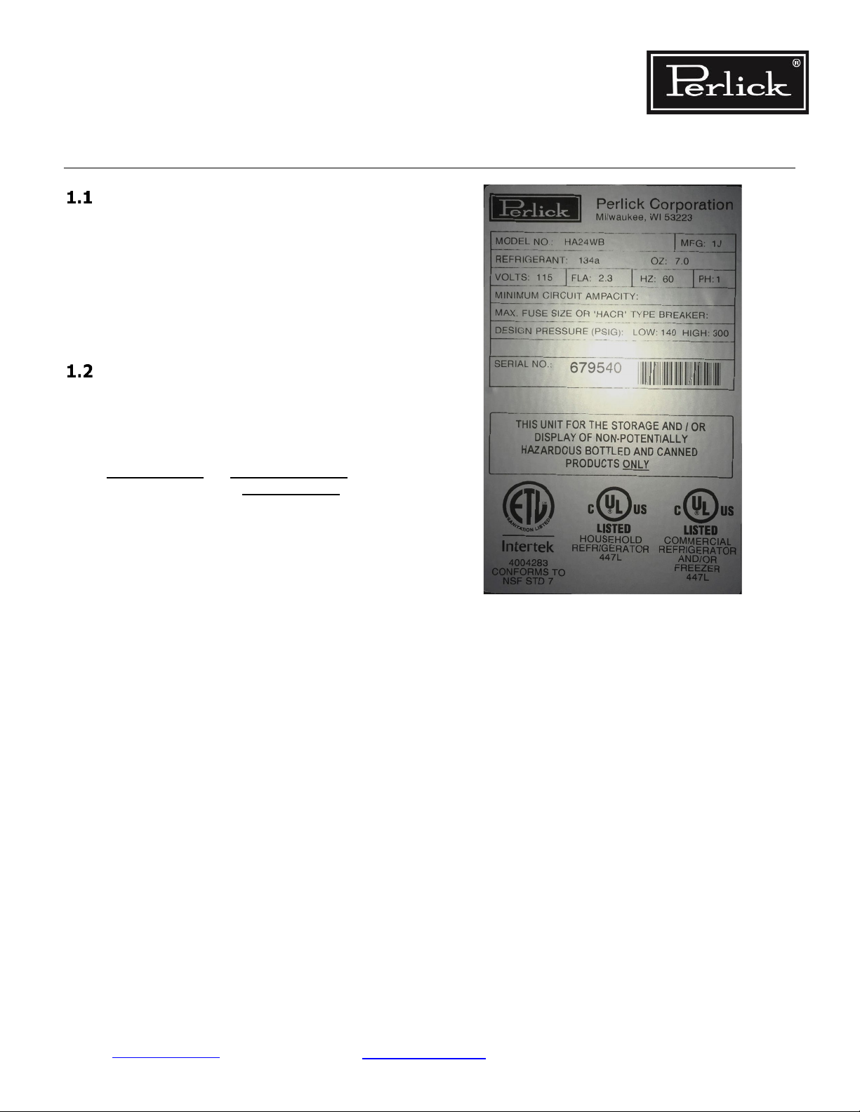
Figure 1-1. Information Plate ........................................................................................... 1-1
Figure 7-1. Sealing Compound at Wiring Pass-through – Back ............................................ 7-1
Figure 7-2. Sealing Compound at Wiring Pass-through – Inside .......................................... 7-2
Figure 7-3. Evaporator Condensate Drain .......................................................................... 7-2
Figure 7-4. Process Tubes ................................................................................................ 7-4
Figure 7-5. Remove Shelves ............................................................................................. 7-4
Figure 7-6. Remove Shelf Slide ......................................................................................... 7-4
Figure 7-7. Remove Pilaster ............................................................................................. 7-4
Figure 7-8. Evaporator Fan Panel Screw Locations ............................................................. 7-5
Figure 7-9. Remove Evaporator Fan Panel ......................................................................... 7-5
Figure 7-10. Deicing Evaporator ....................................................................................... 7-5
Figure 7-11. Check for Obstructions ................................................................................. 7-7
Figure 7-12. Remove Front Grille ...................................................................................... 7-7
Figure 7-13. Clean Condenser Coils .................................................................................. 7-7
Figure 7-14. Condenser Fan Mounting Hardware ............................................................... 7-9
Figure 7-15. Dual Zone F-R Gen 3 Refrigeration System Diagram ....................................... 7-15
Figure 7-16. Dual Zone Med Temp Gen 3 Refrigeration System Diagram ............................. 7-16
Figure 7-17. Freezer Refrigeration System Diagram............................................................ 7-17
Figure 7-18. Med Temp Refrigeration System Diagram ...................................................... 7-18
Figure 8-1. HC24RS & HC24WS Wiring Diagram ................................................................ 8-2
Figure 8-2. HC24FS Wiring Diagram ................................................................................. 8-3
Figure 8-3. HP48 Signature Series Wiring Diagram ............................................................ 8-4
Figure 8-4. HP24 Signature Series Wiring Diagram ............................................................ 8-5
Figure 8-5. HP Freezers Wiring Diagram ........................................................................... 8-6
Figure 8-6. HA Freezers Wiring Diagram ........................................................................... 8-7
Figure 8-7. HP15 Signature Series Wiring Diagram ............................................................ 8-8
Figure 8-8. HC & HH Wiring Diagram ................................................................................ 8-9
Figure 8-9. HA Wiring Diagram ........................................................................................ 8-10
Figure 8-10. HB24BS, HB24RS & HB24WS Wiring Diagram ................................................. 8-11
Figure 8-11. HB24FB & HB24FS ADA Series Wiring Diagram ............................................... 8-12
Figure 8-12. HPA & HHA Wiring Diagram .......................................................................... 8-13
Figure 8-13. HC Wiring Diagram ....................................................................................... 8-14
Figure 8-14. HC48RS, HC48WS, HC48RW & HC48WW Wiring Diagram ................................ 8-15
Figure 8-15. HP24ZS/ZO Wiring Diagram .......................................................................... 8-16
Figure 8-16. HP24CS/CO/DS/DO Wiring Diagram ............................................................... 8-17
Figure 8-17. Temperature Probe ....................................................................................... 8-31
Figure 8-18. Interior LED Light ......................................................................................... 8-32
Figure 9-1. Door Removal ................................................................................................ 9-1
Figure 9-2. Hinge Removal ............................................................................................... 9-2
Table of Figures Page 4
Page 6

Residential Refrigeration
and Front Venting Commercial Refrigeration Service Manual
Figure 9-3. Hinge Installation ........................................................................................... 9-2
Figure 9-4. Door Brackets ................................................................................................ 9-2
Figure 9-5. Removing Front Panel ..................................................................................... 9-3
Figure 9-6. Bearing and V-Block ....................................................................................... 9-3
Figure 9-7. Door Hinges ................................................................................................... 9-3
Figure 9-8. Installing V-Block ........................................................................................... 9-4
Figure 9-9. Installing Door ............................................................................................... 9-4
Figure 9-10. Shelf Locking Mechanism .............................................................................. 9-4
Figure 9-11. Removing/Installing Shelf ............................................................................. 9-5
Table of Contents Page 5
Page 7

Residential Refrigeration
and Front Venting Commercial Refrigeration Service Manual
Table of Tables
Table 7-1. System Operating Pressures ............................................................................. 7-1
Table 7-2. Compressor Data............................................................................................. 7-2
Table 7-3. C0
Table 8-1. Electrical Specications .................................................................................... 8-1
Table 8-2. HA24BB, RB, WB Load Operation Modes .......................................................... 8-18
Table 8-3. HA24FB Load Operation Modes........................................................................ 8-18
Table 8-4. HB24BS, RS, WS Load Operation Modes ........................................................... 8-18
Table 8-5. HB24FS Load Operation Modes ........................................................................ 8-19
Table 8-6. HC24BB, RB, RO, TB, TO WB Load Operation Modes ......................................... 8-19
Table 8-7. HC24FS Load Operation Modes ........................................................................ 8-19
Table 8-8. HC24RS, WS Load Operation Modes ................................................................ 8-20
Table 8-9. HD24RS, WS Load Operation Modes ................................................................ 8-20
Table 8-10. HH24BO, BS, RO, RS, WO, WS Load Operation Modes ..................................... 8-20
Table 8-11. HP15BO, BS, RO, RS, TO, TS, HK15BO, RO, TO Load Operation Modes ............. 8-21
Table 8-12. HP15WO, WS, HK15WO Load Operation Modes .............................................. 8-21
Table 8-13. HP24BO, BS, RO, RS, TO, TS, HK24BO, RO, TO, HM24RO, TO Load Operation
Modes ........................................................................................................................... 8-22
Table 8-14. HP24WO, WS, HK24WO Load Operation Modes .............................................. 8-22
Table 8-15. HP24FO, FS, HK24FO Load Operation Modes .................................................. 8-22
Table 8-16. HP24CO, CS, DO, DS, HK24CO, DO, HM24CO Load Operation Modes ................ 8-23
Table 8-17. HP24ZO, ZS, HK24ZO, HM24ZO Load Operation Modes ................................... 8-24
Table 8-18. HC48RS, RW, WS, WW Load Operation Modes ................................................ 8-25
Table 8-19. HP48WO-S, WW-S Load Operation Modes ...................................................... 8-25
Table 8-20. Factory Temperature Settings ........................................................................ 8-27
Table 8-21. Temperature Resistance Values ...................................................................... 8-32
Table 9-1. Door Hinges .................................................................................................... 9-1
2 equilibrium pressure given volumes of C02 and temperature ......................... 7-1
Table of Tables Page 6
Page 8
Residential Refrigeration
and Front Venting Commercial Refrigeration
Service Manual
1.0 General Information
Use of Service Manual
This service manual is intended for use by a quali-
ed service technician. It is provided as a guide to
diagnose and repair service issues for the product
models listed on the cover.
If you have any questions or require additional
assistance, contact Perlick Customer Service during
regular hours of operation.
Model Families
This manual contains specic instructions for
servicing the Perlick Residential and Front Venting
Commercial Series refrigeration products, which
include the following families:
RESIDENTIAL FRONT VENTING
COMMERCIAL
HA
HC
HH
HC
HB
HD
HK
HM
HP
HHA
HPA
The model and serial numbers can be found on the
Ceiling of the refrigerated space. See Figure 1-1.
Figure 1-1. Information Plate
Return to Table of Contents
General Information Page 1-1
Page 9
Residential Refrigeration
and Front Venting Commercial Refrigeration
Service Manual
2.0 Safety Information
Refrigerant HFC-134a
All self-contained models covered in this service
manual are manufactured using refrigerant HFC134a.
Potential Problems with HFC-134a
HFC-134a compressors are manufactured with a
synthetic based ester oil charge.
• The hygroscopic (water attraction) property of
ester oil is many times greater than that of the
mineral oils previously used with CFC-12.
• High system moisture causes the formation
of acids and alcohol, which can damage the
compressor.
• Systems or components of the refrigeration
system should not be left open to atmosphere
for more than (15) minutes at any time as
humidity from the air will enter the system and
be absorbed by the oil.
To ensure system dehydration:
• System should be evacuated to a level less than
250 microns
• Flux must not be used on any brazed joints.
Anytime a Perlick Refrigeration System is being
serviced:
• It is recommended that the drier be changed
using the exact same style and size within the
system to avoid possible charge problems or
contaminant issues.
Service Manual Safety Labels
PLEASE READ all instructions completely before attempting to service the unit. Take particular note of
the DANGER, WARNING and CAUTION information
in this manual. The information is important for the
safe and efcient service, operation and care of the
Perlick unit.
HAZARD!!
Indicates hazardous situation that will result
in death or serious injury if not avoided.
• When isolated, shall not exceed 500 microns for
a minimum of 10 minutes.
• Vacuum pump oil must never be allowed to
enter the refrigeration system.
• No leak detection dyes are authorized for use
within any Perlick Refrigeration Products.
• Use of these materials will void complete sys
tem warranty and place the burden on the
service company for down-line service issues.
Cleanliness of the system is extremely important.
• The presence of residue (Chlorinated or greasy
residues, mineral oil, or impurities) can lead
to capillary tube restrictions, oil return prob
lems and compressor damage.
• A nitrogen purge should be utilized when
brazing.
Indicates hazardous situation that may
result in death or serious injury if not
avoided.
-
Caution indicates hazardous situation that
could result in minor or moderate injury and
property damage.
Caution without symbol indicates unsafe practice
situation that could result in property damage only.
Return to Table of Contents
Safety Information Page 2-1
Page 10
Residential Refrigeration
and Front Venting Commercial Refrigeration
Service Manual
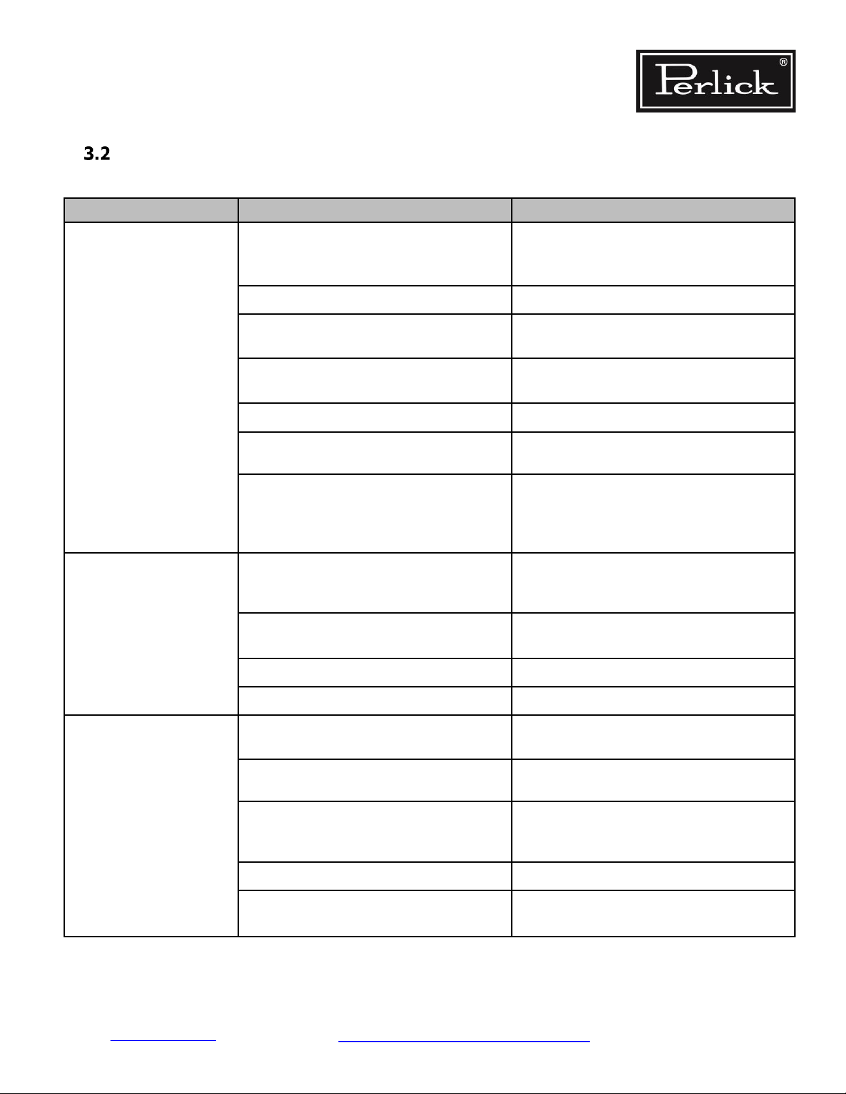
3.0 Trouble Shooting Guide
Refrigeration System
Use this diagnostic guide to identify issues and to locate applicable instructions within this service manual.
This diagnostic guide can be used for any of Perlick’s Residential and Front Venting Commercial Series Re
frigeration Products.
ELECTROCUTION HAZARD!!
Never attempt to repair or perform maintenance
on the unit until the Main electrical power has
been disconnected.
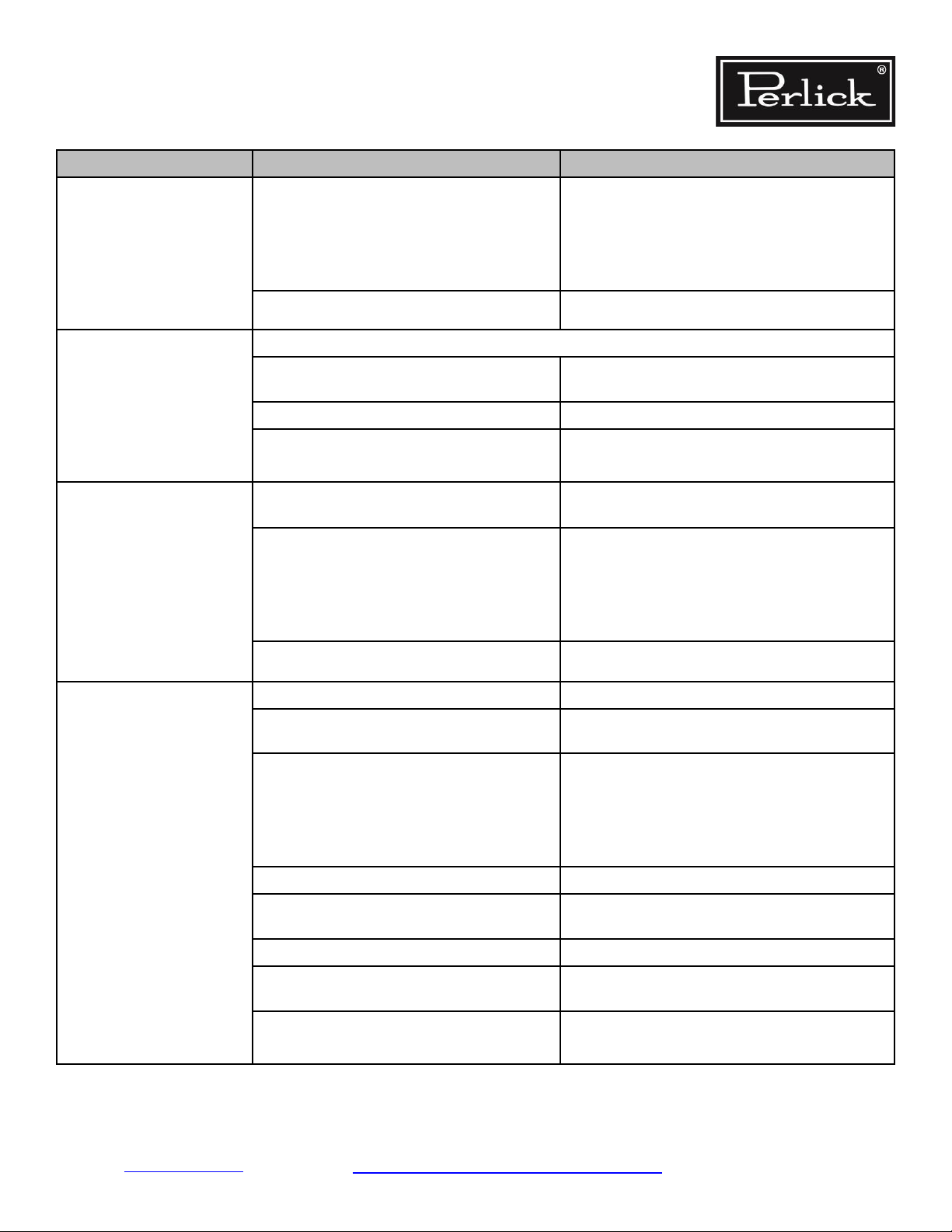
PROBLEM CAUSE SOLUTION
Refrigerator does not run. No power to the unit. Check circuit protection devices. Fuses,
breakers, GFI).
Restore power to unit.
Refer to information plate. See
and
Table 8-1.
Section 1.2
-
Incorrect control settings or faulty control.
Refrigerator is too warm. Power
No power to unit.
Incorrectly wired internal wiring connec
tions.
Fans
Evaporator fan is not running. Refer to Evaporator fan is not running
Coils
Evaporator coil has iced over.
Condensing coil is not clean. Clean with soft brush and vacuum.
Fins are bent or damaged. Straighten ns.
Control
No power to control. Refer to Control not functioning
Control is not calling for cooling. Refer to Control not functioning
Return to factory settings (see
Check outlet for voltage.
Check power cord connection to machine
compartment harness.
Verify wiring per wiring diagram. See
-
Section 8.2.
Reconnect wires if needed.
Remove ice. See
Section 7.4
Section 8.6).
Return to Table of Contents
Troubleshooting Guide - Refrigeration System Page 3-1
Page 11
Residential Refrigeration
and Front Venting Commercial Refrigeration
Service Manual
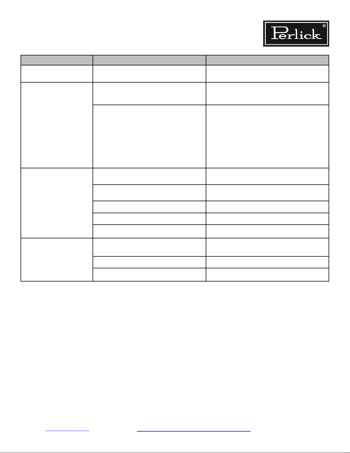
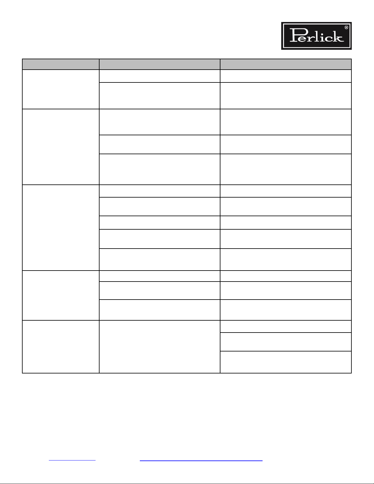
PROBLEM CAUSE SOLUTION
Probe failure.
Refrigerator is too warm.
(continued)
Refrigerator is too cold.
Probe is not connected to the control.
Air Inltration
Sealing compound does not form a com
plete seal.
Door gasket is damaged or out of place.
Condensate drain line/air trap is not
positioned properly.
Incorrect control settings.
Probe failure.
Refer to
place probe if needed. See Section 8.6.4.
Reconnect probe. See
-
Refer to
Refer to
Reposition in loop. See
Return to factory settings.
See
Table 8-21 for resistance values. Re-
Section 8.6.4.
Section 7.1.
Sections 7.1 and 9.5.
Figure 7-3.
Section 8.6.
Table 8-21 for resistance values. Replace
probe if needed. See Section 8.6.4.
Control failure. Refer to Electrical System
Refrigerator runs continu
ously.
-
Condensing coil is dirty. Clean with soft brush and vacuum.
Incorrect control settings.
Probe failure.
Return to factory settings.
Section 8.6.
See
Table 8-21 for resistance values. Replace
Evaporator coil has iced over.
Sealing compound does not form a com
plete seal.
Door gasket is damaged or out of place.
Condensate drain line/air trap is not posi
tioned properly.
Extreme ambient conditions.
probe if needed. See
Remove ice per
-
Refer to
Refer to
-
Reposition in loop. See
Refer to
Section 7.1.
Section 7.1 and 9.5.
Section 7.8.
Section 8.6.4.
Section 7.4.
Figure 7-3.
Return to Table of Contents
Troubleshooting Guide - Refrigeration System Page 3-2
Page 12
Residential Refrigeration
and Front Venting Commercial Refrigeration
Service Manual
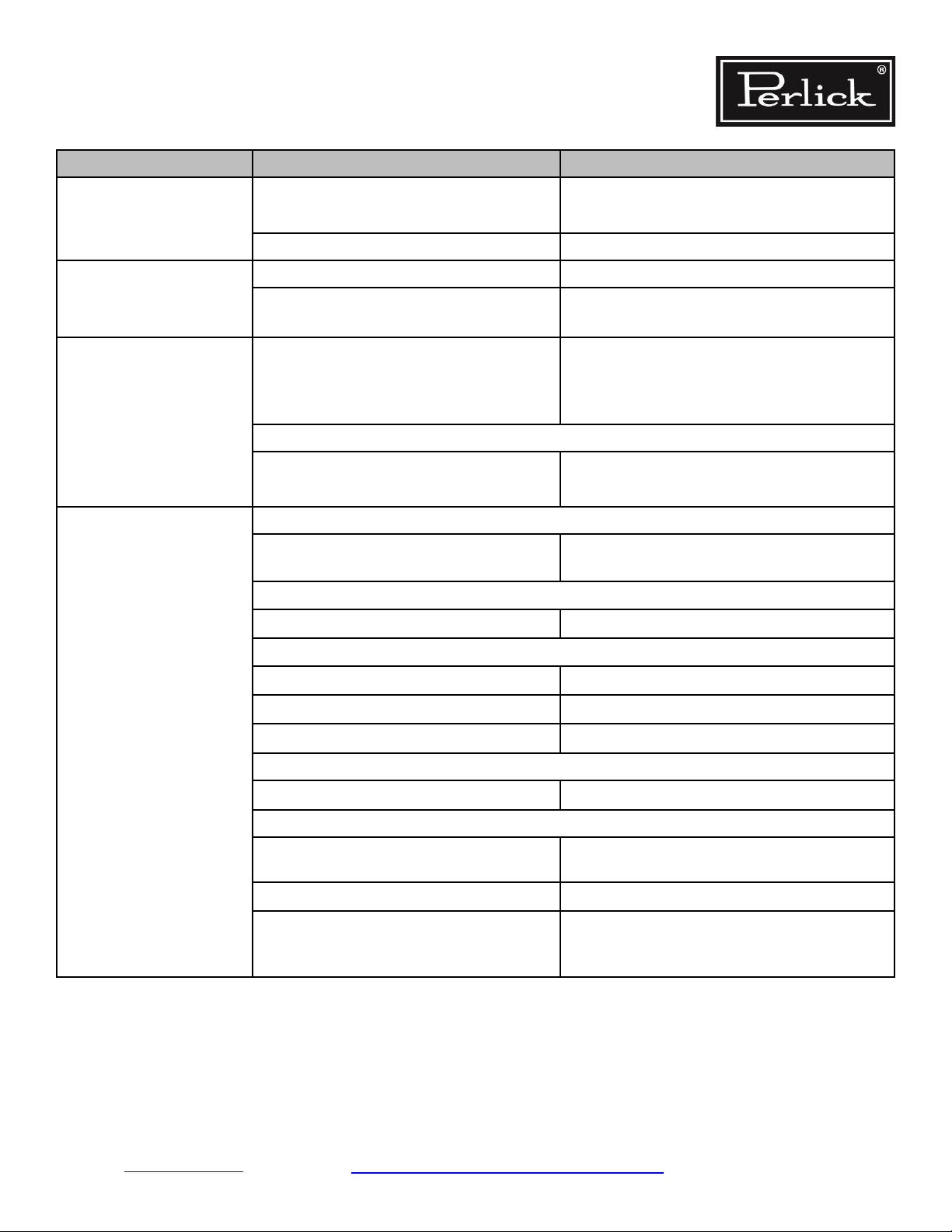
PROBLEM CAUSE SOLUTION
Water on the oor outside
of unit.
Water on the oor outside
of unit.
(continued)
Refrigeration/Charge level is too low.
High ambient temperature and high am
bient humidity conditions coupled with
frequent door opening.
Condensate pan overowing.
Unit is not level.
Sealing compound does not form a com
plete seal.
Door gasket is damaged.
Evaporator coil has iced over.
Evaporator pan and/or drain line restricted. Remove restriction.
Check for leaks, repair, and recharge per
Section 7.13 and 7.14.
Ensure doors close completely.
-
Remove excess water.
Check for the following:
• Air inltration. See
• Doors close completely and seals are
intact. See
• Ice buildup. See
Unit must be level front-to-back and side-toside for water to drain properly.
-
Refer to
Refer to
Remove ice. Refer to
Section 9.0.
Section 7.1.
Sections 7.1 and 9.5.
Section 7.1.
Section 7.4.
Section 7.4
Water on the oor inside
of unit.
Unit is not level.
Evaporator coil has iced over.
Unit must be level front-to-back and side-toside for water to drain properly.
Remove ice. Refer to
Section 7.4
Return to Table of Contents
Troubleshooting Guide - Refrigeration System Page 3-3
Page 13
Residential Refrigeration
and Front Venting Commercial Refrigeration
Service Manual
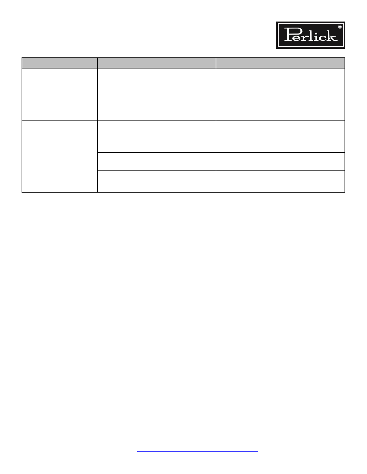
Electrical System
PROBLEM CAUSE SOLUTION
Compressor is not running.
Condenser fan is not running.
No power to compressor.
No call for cooling from control.
Incorrectly wired connections in machine
compartment.
Incorrect control settings.
Faulty control.
Starting device is not operational (start
relay/capacitor).
Faulty compressor.
No power to fan
Incorrectly wired.
Check wiring to compressor.
Check where power is interrupted between
controller and compressor.
Check control settings or for bad control.
Verify wiring per wiring diagram,
Section 8.2.
Return to factory settings.
Section 8.6.
See
Refer to Control not functioning.
Replace compressor electrical components.
Check compressor, see
Restore power to unit.
Refer to information plate. See
Section 7.9
Section 1.0 and Table 8-1
Verify wiring per wiring diagram,
Section 8.2.
Remove obstructions.
Replace condenser fan per
Check wiring and continuity of switch con
tacts. Replace switch if defective.
Install bracket and/or align.
Restore power to unit.
Refer to information plate. See
Section 7.0.
Evaporator fan is not run
ning.
Fan is obstructed.
Fan still does not run.
-
Faulty/defective door switch or wiring to
door switch.
Missing or misaligned door switch plunger
bracket.
No power to evaporator fan motor.
Section 1.0 and Table 8-1
Fan is obstructed.
Incorrectly wired.
Remove obstruction.
Verify wiring per wiring diagram,
Section 8.2.
Return to Table of Contents
Troubleshooting Guide - Electrical System Page 3-4
-
Page 14
Residential Refrigeration
and Front Venting Commercial Refrigeration
Service Manual
PROBLEM CAUSE SOLUTION
Control not functioning
Lights not functioning
If Evaporator fan is still not running
No power to/from DC inverter/driver
(12V).
No power to unit.
Incorrectly wired harness.
No call for cooling.
Light switch in off position.
No power to light.
Faulty LED strip
Faulty/defective door switch or wiring to
door switch.
Replace evaporator fan per
If no power: restore power, replace. Refer to
Section 7.11.
Section 1.1.
Restore power to unit.
Refer to information plate. See
and
Table 8-1
Verify wiring per wiring diagram,
Reconnect wires if needed.
Check probe connections and verify resistance
readings.
Check control settings.
Replace control.
Turn on light switch.
Verify wiring per wiring diagram,
Replace LED strip.
Check wiring for continuity of switch contacts.
Replace switch if faulty.
Section 1.0
Section 8.2.
Section 8.2.
Light stays on when door is
closed.
Eliwell Control: LED
Controller display is ash
ing “E1”
-
Door switch plunger bracket missing or
misaligned.
Manual switch is on. Turn off manual switch.
Faulty/defective door switch or wiring to
door switch.
Door switch plunger bracket missing or
misaligned.
Probe 1 error. Reading out-of-range of
operating values.
Install bracket and/or align properly.
Check wiring and continuity of switch contacts.
Replace switch if faulty.
Install bracket and/or align properly.
Check probe connections to control.
Check probe resistance readings per
Table 8-21.
Check probe wiring.
Return to Table of Contents
Troubleshooting Guide – Beverage Dispensing Page 3-5
Page 15

Residential Refrigeration
and Front Venting Commercial Refrigeration
Service Manual
PROBLEM CAUSE SOLUTION
Eliwell Control: LED
Controller display is ash
ing “AH1”
Eliwell Control: LED
Controller display is ash
ing “AH1”
(continued)
-
-
Probe 1 HIGH temperature alarm.
Control
Incorrect control settings.
Power
Incorrectly wired.
Fans
Evaporator fan is not running.
Coils
Evaporator coil has iced over.
Coils
(continued)
Condensing coil is not clean.
Fins are bent or damaged.
Replace probe per Section 8.6.3.
Return to factory settings. See
Verify wiring per wiring diagram,
Section 8.2.
Refer to Evaporator fan is not running.
Remove ice. See
Clean with soft brush and vacuum.
Straighten ns.
Section 7.4
Section 8.6.
Eliwell Control: LED
Controller display is ash
ing “AL1”
Probe
Probe is not connected to control.
Air Inltration
Sealing compound does not form a
complete seal.
Door gasket is damaged or not seated
properly.
Condensate drain line/air trap is not
positioned properly.
Refrigeration/Charge level is too low.
Probe 1 LOW temperature alarm.
Incorrect control settings.
Reconnect probe.
See Section 8.6.4.
Refer to
Refer to
Reposition in loop.
Check for leaks, repair, and recharge.
See
This is a critically charged system, re
charging should only be done when all
other options have been thoroughly
checked.
Section 7.1.
Section 7.1 and 9.5.
Section 7.13 and 7.14.
Return to factory settings.
See
Sections 8.6.
-
Return to Table of Contents
Troubleshooting Guide – Beverage Dispensing Page 3-6
Page 16
Residential Refrigeration
and Front Venting Commercial Refrigeration
Service Manual
PROBLEM CAUSE SOLUTION
Dixell Control: LED
Controller display is ash
ing “P1”.
Dixell Control: LED
Controller display is ash
ing “HA”. Maximum temperature alarm.
Dixell Control: LED
Controller display is ash
ing “HA”. Maximum temperature alarm.
(continued)
Probe failure.
Control failure. Refer to Control not functioning
Probe failure.
Probe disconnected from control. Plug in probe connector.
Internal compartment has exceeded the
high temperature alarm preset value for
over 30 minutes.
Control
Incorrect control settings.
Power
-
Incorrectly wired.
Fans
Evaporator fan is not running.
Coils
Table 8-21 for resistance values.
Refer to
Table 8-21 for resistance values
Return to factory settings.
See
Section 8.6.
Verify wiring per wiring diagram,
Section 8.2.
Refer to Evaporator fan is not running
Evaporator coil has iced over.
Condensing coil is not clean.
Fins are bent or damaged.
Probe
Probe is not connected to the control.
Air Inltration
Sealing compound does not form a com
plete seal.
Door gasket is damaged or out of place.
Condensate drain line/air trap is not
positioned properly.
Remove ice per
Clean with soft brush and vacuum.
Straighten ns.
Reconnect probe per
-
Refer to
Refer to
Reposition in loop. See
Section 7.1.
Section 7.1 and 9.5.
Section 7.4.
Section 8.6.4.
Figure 7-3.
Return to Table of Contents
Troubleshooting Guide – Beverage Dispensing Page 3-7
Page 17
Residential Refrigeration
and Front Venting Commercial Refrigeration
Service Manual
PROBLEM CAUSE SOLUTION
Check for leaks, repair, and recharge per
Refrigeration/Charge level is too low.
Section 7.13 and 7.14.
Dixell Control: LED
Controller display is ash
ing “LA”. Minimum temperature alarm.
Internal compartment has exceeded the
low temperature alarm preset value for over
30 minutes.
Incorrect control settings.
Probe failure.
This is a critically charged system,
recharging should only be done when
all other options have been thoroughly
checked.
Return to factory settings.
See
Section 8.6.
Table 8-21 for resistance values.
Return to Table of Contents
Troubleshooting Guide – Beverage Dispensing Page 3-8
Page 18
Residential Refrigeration
and Front Venting Commercial Refrigeration
Service Manual
Doors, Drawers and Shelving
PROBLEM CAUSE SOLUTION
Key won’t come out after
door is locked.
Hinge problems, door
misaligned.
Door handles loose
Condensation on glass
doors.
Key not in proper position.
Improper door mounting
Excessive wear
Improper handle mounting
Excessive wear
High ambient temperature, high humidity
and environmental conditions.
Frequent door opening.
Cabinet temperature too low.
Rotate key to the proper position and remove.
Verify proper mounting. Refer to
Section 9.2.
Replace worn parts.
Refer to
Verify proper mounting. Refer to
Replace worn parts. Refer to
Refer to
Condensation may build up on interior of glass
from frequent door openings as the cabinet
comes back down in temperature condensation
will evaporate.
Adjust temperature. Refer to
Factory Temperature Settings.
Section 9.2.
Section 9.7.
Section 9.7.
Section 7.8.
Table 8-20.
Return to Table of Contents
Table of Contents Troubleshooting Guide - Doors, Draws and Shelving Page 3-9
Page 19
Residential Refrigeration
and Front Venting Commercial Refrigeration
Service Manual
Beverage Dispensing
DIRECT DRAW SYSTEMS
PROBLEM CAUSE SOLUTION
Beer Foaming
Temperature too warm
(should be 36° F)
Temperature too cold/frozen beer in lines
(should be 36° F)
Adjust temperature control or call qualied
service person
Adjust temperature control or call qualied
service person
Kinked beer line Change beer line
Wrong diameter or length beer line (should be
Change beer line
6.5 ft. of 3/16” vinyl tubing or possibly even
longer)
2 regulator to brewer’s specication
Applied pressure too high
(should be 12 to 14 psi for most beers)
Adjust C0
(If CO2 pressure has been too high, kegged
product may be over-carbonated and be bad
and not correctable).
Applied pressure too low
(should be 12 to 14 psi for most beers)
Adjust C0
2 regulator to brewer’s specication
Coupler washers bad Replace coupler washers
Faucet washer bad Replace faucet washers
System dirty Clean system or call customer’s line cleaning
service
2 leaks or out of C02 Check ttings, clamps, shut-offs and regulators,
C0
replace as necessary
Beer foaming in jumper - keg valve seal torn or
ripped
If seal is ripped/torn, gas enters the liquid ow
stream causing foaming. Replace keg and report
defective keg to distributor
Beer foaming in jumper - physical obstructions at
coupler-valve junction
Remove any physical obstructions or debris
(e.g. a piece of a dust cover) that could allow
gas to enter the liquid ow
Beer foaming at faucet - clogged vent hole(s)
(If applicable to the faucet being used)
No Beer at Faucet Empty C0
2 bottle Replace with full C02 bottle
Disassemble and clean faucet, or call line
cleaning service
Regulator shutoff closed Open shutoff
2 bottle main valve turned off Tum on C02 bottle main valve
C0
Keg empty Replace with full keg
Coupler not engaged Tap keg properly and engage coupler
Check ball in coupler stuck (If applicable) Free check ball
Line/faucet dirty Clean line/faucet
Return to Table of Contents
Troubleshooting Guide – Beverage Dispensing Page 3-10
Page 20

Residential Refrigeration
and Front Venting Commercial Refrigeration
Service Manual
4.0 Variable Speed Compressor Specication
Never connect compressor directly to AC power!
Always use specied inverter when testing
compressor!
• The compressors employed within many of Perlick’s cabinets are on the cutting edge of technology for
reciprocating hermetic compressors. The compressors are variable speed models developed and man
ufactured by Embraco. Depending on the model of the cabinet, either a VEMY3H, VEMY6H or VEGY7H
will be found powering the refrigeration system. The compressor itself looks like a standard fractional
horsepower hermetic reciprocating compressor. The electrical, overload, relay and capacitor, which
are normally found connected to the compressor pins has been replaced by an electronic box which is
called the inverter.
-
• The inverter is an electronic board, which controls the compressor and has to have power to it at all
times for it to function properly. It controls the starting of the compressor and the speed at which it is
running at from 1600 rpm to 4500 rpm. A normal hermetic reciprocating compressor runs at a con
stant 3600 rpm. The Digital Temperature Control controls a separate power circuit used as the power
to the inverter driver circuit, which turns the compressor on and off.
• The inverter is powered by 115-127V 50-60Hz 1 Ph AC. The inverter driver circuit power is also 115-
127V 50-60Hz 1Ph AC power. The inverter converts this to 230V 53-150Hz 3 Ph power to drive the
compressor. The resistance between any combination of the three compressor pins for the HP24”
Series is 16.07 ohms, and the HP48 & HP72” series is 6.4 ohms. The inverter has a plastic 3-pin recep
tacle which gets plugged onto the compressor pins (can only be installed one way for proper orientation). The inverter also comes with a ground wire, which gets plugged onto the compressor ground
lug. The inverter is then mounted to the compressor fence by sliding it down and tipping to the vertical
position. A single fastener is then used to mount it to the fence (do not over tighten as it is fastening
into the plastic inverter housing).
-
-
Return to Table of Contents
Refrigeration System Repair Instructions Page 4-1
Page 21

Residential Refrigeration
and Front Venting Commercial Refrigeration Service Manual
5.0 Compressor Inverter Operation
• Upon initial power to the inverter, the electronic board is checked for problems or malfunctioning
components. If a problem is detected, the inverter will not allow power to the compressor and will
wait 8 minutes until it will repeat the process to see if it has been corrected.
• If the inverter power circuit is interrupted or reduced to a level below operation level, the inverter will
not allow continued operation of the power circuit to the compressor.
Compressor Start-Up
• Upon the temperature control calling for cooling, the inverter will wait 1-3 seconds before applying
current to the compressor motor for the rst time. In case of any abnormality in trying to start the
compressor (unequal pressures, locked rotor condition or open winding, etc.), the inverter will wait
6 seconds before establishing a new start-up trial.
• The maximum number of start-up trials is 12. If the compressor does not start after 12 trials, a
start-up error is set, and the system will wait for 8 minutes to repeat the starting procedure.
• During start-up of the compressor, the current is limited in accordance with the type of motor
connected to the inverter. The compressor always starts in its minimum rpm condition (1600 rpm)
to conserve energy and alleviate noise associated with a standard compressor start-up.
• During initial power being applied to the refrigerated cabinet, the compressor will always start in its
minimum rpm condition (1600 rpm) and remain at this speed for 7 minutes. After this time has
passed the program will move the compressor to its maximum rpm level until the initial controller
cut-out temperature has been achieved.
Normal Operation
During running condition, the speed is measured each shaft turn and the result is compared with
the desired speed. If the actual speed is lower than desired, the inverter will increase the power applied
to the motor, which in turn will increase the shaft speed until the equilibrium is achieved. The opposite can
happen likewise, in that if the actual speed is higher than the desired speed, the inverter will decrease the
power applied to the motor, which in turn will decrease the shaft speed until the equilibrium is achieved.
The compressor will generally run at its slowest speed (1600 rpm) during normal cycling conditions with
out added load to the cabinet or door openings. This is done to conserve energy and reduce noise. A typical refrigeration system is designed for high load, high ambient conditions, meaning the compressor is
typically oversized for normal daily operation. It has been shown in residential equipment that a refriger
ator or freezer or combination of the two with standard reciprocating compressor is typically designed for
conditions it sees less than 25% of the time (high load/high ambient). While employing the variable speed
compressor the equipment has been designed for the conditions it sees 75% of the time while still having
the capacity to cover the conditions it sees 25% of the time.
-
-
Return to Table of Contents
Troubleshooting Guide – Beverage Dispensing Page 5-1
Page 22
Residential Refrigeration
and Front Venting Commercial Refrigeration
Service Manual
6.0 Troubleshooting Compressor Inverter
• Ensure the inverter has 120V applied to the two pin connector on the inverter. If no power,
check where power is interrupted.
• If temperature control is calling for cooling, check inverter signal circuit for 120V, typically
the red lead. If no power, check where power is interrupted. If there is power, disconnect
power to the entire unit and wait 5 minutes to ensure internal system pressures are
equalized. Plug in unit and feel top of compressor to see if it is trying to start (see in-
formation from section Compressor Start-Up above). If compressor is trying to start, but
unable to, the system could have a restriction, the inverter may not be applying the correct
power to the compressor pins (check pins to see if getting 120V to each pin).
• Resistance between all pins should be the same. Dependent upon temperature of the com-
pressor, resistance could be different than the resistance specied at the standard temperature.
7.0 Refrigeration System Repair Instructions
Air Inltration
Air inltration can occur in several locations.
Note: Unit may manifest longer than normal run
times caused by the additional loads that
air inltration presents.
Signs of air inltration include:
• Presence of water, moisture or ice
• Condensation on glass or metal surfaces
STEP 1. Door Gaskets
• Check door gaskets for rips, cracks, or oth
er damage.
• The door gasket should be pushed in rmly
and lay at.
• Ensure gasket forms a complete seal
around door.
-
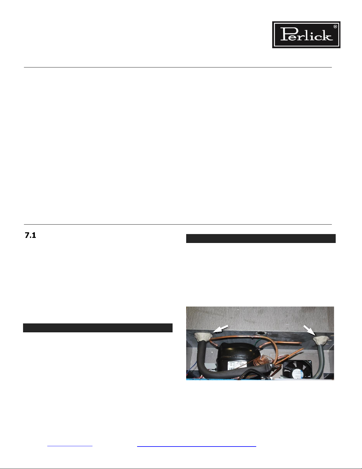
STEP 2. Sealing Compound
• Sealing compound is used to seal wiring and
line set pass-through between the con
denser and the evaporator compartments.
See Figure 7-1 and Figure 7-2.
• Check for voids and ensure sealing
compound completely lls the space.
Figure 7-1. Sealing Compound at Wiring Pass-through –
-
Back
Return to Table of Contents
Troubleshooting Guide – Beverage Dispensing Page 7-1
Page 23
Residential Refrigeration
and Front Venting Commercial Refrigeration
Service Manual
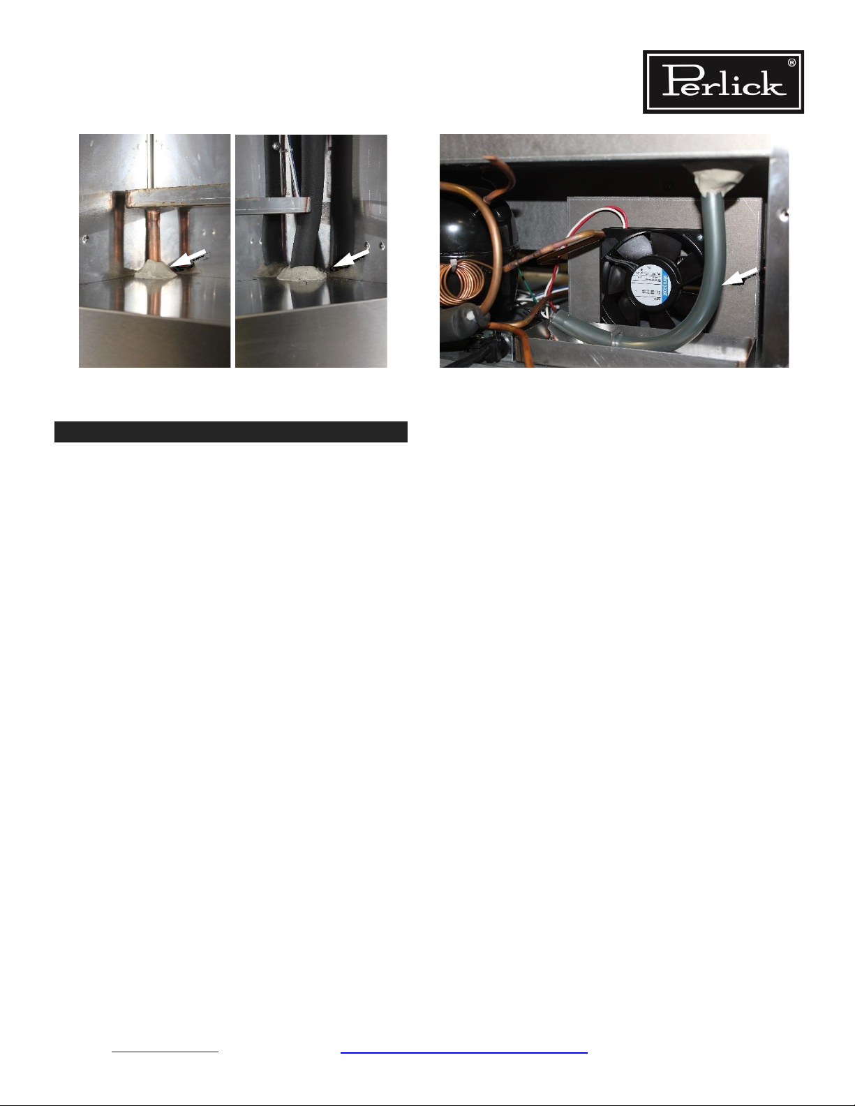
Figure 7-2. Sealing Compound at Wiring Pass-through –
Inside
STEP 3. Drain
Check that the evaporator condensate drain is
secure and connected. Figure 7-3.
Figure 7-3. Evaporator Condensate Drain
Note: Drain tube should be routed through metal
bracket and end of tube should be retained by metal
insert to create a trap. This trap should be lled with
water to prevent air from moving through the tube
and into the cabinet. Sometimes, gurgling sounds
will be heard upon the door closing as the internal
cabinet pressure changes requiring air to be pushed
out which happens through the drain tube trap.
Return to Table of Contents
Refrigeration System Repair Instructions Page 7-2
Page 24
Residential Refrigeration
and Front Venting Commercial Refrigeration Service Manual
System Operating Pressures
Note: To check operating pressures, you must install access valves onto the process tubes. See Section
7.2.1.
Values in
Table 7-1
represent a range of normal pressures. The measured pressure can vary depending on
ambient conditions and at the point at which unit is in the refrigeration cycle.
Operating pressures shown in
Table 7-1 are nominal and dependent on
many factors (box temperature, position in the
refrigeration cycle, cleanliness of the condenser,
etc.), should only be used as reference.
Never add or remove charge based on the
operating pressures in Table 7-1. These prod
ucts are critically charged and must have the
refrigerant charge weighed into the system with
accurate equipment to plus/minus 2 grams.
Table 7-1. System Operating Pressures
70° F
Ambient
90° F 105° F
Models Low/High Low/High Low/High
Freezer 4” Hg/105 PSIG 3” Hg/145 PSIG 2” Hg/185 PSIG
Medium Temp* 15 PSIG /110 PSIG 16 PSIG /150 PSIG 17 PSIG /190 PSIG
Dual Zone Frz/Ref 5” Hg/105 PSIG 4” Hg/145 PSIG 3” Hg/185 PSIG
Dual Zone Medium Temp** 12 PSIG /110 PSIG 13 PSIG /150 PSIG 14 PSIG /190 PSIG
*Medium Temp = Refrigerator, Beverage Center, Wine Reserve, Beer Dispenser
**Dual Zone Medium Temp = Ref/Wine and Wine/Wine
Return to Table of Contents
Refrigeration System Repair Instructions Page 7-3
Page 25
Residential Refrigeration
and Front Venting Commercial Refrigeration
Service Manual
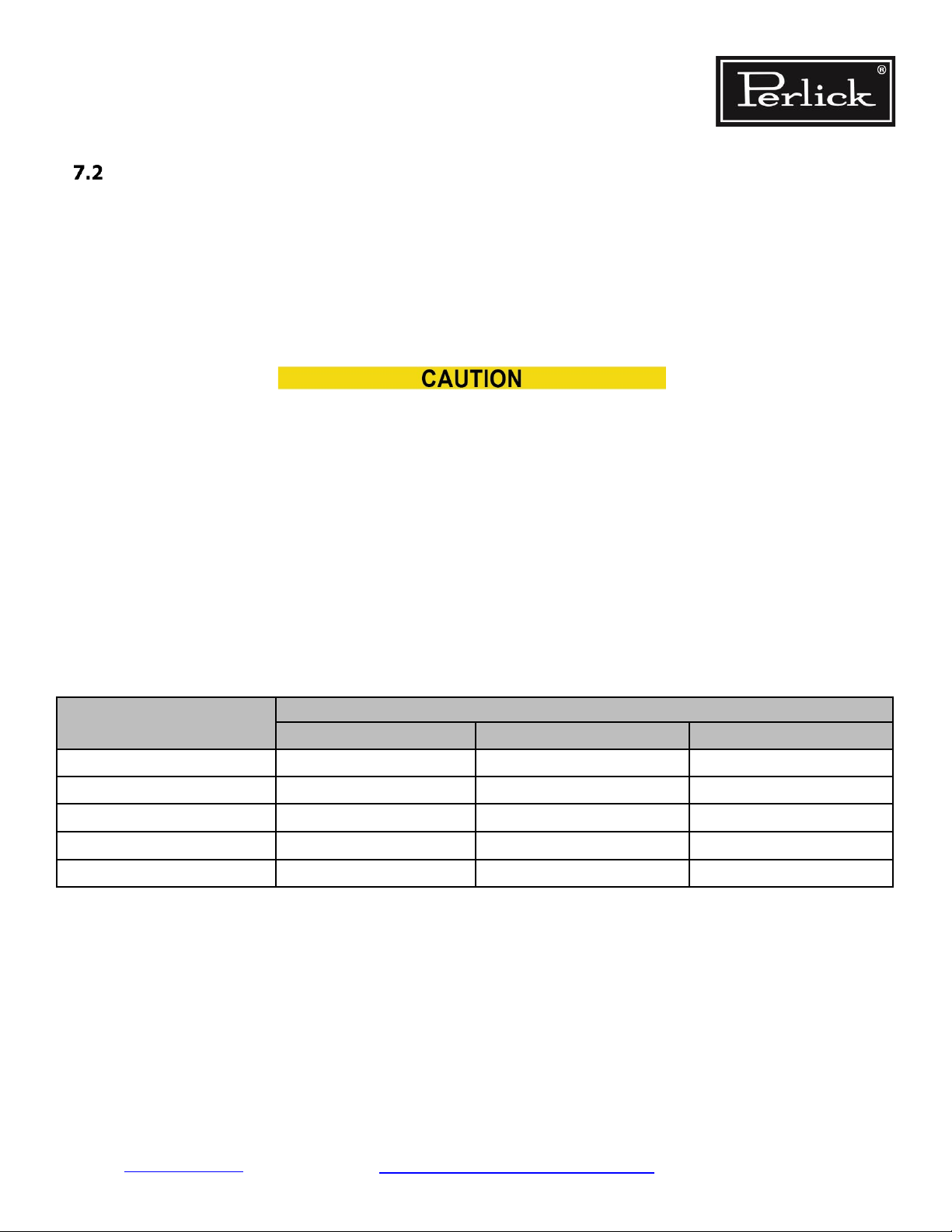
7.2.1 Process Tubes and Access Valve
Refrigerant system is hermetically sealed. Use
access tubes to charge unit and check pressure.
Note: Access valves (saddle valves) are not
provided and may vary.
Access valves should never be left on the
equipment permanently as they tend to
leak over time. Install Schrader valves any
time the system has been accessed.
Shelf
Lock
Figure 7-5. Remove Shelves
Saddle
Valve
Figure 7-4. Process Tubes
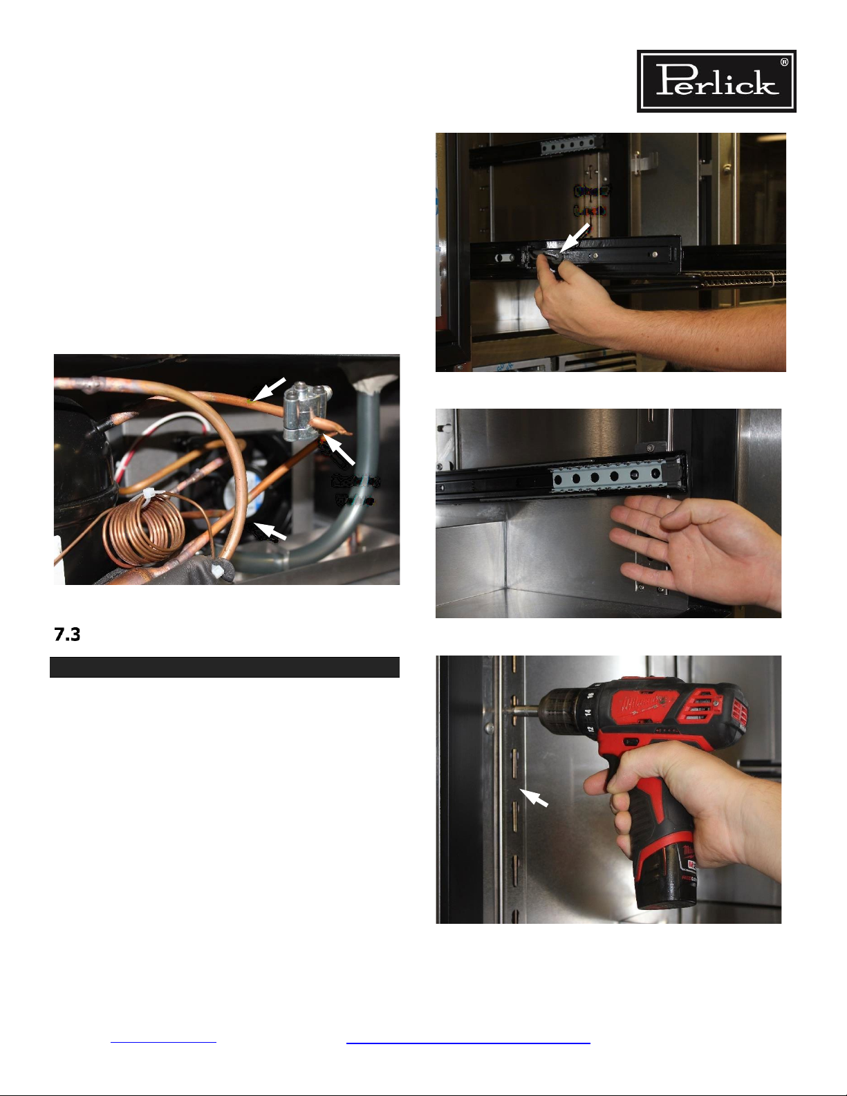
Remove Evaporator Fan Panel STEP
STEP 1.
Remove shelves, shelf slides and pilasters from
refrigerator section nearest the evaporator coil.
To remove a full extension shelf, pull shelf out so it
is fully extended, release lock mechanism on each
slide and pull out shelf. See Figure 7-5.
To remove the slides, lift up on front of slide and
pivot slightly inward to remove from the front
pilaster key slot. Pull slide forward to remove slide
from rear pilaster key slot. See Figure 7-6.
Remove screws from pilasters and remove. See
Figure 7-7.
Figure 7-6. Remove Shelf Slide
Figure 7-7. Remove Pilaster
Return to Table of Contents
Refrigeration System Repair Instructions Page 7-4
Page 26
Residential Refrigeration
and Front Venting Commercial Refrigeration
Service Manual
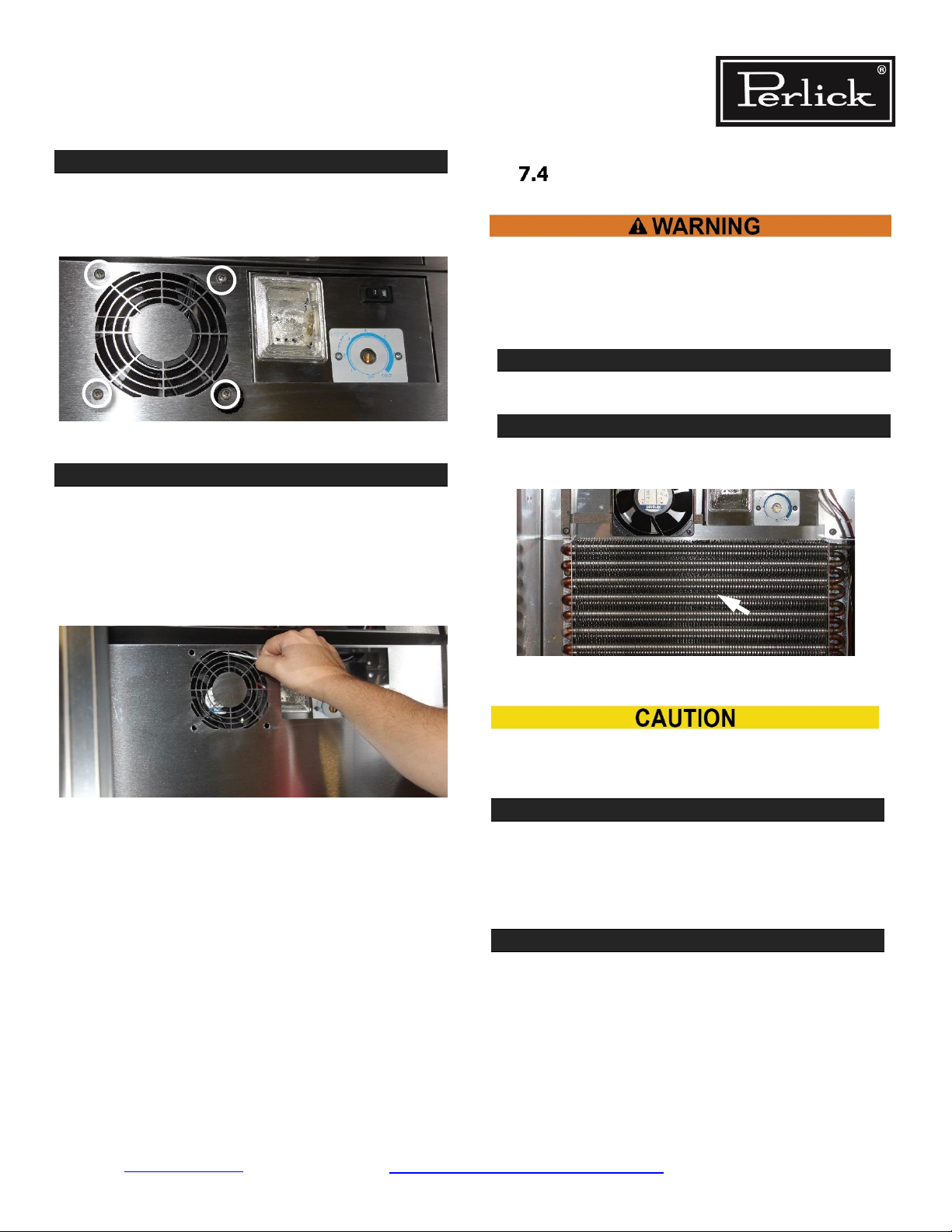
STEP 2.
Remove Evaporator Fan panel by removing 2 (or
4) Phillips head screws from around the evaporator
fan. See Figure 7-8.
Figure 7-8. Evaporator Fan Panel Screw Locations
STEP 3.
Pull outward from fan cutouts using a small
screwdriver, tilt panel top out towards you.
Pull up on panel to release anges from the
bottom inner liner of cabinet.
Carefully remove panel from cabinet.
De-Ice Blocked Evaporator Coil
Use towels to absorb water to avoid damage to ma-
chine compartment or surrounding ooring. Machine
compartment condensate pan may overow if manu-
ally defrosted without use of towels.
STEP 1.
Remove evaporator fan panel. See Section 7.3.
STEP 2.
Using a fan or heat gun to gently direct warm air
over ice to remove. See Figure 7-10.
Figure 7-9. Remove Evaporator Fan Panel
Figure 7-10. Deicing Evaporator
DO NOT use any tools to chip at or physically
remove ice!
STEP 3. When ice has been removed:
Check sealing compound. Re-forming, if necessary,
to close any gaps around wire harness and piping.
Check for other potential sources of air inltration.
See Section 7.1.
STEP 4.
Reverse steps in Section 7.3 to close the
evaporator fan panel.
Return to Table of Contents
Refrigeration System Repair Instructions Page 7-5
Page 27
Residential Refrigeration
and Front Venting Commercial Refrigeration
Service Manual
Evaporator Airow by Model
Standard-In at the bottom through louvers, out at
the top through fan.
Model
Evaporator Airow
Direction
HA24BB Standard
HA24FB Standard
HA24RB Standard
HA24WB Standard
HB24BS Standard
HB24FS Standard
HB24RS Standard
HB24WS Standard
HC24FS Standard
HC24RS Standard
HC24WS Standard
HC48RS Standard
HC48RW Standard
RC48WS Standard
HC48WW Standard
HD24RS Standard
HD24WS Standard
HH24BO Standard
HH24BS Standard
HH24RO Standard
HH24RS Standard
HH24WO Standard
HH24WS Standard
HHA24BO Standard
HHA24RO Standard
HHA24WO Standard
HK24BO Standard
HK24FO Standard
HK24RO Standard
HK24TO Standard
HK24WO Standard
HM24RO Standard
HM24TO Standard
HP24BO Standard
HP24BS Standard
HP24FO Standard
HP24FS Standard
HP24RO Standard
Return to Table of Contents
Return to Table of Contents Refrigeration System Repair Instructions Page 7-6
HP24RS Standard
HP24TO Standard
HP24TS Standard
HP24WO Standard
HP24WS Standard
HPA24BO Standard
HPA24RO Standard
HPA24WO Standard
HP48WO-S Standard
HP48WW-S Standard
Reverse-In at the top through fan, out at the
bottom through louvers
Model Evaporator Airow Direction
HC24BB Reverse
HC24RB Reverse
HC24RO Reverse
HC24TB Reverse
HC24TO Reverse
HC24WB Reverse
HK15BO Reverse
HK15RO Reverse
HK15TO Reverse
HK15WO Reverse
HK24CO Reverse
HK24DO Reverse
HK24ZO Reverse
HM24CO Reverse
HP15BO Reverse
HP15BS Reverse
HP15RO Reverse
HP15RS Reverse
HP15TO Reverse
HP15TS Reverse
HP15WO Reverse
HP15WS Reverse
HP24CO Reverse
HP24CS Reverse
HP24ZO Reverse
HP24ZS Reverse
Page 28
Residential Refrigeration
and Front Venting Commercial Refrigeration
Service Manual
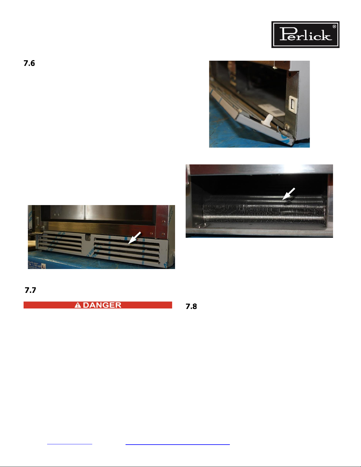
Air Flow Obstructions
The unit must have free air ow to front grille to
operate properly.
Restricted air ow results in high head pressures
and reduction in efciency due to longer run times.
Proper air ow through condenser and evaporator is
necessary for efcient operation.
• Never obstruct air ow in and out of the
machine compartment.
• The front grille must be free from
obstructions, dust, and debris.
• Never obstruct air ow to Evaporator Fan.
• Make sure higher temperature ambient air from
another unit is not directed to condenser coil
(i.e. another heat source directly across from
the unit).
Figure 7-12. Remove Front Grille
Figure 7-11. Check for Obstructions
Clean Condenser Coil
ELECTROCUTION HAZARD!! Never attempt
to repair or perform maintenance on the unit
until the Main electrical power has been dis
connected.
Perlick’s warranty does not cover cleaning of con
denser.
The condenser is located directly behind the front
grille. See Figure 7-11 through Figure 7-13.
-
-
Figure 7-13. Clean Condenser Coils
Condenser coils that are covered with dust and de-
bris restrict air ow. This results in high head pressures and lower efciency due to longer run times.
Use soft brush and vacuum to clean coil every 90
days, or more often if conditions require.
Ambient Temperature
High ambient temperature and high humidity conditions may result in performance issues and/or refrigeration system failure.
The unit must be protected from precipitation.
Do not subject to direct solar load.
Under extreme temperature and/or relative humidity
conditions the front face, gasket and/or glass door
may show signs of condensation. When temperature
and/or relative humidity conditions return to normal
condensation will disappear.
Return to Table of Contents
Refrigeration System Repair Instructions Page 7-7
Page 29

Residential Refrigeration
and Front Venting Commercial Refrigeration
Service Manual
Compressors
Table 7-2. Compressor Data
START
WINDING
COMPRESSOR
MODEL HP
EM30HHR 1/10 RSIR 20.9 5.5 14.5
EM65HHC 1/6+ RSCR 3.7 3.2 15.0 PTC
EM20HSC 1/10 RSCR 13.2 9.3 5.2 TSD2-115V
EM3D50HLT 1/5 RSCR 5.9 5.4 8.0
VEGY3H 1/10 BPM 16.1 16.1 2.1 Inverter Inverter N/A
VEGY7H 1/4 BPM 6.4 6.4 3.3 Inverter Inverter N/A
MOTOR
TYPE
RESISTANCE
Ω AT 77°F
(+/-8%)
RUN
WINDING
RESISTANCE
Ω AT 77°F
(+/-8%)
LOCKED
ROTOR
AMPERAGE
(LRA)
STARTING
DEVICE
Current
Relay
TSD2-
115V0.6
MOTOR
PROTECTION
4TM575MFBYY-
53
4TM427NFBYY-
53
4TM189KFBYY-
53
4TM302KFBYY-
53
CAPACITOR
(Run/Start)
(uF/VAC Minimum)
Run (20/170)
Run (5/175)
Run (15/200 or
N/A
12/200)
Return to Table of Contents
Refrigeration System Repair Instructions Page 7-8
Page 30
Residential Refrigeration
and Front Venting Commercial Refrigeration
Service Manual
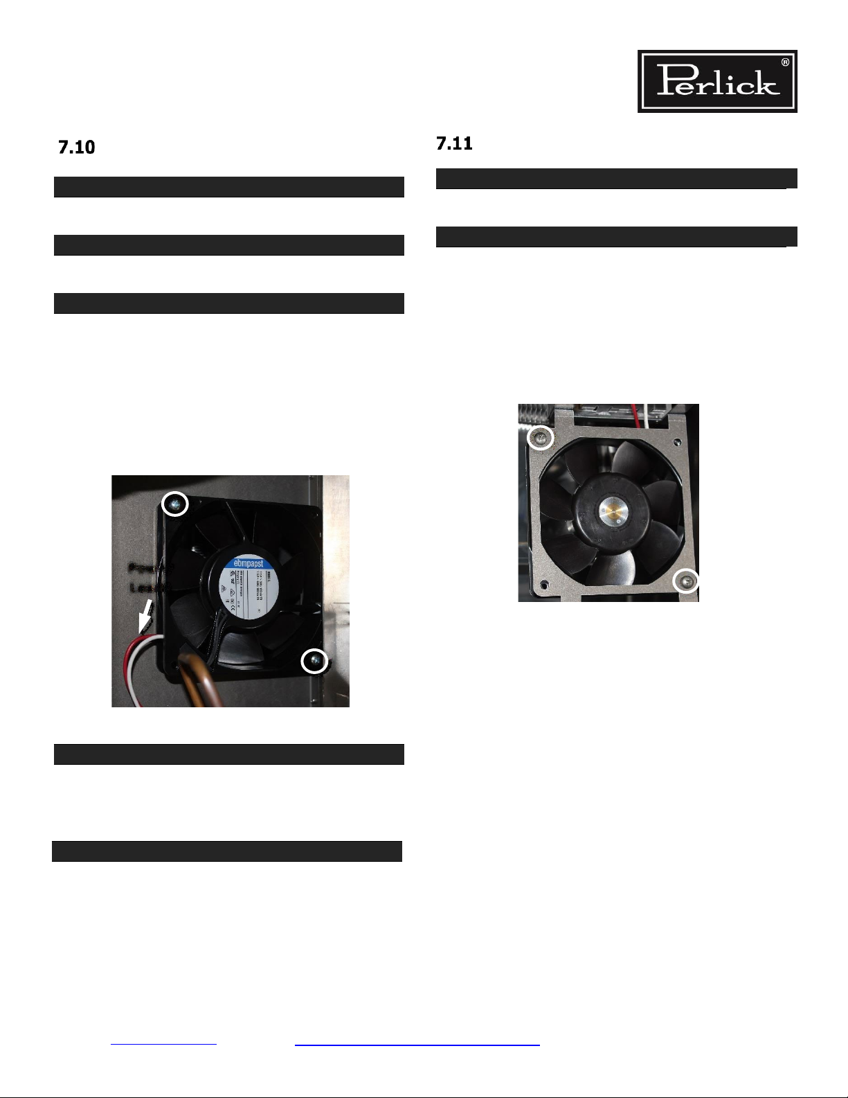
Replace Condenser Fan Motor
STEP 1.
Remove equipment compartment rear cover.
STEP 2.
Unplug the fan power leads. See Figure 7-14.
STEP 3.
Note orientation of fan motor (air should be pulled
through the condenser). Remove fan motor by
removing 2 Phillips head screws that hold the
fan bracket. The condensate pan may need to be
removed to access the screws (condensate pan is
installed using double sided tape). If the conden
sate pan is removed, reinstall properly to prevent
vibration/noise issues.
-
Replace Evaporator Fan Motor
STEP 1.
Remove evaporator fan panel. See Section 7.3.
STEP 2.
Note orientation of the fan motor so when re-in
stalled, the unit has the correct direction of airow.
Remove 2 Phillips head screws that hold fan to
bracket.
NOTE: The evaporator fan bracket may need to
be removed from the rear wall of the cabinet (4
screws) to access the fasteners holding the fan in
place.
-
Power
Leads
Figure 7-14. Condenser Fan Mounting Hardware
STEP 4.
Install new fan motor using 2 Phillips head screws
and connect power leads. Use only original Perlick
OEM parts.
STEP 5.
Install equipment compartment rear cover.
Return to Table of Contents
Refrigeration System Repair Instructions Page 7-9
Page 31

Residential Refrigeration
and Front Venting Commercial Refrigeration
Service Manual
STEP 3.
Disconnect evaporator fan wire leads from main
wiring harness.
STEP 4.
Evaporator fan motor can now be replaced. Evapo
rator fan motor should only be replaced with Perlick
OEM parts.
mining where original refrigerant charge
exited the sealed system!
• Placing a system that has lost refrigerant
under a vacuum without rst repairing the
leak will draw contaminants into the system
through the point of leak. Find source of the
leak and correct it!
• The use of an electronic leak detector is
highly encouraged.
• If the entire charge has leaked out of the unit,
the sealed system should be pressurized with
200 lbs. of dry nitrogen and tracer refriger
ant. Then use an electronic leak detector or
a soap and water solution to pinpoint the
location of the leak. Never use soap and water
solution on a system that is in a vacuum.
• Be certain to check all brazed connections
thoroughly for leaks. Look for spots where
the sealed system components might have
-
been worn through by structural or cabinet
components. Additionally, look for oil that
has leaked from the system to determine the
location of a leak.
-
STEP 5.
Reverse steps in Section 7.3 to close the
evaporator fan panel.
NOTE: Ensure airow is in the correct direc
tion (see section 7.5).
Replace Compressor
-
• Note: Never try and add or remove refrigerant
from the system. These products are critically
charged and must have an ID plate quantity
charge injected to run properly.
Recharge Procedure
STEP 1.
Check that the system been properly installed,
To gain access to compressor, remove the rear
pressure tested, and evacuated.
equipment compartment cover from the back of the
cabinet.
Compressor should only be replaced with Perlick
OEM parts.
Always replace drier when replacing compressor.
STEP 2.
Condenser and evaporator must be clean. Evapo
rator fan and condenser fan blades must be able to
move the correct amount of air.
STEP 3.
Compressor and drier connections should never be
de-soldered as this can cause contamination issues
to move in the system. Always cut tubing using nor
mal refrigeration servicing practices.
Leak Detection
If during a check of operating system pressures, it
is determined that refrigerant level is low, you must
Before installing gauges, vent hoses and manifold
with refrigerant type used in unit. This avoids in
troduction of air into system.
STEP 4.
Use process tubes and Schrader valves. See
Section 7.2.1.
perform a leak test.
STEP 5.
• Do not recharge a system without rst deter
Charge weightl is listed on unit information plate.
See Figure 1-1.
Return to Table of Contents
Refrigeration System Repair Instructions Page 7-10
-
-
Page 32

Residential Refrigeration
and Front Venting Commercial Refrigeration
Service Manual
Once charge level has been set, avoid installing
gauges as part of regular service. System should
be kept sealed.
Do not “top off” or add refrigerant to an unknown
existing charge.
Completely recover existing refrigerant in accor
dance with EPA regulations and thoroughly evacuate the system.
After evacuating the system:
1. Close high side valve and weigh in correct
total charge amount per the I.D. plate.
2. During charging, plug in the unit so the sys
-
tem operates to reduce low side pressure.
3. Upon complete charge being weighed in,
remove charging line set with minimal pres
-
sure remaining in the line set.
4. Note: Never remove line set when in a vac
uum as containments can be sucked into the
system.
Replace compressor starting
device
STEP 1.
Remove equipment compartment rear cover panel
(6 Phillips head screws).
STEP 3.
Use screw driver to pry off overload relay and
starting device.
STEP 4.
Starting device and overload device are now
accessible. Remove leads and replace.
STEP 2.
On side of compressor, lift tab to remove gray
cover.
Starting
device
Return to Table of Contents
Refrigeration System Repair Instructions Page 7-11
Overload
device
Page 33

Residential Refrigeration
and Front Venting Commercial Refrigeration
Service Manual
Beverage Dispensing
Perfectly poured draught beer is the result of
proper temperature, gas pressure, mixture, and
a well-maintained draught beer system. It’s easy
to take all the variables for granted when beer
is pouring well. But improperly pouring beer
can be very frustrating, and can result in loss of
sales- This chapter is intended to provide useful
troubleshooting steps anyone can follow to solve
draught beer dispense problems.
The single most common cause of problems
encountered in draught beer dispense systems
is temperature control. The rst step in solving
any dispensing problem is to conrm that the
temperature of the keg and the cooler are where
they are supposed to be. In air-cooled and
glycol-cooled systems, the next step is to check
the temperature of the beer being delivered to
the faucet, conrming that the air and glycol
systems
used to maintain proper beer line temperature are
working properly.
The troubleshooting steps that follow are
organized by the type of draught beer system and
how the systems are cooled, using air. Direct-draw
systems cooled by air or glycol each have unique
features that are addressed in the troubleshooting
steps
Other steps including gas pressure and supply,
beer supply, and mechanical issues are also
discussed.
Perfect
Carbonation
Under
Carbonation
Over
Carbonation
C02 gauge pressure, temperature and carbonation level reference chart
Table 7-3. C02 equilibrium pressure given volumes of C02 and temperature
Vol. CO2 2.1 2.2 2.3 2.4 2.5 2.6 2.7 2.8 2.9 3.0 3.1
Temp. °F psi psi psi psi psi psi psi psi psi psi psi
33 5.0 6.0 6.9 7.9 8.8 9.8 10.7 11.7 12.6 13.6 14.5
34 5.2 6.2 7.2 8.1 9.1 10.1 11.1 12.0 13.0 14.0 15.0
35 5.6 6.6 7.6 8.6 9.7 10.7 11.7 12.7 13.7 14.8 15.8
36 6.1 7.1 8.2 9.2 10.2 11.3 12.3 13.4 14.4 15.5 16.5
37 6.6 7.6 8.7 9.8 10.8 11.9 12.9 14.0 15.1 16.1 17.2
38 7.0 8.1 9.2 10.3 11.3 12.4 13.5 14.5 15.6 16.7 17.8
39 7.6 8.7 9.8 10.8 11.9 13.0 14.1 15.2 16.3 17.4 18.5
40 8.0 9.1 10.2 11.3 12.4 13.5 14.6 15.7 16.8 17.9 19.0
41 8.3 9.4 10.6 11.7 12.8 13.9 15.1 16.2 17.3 18.4 19.5
42 8.8 9.9 11.0 12.2 13.3 14.4 15.6 16.7 17.8 19.0 20.1
Based on Data from “Methods of Analysis,’ American Society of Brewing Chemists, 5th Edion – 1949
• The values in this table assume sea-level altitude, beer specic gravity of 1015, and beer alcohol
content at 3.8% abw or 4.8% abv. Values shown are in psig or gauge pressure.
• It’s important to remember that carbonation is proportional to absolute pressure, not gauge pres
sure. Atmospheric pressure drops as elevation goes up. Therefore, the gauge pressure needed to
achieve proper carbonation at elevations above sea level must be increased. Add 1 psi for every
2,000 feet above sea level. For example, a retailer at sea level would use 11.3 psi gauge pressure to
-
Return to Table of Contents
Refrigeration System Repair Instructions Page 7-12
Page 34

Residential Refrigeration
and Front Venting Commercial Refrigeration
Service Manual
maintain 2.5 volumes of C02 in beer served at F. That same retailer would need 13.3 psi gauge
pressure at 4,000 feet elevation to maintain 5 volumes of C0
2.
Calculate ideal gauge pressure of
straight C02
Carbonation level not known.
STEP 5.
Set the regulator pressure to 5 psi.
STEP 6.
Tap a fresh keg. Make sure the keg has been in
the cooler long enough to be at the cooler tem
perature.
STEP 7.
Pour a small amount of beer through the faucet.
STEP 8.
Observe the beer in the draught line directly
above the keg coupler (with a ashlight if nec
essary), inspecting for bubbles rising up from the
beer in the keg.
STEP 9.
If bubbles are present, raise the regulator
pressure 1 psi.
-
-
in the system. Below, you’ll nd instructions on
how to properly and thoroughly clean your beer
dispenser.
Tools required
Perlick Cleaning Kit
(Part No. 63797):
check ball lifter
cleaning pump jar
cleaning brush
coupling washer
STEP 10.
spanner wrench
Repeat steps 3 - 5 until no bubbles are present.
STEP 11.
Check the keg temperature 24 hours after setting
4 oz. BLC line cleaning
chemical
the initial gauge pressure to assure temperature
stability, and to reset the gauge pressure as need
-
ed due to a change in keg temperature.
This is the lowest pressure at which the gas in
Buckets
Water
the beer is not escaping. This is your ideal gauge
pressure.
Beer Dispenser Cleaning
To ensure brewery-fresh avor, it is recommended
that the beer system be cleaned after every barrel
or every two weeks to eliminate bacteria, yeast
The chemicals used to clean beer lines are
hazardous. Please follow all recommended
safety instructions on the chemical’s
container.
and beer stone build-up
Return to Table of Contents
Refrigeration System Repair Instructions Page 7-13
Page 35

Residential Refrigeration
and Front Venting Commercial Refrigeration
Service Manual
STEP 1.
Turn off the CO2, either at the CO2 cylinder or at
the air distributor.
STEP 2.
Remove tapping device (keg coupler) from the
barrel.
STEP 3.
If tapping device contains a check ball, insert check
ball lifter into the bottom of the coupler (Perlick
Low Prole Coupler does not contain a check ball).
STEP 4.
Place tapping device into a small bucket.
STEP 5.
Using a spanner wrench, remove the beer faucet
from the dispensing head.
STEP 6.
Fill cleaning pump with warm water.
STEP 7.
Attach cleaning pump jar connector with washer
to where faucet was removed from dispensing
head.
STEP 8.
Pump the warm water through the system to re
move all remaining beer from the system. Empty
tapping device bucket and rinse out. Place tapping
device back into the bucket.
STEP 9.
Fill cleaning pump jar with water and cleaning
chemical per the recommendations on the cleaning
chemical container.
STEP 10.
Pump cleaning solution into system, leaving about
a 1/2 the solution in the cleaning pump jar.
STEP 11.
Let stand 15 minutes, then pump remaining
solution through the system.
STEP 12.
Using a cleaning brush, clean the exterior
surfaces of the tapping device and rinse with
clean fresh water
STEP 13.
Rinse out cleaning pump jar with fresh water
STEP 14.
Fill cleaning pump jar with clean warm water and
pump entire jar through the system
STEP 15.
Repeat STEP 13 using clean cold water
STEP 16.
During the 15 minutes that the solution is in
the system, mix a small container with water
and cleaning chemical per the instructions on the
cleaning chemical container and disassemble the
faucet per faucet manufacturers recommenda
-
tions and let soak in solution
STEP 17.
Using cleaning brush, clean the components of
the faucet
STEP 18.
Rinse all components of the faucet in clean fresh
water. Check all seals on the faucet for wear and
replace if necessary
STEP 19.
Reassemble faucet
STEP 20.
Remove cleaning pump jar from dispensing
tower connection and reinstall faucet using
spanner wrench to tighten properly
STEP 21.
Turn on CO
Return to Table of Contents
Refrigeration System Repair Instructions Page 7-14
2 and tap new keg
Page 36

Residential Refrigeration
and Front Venting Commercial Refrigeration
Service Manual
Refrigeration System Diagrams
Figure 7-15. Dual Zone F-R Gen 3 Refrigeration System Diagram
Dual Zone: Freezer/Refrigerator
ITEM
NUMBER
DESCRIPTION
ITEM
NUMBER
DESCRIPTION
1 Compressor 9 Evaporator Fan (Lower)
2 Condenser 10 Temperature Control
3 Condenser Fan 11 Liquid Line Solenoid (Upper)
4 Drier 12 Capillary Tube (Upper)
5 Hot – Gas Bypass Valve 13 Heat Exchanger (Upper)
6 Capillary Tube (Lower) 14 Evaporator (Upper)
7 Heat Exchanger (Lower) 15 Evaporator Fan (Upper)
8 Evaporator (Lower)
Return to Table of Contents
Refrigeration System Repair Instructions Page 7-15
Page 37

Residential Refrigeration
and Front Venting Commercial Refrigeration
Service Manual
Figure 7-16. Dual Zone Med Temp Gen 3 Refrigeration System Diagram
Dual Zone: Refrigerator/Wine, Wine/Wine
ITEM
NUMBER
DESCRIPTION
ITEM
NUMBER
DESCRIPTION
1 Compressor 9 Evaporator Fan (Lower)
2 Condenser 10 Temperature Control
3 Condenser Fan 11 Liquid Line Solenoid (Upper)
4 Drier 12 Capillary Tube (Upper)
5 N/A 13 Heat Exchanger (Upper)
6 Capillary Tube (Lower) 14 Evaporator (Upper)
7 Heat Exchanger (Lower) 15 Evaporator Fan (Upper)
8 Evaporator (Lower)
Return to Table of Contents
Refrigeration System Repair Instructions Page 7-16
Page 38

Residential Refrigeration
and Front Venting Commercial Refrigeration
Service Manual
Figure 7-17. Freezer/Commercial Chiller Refrigeration System Diagram
Freezer/Commercial Chiller
ITEM
NUMBER
DESCRIPTION
ITEM
NUMBER
DESCRIPTION
1 Compressor 6 Capillary Tube
2 Condenser 7 Heat Exchanger
3 Condenser Fan 8 Evaporator
4 Drier 9 Evaporator Fan
5 Hot - Gas Bypass Valve 10 Temperature Control
Return to Table of Contents
Refrigeration System Repair Instructions Page 7-17
Page 39

Residential Refrigeration
and Front Venting Commercial Refrigeration
Service Manual
Figure 7-18. Med Temp Refrigeration System Diagram
Refrigerator/Beverage Center/Wine Res/Beer Dispenser
ITEM
NUMBER
DESCRIPTION
ITEM
NUMBER
DESCRIPTION
1 Compressor 6 Capillary Tube
2 Condenser 7 Heat Exchanger
3 Condenser Fan 8 Evaporator
4 Drier 9 Evaporator Fan
5 N/A 10 Temperature Control
Return to Table of Contents
Refrigeration System Repair Instructions Page 7-18
Page 40

Residential Refrigeration
and Front Venting Commercial Refrigeration
Service Manual
8.0 Electrical System Repair Instructions
Electrical Specications
Verify adequate power is supplied.
Table 8-1. Electrical Specications
Model Number
HA24BB, RB, WB
HA24FB
Running
Load Amps
2.3
2.3
HB24BS, RS, WS 2.3
HB24FS
HC24BB, RB, RO, TB, TO, WB
HC24RS, WS
HC24FS
HC48RS, RW, WS, WW
HD24RS, WS
HH24BO, BS, RO, RS, WO, WS
2.3
2.3
2.3
2.3
2.8
2.3
2.3
HK15BO, RO, TO, WO 2.3
HK24BO, RO, TO, WO 2.3
HK24FO 2.3
HK24CO, DO 2.3
HK24ZO
HM24RO, TO
HM24CO
HM24ZO
2.3
2.3
2.3
2.3
HP15BO, BS, RO, RS, TO, TS, WO, WS 2.3
HP24BO, BS, RO, RS, TO, TS, WO, WS 2.3
HP24FO, FS 2.3
HP24CO, CS, DO, DS
HP24ZO, ZS
HP48WO-S, HP48WW-S
HHA24BO, RO, WO
HPA24BO, RO,WO
2.3
2.3
2.8
1.4
1.4
Electrical Supply Electrical Connection
115V/60Hz/1Ph Cord Connected 5-15P
230V/50Hz/1Ph Cord Connected AS/NZS 4417
Return to Table of Contents
Electrical System Repair Instructions Page 8-1
Page 41

Residential Refrigeration
and Front Venting Commercial Refrigeration
Service Manual
Wiring Diagrams
Figure 8-1. HC24RS & HC24WS Wiring Diagram
Return to Table of Contents
Electrical System Repair Instructions Page 8-2
Page 42

Residential Refrigeration
and Front Venting Commercial Refrigeration
Service Manual
Figure 8-2. HC24FS Wiring Diagram
Return to Table of Contents
Electrical System Repair Instructions Page 8-3
Page 43

Residential Refrigeration
and Front Venting Commercial Refrigeration
Service Manual
Figure 8-3. HP48 Signature Series Wiring Diagram
Return to Table of Contents
Electrical System Repair Instructions Page 8-4
Page 44

Residential Refrigeration
and Front Venting Commercial Refrigeration
Service Manual
Figure 8-4. HP24 Signature Series Wiring Diagram
Return to Table of Contents
Electrical System Repair Instructions Page 8-5
Page 45

Residential Refrigeration
and Front Venting Commercial Refrigeration
Service Manual
Figure 8-5. HP Freezers Wiring Diagram
Return to Table of Contents
Electrical System Repair Instructions Page 8-6
Page 46

Residential Refrigeration
and Front Venting Commercial Refrigeration
Service Manual
Figure 8-6. HA Freezers Wiring Diagram
Return to Table of Contents
Electrical System Repair Instructions Page 8-7
Page 47

Residential Refrigeration
and Front Venting Commercial Refrigeration
Service Manual
Figure 8-7. HP15 Signature Series Wiring Diagram
Return to Table of Contents
Electrical System Repair Instructions Page 8-8
Page 48

Residential Refrigeration
and Front Venting Commercial Refrigeration
Service Manual
Figure 8-8. HC & HH Wiring Diagram
Return to Table of Contents
Electrical System Repair Instructions Page 8-9
Page 49

Residential Refrigeration
and Front Venting Commercial Refrigeration
Service Manual
Figure 8-9. HA Wiring Diagram
Return to Table of Contents
Electrical System Repair Instructions Page 8-10
Page 50

Residential Refrigeration
and Front Venting Commercial Refrigeration
Service Manual
Figure 8-10. HB24BS, HB24RS & HB24WS Wiring Diagram
Return to Table of Contents
Electrical System Repair Instructions Page 8-11
Page 51

Residential Refrigeration
and Front Venting Commercial Refrigeration
Service Manual
Figure 8-11. HB24FB & HB24FS ADA Series Wiring Diagram
Return to Table of Contents
Electrical System Repair Instructions Page 8-12
Page 52

Residential Refrigeration
and Front Venting Commercial Refrigeration
Service Manual
Figure 8-12. HPA & HHA Wiring Diagram
Return to Table of Contents
Electrical System Repair Instructions Page 8-13
Page 53

Residential Refrigeration
and Front Venting Commercial Refrigeration
Service Manual
Figure 8-13. HC Wiring Diagram
Return to Table of Contents
Electrical System Repair Instructions Page 8-14
Page 54

Residential Refrigeration
and Front Venting Commercial Refrigeration
Service Manual
Figure 8-14. HC48RS, HC48WS, HC48RW & HC48WW Wiring Diagram
Return to Table of Contents
Electrical System Repair Instructions Page 8-15
Page 55

Residential Refrigeration
and Front Venting Commercial Refrigeration
Service Manual
Figure 8-15. HP24ZS/ZO Wiring Diagram
Electrical System Repair Instructions Page 8-16
Return to Table of Contents
Page 56

Residential Refrigeration
and Front Venting Commercial Refrigeration
Service Manual
Figure 8-16. HP24CS/CO/DS/DO Wiring Diagram
Return to Table of Contents
Electrical System Repair Instructions Page 8-17
Page 57

Residential Refrigeration
and Front Venting Commercial Refrigeration
Service Manual
Load Operation Modes
Table 8-2. HA24BB, RB, WB Load Operation Modes
Models: HA24BB, RB, WB
Temperature Control: Electro-mechanical
Defrost Style: Off cycle defrost
Cabinet Lighting: Lights are controlled through a manual on/off switch as well as
through the door switch.
Evaporator Fan: Is controlled by the door switch during Cooling Mode
LOAD COOLING MODE OFF MODE DEFROST MODE
Compressor Energized De-Energized N/A
Condenser Fan Energized De-Energized N/A
Evaporator Fan Energized De-Energized N/A
Table 8-3. HA24FB Load Operation Modes
Models: HA24FB
Electronic Control: Dixell (XR60CX)
Defrost Style: Hot Gas Defrost
Cabinet Lighting: Lights are controlled through a manual on/off switch as well as
through the door switch.
Evaporator Fan: Is controlled by the door switch during Cooling Mode
LOAD COOLING MODE OFF MODE DEFROST MODE
Compressor
Condenser Fan
Evaporator Fan
Hot Gas Solenoid Valve
Energized De-Energized Energized
Energized De-Energized De-Energized
Energized De-Energized De-Energized
De-Energized De-Energized Energized
*Defrost is elapsed time initiated and terminated (See controller programs)
**Fan motors are off after defrost (see controller programs)
Table 8-4. HB24BS, RS, WS Load Operation Modes
Models: HB24BS, RS, WS
Temperature Control: Electro-mechanical
Defrost Style: Off cycle defrost
Cabinet Lighting: Lights are controlled through a manual on/off switch as well as
through the door switch.
LOAD COOLING MODE OFF MODE DEFROST MODE
Compressor Energized De-Energized N/A
Condenser Fan Energized De-Energized N/A
Evaporator Fan Energized De-Energized N/A
Return to Table of Contents
Electrical System Repair Instructions Page 8-18
Page 58

Residential Refrigeration
and Front Venting Commercial Refrigeration
Service Manual
Table 8-5. HB24FS Load Operation Modes
Models: HB24FS
Temperature Control: Electro-mechanical
Defrost Style: Hot Gas Defrost
Cabinet Lighting: Lights are controlled through a manual on/off switch as well as
through the door switch.
LOAD COOLING MODE OFF MODE DEFROST MODE
Compressor Energized De-Energized Energized
Condenser Fan Energized De-Energized Energized
Evaporator Fan Energized De-Energized De-Energized
Hot Gas Solenoid Valve De-Energized De-Energized Energized
*Defrost is elapsed time initiated and terminated (Timer)
Table 8-6. HC24BB, RB, RO, TB, TO WB Load Operation Modes
Models: HC24BB, RB, RO, TB, TO WB
Electronic Control: Eliwell (nEW961)
Defrost Style: Off cycle defrost
Cabinet Lighting: Lights are controlled through a manual on/off switch as well as through
the door switch.
Evaporator Fan: Is controlled by the door switch during Cooling Mode
LOAD COOLING MODE OFF MODE DEFROST MODE
Compressor Energized De-Energized N/A
Condenser Fan Energized De-Energized N/A
Evaporator Fan Energized De-Energized N/A
Table 8-7. HC24FS Load Operation Modes
Models: HC24FS
Temperature Control: Electro-mechanical
Defrost Style: Hot Gas Defrost
Cabinet Lighting: Lights are controlled through a manual on/off switch as well as through the door switch.
LOAD
Compressor
Condenser Fan
Evaporator Fan
Hot Gas
COOLING
MODE
OFF MODE
DEFROST
DELAY
(3-MINUTES)
Energized De-Energized De-Energized Energized De-Energized De-Energized
Energized De-Energized De-Energized Energized De-Energized De-Energized
Energized De-Energized De-Energized Energized De-Energized De-Energized
De-Energized De-Energized Energized Energized Energized De-Energized
DEFROST
(TEMP
TERMINATED)
DRIP
TIME
SIX HOUR
MANUAL
DEFROST
Solenoid Valve
*Defrost is elapsed time initiated and terminated (Solid State Timer)
Return to Table of Contents
Electrical System Repair Instructions Page 8-19
Page 59

Residential Refrigeration
and Front Venting Commercial Refrigeration
Service Manual
Table 8-8. HC24RS, WS Load Operation Modes
Models: HC24RS, WS
Temperature Control: Electro-mechanical
Defrost Style: Off cycle defrost
Cabinet Lighting: Lights are controlled through a manual on/off switch as well as
through the door switch.
LOAD COOLING MODE OFF MODE DEFROST MODE
Compressor Energized De-Energized N/A
Condenser Fan Energized De-Energized N/A
Evaporator Fan Energized Energized N/A
Table 8-9. HD24RS, WS Load Operation Modes
Models: HD24RS, WS
Temperature Control: Electro-mechanical
Defrost Style: Off cycle defrost
Cabinet Lighting: Lights are controlled through a manual on/off switch as well as
through the door switch.
LOAD COOLING MODE OFF MODE DEFROST MODE
Compressor Energized De-Energized N/A
Condenser Fan Energized De-Energized N/A
Evaporator Fan Energized De-Energized N/A
Table 8-10. HH24BO, BS, RO, RS, WO, WS Load Operation Modes
Models: HH24BO, BS, RO, RS, WO, WS
Electronic Control: Dixell (XR20CX)
Defrost Style: Off cycle defrost
Cabinet Lighting: Lights are controlled through a manual on/off switch as well as
through the door switch.
Evaporator Fan: Is controlled by the door switch during Cooling Mode
LOAD COOLING MODE OFF MODE DEFROST MODE
Compressor Energized De-Energized N/A
Condenser Fan Energized De-Energized N/A
Evaporator Fan Energized De-Energized N/A
Return to Table of Contents
Electrical System Repair Instructions Page 8-20
Page 60

Residential Refrigeration
and Front Venting Commercial Refrigeration
Service Manual
Table 8-11. HP15BO, BS, RO, RS, TO, TS, HK15BO, RO, TO Load Operation Modes
Models: HP15BO, BS, RO, RS, TO, TS, HK15BO, RO, TO
Electronic Control: Dixell (XR60CX)
Defrost Style: Programmed Defrost (12 hours--15 minutes)
Cabinet Lighting: Lights are controlled through a manual on/off switch as well as
through the door switch.
Evaporator Fan: Is controlled by the door switch during Cooling Mode
LOAD COOLING MODE OFF MODE DEFROST MODE
Compressor Energized De-Energized De-Energized
Condenser Fan Energized De-Energized De-Energized
Evaporator Fan Energized
Table 8-12. HP15WO, WS, HK15WO Load Operation Modes
Models: HP15WO, WS, HK15WO
Electronic Control: Dixell (XR60CX)
Defrost Style: Off Cycle Defrost
Cabinet Lighting: Lights are controlled through a manual on/off switch as well as
through the door switch.
Evaporator Fan: Is controlled by the door switch during Cooling Mode
De-Energized
Energized
LOAD COOLING MODE OFF MODE DEFROST MODE
Compressor Energized De-Energized N/A
Condenser Fan Energized De-Energized N/A
Evaporator Fan Energized Energized N/A
Return to Table of Contents
Electrical System Repair Instructions Page 8-21
Page 61

Residential Refrigeration
and Front Venting Commercial Refrigeration
Service Manual
Table 8-13. HP24BO, BS, RO, RS, TO, TS, HK24BO, RO, TO, HM24RO, TO Load Operation Modes
Models: HP24BO, BS, RO, RS, TO, TS, HK24BO, RO, TO, HM24RO, TO
Electronic Control: Dixell (XR60CX)
Defrost Style: Programmed Defrost (12 hours--15 minutes)
Cabinet Lighting: Lights are controlled through a manual on/off switch as well as
through the door switch.
Evaporator Fan: Is controlled by the door switch during Cooling Mode
LOAD COOLING MODE OFF MODE DEFROST MODE
Compressor Energized De-Energized De-Energized
Condenser Fan Energized De-Energized De-Energized
Evaporator Fan Energized De-Energized Energized
Table 8-14. HP24WO, WS, HK24WO Load Operation Modes
Models: HP24WO, WS, HK24WO
Electronic Control: Dixell (XR60CX)
Defrost Style: Off Cycle Defrost
Cabinet Lighting: Lights are controlled through a manual on/off switch as well as
through the door switch.
Evaporator Fan: Is controlled by the door switch during Cooling Mode
LOAD COOLING MODE OFF MODE DEFROST MODE
Compressor Energized De-Energized N/A
Condenser Fan Energized De-Energized N/A
Evaporator Fan Energized Energized N/A
Table 8-15. HP24FO, FS, HK24FO Load Operation Modes
Models: HP24FO, FS, HK24FO
Electronic Control: Dixell (XR60CX)
Defrost Style: Hot Gas Defrost
Cabinet Lighting: Lights are controlled through a manual on/off switch as well as
through the door switch.
Evaporator Fan: Is controlled by the door switch during Cooling Mode
LOAD COOLING MODE OFF MODE DEFROST MODE
Compressor Energized De-Energized Energized
Condenser Fan Energized De-Energized De-Energized
Evaporator Fan Energized De-Energized De-Energized
Hot Gas Solenoid Valve
De-Energized De-Energized Energized
*Defrost is elapsed time initiated and terminated (See controller programs)
**Fan motors are off/delayed after defrost (see controller programs)
Return to Table of Contents
Electrical System Repair Instructions Page 8-22
Page 62

Residential Refrigeration
and Front Venting Commercial Refrigeration
Service Manual
Table 8-16. HP24CO, CS, DO, DS, HK24CO, DO, HM24CO Load Operation Modes
Models: HP24CO, CS, DO, DS, HK24CO, DO, HM24CO
Electronic Control: Dixell (XR72CX)
Defrost Style: Programmed Cycle
Cabinet Lighting: Lights are controlled through a manual on/off switch as well as through the door
switch.
Evaporator Fans: Is controlled by the door switch during Cooling Mode
LOAD
Compressor
Condenser Fan
Upper
COOLING MODE
UPPER
COMPARTMENT***
Energized Energized De-Energized De-Energized
Energized Energized De-Energized De-Energized
Energized De-Energized De-Energized De-Energized
COOLING MODE
LOWER
COMPARTMENT***
OFF MODE DEFROST
Evaporator Fan
Liquid Line
Energized De-Energized De-Energized De-Energized
Solenoid Valve
Lower
Energized Energized De-Energized Energized
Evaporator Fan
*Defrost is elapsed time initiated and terminated (See controller programs)
**Fan motors are off/delayed after defrost (see controller programs)
***When upper compartment is calling for cooling the AUX illuminates (waits for lower compartment
to call for cooling)
Note: During upper compartment cooling mode, majority of refrigerant is feed to the upper evaporator to
bring upper compartment down to temperature rst. Upon temperature being satised, liquid line
solenoid and upper evaporator fan motor turn off.
Return to Table of Contents
Electrical System Repair Instructions Page 8-23
Page 63

Residential Refrigeration
and Front Venting Commercial Refrigeration
Service Manual
Table 8-17. HP24ZO, ZS, HK24ZO, HM24ZO Load Operation Modes
Models: HP24ZO, ZS, HK24ZO, HM24ZO
Electronic Control: Dixell (XR72CX)
Defrost Style: Hot Gas Defrost
Cabinet Lighting: Lights are controlled through a manual on/off switch as well as through the door
switch.
Evaporator Fans: Is controlled by the door switch during Cooling Mode
LOAD
Compressor
Condenser Fan
Upper
COOLING MODE
UPPER
COMPARTMENT***
Energized Energized De-Energized Energized
Energized Energized De-Energized De-Energized
Energized De-Energized De-Energized De-Energized
COOLING MODE
LOWER
COMPARTMENT***
OFF MODE DEFROST
Evaporator Fan
Liquid Line
Energized De-Energized De-Energized De-Energized
Solenoid Valve
Lower
Energized Energized De-Energized De-Energized
Evaporator Fan
Hot Gas Solenoid
*Defrost is elapsed time initiated and terminated by elapsed time or evaporator probe temperature (See
controller programs)
**Fan motors are off/delayed after defrost (see controller programs)
***When upper compartment is calling for cooling the AUX illuminates (waits for lower compartment
to call for cooling)
De-Energized De-Energized De-Energized Energized
Note: During upper compartment cooling mode, majority of refrigerant is feed to the upper evaporator to
bring upper compartment down to temperature rst. Upon temperature being satised, liquid line
solenoid and upper evaporator fan motor turn off.
Return to Table of Contents
Electrical System Repair Instructions Page 8-24
Page 64

Residential Refrigeration
and Front Venting Commercial Refrigeration
Service Manual
Table 8-18. HC48RS, RW, WS, WW Load Operation Modes
Models: HC48RS, RW, WS, WW
Electronic Control: Dixell (XR60CX) -- First Compartment (All models)
Electronic Control: Dixell (XR20CX) -- Second Compartment (RW, WW models)
Defrost Style: Programmed Defrost (12 hours-30 minutes)
Cabinet Lighting: Lights are controlled through a manual on/off switch as well as
through the door switch.
Evaporator Fan: Is controlled by the door switch during Cooling Mode
LOAD COOLING MODE OFF MODE DEFROST MODE
Compressor
Condenser Fan
Evaporator Fan
Auxiliary Fan (RS, WS)
Second Compartment Fan
Energized
Energized
Energized
Energized
Energized
(RW, WW)
*Auxiliary Fan is used to circulate air through a single zone cabinet.
**Second Compartment Fan is for cooling and is controlled by second compartment controller.
De-Energized De-Energized
De-Energized De-Energized
De-Energized
De-Energized De-Energized
De-Energized
Energized
N/A
Note: Lights and compartment fans are controlled individually by each door’s switch.
Table 8-19. HP48WO-S, WW-S Load Operation Modes
Models: HP48WO-S, WW-S
Electronic Control: Dixell (XR60CX) -- First Compartment (All models)
Electronic Control: Dixell (XR20CX) -- Second Compartment (WW-S model)
Defrost Style: Programmed Defrost (12 hours-30 minutes)
Cabinet Lighting: Lights are controlled through a manual on/off switch(es) as well as
through the door switch(es).
Evaporator Fan: Is controlled by the door switch during Cooling Mode
LOAD COOLING MODE OFF MODE DEFROST MODE
Compressor
Condenser Fan
Evaporator Fan
Auxiliary Fan (RS, WS)
Second Compartment Fan
Energized
Energized
Energized
Energized
Energized
De-Energized De-Energized
De-Energized De-Energized
De-Energized
De-Energized De-Energized
De-Energized
Energized
N/A
(RW, WW)
*Auxiliary Fan is used to circulate air through a single zone cabinet.
**Second Compartment Fan is for cooling and is controlled by second compartment controller.
Note: Lights and compartment fans are controlled individually by each door’s switch.
Return to Table of Contents
Electrical System Repair Instructions Page 8-25
Page 65

Residential Refrigeration
and Front Venting Commercial Refrigeration
Service Manual
Electronic Controller
Note: The digital readout is monitoring true air
temperature, not product temperature. Most
electronic controls may have an offset pro
grammed into the control and has a display
delay programmed into the control (please
see factory program tables for proper set
tings).
Eliwell Controller
Press and release controller set key to display
‘Machine Status’ menu and ‘Set’ label.
Press and release the set key again to display the
current set point.
Dixell Controller
-
-
To view set point, press and release SET key.
Refer to Table 8-21 for factory set point.
To change set point value, press and hold SET key
for at least 2 seconds. The set point value will be
displayed along with a blinking “°C” or “°F” LED.
Release the SET key and then use up or down
arrows within 10 seconds to change the set point.
The new set point will be memorized by either
pressing SET key again or by waiting 10 seconds.
To adjust controller set point, press up or down
arrow keys to adjust to new set point within 15
seconds.
Press set key once for controller to memorize new
set point.
Be sure to allow 24 hours between temperature
controller adjustments.
Refer to Table 8-21 for factory set point.
Return to Table of Contents
Electrical System Repair Instructions Page 8-26
Page 66

Residential Refrigeration
and Front Venting Commercial Refrigeration
Service Manual
Factory Set Point
Table 8-20. Factory Temperature Settings
Temp
Models
HA24RB,
HB24RS,
HC24RS,
HD24RS
Control
Type
Electro- Mechanical
Set Point
Set Point
(F)
Range (F)
36 33-42 17 N/A N/A N/A Off Cycle N/A N/A
Hysteresis
(Air Temp)
Oset Delay Display Defrost Type Timing
Fan Delay
Post Defrost
HA24BB,
HB24BS
HA24WB,
HB24WS,
HC24WS,
HD24WS
HA24FB,
HP24FO,
HP24FS,
HK24FO
HB24FS
HC24FS
HC24BB
HC24RB,
HC24RO,
HC24TB,
HC24TO
42 33-46 17 N/A N/A N/A Off Cycle N/A N/A
Electro-Mechanical
55 45-65 17 N/A N/A N/A Off Cycle N/A N/A
Electro-Mechanical
Digital 0
Electro-Mechanical
Electro-Mechanical
Digital 42 30-48 15 0 N/A
Digital 34 30-42 15 0 N/A
0
0
-10 - +10
-10 - +10
-10 - +10
18 6 20
14 N/A N/A N/A Hot Gas
14 N/A N/A N/A Hot Gas
Air
Temp
Set
Point
Set
Point
Hot Gas
Off Cycle N/A N/A
Off Cycle N/A N/A
10 Hrs
2 Mins
6 Hrs
10 Mins
220
Mins
20 Mins
3 Mins
N/A
N/A
HC24WB
HH24BO,
HH24BS
HH24RO,
HH24RS
HH24WO,
HH24WS
HP15BO,
HP15BS,
HK15BO
Return to Table of Contents
Electrical System Repair Instructions Page 8-27
Digital 43 40-68 10 0 N/A
Digital 42 30-48 15 6 20
Digital 34 30-42 15 6 20
Digital 43 40-68 10 6 20
Digital 42 30-48 15 0 20
Set
Point
Air
Temp
Air
Temp
Air
Temp
Air
Temp
Off Cycle N/A N/A
Off Cycle N/A N/A
Off Cycle N/A N/A
Off Cycle N/A N/A
Programmed
12 Hrs
15 Mins
N/A
Page 67

Residential Refrigeration
and Front Venting Commercial Refrigeration
Service Manual
Models
HP15RO,
HP15RS,
HP15TO,
HP15TS,
HK15RO,
HK15TO
HP15WO,
HP15WS,
HK15WO
HP24BO,
HP24BS,
HK24BO
HP24RO,
HP24RS,
HP24TO,
HP24TS,
HK24RO,
HK24TO,
HM24RO,
HM24TO
Temp
Control
Type
Set Point
(F)
Set Point
Range (F)
Hysteresis
(Air Temp)
Oset Delay Display Defrost Type Timing
Digital 34 30-42 15 0 20
Digital 43 40-68 10 0 20
Digital 42 30-48 15 6 20
Digital 34 30-42 15 6 20
Air
Temp
Air
Temp
Air
Temp
Air
Temp
Fan Delay
Post Defrost
Programmed
12 Hrs
15 Mins
Off Cycle N/A N/A
Programmed
12 Hrs
15 Mins
Programmed
12 Hrs
15 Mins
N/A
N/A
N/A
HP24WO,
HP24WS,
HK24WO
HP24CO,
HP24CS,
HK24CO,
HM24CO
HP24DO,
HP24DS,
HK24DO
HP24ZO,
HP24ZS,
HK24ZO,
HM24ZO
HC48RS,
HC48RW, 1st
Compartment
HC48WS,
HC48WW, 1st
Compartment
Digital 43 40-68 10 6 20
Digital
Digital
Digital
36
Lower,
55
Upper
55
Lower,
65
Upper
0
Lower,
36
Upper
30-42
Lower,
45-65
Upper
45-65
Lower,
50-65
Upper
-10 -
+10
Lower,
33-42
15 Lower,
8 Upper 5 Lower
12 Lower,
6 Upper 4 Lower
18 Lower,
8 Upper 6 Lower
20 Lower
20 Lower
20 Lower
Upper
Digital 36 32-42 10 10 20
Digital 43 40-68 8 10 20
Air
Temp
Air
Temp
Air
Temp
Air
Temp
Air
Temp
Air
Temp
Off Cycle N/A N/A
Programmed
12 Hrs
15 Mins
Programmed
12 Hrs
15 Mins
Hot Gas
10 Hrs
10 Minutes
10 Mins
Programmed
12 Hrs
30 Mins
Programmed
12 Hrs
30 Mins
N/A
N/A
N/A
N/A
Return to Table of Contents
Electrical System Repair Instructions Page 8-28
Page 68

Residential Refrigeration
and Front Venting Commercial Refrigeration
Service Manual
Models
HC48RW,
HC48WW, 2nd
Compartment
HP48WO-S,
HP48WW-S,
1st
Compartment
HP48WW-S,
2nd
Compartment
Temp
Control
Type
Digital 54 40-68 2 0 20
Digital 43 40-68 8 10 20
Digital 54 40-68 2 0 20
Set Point
(F)
Set Point
Range (F)
Hysteresis
(Air Temp)
Oset Delay Display Defrost Type Timing
Air
Temp
Air
Temp
Air
Temp
N/A N/A N/A
Programmed
N/A N/A N/A
12 Hrs
30 Mins
Fan Delay
Post Defrost
N/A
NOTE:
Offset is the difference between the temperature that is actually being sensed and what is displayed to ensure
proper product temperatures.
Example: Set point 34, Offset +6, controller needs to sense 28F before the unit will turn off.
Delay: Control has a programmed time delay on temperature rise to show a stabilized temperature within the
refrigerated space.
Example: Set point 34F, unit cycles off, consumer opens the door, rather than have the temperature immediately shoot-up, it is delayed and will continue to show 34F until the delay time elapses. Meanwhile the
controller is sensing actual temperature and will turn on when it senses set point plus hysteresis.
Return to Table of Contents
Electrical System Repair Instructions Page 8-29
Page 69

Residential Refrigeration
and Front Venting Commercial Refrigeration
Service Manual
8.6.1 Dixell Controller: Reset Factory Parameter
Settings
Contact Perlick.
8.6.2 Eliwell Controller: Reset Factory
Parameter Settings
Contact Perlick.
8.6.3 Replacing Control Module
Tools required
8.6.3.1 Replacing Electro-mechanical Controller
STEP 1.
Remove evaporator fan panel. See Section 7.3.
STEP 2.
Power
Leads
Zip Tie
STEP 4.
Reverse Steps 1 – 4 to replace control module.
Ensure control capillary tube does not touch other
objects and ensure pigtail is installed into zip tie and
secure.
Remove 4 Phillips head screws holding fan and
electrical panel to cabinet back wall. Remove 2
Phillips head screws that mount control.
STEP 3.
When Controller is loose, turn over. Slide control
bulb pigtail out of zip tie and remove leads.
8.6.3.2 Replacing Digital Controller – Dixell & Eliwell
STEP 1.
Remove 2 Philips head screws on rear ange of
control cradle.
STEP 2.
Remove wire harness plugs from cabinet side
walls.
Note: Remember correct location of leads and
orientation.
Return to Table of Contents
Electrical System Repair Instructions Page 8-30
Page 70

Residential Refrigeration
and Front Venting Commercial Refrigeration
Service Manual
STEP 3.
Dixell: Remove 2 black connectors and 1 green
probe connector.
Note: Remember correct orientation of the
connectors to re-connect to new controller.
STEP 4.
Apply even pressure to plastic retainers to release
teeth to disengage digital control module.
Eliwell: Remove wires from connectors on rear of
controller. Note which lead goes to which
connector for proper wiring of new controller.
Return to Table of Contents
Electrical System Repair Instructions Page 8-31
Page 71

Residential Refrigeration
and Front Venting Commercial Refrigeration
Service Manual
STEP 5.
Reverse this instruction to connect the replacement
controller.
8.6.4 Temperature Probe
Each refrigerated zone has one 10K ohm NTC probe,
which senses compartment temperature. Sensing
probe is located behind the control cradle or next to
the evaporator fan behind the cover panel. Defrost
termination probe (evaporator). Additionally, low
temperature products may have a defrost
termination probe inserted into the ns of the
evaporator.
Temperature
Probe
Figure 8-17. Temperature Probe
For temperature to resistance values when troubleshooting probe or temperature issues.
Table 8-21. Temperature – Resistance Values
TEMPERATURE
(°C)
-30 -22 111300
-25 -13 86430
-20 -4 67770
-15 5 53410
-10 14 42470
-5 23 33900
0 32 27280
5 41 22050
10 50 17960
15 59 14690
20 68 12090
25 77 10000
30 86 8313
35 95 6940
40 104 5827
\
45 113 4911
50 122 4160
55 131 3536
TEMPERATURE
(°F)
RESISTANCE
(OHMS)
To replace temperature probe, refer to section
8.6.3.
Return to Table of Contents
Electrical System Repair Instructions Page 8-32
Page 72

Residential Refrigeration
and Front Venting Commercial Refrigeration
Service Manual
LED Lighting
8.7.1 Replace LED Light Strip
ELECTROCUTION HAZARD!! Never attempt to
repair or perform maintenance on unit until
main electrical power to the unit has been
disconnected!
Tools required
STEP 1.
Open door or remove upper or lower drawer.
See Section 9.4.2.
STEP 2.
Using a at blade screwdriver, carefully pry off the
lens cover. See Figure 8-18.
Replace DC Driver/Inverter
STEP 1.
DC Drivers are located in control tray for LED lights
and behind front grille for DC evaporator and con
denser fan motors.
-
STEP 3.
Remove two screws securing LED light to housing.
STEP 4.
Unplug the LED from the wiring harness.
STEP 5.
Plug new LED into harness and secure to housing
using screws removed in step 2.
STEP 6.
Snap LED cover into place.
STEP 2.
Check output voltage. If not within range printed
on the part, replace the part.
STEP 3.
Disconnect DC driver leads from the main wiring
harness.
STEP 4.
Use reverse procedure to install replacement DC
driver/Inverter.
Figure 8-18. Interior LED Light
Return to Table of Contents
Electrical System Repair Instructions Page 8-33
Page 73

Residential Refrigeration
and Front Venting Commercial Refrigeration
Service Manual
8.10 Mullion Heater Hook-Up
STEP 1.
The rear panel and the front bottom toe kick grill
need to be removed. If the unit is installed, then it
needs to be pulled out. The mullion heater ohms out
around 1500 ohms. When connected, it draws very
low amps, around .08.
Remove the rear panel and locate the 3 plugs on the
right side ceiling. All plugs should be secured rmly
to the ceiling. The third plug back (closest to the
condenser fan motor) is for the mullion heater. The
red female push on connectors are not hooked up. It
could be bundled with a zip tie; if so, cut the zip tie
and straighten the wires out.
STEP 3.
The wires can be pushed over the compressor
from the front or pulled from the rear by locating
the white wire coming off the compressor.
Mullion Heater Plug
STEP 2.
The white mullion heater wire with the red female
push on connector will connect to a blue male
push on connector that has a white cap. The blue
connector will have two white wires connected to
it.
You should be able to see the blue connector
through the front with the toe kick grill removed.
One of the white wires is coming from the
compressor electricals.
Blue Male Push on Connector
with 2 White Wires
Compressor
Electricals
Return to Table of Contents
Electrical System Repair Instructions Page 8-34
Page 74

Residential Refrigeration
and Front Venting Commercial Refrigeration
Service Manual
STEP 4.
The black mullion heater wire with the red female push connector will connect to a red male push on
connector that has a white cap. It is also a black wire.
This male connector can be a little tricky to locate. It should be tucked behind the compressor towards the
front and behind the white DC Inverter mounted to the oor. It might be easier to push this wire to the
rear from the front.
White DC Inverter (front view)
Red Male Push on Connector
STEP 5.
Remove the plastic caps and connect the white wires to the white wire and the black wire to the black.
Return to Table of Contents
Electrical System Repair Instructions Page 8-35
Page 75

Residential Refrigeration
and Front Venting Commercial Refrigeration
Service Manual
9.0 Service Instructions - Doors, Drawers, and Shelving
Proper Door and Drawer Usage
Note: Improper use of doors and drawers can
allow extra heat into unit causing extended com
-
pressor run times.
• Ensure door or drawers are closed completely
and are not left open for a long duration of
time. The door can bounce back open slight
ly and appear closed.
• Ensure the unit is level.
• Ensure doors and drawers are sealing
properly when closed.
• No door adjustments should be necessary
unless there is major structural damage to
cabinet.
Reverse Door Swing
Note: Changing door swing direction is not advis-
able if door is not equipped with full length
handle. Doing so may result in an undesir
able handle position.
STEP 1.
Support the door in the open position as shown
in Figure 9-1. Remove the hinge pin.
-
-
Table 9-1. Door Hinges
HINGE KIT - PART NUMBER DESCRIPTION
67439R Right Hinging
67439L Left Hinging
Tools required
Perlick Hinge Kit
Figure 9-1. Door Removal
STEP 2.
Pull door to the side and then lower the door.
Return to Table of Contents
Service Instructions - Door, Drawers and Shelving Page 9-1
Page 76

Residential Refrigeration
and Front Venting Commercial Refrigeration
Service Manual
STEP 3.
Remove top and bottom hinge brackets. Retain
screws for later use. See Figure 9-2.
STEP 5.
Using screws removed in step 3, install top and
bottom hinge brackets from kit. See Figure 9-3.
Figure 9-2. Hinge Removal
STEP 4.
Remove hole plugs from top and bottom hinge
bracket mounting holes. See Figure 9-2.
Place plugs in holes on opposite side made
vacant by removing hinges in step 3.
Figure 9-3. Hinge Installation
STEP 6.
Remove top and bottom hinge brackets from
door (Figure 9-4). Retain screws for later use.
Figure 9-4. Door Brackets
Return to Table of Contents
Replacement Parts Page 9-2
Page 77

Residential Refrigeration
and Front Venting Commercial Refrigeration
Service Manual
STEP 7.
Remove front panel from door assembly by removing inner mounting screws (4 per side) from
perimeter of door assembly. See Figure 9-5 (for
concealed overlay fasteners, carefully remove the
door gasket by pulling out at the corner and then
working the gasket out of its track, See Section
9.5 for additional details).
Rotate front panel 180° top to bottom. Reattach
using same screw and mounting holes.
STEP 9.
Insert V-block into door bottom hinge bracket
and attach with e-clip. See Figure 9-6. Note the
orientation of V-block.
Figure 9-5. Removing Front Panel
STEP 8.
Insert bearing into door top hinge bracket. See
Figure 9-6.
Figure 9-6. Bearing and V-Block
STEP 10.
Attach top and bottom door hinges using screws
removed in STEP 6. See Figure 9-7.
Figure 9-7. Door Hinges
Return to Table of Contents
Replacement Parts Page 9-3
Page 78

Residential Refrigeration
and Front Venting Commercial Refrigeration
Service Manual
STEP 11.
Place lower V-block into lower cabinet hinge with
notch parallel to cabinet. See Figure 9-8.
Figure 9-8. Installing V-Block
STEP 12.
Lift door assembly and insert top pin into
bearing. Move door toward cabinet and align
V-blocks. See Figure 9-8 and Figure 9-9.
STEP 13.
Insert and tighten lower hinge pin to complete
assembly.
Do not overtighten lower hinge pin as
threads engage into lower plastic v-block.
Hand tighten only.
Replace Door Hinge
See Section 9.2 for hinge reversal instructions and
follow applicable steps for just replacing the hinge.
Drawer & Shelf Slides
9.4.1 Shelving Adjustment
Completely empty shelf or drawer before
removing.
STEP 1.
Open door and slide shelf out.
STEP 2.
Release slide-locking mechanism. Pull out
shelf and remove from unit.
Figure 9-10. Shelf Locking Mechanism
Figure 9-9. Installing Door
Return to Table of Contents
Replacement Parts Page 9-4
Page 79

Residential Refrigeration
and Front Venting Commercial Refrigeration
Service Manual
STEP 3.
Reposition each bracket separately. Grasp middle
of bracket, pull front end up and out, and then
forward to remove.
STEP 4.
Place brackets at desired location and reinstall
shelf(s). Ensure shelf is locked into slides by
sliding the shelf out until the slide is fully ex
-
tended.
9.4.2 Cleaning/Lubricating Drawer or Shelf Extenders
Completely empty shelf or drawer before
removing.
STEP 4.
Place drawer onto the extenders, making sure
the drawer or shelf brackets engage the slots on
each side.
STEP 5.
Push the drawer or shelf into the cabinet, listen
ing for clicks from the slide locking mechanisms.
Pull the drawer or shelf out to full extension of the
slide to ensure the slides are mating properly.
Figure 9-11. Removing/Installing Shelf
STEP 1.
Drawer or shelf must be removed to clean or
lubricate the extenders.
STEP 2.
Pull the drawer or shelf out to its furthest po
sition. Locate the slide-locking mechanism in
the middle of both extenders. Release the slide
locking mechanisms and pull drawer or shelf out
of the slide. See Figure 9-10.
STEP 3.
Use a food grade lubricant to lubricate the
draweror shelf extenders. Lubricate the ball
bearings and mating surfaces.
Replace Door & Drawer Gasket
STEP 1.
Door and drawer gaskets can be replaced without
removing the door or drawer from the cabinet.
Open the door or drawer.
STEP 2.
Remove gasket by lifting at one corner and pull
ing gasket away from door/drawer. Work around
the door/drawer until gasket is free.
-
Return to Table of Contents
Replacement Parts Page 9-5
Page 80

Residential Refrigeration
and Front Venting Commercial Refrigeration
Service Manual
STEP 3.
To replace, start at one corner and press rmly to
seat the gasket dart in the channel of the door/
drawer frame. Feel for a click to indicate the dart is
completely seated. Install all corners rst and then
work your way around the perimeter of the door/
drawer to seat the gasket into its track.
STEP 4.
Finish by going around the gasket once more to
feel for any gaps and to ensure the gasket is at
and fully seated.
Residential Drawer Mullion
Repair
STEP 1.
Remove drawer from the cabinet shell. One or
both drawers may need to be removed depend
ing on accessibility for the service technician to
reach the screws holding the mullion in place.
-
NOTE: There are two screws on each end
behind the mullion.
STEP 2.
Shown in the picture below, it was the left side of
the mullion that was not ush with the unit’s frame
and there’s a high probability that the screw holes
on the mullion tab and the screw holes on the side
wall will not line up. Both screws were loosened
and with a hammer/rubber mallet, pound the mul
-
lion out until it is ush with the frame and torque
down the screws. Avoid damaging the mullion
heater wire cover.
Return to Table of Contents
Replacement Parts Page 9-6
Page 81

Residential Refrigeration
and Front Venting Commercial Refrigeration
Service Manual
Replace Door Handle
Tools required
3/8”
STEP 3.
Remove door gasket. See Section 9.5.
STEP 4.
Remove 16 screws underneath door gasket that
hold door overlay panel to door frame.
STEP 7.
Reverse these steps to replace door handle,
overlay panel, and gasket.
Lock Troubleshooting
Gain access to back side of the lock by following
directions to remove door handle, Section 9.7.
Note position of door lock cam and reassemble in
the same orientation.
PROBLEM CAUSE
Lock rotates but doesn’t
engage catch
Lock misassembled and has
cam in incorrect orientation
Cam is missing
Misalignment of cam and
STEP 5.
catch
Separate door overlay panel from door frame.
Lock catch interferes with
door
Key will not disengage from
lock
Catch is bent
Door is out of alignment
Lock is not installed properly
in the door
Key is over-rotated
STEP 6.
Door handle can now be removed, by removing
fasteners attaching handle to overlay on top and
bottom.
Replacement Parts Page 9-7
Return to Table of Contents
Page 82

Residential Refrigeration
and Front Venting Commercial Refrigeration
Service Manual
Custom Overlay Panels
Tools Required
In some cases, the dart on the gasket may rip. If
this happens, replace with a new gasket.
STEP 3.
9.9.1 Overlay Panel Installation
STEP 1.
Wood overlay install ready.
STEP 2.
STEP 4.
Gasket removed. This should reveal the
necessary screw holes needed to hold the
overlay panel.
Remove door gasket carefully starting at the
corners and avoid ripping the dart.
Replacement Parts Page 9-8
Return to Table of Contents
Page 83

Residential Refrigeration
and Front Venting Commercial Refrigeration
Service Manual
STEP 5.
(16) #10 x ¾” Wood screws.
NOTE: Choose fasteners for proper thickness of
overlay material.
STEP 6.
Loosely attach the four corners of the overlay
panel with the door frame.
STEP 7.
Make sure the overlay panel is aligned properly
with the door.
STEP 8.
After alignment is satised, fasten down all the
screws through the screw holes.
STEP 9.
When re-installing the gasket, make sure the dart
is pressed inside the slot on the door frame. Start
at the four corners and rmly press your way
inwards.
Return to Table of Contents
Replacement Parts Page 9-9
Page 84

Residential Refrigeration
and Front Venting Commercial Refrigeration
Service Manual
STEP 10.
Verify that the gasket is fully seated into the door
frame when completed.
STEP 11.
After installation of the overlay panel is com
pleted, verify that the gasket is completely sealing around the cabinet frame.
STEP 12.
Completed.
Return to Table of Contents
Replacement Parts Page 9-10
Page 85

Residential Refrigeration
and Front Venting Commercial Refrigeration
Service Manual
10.0 Replacement Parts For parts ordering call (844) 411-8050.
HP24 Medium Temperature Cabinets - Evaporator Compartment Service Parts
ITEM
NUMBER
DESCRIPTION
01 Digital Controller (Must Specify Temp. Zone)
02 3 Posion Switch
03 Blue & White Led Light Board (Not Shown)
04 LED Light Cover (Not Shown)
05 Temperature Probe
06 LED Driver
07 Evaporator Fan Motor
08 Evaporator Fin Coil
09 Medium Temp. L&S Line (Not Shown)
Return to Table of Contents
Replacement Parts Page 10-1
Page 86

Residential Refrigeration
and Front Venting Commercial Refrigeration
Service Manual
ITEM
NUMBER
DESCRIPTION
10 Main Control Box Wire Harness (Not Shown)
11 DC Fan Motor Wire Harness (Not Shown)
12 LED Driver to LED Light Board Wire Harness (Not Shown)
HP24 Low Temperature Cabinets - Evaporator Compartment Service Parts
ITEM
NUMBER
01
02
03
04
05
06
07
08
09
10
Return to Table of Contents
Replacement Parts Page 10-2
Digital Controller (Must Specify Temp. Zone)
3 Posion Switch
Blue & White LED Light Board (Not Shown)
LED Light Cover (Not Shown)
LED Driver
Temperature Probe
Evaporator Fan Motor
Evaporator Fin Coil
Freezer L&S Line (Not Shown)
Main Control Box Wire Harness (Not Shown)
DESCRIPTION
Page 87

Residential Refrigeration
and Front Venting Commercial Refrigeration
Service Manual
ITEM
NUMBER
11
12
DC Fan Motor Wire Harness (Not Shown)
LED Driver to LED Light Board Wire Harness (Not Shown)
DESCRIPTION
HP24 Medium Temperature Cabinets - Condenser Compartment Service Parts
ITEM
NUMBER
DESCRIPTION
01 Compressor, VEMY3H W/O Inverter
02 Inverter, Compressor, 115V
03 Condenser Fin Coil
04 Door Plunger Switch
05 Single Pole Rocker Switch
06 Replacement Grill
06a Grill
06b Latch Strikes
06c Latches
06d Adhesive Poly. Bumpers
07 Grill Latch
08 Leveler Leg
09 Rear Cover Plate
10 Drier, 1/4” X 1/8” Inlets (Not Shown)
Return to Table of Contents
Replacement Parts Page 10-3
Page 88

Residential Refrigeration
and Front Venting Commercial Refrigeration
Service Manual
ITEM
NUMBER
DESCRIPTION
11 Power Cord (Not Shown)
12 Condenser Fan Motor
13 24VDC Fan Driver
14 Machine Compartment Wire Harness (Not Shown)
15 Door Switch to Led Light Wire Harness (Not Shown)
HP24 Low Temperature Cabinets - Condenser Compartment Service Parts
ITEM
NUMBER
DESCRIPTION
01 Replacement Compressor Kit
01a Compressor, EM3D
01b TSD Assembly
01c Run Capacitor, 12uf
01d Bale Strap (Not Shown)
01e Drier, (2) 1/4” I.D. Inlets & 1/8” I.D. Outlet
01f 1/4” Access Valve with 1/4” O.D. Tube Extension (Not Shown)
01g Hairpin Coer Pin (Not Shown)
Return to Table of Contents
Replacement Parts Page 10-4
Page 89

Residential Refrigeration
and Front Venting Commercial Refrigeration
Service Manual
ITEM
NUMBER
01h Grommet
01i 3/8” Washer (Not Shown)
02 Compressor Electrical Parts Kit
02a TSD Assembly
02b Run Capacitor, 12uf
02c Bale Strap (Not Shown)
03 Condenser Fin Coil
04 Door Plunger Switch
05 Single Pole Rocker Switch
06 Replacement Grill
06a Grill
06b Latch Strikes
06c Latches
06d Adhesive Poly. Bumpers
07 Grill Latch
08 Leveler Leg
09 Rear Cover Plate
10 Drier, 1/4” X 1/8” Inlets (Not Shown)
11 Power Cord (Not Shown)
12 Condenser Fan Motor
13 24VDC Fan Driver
14 Machine Compartment Wire Harness (Not Shown)
15 Door Switch to Led Light Wire Harness (Not Shown)
16 Solenoid Valve (Not Shown)
DESCRIPTION
Return to Table of Contents
Replacement Parts Page 10-5
Page 90

Residential Refrigeration
and Front Venting Commercial Refrigeration
Service Manual
HP24 Cabinets – Door Service Parts
ITEM
NUMBER
DESCRIPTION
01 Replacement Door (Must Specify Style)
02 Door Overlay Panel
03 Magnec Gasket
04 Stainless Steel Handle, Door
05 Plunger Pusher
06 Le Hinge Kit
06 Right Hinge Kit (Not Shown)
07 Le Lock Kit, for Right Hinged Door
07 Right Lock Kit, for Le Hinged Door
Return to Table of Contents
Replacement Parts Page 10-6
Page 91

Residential Refrigeration
and Front Venting Commercial Refrigeration
Service Manual
HP24 Cabinets - Shelving Service Parts
ITEM
NUMBER
DESCRIPTION
01 Replacement Drawer (Must Specify Style)
02 Replacement Drawer Overlay
03 Magnec Gasket, for Drawer
04 Foamed Drawer Front, without Overlay
06 Replacement Mullion (Must Specify)
07 Drawer Slide Set
08 Lock Kit, for Drawers
Return to Table of Contents
Replacement Parts Page 10-7
Page 92

Residential Refrigeration
and Front Venting Commercial Refrigeration
Service Manual
HP24 Cabinets - Drawer Service Parts
ITEM
NUMBER
DESCRIPTION
01 Replacement Shelf (Must Specify Style)
02 Stainless Steel Face Plate, for Wine Shelf
03 Wood Face Plate, for Wine Shelf
04 Floor Rack
Return to Table of Contents
Replacement Parts Page 10-8
Page 93

Residential Refrigeration
and Front Venting Commercial Refrigeration
Service Manual
HP15 Cabinets – Evaporator Compartment Service Parts
ITEM
NUMBER
DESCRIPTION
01 Digital Controller (Must Specify Temp. Zone)
02 3 Posion Switch
03 Blue & White LED Light Board (Not Shown)
04 Led Light Cover (Not Shown)
05
Led Driver
06 Temperature Probe
07 Temperature Probe Clip
08 Evaporator Fan Motor
09 Evaporator Fin Coil
10 L&S Line (Not Shown)
11 Main Control Box Wire Harness (Not Shown)
12 Dc Fan Motor Wire Harness (Not Shown)
13 Led Driver to Led Light Board Wire Harness (Not Shown)
Return to Table of Contents
Replacement Parts Page 10-9
Page 94

Residential Refrigeration
and Front Venting Commercial Refrigeration
Service Manual
HP15 Cabinets - Condenser Compartment Service Parts
ITEM
NUMBER
DESCRIPTION
01 Replacement Compressor Kit
01a Compressor, EM20
01b TSD Assembly
01c Run Capacitor, 5uf
01d Bale Strap (Not Shown)
01e Drier, (2) 1/4” I.D. Inlets & 1/8” I.D. Outlet (Not Shown)
01f 1/4” Access Valve with 1/4” O.D. Tube Extension (Not Shown)
01g Hairpin Coer Pin (Not Shown)
01h Grommet
01i 3/8” Washer (Not Shown)
02
3 Posion Switch
02a TSD Assembly
02b Run Capacitor, 5uf
02c Bale Strap (Not Shown)
Return to Table of Contents
Replacement Parts Page 10-10
Page 95

Residential Refrigeration
and Front Venting Commercial Refrigeration
Service Manual
ITEM
NUMBER
03
04
Blue & White Led Light Board (Not Shown)
LED Light Cover (Not Shown)
DESCRIPTION
05 LED Driver
06
Temperature Probe
06a Grill
06b Latch Strikes
06c Latches
06d Adhesive Poly. Bumpers
07 Temperature Probe Clip
08
09
10
11
12
Evaporator Fan Motor
Evaporator Fin Coil
L&S Line (Not Shown)
Main Control Box Wire Harness (Not Shown)
Dc Fan Motor Wire Harness (Not Shown)
13 Led Driver to Led Light Board Wire Harness (Not Shown)
Return to Table of Contents
Replacement Parts Page 10-11
Page 96

Residential Refrigeration
and Front Venting Commercial Refrigeration
Service Manual
HP15 Cabinets - Door Service Parts
ITEM
NUMBER
01 Replacement Door (Must Specify Style)
02 Door Overlay Panel
03 Magnec Gasket
04 Stainless Steel Handle, Door
05 Plunger Pusher
06 Le Hinge Kit
06 Right Hinge Kit (Not Shown)
07 Le Lock Kit, for Right Hinged Door
07 Right Lock Kit, for Le Hinged Door
DESCRIPTION
Return to Table of Contents
Replacement Parts Page 10-12
Page 97

Residential Refrigeration
and Front Venting Commercial Refrigeration
Service Manual
HP15 Cabinets - Shelving Service Parts
ITEM
NUMBER
DESCRIPTION
01 Replacement Shelf (Must Specify Style)
02 Stainless Steel Face Plate, for Wine Shelf
03 Wood Face Plate, for Wine Shelf
04 Floor Rack
Return to Table of Contents
Replacement Parts Page 10-13
Page 98

Residential Refrigeration
and Front Venting Commercial Refrigeration
Service Manual
HP15 Cabinets - Drawer Service Parts
ITEM
NUMBER
DESCRIPTION
01 Replacement Drawer (Must Specify Style)
02 Replacement Drawer Overlay
03 Magnec Gasket, for Drawer
04 Foamed Drawer Front, without Overlay
05 Replacement Mullion (Must Specify)
06 Drawer Slide Set
07 Lock Kit, for Drawers
Return to Table of Contents
Replacement Parts Page 10-14
Page 99

Residential Refrigeration
and Front Venting Commercial Refrigeration
Service Manual
HA24 Medium Temperature Cabinets - Evaporator Compartment Service Parts
ITEM
NUMBER
DESCRIPTION
01 Refrigerator Temperature Control
01 Beverage Center Temperature Control
01 Wine Temperature Control
02 Single Pole Rocker Switch
03 Light Housing Assembly
04 Replacement Light Bulb (Not Shown)
05 Evaporator Fan Motor
06 Evaporator Fin Coil
07 L&S Line (Not Shown)
08 Evaporator Compartment Wire Harness (Not Shown)
09 DC Fan Motor Wire Harness (Not Shown)
Return to Table of Contents
Replacement Parts Page 10-15
Page 100

Residential Refrigeration
and Front Venting Commercial Refrigeration
Service Manual
HA24 Low Temperature Cabinets - Evaporator Compartment Service Parts
ITEM
NUMBER
01 Digital Controller (Must Specify Temp. Zone)
02 Single Pole Rocker Switch
03 Light Housing Assembly
04 Replacement Light Bulb
05 Evaporator Fan Motor
06 Evaporator Fin Coil
07 L&S Line (Not Shown)
08 Main Control Box Wire Harness (Not Shown)
09 Control Cradle Light Wire Harness (Not Shown)
10 DC Fan Motor Wire Harness (Not Shown)
DESCRIPTION
Return to Table of Contents
Replacement Parts Page 10-16
 Loading...