

Page 1
INSTALLATION AND OPERATION INSTRUCTIONS
18” SHALLOW-DEPTH SERIES
MODEL: HD24 SERIES
C
Table of Contents
Introduction ................................................................ 1
Preparing the cabinet for use
General Precautions .................................................. 2
Installation Notes ....................................................... 2
Dimensions Diagram ................................................. 3
Preparing the Space .................................................. 4
Preparing Electrical Connections .............................. 4
Unpacking/Moving the Unit........................................ 5
Anti-tip Bracket Information ....................................... 5
Installation
Installation Instructions .............................................. 6
Shelving ..................................................................... 8
Door Panel Options ................................................... 8
Door Lock Installation ................................................ 9
US
IMPORTANT INFORMATION
To register your product, visit our web site at
(www.perlick.com). Click on “Commercial”, then
“Service”. You will see the link to “Warranty Registration
Form”. You must complete and submit this form or the
installation date will revert back to the ship Date.
This manual has been prepared to assist you in the
installation of your Cabinet and to acquaint you with
its operation and maintenance.
We dedicate considerable time to ensure that our
products provide the highest level of customer
satisfaction. If service is required, your dealer can
provide you with a list of qualified service agents. For
your own protection, never return merchandise for
credit without our approval.
We thank you for selecting a Perlick product and
assure you of our continuing interest in your
satisfaction.
Operation ................................................................. 10
Maintenance ............................................................ 11
Troubleshooting ....................................................... 12
PERLICK COMMERCIAL WARRANTY: This
Commercial Refrigerator comes with a five-year
compressor warranty and a one-year parts and labor
warranty (with the option to purchase a second year).
WARNING: When lifting, the full weight of the
cabinet must be supported. Lift from the cabinet
base and not from the top. Improper lifting can
result in severe damage to the cabinet.
Form No. Z2325
8300 West Good Hope Road • Milwaukee, WI 53223 • Phone 414.353.7060 • Fax 414.353.7069
Toll Free 800.558.5592 • E-Mail perlick@perlick.com • www.perlick.com
Page 2

18” SHALLOW-DEPTH SERIES
18” SHALLOW-DEPTH SERIES
Operation/Installation Manual
Operation/Installation Manual
GENERAL PRECAUTIONS
DANGER
1. Risk of child entrapment. Before you throw
away your old unit, take off the doors and
leave shelves in place so children may not
easily climb inside.
2. Altering or cutting of the power cord, or
removal of the power plug, or direct wiring
can cause serious injury, fire and/or loss
of property and/or life and will void the
warranty.
WARNING
1. Never attempt to repair or perform
maintenance on the unit until the electricity
has been disconnected.
2. The anti-tip kit must be installed on this unit
before it is used. Never use the shelves or
doors as steps or to support more than they
are designed to support.
CAUTION
1. Do not lift unit by shelves or door handle.
2. Failure to clean the condenser every three
months can cause the unit to malfunction.
This could void the warranty.
3. Never install the unit behind closed doors
(ie; closets, small pantries, etc). Be sure
front louvered toe plate is free of obstruction.
Obstructing free air flow can cause unit to
malfunction and may void the warranty.
4. Use only Perlick replacement parts. Use of
non-Perlick parts can damage the unit, and
may void the warranty.
INSTALLATION INSTRUCTIONS
GENERAL
1. All electrical instructions assume that outlet is
located 4-10 inches from the floor.
2. Floor must be level in area of installation. Leg
levelers are used for fine-tune adjustment only
and should not be used to compensate for floor
differences exceeding 1/2”.
3. Install the anti-tip kit on the unit (see page 5 or
7.)
4. When moving unit into position, take care to
protect floor surface with cardboard, rugs, etc
(see page 4).
5. Never attempt to move unit without aid of at
least one other person.
6. Always secure doors shut prior to moving the
unit.
MINIMUM FINISHED ROUGH OPENING
REQUIREMENTS
1. Height: 32-1/8”
2. Depth: 18-1/4”
3. Width: 24”
Perlick is committed to continuous improvement. Therefore, we reserve the right to change specications without prior notice
Form No. Z2325
2
Page 3
18” SHALLOW-DEPTH SERIES
Operation/Installation Manual
Perlick is committed to continuous improvement. Therefore, we reserve the right to change specications without prior notice
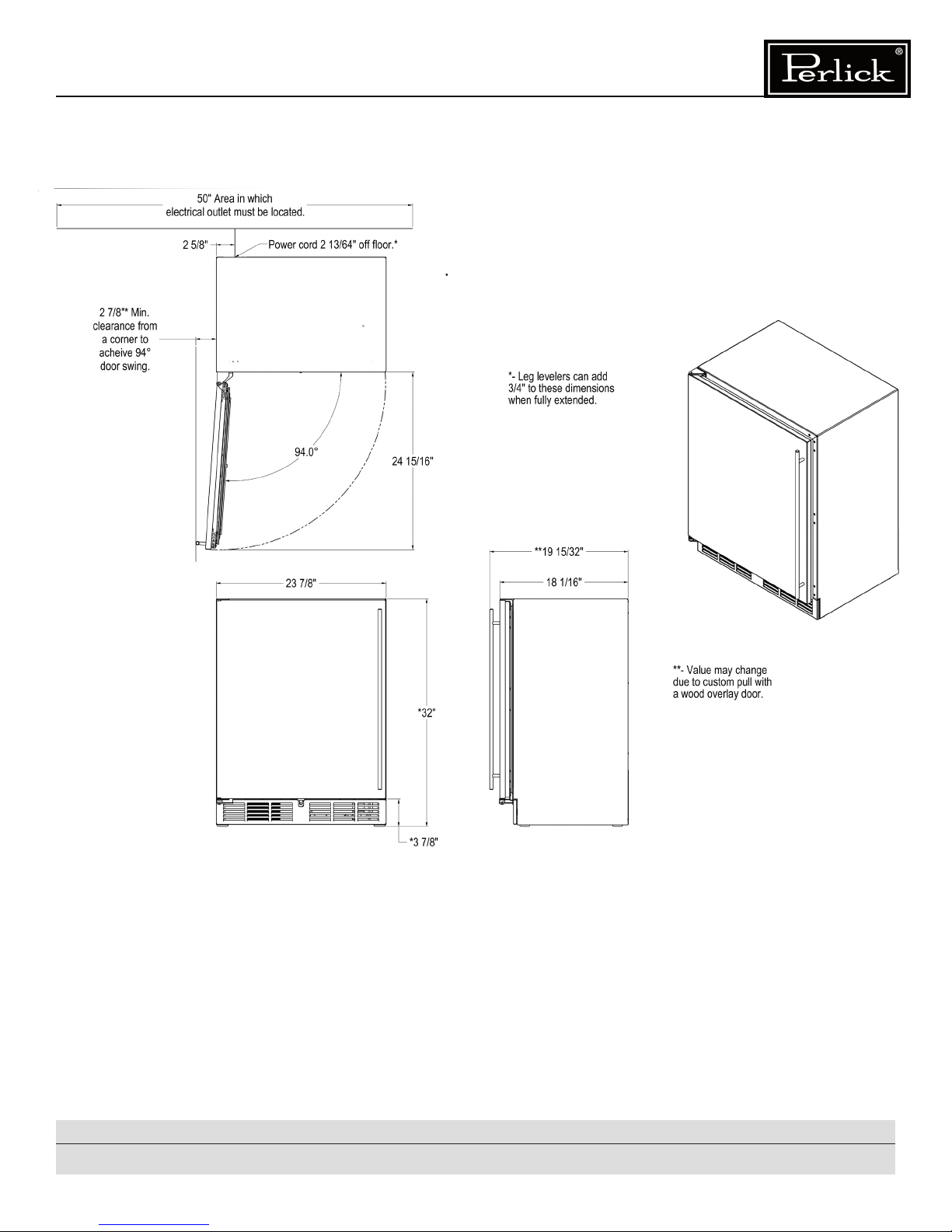
Figure 1. Dimensions
3
Form No.Z2325
Page 4
18” SHALLOW-DEPTH SERIES
18” SHALLOW-DEPTH SERIES
Operation/Installation Manual
Operation/Installation Manual
PREPARING THE SPACE
Make sure the installation opening is properly
prepared. Refer to Figure 1 (page 3) for space
dimensions.
CAUTION
If unit is to be installed under a countertop,
it is recommended that the countertop be
supported by a structure other than the unit
itself, to prevent damage to the countertop.
IMPORTANT: For a cabinet door to operate
properly, the door must be open a minimum of
94° (see Figure 1). Use a minimum 3-3/32” filler in
corner installations to ensure a 94° opening. Allow
enough clearance in front of the unit for full door
swing or shelf pull-out.
IMPORTANT: Make sure floor under unit is level
with the surrounding finished floor. Protect finished
floor with plywood, rug, cardboard or some other
suitable material before moving the unit into place.
Failure to do this may result in damage to the floor.
DANGER
ELECTROCUTION HAZARD!
Electrical grounding required. This appliance
is equipped with a 3-prong (grounding)
polarized plug for protection against possible
shock hazards.
1. Never remove the round grounding prong
from the plug.
2. Never use a 2-prong grounding adapter.
3. Never use an extension cord to connect
power to the unit.
If a 2-prong wall receptacle is encountered,
or a longer power cord is required, contact
a qualified electrician to install the proper
3-prong receptacle in accordance with
applicable electrical codes.
DANGER
Failure to comply with the above electrical
guidelines may result in possible injury/death/
fire or loss of property.
PREPARING ELECTRICAL
CONNECTIONS
A 115 volt, 60Hz, 15 amp circuit breaker and
electrical supply are required. A separate circuit is
recommended.
Follow the National Electrical Code along with
local codes and ordinances when installing the
receptacle.
All Perlick units come equipped with a NEMA
5-15P, 90° plug with a 5’ cord (minimum) extending
beyond the rear of the unit. The electrical outlet
must be flush with, or recessed into, the back wall
or located where the recess is on the back of the
cabinet (Figure 2).
Perlick is committed to continuous improvement. Therefore, we reserve the right to change specications without prior notice
Form No. Z2325
Recessed
Panel
Figure 2. Electrical Connections
4
Page 5
18” SHALLOW-DEPTH SERIES
Operation/Installation Manual
UNPACKING AND MOVING THE UNIT
CAUTION
Do not cut cardboard sleeve covering the unit.
Cutting may result in damage to the exterior of
the unit.
1. Uncrate the unit on a flat level surface. Remove
the cardboard sleeve by removing the banding
holding the sleeve to the shipping base.
Carefully lift the cardboard sleeve up over the
top of the cabinet.
2. Carefully lift unit off base onto a hand truck or
dolly (this should be done with a minimum of two
people, larger cabinets may require additional
helpers). Make sure unit it is balanced on
transporting device. Secure unit to transporting
device using soft flexible strapping. Protect
cabinet surfaces with cloth material where
strapping contacts the unit.
3. Before moving unit, secure door to unit with
tape to hold the door closed.
ANTI-TIP BRACKETS
WARNING
Unit may tip forward if loaded racks/shelves
are all pulled out at the same time. To prevent
tipping and provide a stable installation, the
unit must be secured in place with the anti-tip
brackets provided with the unit.
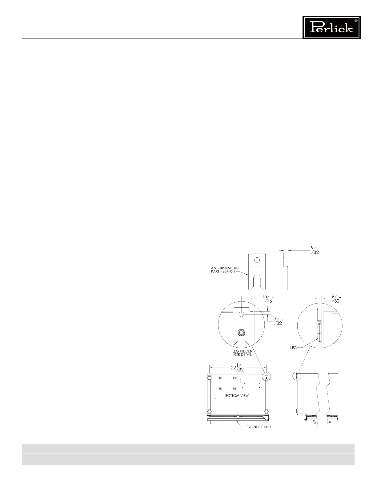
A set of metal anti-tip brackets are supplied with the
unit. The anti-tip brackets, when properly installed,
should secure the rear legs and prevent the unit
from tipping forward. Select fasteners based on
the material the brackets will be fastened to.
Some installation sites may require modification
to provide a secure surface for attaching the
brackets. Refer to Figure 3 for mounting bracket
locations.
IMPORTANT: If installing on a concrete floor,
concrete fastners are required and are not included
in the Anti-Tip Kit.
Perlick is committed to continuous improvement. Therefore, we reserve the right to change specications without prior notice
Figure 3. Installing Anti-tip Brackets
5
Form No.Z2325
Page 6

18” SHALLOW-DEPTH SERIES
18” SHALLOW-DEPTH SERIES
Operation/Installation Manual
Operation/Installation Manual
INSTALLATION
CAUTION
Finished flooring should be protected with
appropriate material to avoid damage from
moving the unit.
If unit is built into cabinetry, allow clearance for
unit to be removed from opening for potential
service requirements.
If unit has been laid on its back or sides, place
unit upright and allow minimum of 24 hours
before connecting power.
1. Plug the unit into the 15 amp grounded outlet
located in the installation opening. With power
applied to the unit, check that lighting and
cooling function operate properly, then turn off
power to the wall outlet at the circuit breaker.
WARNING
Shut off power to the wall outlet before
installing unit into the opening.
2. Check that the following are level and square:
- front face and interior opening
- installation opening and floor surface
- countertop bottom front edge
IMPORTANT: Leveling legs should not extend
more than 3/4” from bottom of unit.
4. Slide unit into position. Make sure the rear
levelling legs slide under the anti-tip brackets.
Push the unit into the opening until the door
is flush with the surrounding cabinetry, or
until the rear legs are tight against the anti-tip
brackets.
IMPORTANT: The rear levelling legs must be
engaged under the anti-tip brackets.
5. Shim the front of the unit so the front door is
flush with the surrounding cabinetry. Adjust
the front legs to support the countertop at
the shimmed height. Using an adjustable
wrench or pliers, turn legs counterclockwise
to raise the unit or clockwise to lower the unit.
Countertop should be resting on top of the unit.
IMPORTANT: The rear levelling legs must be
engaged under the anti-tip brackets.
CAUTION
The prevent damage to the countertop and
unit underneath, do not place heavy objects
on countertop directly above the unit.
IMPORTANT: The floor under the unit must be at
the same level as the surrounding finished floor.
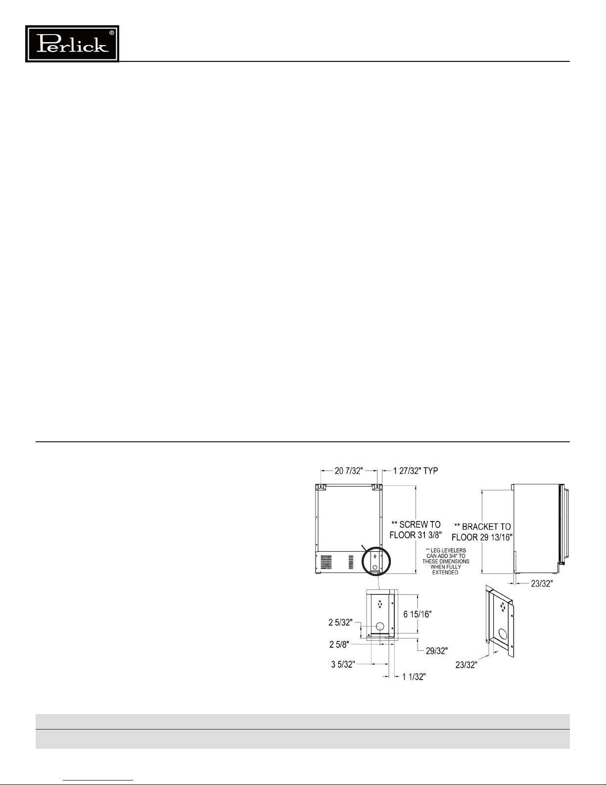
3. If all surfaces are level, refer to Figure 3 and
perform the following:
A. Measure from the floor to the bottom of the
front edge of the countertop.
B. Measure the rear of unit cabinet from floor to
top of cabinet, at back corners.
C. Adjust rear legs so B measurement equals A
measurement. Using an adjustable wrench
or pliers, turn legs counterclockwise to raise
the unit or clockwise to lower the unit.
Perlick is committed to continuous improvement. Therefore, we reserve the right to change specications without prior notice
Form No. Z2325
6. Check interior door openings inside unit to
ensure unit is level.
6
Page 7

18” SHALLOW-DEPTH SERIES
Operation/Installation Manual
Figure 4. Wall Bracket
Perlick is committed to continuous improvement. Therefore, we reserve the right to change specications without prior notice
7
Form No.Z2325
Page 8

18” SHALLOW-DEPTH SERIES
18” SHALLOW-DEPTH SERIES
Operation/Installation Manual
Operation/Installation Manual
SHELVING
IMPORTANT: To achieve maximum performance,
interior louver openings and fan guard should
never be obstructed.
Refrigerator
The single door unit comes standard with black
vinyl coated adjustable full extension pullout
shelves.
Wine Reserve
The single door unit comes standard with four full
extension black vinyl coated wine racks capable
of storing 20 standard wine bottles. Shelves are
removable and/or adjustable. At the bottom, up to
2 1.5L bottles can be stored.
ADJUSTING FULL EXTENSION SHELVING
1. Pull the shelf out to its farthest position. Locate
the tabs in the middle of both extends (Figure
5). Press tabs and pull shelf out.
DOOR PANEL OPTIONS
Perlick units offer a variety of door panel design
alternatives; solid stainless steel, stainless steel
glass, black vinyl (glass or solid door) or laminate.
Solid stainless steel and stainless steel glass
doors are shipped from the factory with decorative
stainless steel panels and handles in place on the
appliance.If optional door lock is ordered, the unit
comes pre-assembled from the factory. Laminate
is also available in a variety of colors and patterns,
and is installed at the factory.
If ordered with the optional door lock, see Figure 6.
Door Lock Installation on page 9.
IMPORTANT: Glass doors may sweat in conditions
with relative humidity over 75%.
2. Reposition each bracket separately. Grasp the
middle of the bracket, pull the front end up and
out, then forward to remove (Figure 5).
3. Place bracket at the desired position. Push
the rear hook into the rear key slot. Set front of
bracket on the wall hook.
4. Repeat for other bracket(s).
5. Push extenders completely into the unit. Align
the shelf grooves with the extenders and slide
completely into the unit.
Press tabs and pull shelf out
Lift this end up
Figure 5. Adjusting the Shelving
Perlick is committed to continuous improvement. Therefore, we reserve the right to change specications without prior notice
Form No. Z2325
8
Page 9

Lock
Bracket
Nut
Lock Strike
Lock Washer
Screw
Body
18” SHALLOW-DEPTH SERIES
Bracket
Nut
Lock Strike
Lock Washer
Operation/Installation Manual
Figure 6. Door Lock Installation
Lock
Bracket
Screw
1. Attach bracket to wood overlay
2. Insert lock body
3. Add and tighten nut
4. Add lock strike
5. Add lock washer and screw
6. Use key to turn the lock and verify that the lock and unlock positions of the strike are correct
(unlock should be up) (lock should be horizontal)
7. Adjust lock if necessary
8. Attached overlay with lock assembly to the door assembly
9. Attach lock bracket to unit
Perlick is committed to continuous improvement. Therefore, we reserve the right to change specications without prior notice
9
Form No.Z2325
Page 10

18” SHALLOW-DEPTH SERIES
18” SHALLOW-DEPTH SERIES
Operation/Installation Manual
C
O
O
L
E
R
Operation/Installation Manual
OPERATION
General
The unit is equipped with a state-of-the-art
refrigeration system and is a frost-free model. The
evaporator coil automatically defrosts on demand
during off cycle.
Interior Light
The unit is equipped with an interior light that
illuminates when the door is opened. A manual
switch is located next to light for displaying the
product through a glass door. Always ensure
the manual switch is in the off position before
closing a solid door. If manual switch is left on for
an extended period of time, it may increase the
cabinet temperature, especially at the top, and
cause the refrigeration system to run longer.
Loading Product
IMPORTANT: When loading items into unit, do
not block interal louvers and fan guard openings
or performance will be decreased.
Temperature Control
The controller is located at the top rear panel of
the cabinet (Figure 7). Approximate temperature
operating ranges are:
■ Refrigerator: 33°F minimum, 39°F maximum
■ Wine Reserve: 40°F minimom, 65°F maximum
Adjusting the Temperature
■ Colder Temperature: Turn the adjusting screw
clockwise (to the right)
■ Warmer Temperatures: Turn the adjusting scrw
counterclockwise (to the left)
■ Temperature Control “OFF”: Turn the adjusting
screw completely counterclockwise to the
“OFF” position until a click is heard.
The condenser fan and motor turns off and on with
the compressor.
4
3
2
1
OFF
Figure 7. Control Panel
5
6
COLD
Perlick is committed to continuous improvement. Therefore, we reserve the right to change specications without prior notice
Form No. Z2325
10
Page 11

18” SHALLOW-DEPTH SERIES
Operation/Installation Manual
Checking Product Temperature
To accurately check the temperature of the product
stored in a refrigerated compartment, insert an
accurate thermometer into a sealable plastic (nonbreakable) bottle, partially filled with water. Tighten
the cap securely.
Place the bottle into the desired area for 24 hours.
Refrain from opening the unit during testing period.
After 24 hours, check the temperature of the water.
Adjust the control settings if necessary and re-test.
The units are pre-set to achieve the recommended
temperature range when installed in a 70°F
ambient environment. Factors which affect the
internal temperatures of the cabinet include the
following:
■ Temperature setting
■ Room temperature where installed
■ Number of times the door is opened and
closed
■ Length of time door is left opened
■ Adjacent compartment temperature
MAINTENANCE
WARNING
Shut off the electricity to the unit before
cleaning the condenser and other routine
maintenance.
Cleaning
To clean stainless steel exterior or interior surfaces,
use a soft, non-abrasive stainless steel cleaner to
wipe down the surfaces.
Glass doors can be cleaned using any standard
glass cleaner available on the market.
To clean interior non-metallic surfaces and
removable parts, wash with a mild solution of
soap and lukewarm water with a little baking soda.
Rinse and dry thoroughly. Avoid getting water on
lights, control panel, and fan motor.
CAUTION
Do not use abrasive cleaners or cloths on any
of the interior or exterior surfaces or removable
parts.
■ Style of door installed
■ Door gasket and sealing
■ Amount of time internal light is illuminated
■ Installation in direct sunlight or near a heat
source.
Perlick is committed to continuous improvement. Therefore, we reserve the right to change specications without prior notice
Cleaning the Condenser
The condenser should be cleaned every three
months. The condenser is located behind the toe
plate. Remove the toe plate and use a soft bristle
brush and vacuum to remove dust and lint. Avoid
damaging or crushing the condenser fins or tubing.
Upon completion, re-install the toe plate.
CAUTION
Failure to clean the condenser could result in
temperature loss or mechanical failure. Clean
this area every three months.
11
Form No.Z2325
Page 12

18” SHALLOW-DEPTH SERIES
18” SHALLOW-DEPTH SERIES
Operation/Installation Manual
Operation/Installation Manual
TROUBLESHOOTING
If the unit appears to be malfunctioning, read through the OPERATION section first, then check the
guide below to identify and resolve the problem.
DANGER
Electrocution hazard! Never attempt to repair or perform maintenance on the unit until the main
electrical power has been disconnected.
No interior light
■ Is the bulb loose?
■ Is the bulb burned out?
Light stays on when the door is closed
■ Manual ON/OFF light switch is turned on.
■ Is the door switch making contact with the plunger?
Noisy during operation
■ Certain sounds are normal. Soft sounds from the compressor, fan motor and valves will be heard.
The refrigerated cabinet isn’t running
■ Is there electrical power to the unit?
■ Is the building circuit breaker/fuse on?
■ Is the control set properly?
■ In the condenser area clean?
The refrigerated compartment is warmer than usual
■ Is the control set properly?
■ Is the light staying on?
■ Is the condenser area clean and free of obstruction?
■ Has the door been open for a long time or more frequent door openings occurred?
■ Are the internal louvers and fan guard openings obstructed?
The refrigerated compartment is cooler than usual
■ Is the control set properly?
■ Is the door closing and sealing properly?
The refrigeration runs for long periods of time
■ Is the condenser area clean and free of obstruction?
■ Has the door been open for a long period of time or more frequent door openings occurred?
■ Has warm product just been placed in the unit?
■ On hot days and in warm room temperatures, the system will run longer.
Condensation forms inside the refrigerated compartments
■ This is normal during high humidity and frequent door openings.
■ Are the doors closing and sealing properly?
Perlick is committed to continuous improvement. Therefore, we reserve the right to change specications without prior notice
Form No. Z2325
12
Page 13

18” SHALLOW-DEPTH SERIES
Operation/Installation Manual
Condensation forms on the outside of the unit
■ During periods of high humidity, some condensation might appear on the outside surface. The
condensation will disappear when the humidity drops. Meanwhile, be sure doors are closing
and sealing properly. If condensation persists, contact your Perlick Factory Authorized Service
Center.
To obtain product information
■ Contact your selling dealer
■ Inquire on the web at www.perlick.com
■ Call 800/558-5592 for factory assistance for planning, installation or product information.
■ Write Perlick Corporation, Customer Service Department,
8300 W. Good Hope Rd., Milwaukee, WI 53223
■ E-mail us at warrantyserv@perlick.com
To obtain product service, replacement parts or accessories
■ Use only genuine Perlick replace parts and accessories. Genuine Perlick parts and accessories
are designed to work correctly with Perlick products and offer superior service life. The use of
non-Perlick parts can damage the unit and may void the warranty.
■ Check the model and serial number of the unit located on the label attached to the inside top
of the cabinet. Call a Perlick Factory Authorized Service Center. For the location of the nearest
Service Center, contact your dealer, or inquire via the web at www.perlick.com, or write to: Perlick
Corporation, Customer Service Department, 8300 W. Good Hope Rd., Milwaukee, WI 53223
Perlick is committed to continuous improvement. Therefore, we reserve the right to change specications without prior notice
13
Form No.Z2325
Page 14

NOTES
NOTES
Perlick is committed to continuous improvement. Therefore, we reserve the right to change specications without prior notice
Form No. Z2325
14
Page 15

NOTES
Perlick is committed to continuous improvement. Therefore, we reserve the right to change specications without prior notice
15
Form No.Z2325
Page 16

erlick
Generations of Excellence
P
8300 West Good Hope Road • Milwaukee, WI 53223 • Phone 414.353.7060 • Fax 414.353.7069
Toll Free 800.558.5592 • E-Mail perlick@perlick.com • www.perlick.com
Form No. Z2325
 Loading...