

Page 1
Installation and Operation Instructions
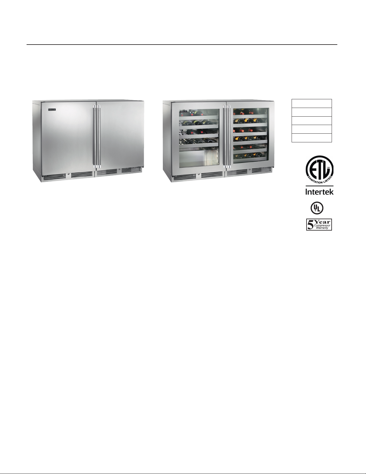
48” Commercial Two Door and Dual-Zone Refrigerator/Wine Reserve
MODEL NO.
HC48RS
HC48WS
HC48RW
HC48WW
Refrigerator
HC48WS
IMPORTANT INFORMATION
This manual has been prepared to assist in the installation of
your Two Door Refrigerator and to acquaint you with its operation and maintenance.
We dedicate considerable time to ensure that our products
provide the highest level of customer satisfaction. If, however service is required, call Perlick at 1-800-777-7267 or your
dealer who can provide you with a list of qualied service
agents. For your own protection, never return merchandise for
credit without our approval.
We thank you for selecting a Perlick product and assure you of
our continuing interest in your satisfaction.
IMPORT WARRANTY INFORMATION
To register your product, visit our web site at
(www.perlick.com). Click on “Bar & Beverage Equipment”,
then “Service & Support”. You will see the link to
Warranty Registration Form”. You must complete and submit
this form or the installation date will revert back to the
ship date.
Dual Zone Wine Reserve
HC48WW
C
US
Table of Contents
Cabinet Specications .......................................2
Cabinet Drawings ..................................................3
Preparing the Cabinet
Uncrating and Inspection ................................4
Plumbing ..........................................................4
Electrical ...........................................................4
Installing Casters or Legs ......................................4
Placing the Cabinet ...............................................4
Anti-Tip Setup ...................................................4
Sealing the Cabinet ..........................................5
Shelving ............................................................6
Adjusting Full Extension Shelving ..................6
Safety ......................................................................7
Operation ...............................................................7
Checking Product Temperature ............................7
Programming Button Denitions.........................7
HC48 Control Instructions ....................................8
LED Functions ........................................................8
Maintenance ..........................................................9
Troubleshooting ................................................. 10
Wiring Diagram ................................................... 11
Page 2

PRODUCT CUTSHEETS Refrigerated Cabinets
48” TWO DOOR AND DUALZONE
REFRIGERATOR/WINE RESERVE
JOB
AREA
ITEM NO.
MODEL NO.
*
MODEL NO.
HC48RS
HC48WS
HC48RW
Refrigerator
HC48WS
MODEL NO. HC48RS HC48WS HC48RW HC48WW
CABINET
DIMENSIONS
SHIP WEIGHT LBS. (KG) 375 (170) 375 (170) 375 (170) 375 (170)
CAPACITY CU. FT. (L.) 11.7 (331) 11.7 (331) 11.1 (314) 11.1 (314)
SHELVING 2 black vinyl-coated full-exten-
TEMPERATURE SETTINGS F°(C) Range 32°F (0°) - 42°F (5.6°)
TAPPING Centered over door
CABINET CONSTRUCTION (INT.) Interior Stainless Steel
CABINET CONSTRUCTION (EXT.) Exterior Sides, Exterior Top and Grill Stainless Steel Exterior Back and Exterior Bottom Stainless Steel
CABINET INSULATION Polyurethane-Ecomate. Wall Thickness-2” Door Thickness-2”
DOORS, HINGING & HARDWARE
CONDENSING UNIT H.P. 1/6 Condenser Access Front
REFRIGERATION Refrigerant 9.0 oz. - R134a Expansion Device Capillary Tube Type w/Hermetic Compressor
PLUMBING None required. Moisture drains to self evaporating condensate pan
ELECTRICAL Electrical Supply 115V/60 Hz/1 Phase Running Load Amps 2.8 Cord Connection Cord Connected (3-prong
VENTILATION
Length Ins. (mm) 47-7/8” (1216) 47-7/8” (1216) 47-7/8” (1216) 47-7/8” (1216)
Depth Ins. (mm) 24” (610) 24” (610) 24” (610) 24” (610)
Height Ins. (mm) 34-3/8” (873) 34-3/8” (873) 34-3/8” (873) 34-3/8” (873)
sion shelves (adjustable) per
door & oor racks
Factory Set Point
36°F (2.2°)
compartment 2 only.
Door Exterior Customer Choice (see below under ‘Customer Options’)
Number of Doors 2 Opening Style Hinged (Left or Right) Door Style Solid or Glass
Door Swing Clearance 25” (635) Locks Available (factory installed)
6’ NEMA 5-15P) Thermostat Digital Lighting Type LED blue/white
Front-vented
Dual Zone Wine Reserve
HC48WW
4 full-extension wine
shelves & 6 full-extension wine shelves.
Magnum oor rack 1st
compartment.
40°F (4.4°) - 68°F (20°)
Factory Set Point
43°F (6.1°)
Wine tapping not
available.
2 black vinyl-coated
full-extension shelves
(adjustable) & 6 full
extension wine shelves
32°F (0°) - 42°F (5.6°)
40°F (4.4°) - 68°F (20°)
Factory Set Point
36°F (2.2°)
43°F (6.1°)
Wine tapping not
available.
C
US
HC48WW
4 full-extension wine
shelves & 6 full-extension
wine shelves. Magnum
oor rack 1st compartment.
43°F (6.1°)
54°F (12.2°)
Factory Set Point
40°F (4.4°) - 68°F (20°)
40°F (4.4°) - 68°F (20°)
Wine tapping not
available.
*NOTE: This equipment is intended for the storage and display of
non-potentially hazardous bottled or canned products only!
8300 West Good Hope Road • Milwaukee, WI 53223 • Phone 414-353-7060 • Fax 414-353-7069
Toll Free 800-558-5592 • E-mail: Perlick@Perlick.com • Perlick.com
2
Form No. Z2426
03.22.16
Page 3
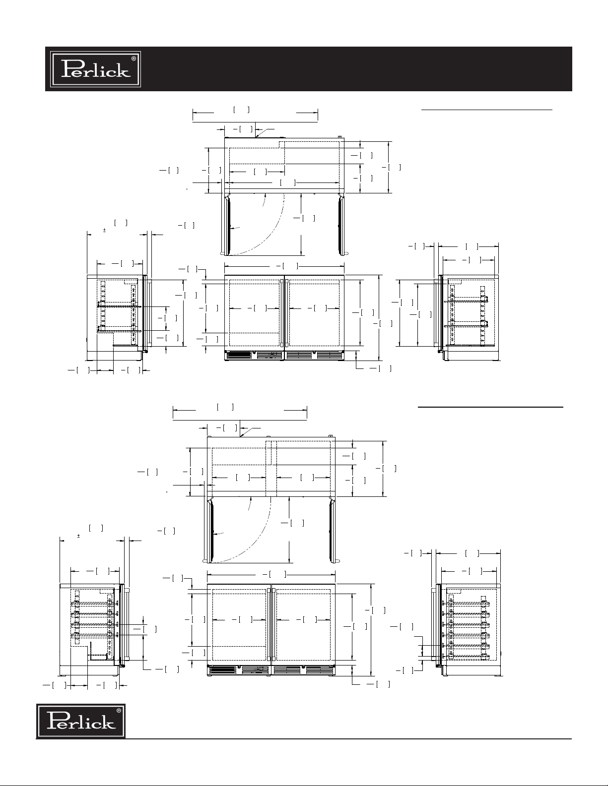
PRODUCT CUTSHEETS Refrigerated Cabinets
when fully extended
HC48RW& HC48WW MODELS
when fully extended
48” TWO DOOR AND DUALZONE
REFRIGERATOR/WINE RESERVE
(with 1/16" tolerance)
wood overlay door.
7
"
164
16
24" 611
Value may
change with a
3
18
" 462
16
3
"
11
4
2986
3
"
1
30 Min.
16
clearance from
a corner to
acheive 90
door swing.
3
1
" 44
4
Value may
change due to a
custom pull.
9
1
16
9
26
"
16
5
9
245
"
8
3
6
" 158
16
50" 1270 Area in which
electrical outlet must be located.
12
1
18
" 460
8
" 40
674
5
19
" 498
8
3
5
" 132
16
1
" 311
4
90° Swing
required for
pull-out shelf
clearance.
19
Power cord 8-1/4" [210] off floor.*
22" 559
44" 1118
7
7
" 504 19
8
* - Leg leveler can add
3/4" [19] to these dimensions
15
24
" 634
16
Min. clearance
for door swing.
"4781216
7
8
" 504
HC48RS & HC48WS MODELS
7
6
" 164
16
11
26
3
4
7
16
" 298
" 671
*34 " 873
*4
5
20
523
"
8
3
1
" 44
4
9
26
674
"
16
15
24
" 634
3
8
1
" 103
16
16
24" 611
5
20
" 523
8
Shelves adjustable by 2" [51].
RELEASE FOR PRODUCTION
A
1/28/2016
REVISIONS
SCALE: 1:12
JMP
(with 1/16" tolerance)
wood overlay door.
7
6
" 164 11
16
24" 611
Value may
change with a
3
18
" 462
16
3
" 298
4
3
1
" 30 Min.
16
clearance from
a corner to
acheive 90
door swing.
3
1
4
Value may
change due to a
custom pull.
1
15
3
" 100
16
7
9
16
" 44
9
16
" 240
50" 1270 Area in which
electrical outlet must be located.
1
12
" 311
4
1
18
" 460
8
pull-out shelf
" 40
5
19
" 498
8
3
5
" 132
16
Power cord 8-1/4" [210] off floor.*
20" 50820"
508
90° Swing
required for
clearance.
7
19
" 504 19
8
* - Leg leveler can add
3/4" [19] to these dimensions
15
24
16
Min. clearance
for door swing.
7
"4781216
" 634
7
8
" 504
67"16164
3
11
" 298
4
13
24
16
*34 " 873
" 630
*4
5
" 52320
8
3
1
" 44
4
3
8
15
3
" 100
16
Typical
Wine Shelf
Spacing
1
1
" 39
2
1
" 103
16
24" 611
5
20
" 523
8
Shelves adjustable by 2" [51].
RELEASE FOR PRODUCTION
A
1/28/2016
REVISIONS
SCALE: 1:12
JMP
8300 West Good Hope Road • Milwaukee, WI 53223 • Phone 414-353-7060 • Fax 414-353-7069
Toll Free 800-558-5592 • E-mail: Perlick@Perlick.com • Perlick.com
Form No. Z2426
3
03.22.16
Page 4

Preparing the Cabinet
Uncrating and Inspection
Remove all crating material before operating. Carefully
inspect cabinet for hidden damage. If damage is discovered,
le your claim immediately with the transport company.
Perlick is not responsible for damage in transit.
Plumbing
No plumbing connections are required. Condensate from
the cooling coil is automatically evaporated through a condensate pan located in the condensing unit section.
Electrical
The cabinet must be connected to a separately fused power
source (see Electrical Specication Plate) and grounded in
accordance with National and Local Electrical Codes.
CAUTION: Do not attempt to operate the equipment on
any other power source than that listed on the Electrical
Specication Plate.
Installing Casters or Legs (optional)
Remove existing cabinet glides. Attach bracket assembly
to the bottom of the cabinet base using the 1/4”-20 Phillips head machine screws provided. Attach casters or legs
to the mounting bracket with 1/4” - 20 Phillips head screws
provided.
NOTE: To comply with NSF requirements, cabinet must be
sealed to oor or on legs, casters or rollers.
Placing the Cabinet
To assure maximum performance, fresh air must be allowed
to circulate through the machinery compartment. Do not
place anything in front of the cabinet that would obstruct air
ow at these grilles. Do not place the unit in an unventilated
small room.
Cabinet should be leveled front to back and side to side.
Anti-tip (without Legs, Casters or Rollers)
To prevent the cabinet from tipping forward and to provide
a stable installation, the cabinet must be secured in place
with an anti-tip device.
A set of metal anti-tip brackets are supplied. These brackets
should be attached to the oor, at the back of the cabinet;
each bracket located to catch each rear glide when the cabinet is pushed back into position.
THE ANTITIP BRACKETS MUST CATCH EACH OF THE
GLIDES TO HAVE A STABLE AND SAFE INSTALLATION.
Some installation sites might need to be modied to provide
a secure surface for attaching the bracket. Refer to the illustration below for anti-tip mounting bracket locations.
⁄”
⁄”
22-⁄” 23-⁄”
⁄”
Figure 3. 48” Anti-tip Kit
8300 West Good Hope Road • Milwaukee, WI 53223 • Phone 414-353-7060 • Fax 414-353-7069
Toll Free 800-558-5592 • E-mail: Perlick@Perlick.com • Perlick.com
½“ to hole
4
1-¾”
⁄”
Form No. Z2426
03.22.16
Page 5

Preparing the Cabinet
Sealing the Cabinet
For sanitation purposes, it may be necessary to seal the
base of the cabinet to the oor. This can be accomplished
by laying a bead of silicone sealant between the base of the
cabinet and the oor as shown by the gure below.
When sealing the cabinet to the oor, make sure that the
louvered front grille plate can still be removed for condenser
maintenance and cleaning.
CAUTION: Finished ooring should be protected with
appropriate material to avoid damage from moving
the unit.
If unit has laid on its back or sides, place unit upright and
allow minimum of 24 hours before connecting power.
Plug the unit into the 15 amp grounded outlet located in the
installation opening. With power applied to the unit, check
that lighting and cooling function operate properly, then
turn o power to wall outlet at the circuit breaker.
CAUTION: To prevent damage to the counter top and
unit underneath, do not place heavy objects on the
counter top directly above the unit.
Check interior door openings inside unit and ensure unit
is level.
8300 West Good Hope Road • Milwaukee, WI 53223 • Phone 414-353-7060 • Fax 414-353-7069
Toll Free 800-558-5592 • E-mail: Perlick@Perlick.com • Perlick.com
5
Form No. Z2426
03.22.16
Page 6

Preparing the Cabinet
Shelving
IMPORTANT: To achieve maximum performance, interior
louver openings and fan guard openings should never be
obstructed.
Refrigerator:
The refrigerator compartments come standard with black
vinyl coated adjustable full extension pullout shelves.
Wine Reserve:
The two door unit comes standard with 4 full extension
wine shelves and six full extension black vinyl coated wine
shelves. The shelves are removable and adjustable to accomodate oversized (magnum) bottles.
Adjusting Full Extension Shelving
• Pull the shelf out to its furthest position. Locate the tabs
in the middle of both extenders (See Extender Tabs Below).
Press tabs and pull out.
• Reposition each bracket separately. Grasp the middle of
the bracket, pull the front end up and out, then forward to
remove (See Mounting Brackets Below).
• Place bracket at desired position. Push the rear hook into
the rear key slot. Set front of bracket on the wall hook.
• Repeat for other bracket(s).
• Push extenders completely into the unit. Align the shelf
grooves with the extenders and slide completely into
the unit.
Sliding Shelf Extender Tabs
8300 West Good Hope Road • Milwaukee, WI 53223 • Phone 414-353-7060 • Fax 414-353-7069
Sliding Shelf Mounting Brackets
Toll Free 800-558-5592 • E-mail: Perlick@Perlick.com • Perlick.com
6
Form No. Z2426
03.22.16
Page 7

SAFETY
DANGER
WARNING
CAUTION
PLEASE READ all instructions completely before attempting to install or operate the unit. Take particular
note of the DANGER, WARNING and CAUTION information in the manual. The information is important for
the safe and ecient installation, operation and care of
your Perlick unit.
Indicates a hazard that WILL result in serious injury
or death if precautions are not followed.
Indicates a hazard MAY cause serious injury or death
if precautions are not followed.
When loading items into the unit, do not block internal
louvers and fan guard openings or performance will be
decreased.
CHECKING PRODUCT TEMPERATURE
1). To accurately check the temperature of product
stored in the refrigerated compartment, insert an
accurate thermometer into a plastic unbreakable
bottle, partially lled with water. Tighten bottle cap
securely.
2). Place the bottle in the desired area for 24 hours.
Refrain from opening the unit during the testing
period. After 24 hours, check the temperature of the
water. Adjust the temperature accordingly using the
following procedures:
Indicates a hazard where minor injury or product
damage may occur if precautions are not followed.
OPERATION
MASTER SWITCH
These products come equipped with a master power
switch located behind the louvered toe kick. Remove
the toe kick to turn power on or o to the unit.
INTERIOR LIGHT
Units are equipped with an interior light that illuminate
when the door is opened. All HC48 models come
standard with adjustable blue and white LED lighting.
The cabinet also comes equipped with a manual light
switch for displaying the products through a glass
door.
Always ensure that the manual light switch is in the
OFF position before closing a solid wood or stainless
steel door. If manual light switch is left on for an
extended period of time, it may increase the cabinet
temperature, and cause the refrigeration system to run
harder.
DIGITAL TEMPERATURE CONTROL
HC48 Models
Figure 1. Digital Temperature Controller
Programming Button Denitions:
SET button
DEFROST button (melting snowake)
UP arrow
DOWN arrow
ON/OFF button
LOADING PRODUCT
Before storing perishables, turn unit on and allow
it to operate for a minimum of 24 hours to allow
temperatures to stabilize.
8300 West Good Hope Road • Milwaukee, WI 53223 • Phone 414-353-7060 • Fax 414-353-7069
Toll Free 800-558-5592 • E-mail: Perlick@Perlick.com • Perlick.com
7
Form No. Z2426
03.22.16
Page 8

HC48 Control Instructions
HC48 Control Instructions
To Set Target Temperature
Press and release the SET button. Display will show the
current temperature setpoint.
To Change Setpoint Temperature
1. Press and hold the SET button until the display
shows the current setpoint temperature with the “F”
ashing.
2. Use the UP and DOWN arrow button to scroll to the
desired temperature.
To Set Maximum Stored Temperature
Press the UP arrow button to see the maximum stored
temperature. To reset the maximum stored temperature, while displayed, press and hold the SET button
until ‘rst’ ashes in the display.
To Set Minimum Stored Temperature
Press the DOWN arrow button to see the minimum
stored temperature. To reset the minimum stored
temperature, while displayed, press and hold the SET
button until ‘rst’ ashes in the display.
Signature Series – HC48RS Models
Model Min Temp Set Max Temp Set
HC48RS 36° F (2.2°) 42°F (5.6°)
Signature Series – HC48WS Models
Model Min Temp Set Max Temp Set
HC48WS 40° F (4.4°) 68° F (20°)
Signature Series – HC48RW Models
Model Min Temp Set Max Temp Set
HC48RW Left 32° F (0°)
Right 40° F (4.4°)
Signature Series - HC48WW
Model Min Temp Set Max Temp Set
HC48WW 43° F (6.1°) 54° F (12.2°)
NOTE: The colder temperature setting must always be
applied to the compartment on the left. A minimum
temperature dierence of 6° between the left and right
compartments is required.
Example: 42° Left compartment and 48° right compartment
is achievable. 40° Left compartment and 44° right
compartment is not achievable.
Left 42° F (5.6°)
Right 68° F (20°)
On/O
Press the ON/OFF button to turn the unit on or o.
Key Combinations:
+
Press the UP and DOWN arrow
buttons to lock and unlock the
keyboard
+
Press the SET and DOWN arrow
buttons simultaneously to enter
programming mode.
+
Press the SET and UP arrow buttons simultaneously to return to
room temperature display.
NOTE: Dependent on the model and conguration, the
controllers have been programmed to only allow a temperature
adjustment within a specied range. See the chart top right for
the specied range allowed for your unit.
LED Functions
The following table describes LED functions
LED Mode Function
ON Compressor is on
Flashing Anti-short cycle
delay is on
ON Defrost is on
ON Alarm is on
Flashing You are in the process of
programming the unit
8300 West Good Hope Road • Milwaukee, WI 53223 • Phone 414-353-7060 • Fax 414-353-7069
Toll Free 800-558-5592 • E-mail: Perlick@Perlick.com • Perlick.com
8
Form No. Z2426
03.22.16
Page 9

Maintenance
WARNING:
Shut o the electricity to the unit before cleaning the condenser and other routine maintenance.
Cleaning:
To clean stainless steel exterior or interior surfaces, use a
soft, non-abrasive stainless steel cleaner to wipe down the
surfaces.
Glass doors can be cleaned using any standard glass cleaner
available on the market.
To clean interior non-metallic surfaces and removable
parts, wash with a mild solution of soap and lukewarm water
with a little baking soda. Rinse and dry thoroughly. Avoid
getting water on lights, control panel, fan motor and unnished wood wine rack faces.
CAUTION:
Do not use abrasive cleaners or cloths on any of the interior
or exterior surfaces or removable parts.
Cleaning the Condenser:
The condenser should be cleaned every 3 months. The condenser is located behind the toe plate. Remove the toe plate
and use a soft bristle brush and vacuum to remove dust and
lint. Avoid damaging or crushing the condenser ns or tubing. Upon completion, re-install the toe plate.
CAUTION:
Failure to clean the condenser could result in temperature loss or mechanical failure. Clean this area every three
months.
Avoiding Stainless Steel Corrosion:
Corrosion can be prevented by following product cautions,
cleaning instructions and avoiding use of certain chemicals
or objects which will cause stainless steel corrosion.
Stainless Steel Enemy:
• Steelwool or steel scouring pads
• Cherry, Orange or Olive Juice
• Chlorine bleach
• Sharp objects
8300 West Good Hope Road • Milwaukee, WI 53223 • Phone 414-353-7060 • Fax 414-353-7069
Toll Free 800-558-5592 • E-mail: Perlick@Perlick.com • Perlick.com
9
Form No. Z2426
03.22.16
Page 10

Troubleshooting
If the unit appears to be malfunctioning, read through the
OPERATION section rst, then check the guide below to
identify and resolve the problem.
PROBLEM RESOLUTION
No interior light
Light stays on when the
door is closed
Noisy during operation
The refrigerated cabinet
isn’t running
The refrigeration compartment is warmer than usual
The refrigerated compartment is cooler than usual
The refrigerations runs for
long periods of time
Condensation forms
inside the refrigerated
Is the bulb loose?
Is the bulb burned out?
Manual ON/OFF light switch is turned on.
Is the door switch making contact with the plunger?
Certain sounds are normal. Soft sounds from the compressor, fan motor and valves will be heard.
Is there electrical power to the unit?
Is the building circuit breaker or fuse on?
Is the control set properly?
Is the condenser area clean?
Is the control set properly?
Is the light staying on?
Is the condenser area clean and free of obstruction?
Has the door been open for a long time or more frequently door opening occurred?
Are internal louvers and fan guard openings obstructed?
Is the control set properly?
Is the door closing and sealing properly?
Is the condenser area clean and free of obstruction?
Has the door been open for a long time or more frequently door opening occurred?
Has warm product just been placed in the unit?
On hot days and in warm room temperatures, the system will
run longer.
This is normal during high humidity and frequent door openings.
Are the doors closing and sealing properly?
compartments
Condensation forms on
the outside of the unit
During periods of high humidity, some condensation might appear on the outside surface. The
condensation will disappear when the humidity drops. Meanwhile, be sure doors are closing and
sealing properly. If condensation persists, contact your Perlick Factory Authorized service center.
DANGER: Electrocution hazard! Never attempt to repair
or perform maintenance on the unit until the main elec-
trical power has been disconnected.
To Obtain Product Information
• Contact your selling dealer.
• Inquire on the web at www.perlick.com.
• Call 800-558-5529 for factory assistance for information,
planning, installation or product information.
• Write Perlick Corporation, Customer Service Department,
8300 W. Good Hope Road, Milwaukee, Wisconsin 53223.
• E-mail us at warrantyserv@perlick.com.
To Obtain Product Service, Replacement Parts
or Accessories:
Use only genuine Perlick replacement parts and accessories.
Genuine Perlick parts and accessories are designed to work
8300 West Good Hope Road • Milwaukee, WI 53223 • Phone 414-353-7060 • Fax 414-353-7069
Toll Free 800-558-5592 • E-mail: Perlick@Perlick.com • Perlick.com
correctly with Perlick products and oer superior service life.
The use of non-Perlick parts can damage the unit and may
void the warranty.
Check the model and serial number of the unit located
on the label attached to the inside top of the cabinet.
Call a Perlick Factory Authorized service center. For the location of the nearest Service Center, contact your dealer, or
inquire via the web at www.perlick.com, or write to:
Perlick Corporation, Customer Service Department,
8300 W. Good Hope Road, Milwaukee, Wisconsin 53223,
call 800-558-5592, or e-mail us at:
warrantyserv@perlick.com.
10
Form No. Z2426
03.22.16
Page 11

HOT KEY
CSP-1
6
COMMON
DEFROST PROBE
ROOM PROBE
XR60CX-D1
101211 78 4 35 12
G
L
N
EFM-1
21
DSW-1
232220
CFM-1
XR60CX-D1--REFRIGERATION SYSTEM CONTROLLER
DSW-1--LIGHT AND EVAP FAN MOTOR DOOR SWITCH
SW-1--MASTER POWER SWITCH
LIGHT BOARD--BLUE&WHITE LED
EFM-1--EVAPORATOR FAN MOTOR
CSP-1--REFRIGERATED COMPARTMENT 1 SENSOR PROBE
COMP-1--COMPRESSOR
BLACK
BLACK
BLACK
BLACK
WHITE
RED
BLUE
WHITE
BLUE
WHITE
WHITE
RED
WHITE
WHITE
BLACK
BLACK
HGS
COMP-1
INV-1
MH-1
INV-1--INVERTER
MH-1--MULLION HEATER (DRAWERS ONLY)
HGS-1--HOT GAS SOLENOID (FRZ ONLY)
SW-2
WHITE-BLUE
BLACK-BROWN
LED DRIVER
RED
RED
BLACK
BLUE
LIGHT BOARD
WHITE
120VAC
12VDC
-
+
SW-1
SW-2--3-WAY LIGHT SWITCH
WHITE
BLACK
NOTE: DRAWER UNITS DO NOT HAVE LIGHTS
HOT KEY
CSP-1
6
COMMON
DEFROST PROBE
ROOM PROBE
XR20CX-D1
101211 78 4 35 12
EFM-2
21
DSW-2
232220
XR20CX-D1--REFRIGERATION SYSTEM CONTROLLER
DSW-2--LIGHT DOOR SWITCH
LIGHT BOARD--BLUE&WHITE LED
EFM-2--COMPARTMENT #2 FAN MOTOR
CSP-2--REFRIGERATED COMPARTMENT 2 SENSOR PROBE
BLACK
BLACK
WHITE
BLUE
BLUE
WHITE
BLACK
SW-3
RED
RED
BLACK
BLUE
LIGHT BOARD
WHITE
12VDC
-
+
SW-3--3-WAY LIGHT SWITCH
WHITE
BLACK
NOTE: DRAWER UNITS DO NOT HAVE LIGHTS
AFM-1
AFM-1--AUX. FAN MOTOR (IF ONE TEMPERATURE ZONE)
NOTE: NO CONTROL OR EFM-2 ON SINGLE ZONE
NOTE: IF 1ST COMPARTMENT DRAWERS (DRIVER IS
LOCATED IN SECOND COMPARTMENT)
DIMENSIONS ARE IN INCHES
Wiring Diagram
TOLERANCES UNLESS OTHERWISE SPECIFIED
8300 West Good Hope Road • Milwaukee, WI 53223 • Phone 414-353-7060 • Fax 414-353-7069
Toll Free 800-558-5592 • E-mail: Perlick@Perlick.com • Perlick.com
11
Form No. Z2426
03.22.16
Page 12

8300 West Good Hope Road • Milwaukee, WI 53223 • Phone 414-353-7060 • Fax 414-353-7069
Toll Free 800-558-5592 • E-mail: Perlick@Perlick.com • Perlick.com
12
Form No. Z2426
03.22.16
 Loading...