

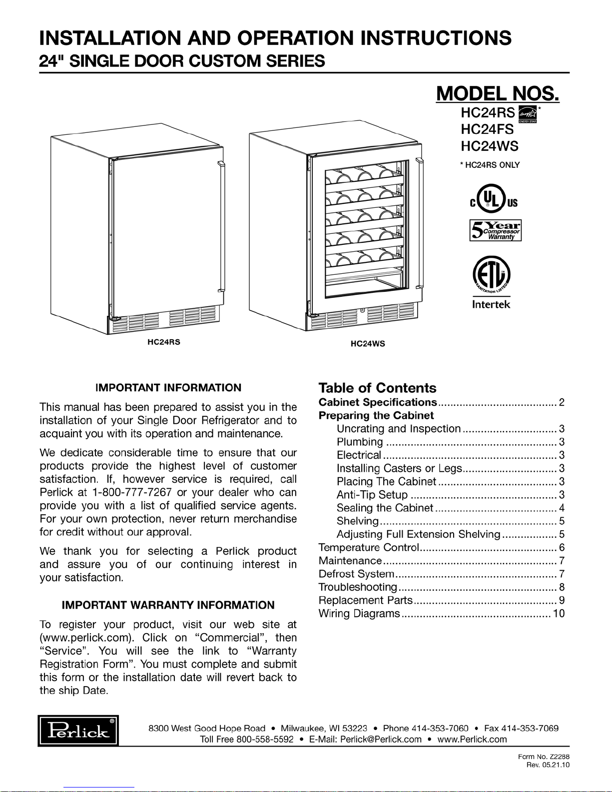
Page 1
Page 2
Installation and Operating Instructions
50” AREA IN WHICH ELECTRICAL
OUTLET MUST BE LOCATED
*41/4” MIN.
CLEARANCE
FROM A CORNER
TO ACHIEVE
REQUIRED
DOOR SWING
*VALUES MAY
CHANGE DUE
TO CUSTOM PULL
WITH A WOOD
OVERLAY DOOR
*255/16”
221/8”
2315/16”
2425/32” MIN.
CLEARANCE
FOR DOOR
SWING
237/8”
34”
319/32”
83/8”
93/8”
71/2”
98° SWING
REQUIRED FOR
PULL-OUT SHELF
CLEARANCE
STANDARD LEVELERS
INCREASE CABINET
HEIGHT 1/4”
REF/FREEZ
Specifications - 24" Custom Series Refrigerator/Froster/Wine Reserve
MODEL NOS. HC24RS HC24FS HC24WS
7
⁄8” (607) 237⁄8” (607) 237⁄8” (607)
15
/16” (608)
Cabinet
Dimensions
Length - Inches (mm) 23
Depth - Inches (mm) 23
Height - Inches (mm) 34” (870) 34” (870) 34” (870)
†
15
23
/16” (608) 23
15
/16” (608)
INTERIOR VOLUME - CUBIC FOOT (m3) 5.3 (0.15) 5.3 (0.15) 5.3 (0.15)
SHELVING 2 Full Extension Shelves 2 Full Extension Shelves 5 Full Extension Wine Racks
CAPACITY* 5 cases 86 glasses 45 wine bottles
TEMPERATURE RANGE 32°F to 42°F (0C to 6C) -10°F to +10°F (-23C to -12C) 45°F to 65°F (7C to 18C)
RUNNING LOAD AMPS 2.3 2.3 2.3
CONDENSING UNIT H.P. 1/6 HP 1/6 HP 1/6 HP
SHIP WT. L
INTERIOR
EXTERIOR
REFRIGERATION
bs. (kg.) 195 (89) 195 (89) 215 (98)
All stainless steel interior.
Stainless steel top, sides and grille, galvanized back and bottom. See door finishes under optional accessories.
R-134a capillary tube-type with hermetric compressor. Front access condenser. Froster equipped with
automatic 4 hour hot gas defrost cycle and manual 6 hour defrost with auto restart.
ELECTRICAL 115V, 60Hz., 1 phase, furnished with 3-prong NEMA 5-15P plug, 6 foot long cord.
PLUMBING None required. Moisture drains to self evaporating condensate pan.
VENTILATION
OPTIONAL
ACCESSORIES &
MODIFICATIONS
Front vented.
• Leg set Customer choice of laminate
• Caster Set Powder coated (color options)**
• Door Lock
Brass hardware (classic, 12" & full length) or pull tab
Door Finishes
Prepared for field lamination
Glass door with black vinyl frame
Glass door with stainless steel frame
Black vinyl coated Glass door with laminated frame
Stainless steel Glass door with powder coated frame**
* Froster - glass size 3” diameter. Refrigerator - 12 oz. long neck bottles. Wine - 750ml wine bottles.
** Call Milwaukee or see our web site for standard or custom color options.
†
HC24RS Only
Form No. Z2288
Rev. 05.21.10
Top View Front View End View
Perlick is committed to continuous improvement. Therefore, we reserve the right to change specifications without prior notice.
2
Page 3
Preparing the Cabinet
15/16”
22 1/32”
Cabinet must
have at least
5/16” clearance
from floor to
accomodate
brackets.
Shown with glide engaged
in anti-tip bracket.
Surface
mounts
to floor.
Ø 3/8”
3/16”
Uncrating and Inspection
Remove all crating material before operating.
Carefully inspect cabinet for hidden damage.
If damage is discovered, file your claim immediately
with the transport company. Perlick is not
responsible for damage in transit.
Plumbing
No plumbing connections are required. Condensate
from the cooling coil is automatically evaporated
through a condensate pan located in the
condensing unit section.
Electrical
The cabinet must be connected to a separately
fused power source (see Electrical Specification
Plate) and grounded in accordance with National
and Local Electrical Codes.
Do not attempt to operate the equipment on
any other power source than that listed on the
Electrical Specification Plate.
CAUTION
:
Anti-tip (without Legs, Casters or Rollers)
To prevent the cabinet from tipping forward and to
provide a stable installation, the cabinet must be
secured in place with an anti-tip device.
A set of metal anti-tip brackets are supplied.
These brackets should be attached to the floor, at
the back of the cabinet; each bracket located to
catch each rear glide when the cabinet is pushed
back into position.
THE ANTI-TIP BRACKETS MUST CATCH EACH
OF THE GLIDES TO HAVE A STABLE AND SAFE
INSTALLATION.
Some installation sites might need to be modified
to provide a secure surface for attaching the bracket. Refer to the illustration below for anti-tip mounting bracket locations.
Installing Casters or Legs (optional)
Remove existing cabinet glides. Attach bracket
assembly to the bottom of the cabinet base using
the 1⁄4”–20 Phillips head machine screws provided.
Attach casters or legs to the mounting bracket with
1
⁄4”–20 Phillips head screws provided.
NOTE: To comply with NSF requirements, cabinet
must be sealed to floor or on legs, casters or
rollers.
Placing the Cabinet
To assure maximum performance, fresh air must
be allowed to circulate through the machinery
compartment. Do not place anything in front of the
cabinet that would obstruct air flow at these grilles.
Do not place the unit in an unventilated small room.
Cabinet should be leveled front to back and side
to side.
Perlick is committed to continuous improvement. Therefore, we reserve the right to change specifications without prior notice.
3
Form No. Z2288
Rev. 05.21.10
Page 4
Preparing the Cabinet
BEAD SILICON
SEALER (RTV)
FLOOR
CABINET
Sealing the Cabinet
For sanitation purposes, it may be necessary to
seal the base of the cabinet to the floor. This can
be accomplished by laying a bead of silicone sealant between the base of the cabinet and the floor
as shown by the figure below.
When sealing the cabinet to the floor, make sure
that the louvered front grille plate can still be
removed for condenser maintenance and cleaning.
CAUTION
:
Finished flooring should be protected with
appropriate material to avoid damage from
moving the unit.
If unit has been laid on its back or sides, place
unit upright and allow minimum of 24 hours
before connecting power.
Plug the unit into the 15 amp grounded outlet
located in the installation opening. With power
applied to the unit, check that lighting and cooling
function operate properly, then turn off power to
wall outlet at the circuit breaker.
CAUTION
:
To prevent damage to the counter top and unit
underneath, do not place heavy objects on the
counter top directly above the unit.
Check interior door openings inside unit and ensure
unit is level.
Form No. Z2288
Rev. 05.21.10
Perlick is committed to continuous improvement. Therefore, we reserve the right to change specifications without prior notice.
4
Page 5

Preparing the Cabinet
Press Tabs and
Pull Shelf Out
Lift This
End Up
Shelving
IMPORTANT: To achieve maximum performance,
interior louver openings and fan guard openings
should never be obstructed.
Refrigerator/Froster:
The single door unit comes standard with black
vinyl coated adjustable full extension pullout
shelves.
Wine Reserve:
The single door unit comes standard with six full
extension black vinyl coated wine racks capable of
storing 48 total wine bottles. Shelves are removable
and adjustable to accomodate oversized (magnum)
bottles.
Adjusting Full Extension Shelving
n Pull the shelf out to its furthest position. Locate
the tabs in the middle of both extenders (See
Extender Tabs Below). Press tabs and pull out.
n Reposition each bracket separately. Grasp the
middle of the bracket, pull the front end up and
out, then forward to remove (See Mounting
Brackets Below).
n Place bracket at desired position. Push the rear
hook into the rear key slot. Set front of bracket
on the wall hook.
n Repeat for other bracket(s).
n Push extenders completely into the unit. Align
the shelf grooves with the extenders and slide
completely into the unit.
Sliding Shelf Extender Tabs
Perlick is committed to continuous improvement. Therefore, we reserve the right to change specifications without prior notice.
Sliding Shelf Mounting Brackets
5
Form No. Z2288
Rev. 05.21.10
Page 6

Operation Instructions
C
O
O
L
E
R
OFF
1
2
3
4
5
6
COLD
Temperature Control
The controller is located at the top rear panel of the
cabinet.
Approximate temperature operating ranges are:
MINIMUM FACTORY
SETTINGS
Refrigerator 33°F 38°F 42°F
Wine Reserve 40°F 55°F 65°F
Froster -10°F 0°F +10°F
MAXIMUM
Adjusting Temperature
n Colder Temperatures: Turn the adjusting
screw clockwise (to the right).
n Warmer Temperatures: Turn the adjusting
screw counterclockwise (to the left).
n Temperature Control “OFF”: Turn the adjust-
ing screw completely counterclockwise to the
“OFF” position until a click is heard.
The condenser fan and motor turns off and on
with the compressor.
General
This unit is equipped with state-of-the-art refrigeration system and it is a frost-free model. The
evaporator coil automatically defrosts on demand
at predetermined intervals.
Interior Light
The unit is equipped with an interior light that illuminates when the door is opened. A manual switch is
located next to the light for displaying the product
through the glass door. Always ensure the manual
switch is in the off position before closing a solid
wood or stainless steel door.
If manual switch is left on for an extended period
of time, it may increase the cabinet temperature,
especially at the top and cause the refrigeration
system to run longer.
Loading Product
IMPORTANT: Before storing perishables, allow the
unit to run for a minimum of 24 hours to allow temperature stabilization after startup.
When loading items into the unit, do not block
internal louvers and fan guard openings or performance will be decreased.
Checking Product Temperature
To accurately check the temperature of the product stored in a refrigerated compartment, insert an
accurate thermometer into a sealable plastic (nonbreakable) bottle partially filled with water. Tighten
the cap securely.
Place the bottle into the desired area for 24 hours.
Refrain from opening the unit during the testing
period. After 24 hours, check the temperature of
the water. Adjust the control settings if necessary
and re-test.
The units are pre-set to achieve the recommended
temperature range when installed in a 70° ambient
environment. Factors which affect the internal temperatures of the cabinet include the following:
n Temperature setting
n Room temperature where installed
n Number of times the door is opened and
closed
n Length of time the door is opened
n Adjacent compartment temperature
n Style of door installed
n Door gasket and sealing
n Amount of time internal light is illuminated
n Installation in direct sunlight or near a heat
source
Form No. Z2288
Rev. 05.21.10
Perlick is committed to continuous improvement. Therefore, we reserve the right to change specifications without prior notice.
6
Page 7

Maintenance
WARNING:
Shut off the electricity to the unit before cleaning
the condenser and other routine maintenance.
Cleaning:
To clean stainless steel exterior or interior surfaces,
use a soft, non-abrasive stainless steel cleaner to
wipe down the surfaces.
Glass doors can be cleaned using any standard
glass cleaner available on the market.
To clean interior non-metallic surfaces and removable parts, wash with a mild solution of soap and
lukewarm water with a little baking soda. Rinse
and dry thoroughly. Avoid getting water on lights,
control panel, fan motor and unfinished wood wine
rack faces.
CAUTION:
Do not use abrasive cleaners or cloths on
any of the interior or exterior surfaces or
removable parts.
Cleaning the Condenser:
The condenser should be cleaned every 3 months.
The condenser is located behind the toe plate.
Remove the toe plate and use a soft bristle brush
and vacuum to remove dust and lint. Avoid damaging or crushing the condenser fins or tubing. Upon
completion, re-install the toe plate.
CAUTION:
Failure to clean the condenser could result in
temperature loss or mechanical failure. Clean
this area every three months.
SINGLE DOOR FROSTER ONLY
Defrost System - Hot Gas Defrost
This system consists of six-hour, as well as a fourhour defrost cycle which includes a 20 minute
evaporator defrost. The six-hour defrost cycle is
manually activated and automatically terminated,
while the four-hour cycle is completely automatic.
The Six-Hour Solid-State Defrost Timer:
This timer shuts off the power to the condensing
unit, the evaporator fan and automatic four-hour
defrost timer. To activate the six-hour defrost system, depress the defrost switch located in the front
grille of the cabinet. An amber light will illuminate
and the defrost cycle will begin.
When the defrost cycle ends, the light goes off and
the cabinet resumes normal operation. To manually
cancel the defrost cycle, momentarily unplug the
unit.
The Four-Hour Defrost Timer:
This timer ensures that frost will not buildup on
the evaporator coil. Every four hours the hot gas
by-pass valve is opened and hot gas is circulated
through the evaporator coil. The defrost cycle
is terminated when the coil is clear of frost. The
defrost cycle lasts for approximately 20 minutes.
During normal operation it is recommended that
the doors are not left open to prevent excessive
frost buildup on the coil..
Avoiding Stainless Steel Corrosion:
Corrosion can be prevented by following product
cautions, cleaning instructions and avoiding use of
certain chemicals or objects which will cause stainless steel corrosion.
Stainless Steel Enemy:
n Steelwool or steel scouring pads
n Cherry, Orange or Olive Juice
n Chlorine bleach
n Sharp objects
Perlick is committed to continuous improvement. Therefore, we reserve the right to change specifications without prior notice.
7
Form No. Z2288
Rev. 05.21.10
Page 8
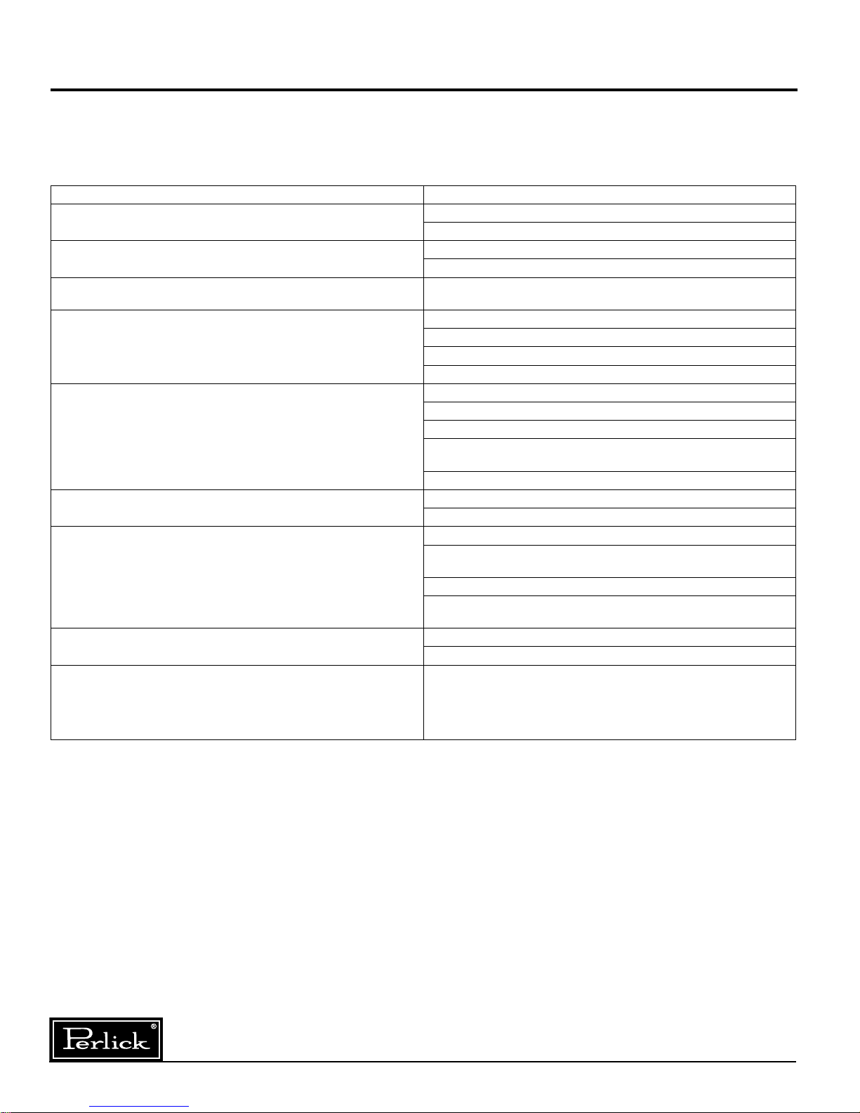
Troubleshooting
If the unit appears to be malfunctioning, read
through the OPERATION section first, then check
the guide below to identify and resolve the problem.
Electrocution hazard! Never attempt to repair or
perform maintenance on the unit until the main
electrical power has been disconnected.
PROBLEM RESOLUTION
No interior light
Light stays on when the door is closed
Noisy during operation
The refrigerated cabinet isn't running
The refrigeration compartment is warmer than usual
The refrigerated compartment is cooler than usual
The refrigerations runs for long periods of time
Condensation forms inside the refrigerated compartments
Condensation forms on the outside of the unit
Is the bulb loose?
Is the bulb burned out?
Manual ON/OFF light switch is turned on.
Is the door switch making contact with the plunger?
Certain sounds are normal. Soft sounds from the compressor, fan
motor and valves will be heard.
Is there electrical power to the unit?
Is the building circuit breaker or fuse on?
Is the control set properly?
Is the condenser area clean?
Is the control set properly?
Is the light staying on?
Is the condenser area clean and free of obstruction?
Has the door been open for a long time or more frequently door
opening occurred?
Are internal louvers and fan guard openings obstructed?
Is the control set properly?
Is the door closing and sealing properly?
Is the condenser area clean and free of obstruction?
Has the door been open for a long time or more frequently door
opening occurred?
Has warm product just been placed in the unit?
On hot days and in warm room temperatures, the system will
run longer.
This is normal during high humidity and frequent door openings.
Are the doors closing and sealing properly?
During periods of high humidity, some condensation might appear
on the outside surface. The condensation will disappear when the
humidity drops. Meanwhile, be sure doors are closing and sealing
properly. If condensation persists, contact your Perlick Factory
Authorized service center.
DANGER
To Obtain Product Information
• Contact your selling dealer.
• Inquire on the web at
www.perlick.com.
• Call 800-558-5529 for factory assistance for information, planning, installation or product information.
• Write Perlick Corporation, Customer Service Department, 8300 W. Good Hope Road, Milwaukee,
Wisconsin 53223.
• E-mail us at warrantyserv@perlick.com.
To Obtain Product Service, Replacement Parts or
Accessories:
Use only genuine Perlick replacement parts and
Perlick is committed to continuous improvement. Therefore, we reserve the right to change specifications without prior notice.
Form No. Z2288
Rev. 05.21.10
accessories. Genuine Perlick parts and accessories
are designed to work correctly with Perlick products
and offer superior service life. The use of non-Perlick
parts can damage the unit and may void the warranty.
Check the model and serial number of the unit located
on the label attached to the inside top of the cabinet.
Call a Perlick Factory Authorized service center. For
the location of the nearest Service Center, contact
your dealer, or inquire via the web at www.perlick.
com, or write to: Perlick Corporation, Customer
Service Department, 8300 W. Good Hope Road,
Milwaukee, Wisconsin 53223, call 800-558-5592,
or e-mail us at: warrantyserv@perlick.com.
8
Page 9
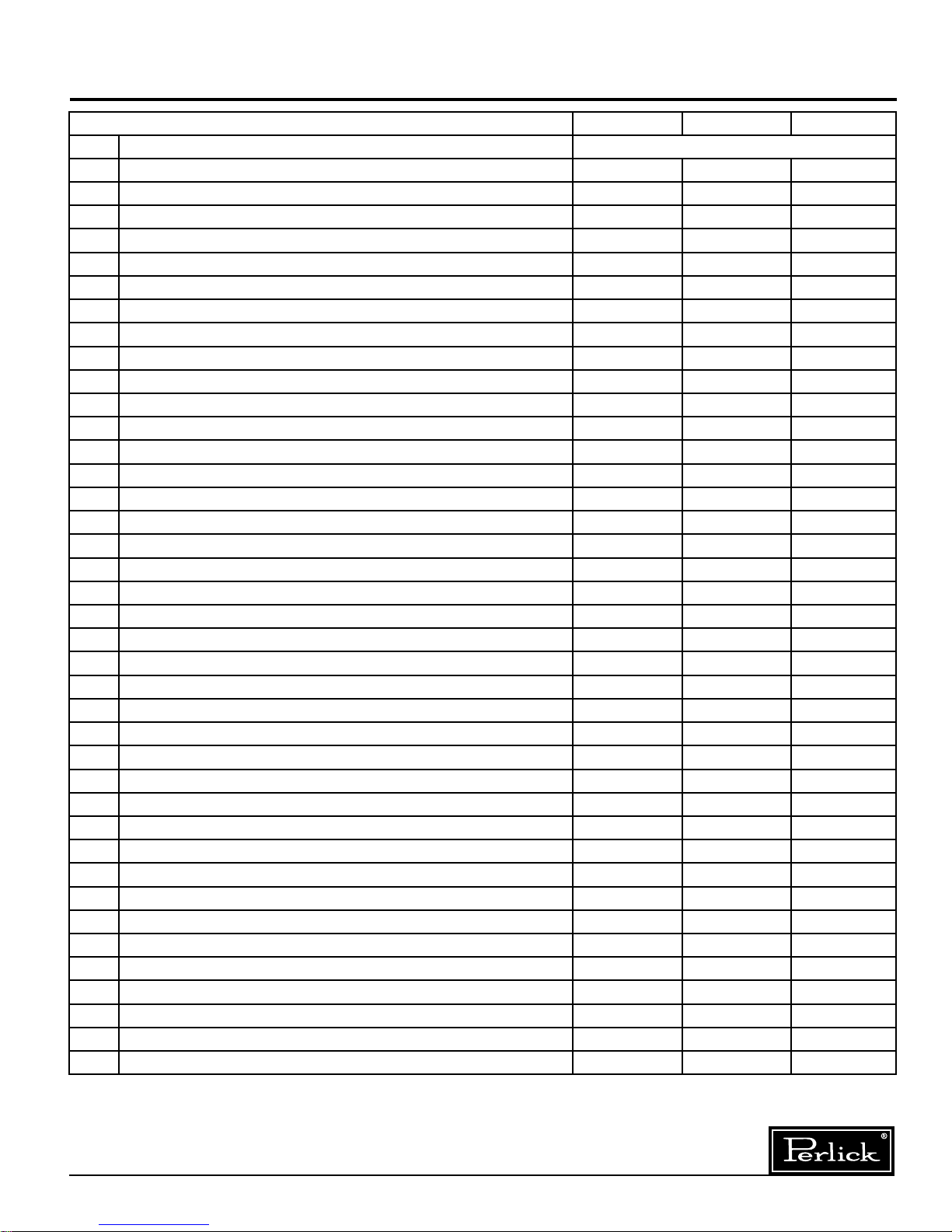
Replacement Parts
MODEL NOS. HC24RS HC24FS HC24WS
Item Description Part Numbers
1 Light switch, Rocker 63303 63303 63303
2 Door Switch, Plungers 63711 63711 63711
3 Light Assembly 63716 63716 63716
4 Light Bulb - Replacement 63716-1 63716-1 63716-1
5 Condenser/Evaporator Fan 65253 65253 65253
6 Evaporator Fan Guard 65254 65254 65254
7 Temperature Control 61282 61282 61282
8 Power Cord 65470 65470 65470
9 Wire Harness, Machine Compartment 65758 N/A 65785
10 Wire Harness, Evaporator Compartment 65759 65475 65759
11 Wire Harness, Evaporator Fan Motor N/A 65271 N/A
12 Wire Harness, 6 Hour Defrost N/A 61959 N/A
13 Wire Harness, Relay N/A 65476 N/A
14 Wire Harness, Light to Door Switch N/A 65934 N/A
15 Defrost Terminator N/A 57676 N/A
16 Solid State Controller N/A 57466 N/A
17 Time Delay Relay N/A 63794 N/A
18 Switch Monetary N/A C31659 N/A
19 Compressor w/Electricals 63778 63779 63778
20 Drier 63719 63719 63719
21 Fin Coil, Evaporator 65251 65251 65251
22 Fin Coil, Condenser 65252 65252 65252
23 L&S Line Assembly 65407 65407 65407
24 Hot Gas Solenoid Valve (Complete) N/A 63717 N/A
25 Replacement Door (Configured) RD-HC24 RD-HC24 RD-HC24
26 Gasket, Door 66237-7 66237-7 66237-7
27 Plunger Bracket for Door Switch 63948-1 63948-1 63948-1
28 Hinge Kit, Left Hand 67052L 67052L 67052L
29 Hinge Kit, Right Hand 67052R 67052R 67052R
30 Lock Kit, Left Hand 67054L 67054L 67054L
31 Lock Kit, Right Hand 67054R 67054R 67054R
32 Lock, Polished Brass (Lock Only) 67109PB 67109PB 67109PB
33 Handle, Door, Long SS 65305-1 65305-1 65305-1
34 Handle, Door, Short SS 65305-2 65305-2 65305-2
35 Handle, Door, Classic 6" Pull C31409-1 C31409-1 C31409-1
36 Handle, Door, Pull Tab 65609-3 65609-3 65609-3
37 Replacement Door Overlay (Configured) RO-CC RO-CC RO-CC
38 Replacement Shelving (Configured) RS-24 RS-24 RS-24
39 Leveling Leg 63728 63728 63728
Perlick is committed to continuous improvement. Therefore, we reserve the right to change specifications without prior notice.
9
Form No. Z2288
Rev. 05.21.10
Page 10

Wiring Diagrams
CONDENSER
FAN MOTOR
COMPRESSOR
DOOR
SWITCH
EVAPORATOR
FAN MOTOR
TEMPERATURE
CONTROL
LIGHT
SWITCH
BLUE
BLUE
RED
RED
BLACK
BLACK
21
20
22
23
BLACK
BLACK
WHITE
WHITE
WHITE
WHITE
CLOSE
@ 25° F
OPEN
@ 40° F
ON DELAY
RELAY
RELAY
S.S. TIMER
WHITE
WHITE
WHITE
WHITE
NORM. CLOSED
HOT GASS DEFROST
SOLENOID
CONDN
FAN
A2 (RED)
BLACK
BLACK
B (POWER)
TO CONDENSING
UNIT
PLUG-IN-CORD
BLUE
LIGHT
SWITCH
TEMPERATURE
CONTROL
DOOR
SWITCH
S.S.S.T MOMENTARY
CONTACT DEFROST SWITCH
W/INDICATOR LIGHT
RELAY
1
12
B W A1
A1
A
B2
B1
T11
T12
T13
T15 T14
2
3
3
4456
2
DEFROST
TEMP. LIMIT
SWITCH
INTERNAL
CONNECTIONS
BLACK
3
RED
DEFROST CYCLE:
1) AFTER 220 MINUTES:
-A2 OPENS.
-B1 CLOSES.
-HOT GAS VALVE OPENS.
-ON DELAY RELAY CONTACT CLOSES
TO 2 IN 3 MINUTES.
-THERMOSTATE IS BYPASSED.
-COMPRESSOR RESTARTS AFTER 3
MINUTES FOR HOT GAS DEFROST.
2) LIMIT SWITCH OPENS AT 40° F:
-COMPRESSOR OFF.
-HOT GAS REMAINS ENERGIZED.
3) AFRT 20 MINUTES:
-B1 OPENS.
-HOT GAS VALVE IS DE-ENERGIZED.
-A2 CLOSES.
-COMPRESSOR STARTS THROUGH
TEMPERATURE CONTROL.
HC24RS and HC24WS
Form No. Z2288
Rev. 05.21.10
Perlick is committed to continuous improvement. Therefore, we reserve the right to change specifications without prior notice.
HC24FS
10
Page 11

NOTES:
Perlick is committed to continuous improvement. Therefore, we reserve the right to change specifications without prior notice.
11
Form No. Z2288
Rev. 05.21.10
Page 12

8300 West Good Hope Road • Milwaukee, WI 53223 • Phone 414-353-7060 • Fax 414-353-7069
Perlick is committed to continuous improvement. Therefore, we reserve the right to change specifications without prior notice.
Toll Free 800-558-5592 • E-Mail: Perlick@Perlick.com • www.Perlick.com
Form No. Z2288
Rev. 05.21.10
 Loading...