

Page 1

PERLICK
SELF-CONTAINED ICE MAKER
MODEL: H50IM
PRODUCT MANUAL
Page 2

IMPORTANT
1. This booklet is an integral and essential part of the product and should be
handed over to the user. Read the warnings cont ained in this booklet carefully
as they give important indications regarding the safety of the installation,
use and maintenance. Please preserve this booklet for any further
consultation that may be necessary .
2. This Ice Maker should be destined only to the use for which it has been
expressly conceived. Any other use should be considered improper and
therefore dangerous. The manufacturer cannot be held responsible for
eventual damage caused by improper , incorrect and unreasonable use.
CONTENTS PAGE
I. GENERAL INFORMA TION ------------------------------------------------------------------------- 3
1. CONSTRUCTION---------------------------------------------------------------------------------- 3
II. INST ALLA TION AND OPERA TING INSTRUCTIONS---------------------------------------- 4
1. CHECKS BEFORE INSTALLATION ---------------------------------------------------------- 4
2. LOCATION ------------------------------------------------------------------------------------------ 5
3. ELECTRICAL CONNECTIONS ---------------------------------------------------------------- 5
4. SET UP------------------------------------------------------------------------------------------------ 6
5. WATER SUPPLY AND DRAIN CONNECTIONS ------------------------------------------- 8
6. INSTALLERS FINAL CHECKLIST ----------------------------------------------------------- 9
7. STARTUP--------------------------------------------------------------------------------------------- 9
8. PREPARING THE ICE MAKER FOR LONG STORAGE ------------------------------- 10
III. MAINTENANCE AND CLEANING INSTRUCTIONS---------------------------------------- 11
1. CLEANING AND SANITIZING INSTRUCTIONS ------------------------------------------ 11
[a] CLEANING SOLUTION ---------------------------------------------------------------------- 11
[b] CLEANING PROCEDURE ---------------------------------------------------------------- 12
[c] SANITIZING SOLUTION --------------------------------------------------------------------- 13
[d] SANITIZNG PROCEDURE ----------------------------------------------------------------13
2. MAINTENANCE -----------------------------------------------------------------------------------17
IV. WARRANTY------------------------------------------------------------------------------------------- 18
2
Page 3
I. GENERAL INFORMA TION
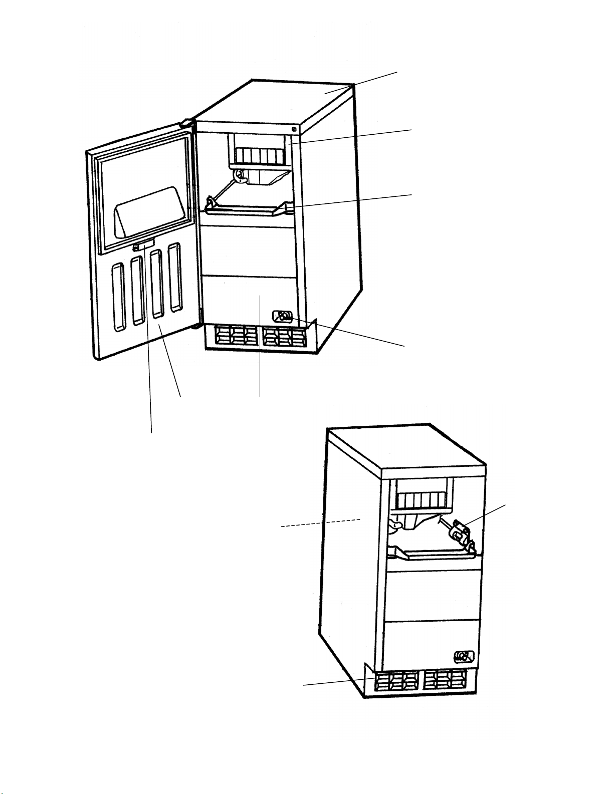
1. CONSTRUCTION
Top Panel
Ice Making
Mechanism
Slope
Control Switch
Magnet Catch
Door Removed for
Clarity of Inner
Components
Front PanelDoor
Bin Control
Thermostat
Scoop Holder
Louver
3
Page 4
II. INSTALLATION AND OPERATING INSTRUCTIONS
1. CHECKS BEFORE INST ALLA TION
* Visually inspect the exterior of the shipping container, and any severe damage noted
should be reported to the carrier.
W ARNING
Remove shipping tape(s) and packing as follows. If any are left in the Ice Maker,
it will not work properly .
IMPORTANT
1. Remove shipping tape holding the Door .
2. Ensure all components, fasteners and thumbscrews are securely in place.
* Remove the package containing accessories. Remove shipping tape holding the Separator
to the Ice Making Mechanism.
* Check that refrigerant lines do not rub or touch lines or other surfaces.
.
* Check that the compressor is snug on all mounting pads.
* Make sure that the voltage supplied to the Ice Maker is 115-120 Volts, 60hz, single
phase AC.
4
Page 5
2. LOCATION
W ARNING
Normal operating ambient temperature should be within 45°F (7°C) to 100°F
(38°C); Normal operating water temperature should be within 45°F (7°C) to
95°F (35°C). Operation of the Ice Maker, for extended periods, outside of
these normal temperature ranges may affect production capacity.
For best operating results:
* The Ice Maker should not be located next to ovens, grills or other high heat producing
equipment.
* The location should provide a firm foundation for the equipment. Level the Ice Maker from
side to side and front to rear.
* For outdoor installation, avoid locating the Ice Maker where moisture can continuously
drip on cabinet
* To prevent damage to the water supply line, drain the Ice Maker when air temperature is
below freezing, See section 8.
* This Ice Maker requires no clearance at either side. But allow enough space at rear for
water supply and drain connections and at least 15" (approx. 38 cm) clearance at front.
3. ELECTRICAL CONNECTIONS
W ARNING
THIS APPLIANCE MUST BE GROUNDED.
This Ice Maker requires a ground that meets the national and local electrical
code requirements. To prevent possible severe electrical shock injury to
individuals or extensive damage to equipment, install a proper ground wire to
this Ice Maker. Remove the plug from the mains socket before any maintenance,
repairs or cleaning is undertaken.
* This Ice Maker must be plugged into the separated power receptacle which has enough
capacity. The maximum allowable voltage variation should not exceed ± 10 percent of the
nameplate rating. See the Nameplate.
* If electrical service to the outlet is not adequate, an electrical permit and services of a
licensed electrician are required.
5
Page 6
4. SET UP
1) Unpack the Ice Maker, and remove all shipping cartons, tapes and packing BEFORE
operating the unit. Be careful not to damage the exterior panels when handling the
Ice Maker.
2) Position the Ice Maker in a selected site. Clean the interior with soap and water and rinse
thoroughly.
3) Level the Ice Maker in both the left-to-right and the front-to-rear directions.
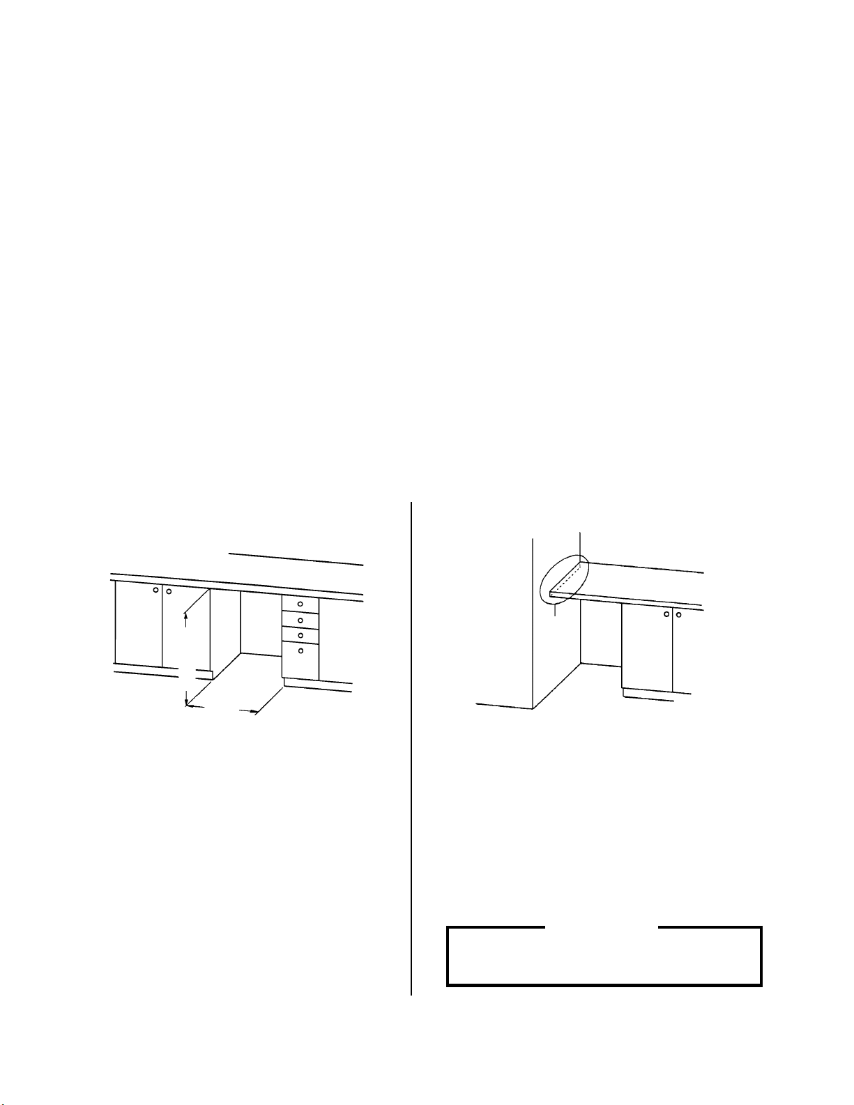
BUILT-IN INST ALLATION
[a] CHECKING INST ALLA TION SITE
Ensure 15" (381mm) wide space for building in the Ice Maker.
1) T o build in between two units:
Min. 34"
15"
Fig. 1
2) To build in between a unit and a wall or a
tall unit:
Secure
Fig. 2
Fix the counter on the wall with a bracket or
the like. Ensure 15" (381mm) wide, min. 34"
(864mm) high space for the Ice Maker.
IMPORTANT
Do not let the counter directly weigh
down the Ice Maker.
6
Page 7

3) To build in between a unit and an open
space:
Min. 34"
15"
Cabinet
Fig. 3
4 7/8"
Use a cabinet or the like to support the counter
before building in the Ice Maker.
4) To build into an L-shaped kitchen:
Min. 23"
Oven
Ice Maker
Fig. 4
[b] BUILDING IN THE ICE MAKER
Fig. 5
Do not build in the Ice Maker at a corner where
the Door will hit other equipment such as an
oven handle or where the Ice Maker cannot
be pulled out for service.
1) Make water supply and drain connections.
2) Plug in the Ice Maker.
3) Build in the Ice Maker:
Level the Ice Maker left-to-right and front-to-rear
Slowly push the lower part of the Ice Maker into place. Beware of adjacent equipment.
IMPORTANT
While building in the Ice Maker, do not damage the water supply and drain
connections and the Power Cord.
7
Page 8

5. WATER SUPPLY AND DRAIN CONNECTIONS
W ARNING
To prevent damage to the freezer mechanism, do not operate this Ice Maker
when the water supply is OFF, or if the pressure is below 10 PSIG (0.7 bar),
the recommended water pressure. Stop the Ice Maker until proper water
pressure is resumed.
* Att ach the brass fitting included in the accessory bag as shown in Fig. 5. The brass fitting
size is a 1/2" FPT and must be connected only to a potable water supply .
* A water supply line shut-off valve and drain valve must be installed.
* Water supply pressure should be a minimum of 10 PSIG (0.7 bar) and a maximum of 1 13
PSIG (7.5 bar). If the pressure exceeds 113 PSIG (7.5 bar), use a pressure reducing
valve.
* Drain outlet hose is 5/8" (16mm) ID and internally connected with 2/3" (17mm) OD drain
outlet.
* For gravity drain installation, drain must be 1/4" fall per foot (2 cm fall per meter) on horizontal
runs to get good flow.
* Keep a more than 2 vertical inch
(5 vertical cm) air gap between
the drain pipe end and the sink.
Ice Maker
Water Supply Inlet
3/4" BSP Threads
* The drain pipe must be so laid as to prevent
a backflow into the Storage Bin.
* For condensate pump installation for exiting
drain, refer to condensate pump instruction
manual.
Attach brass fitting to
Water Supply Inlet.
Fitting size is a 1/2" FPT
Shut-off V alve
* A plumbing permit and services of a licensed
plumber may be required in some areas.
* This Ice Maker should be installed in
accordance with applicable national, state
and local regulations.
Bin Drain Outlet
Hose 5/8" ID
1/4" fall per foot
Drain V alve
8
Fig. 6
T o approved floor drain
Page 9

6. INSTALLER FINAL CHECK LIST
1) Is the Ice Maker level?
2) Is the Ice Maker in a site where the ambient temperature is within 45°F (7°C) to 100°F
(38°C) and the water temperature within 45°F (7°C) to 95°F (35°C) all year around?
3) Have all shipping tape(s), string and packing been removed from the Ice Maker?
4) Are all component s, fasteners and thumbscrews securely in place?
5) Have all electrical and piping connections been made?
6) Has the power supply voltage been tested or checked against the nameplate rating?
Has a proper earth been installed to the Ice Maker?
7) Are the Water Supply Line Shut-off V alve and Drain V alve installed? Has the water supply
pressure been checked to ensure a minimum of 10 PSIG (0.7 bar) and a maximum of
1 13 PSIG (7.5 bar)?
8) Have the Compressor hold-down bolts and all refrigerant lines been checked against
vibration and possible failure?
9) Has the user been given the Instruction Manual and instructed on how to operate the
Ice Maker and the importance of periodic maintenance recommended?
10) Has the user been given the name and telephone number of the Authorized Service
Agency?
7. START UP
* Check that shipping tape(s), string and packing are removed before starting the Ice Maker.
1) Clean inside the Storage Bin and Door.
2) Open the Water Supply Line Shut-off Valve and plug in the Ice Maker.
3) Move the Control Switch to the “ICE" position.
* The freezing cycle will start automatically.
9
Page 10

8. PREPARING THE ICEMAKER FOR LONG STORAGE
W ARNING
Drain the Ice Maker to prevent damage to the water supply line at subfreezing
temperatures, using air or carbon dioxide. Shut off the Ice Maker until proper
air temperature is resumed.
1) Close the Water Supply Line Shut-of f Valve, and open the Drain Valve.
2) Move the Control Switch to the “OFF" position.
3) Blow out the water supply line and the internal water circuit.
Note: This procedure is necessary to protect the Ice Maker from freezing up at subfreezing
temperature.
4) Unplug the Ice Maker.
5) Remove all ice from the Storage Bin, and clean the Bin.
6) Close the Drain V alve.
Icemaker
Shut-off V alve
Drain V alve
Air or CO2
10
Fig. 7
Page 11

III. Cleaning and Maintenance
1. Ensure all components, fasteners and thumbscrews are securely in place
after any maintenance or cleaning is done to the equipment.
2. Wash your hands before removing ice. Use the scoop provided to remove
ice.
3. Keep the scoop clean. Clean it by using a neutral cleaner at least once a
day, and rinse thoroughly.
4. Close the bin door after removing ice to prevent entrance of dirt, dust or
insects into the bin.
5. Clean the bin liner at least once a month by using a neutral cleaner. Rinse
thoroughly after cleaning.
6. The storage bin is for ice use only. Do not store anything else in the bin.
7. Keep the area around the Ice Maker clean. Dirt, dust or insects in the
Ice Maker could cause electrical damage to the equipment or harm to
individuals.
IMPORTANT
1. Cleaning and Sanitizing Instructions
WARNING
1. PERLICK recommends cleaning this unit at least once a year. More
frequent cleaning, however, may be required in some existing water
conditions.
2. To prevent injury to individuals and damage to the Ice Maker, do not use
ammonia type cleaners.
3. Always wear liquid-proof gloves to prevent the cleaning and sanitizing
solutions from coming into contact with skin.
[a] Cleaning Solution
Dilute 5 fl. oz. (148 ml) of Perlick recommended cleaner “Scale Away" or “LIME-A-WAY"
(Economics Laboratory, Inc.) with 1 gallon (3.8 l) of warm water.
(No more than 32% phosphoric acid)
IMPORTANT
For safety and maximum effectiveness, use the solution immediately after
dilution.
11
Page 12

[b] Cleaning Procedure
The cleaning process will remove lime deposits from the water system.
1) Remove all ice from the evaporator and the storage bin.
Note: To remove cubes on the evaporator, move the control switch to the “OFF" position
and move it back to the “ICE" position after 3 minutes. The defrost cycle starts and
the cubes will be removed from the evaporator.
2) Move the control switch to the “OFF" position. Close the water supply line shut-off valve.
Water Tank
3) Disconnect the suction tube by compressing
both plastic tabs to unlock the joint in the
Suction Tube
direction of the black arrows and pulling the
tube clear.
Joint Drain
4) Spread out the tabs on both sides of the water
tank to unlock it, then pull it out toward you.
Drain the tank.
Unlock Unlock
5) After draining, slide in the water tank along the
Bracket
rails at the bottom of the right and left brackets
until it clicks into place.
Lock Lock
Rail Rail
6) Refit the suction tube onto the water tank inlet
by pushing the joint to lock it securely in the
direction of the arrows. A loose fitting may
cause a water leak.
7) Slowly pour the cleaning solution into the water tank.
8) Move the control switch to the “WASH" position.
9) After circulating the cleaning solution for about 30 minutes, move the control switch to the
“OFF" position.
12
Page 13

10) Remove the water tank, drain it, and replace it as described in 3) through 6).
11) Open the water supply line shut-off valve.
12) Move the control switch to the “WASH" position to circulate clean water for about
5 minutes.
13) Move the control switch to the “OFF" position, then remove the water tank, drain it, and
replace it as described in 3) through 6).
14) Repeat 12) and 13) three more times to rinse thoroughly.
[c] Sanitizing Solution
Dilute 0.5 fl. oz. (14.8 ml or 1 tbs) of 5.25% sodium hypochlorite solution (chlorine bleach)
with 1 gallon (3.8 l) of warm water. Using a chlorine test strip or other method, confirm that
you have a concentration of about 200 ppm.
IMPORTANT
For safety and maximum effectiveness, use the solution immediately after
dilution.
[d] Sanitizing Procedure
The sanitizing process will sanitize the Ice Maker.
1) Move the control switch to the “OFF" position.
2) Open the bin door and remove ice from the storage bin.
3) Remove the slope by bending its center carefully and releasing it from the two slope
shafts. Remove the slope from the storage bin.
4) Thoroughly clean and sanitize the storage bin,
slope, scoop and any parts normally
accessible from the storage bin.
5) Remove each separator by lifting it to the
horizontal position and pushing it hard
inward. Remove all separators in the same
way and clean and sanitize them.
Separator
13
Page 14

6) Disconnect the suction tube by
compressing both plastic tabs to unlock
the joint in the direction of the black arrows
and pulling the tube clear to drain the tank.
7) Spread out the tabs on both sides to unlock
the water tank, and pull it out toward you.
Soak the water tank in the sanitizing
solution for 10 minutes.
Water Tank
Suction Tube
Joint Drain
Unlock Unlock
8) Lift off the ice chute from the front frame
pipe and then from the rear frame pipe.
Soak the ice chute in the sanitizing
solution for 10 minutes.
9) Pull the discharge tube from the spray
assembly. Remove the assembly by
pulling it toward you.
10) Remove the two caps. Soak the caps and
the spray assembly in the sanitizing
solution for 10 minutes. If the nozzles are
clogged, clean them with a wire or a
suitable brush.
Frame Pipe
Discharge
Tube
Ice Chute
Spray
Assembly
Cap
11) Refit the two caps in their correct
positions. Make sure the reducing pipe is
in place in the center.
Reducing Pipe
14
Page 15

12) Slide in the spray assembly along the rails on
the right and left brackets. Refit the discharge
tube securely on the spray assembly. A loose
fitting may cause a water leak.
13) Position and lock the ice chute onto the front
and rear frame pipes by pushing the chute
down until it clicks onto both pipes.
Frame Pipe
Bracket
Rail Rail
14) Slide in the water tank along the rails at the
bottom of the right and left brackets until it
clicks into place.
15) Refit the suction tube onto the water tank inlet
by pushing the joint to lock it securely in the
direction of the arrows. A loose fitting may
cause a water leak.
16) Hook each separator onto the rail, and pull it
hard toward you until it locks in place with a
click. Refit all the separators in the same way.
Bracket
Lock Lock
Rail Rail
17) Refit the slope in its correct position.
18) Close the water supply line shut-off valve.
19) Discard the sanitizing solution.
15
Page 16

20) Mix a new batch of the sanitizing solution and slowly pour it into the water tank.
21) Move the control switch to the “WASH" position.
22) After circulating the sanitizing solution for about 15 minutes, move the control switch to
the “OFF" position.
Water Tank
23) Disconnect the suction tube by compressing
both plastic tabs to unlock the joint in the
Suction Tube
direction of the black arrows and pulling the
tube clear.
Joint Drain
24) Spread out the tabs on both sides of the water
tank to unlock it, then pull it out toward you.
Unlock Unlock
Drain the tank.
25) After draining, slide in the water tank along
the rails at the bottom of the right and left
brackets until it clicks into place.
26) Refit the suction tube onto the water tank inlet
by pushing the joint to lock it securely in the
direction of the arrows. A loose fitting may
cause a water leak.
27) Repeat 20) through 26) one time.
28) Open the water supply line shut-off valve.
Bracket
Lock Lock
Rail Rail
16
Page 17

29) Move the control switch to the “WASH" position to circulate clean water for about
5 minutes.
30) Move the control switch to the “OFF" position, then remove the water tank, drain it, and
replace it as described in 23) through 26).
31) Repeat 29) and 30) two more times to rinse thoroughly.
32) Move the control switch to the “ICE" position, and start the automatic icemaking process.
2. Maintenance
IMPORTANT
This icemaker must be maintained individually, referring to the instruction
manual and labels provided with the icemaker.
1) Exterior
To keep the exterior clean, wipe occasionally with a clean and soft cloth. Use a damp cloth
containing a neutral cleaner to wipe off all oil or dirt build-up.
2) Condenser
Check the condenser once a year, and clean if required by using a brush or vacuum cleaner.
More frequent cleaning may be required depending on the location of the icemaker.
17
Page 18

PERLICK H50IM ICE MAKER LIMITED WARRANTY
ENTIRE PRODUCT- Full One Year Warranty:
For one year from the date of original installation, Perlick Corporation’s warranty covers all parts and
labor to repair or replace any part of the product, which proves to be defective in material and
workmanship.
TERMS:
The Perlick Warranty applies to products installed in the fifty United States, the District of Columbia or
the ten provinces of Canada.
All service provided by Perlick Corporation under the above warranty must be performed by
authorized Perlick service representatives, unless otherwise specified by Perlick.
Service will be provided in the home during normal business hours.
This warranty applies only to products installed for normal residential use, it does not include
adjusting the controls, or cleaning the condenser.
This warranty is extended only to the original purchaser of the Perlick product.
The above warranty does not apply if:
• Failure of product was due to transportation
• Product was: improperly installed, misused, abused, operating with low voltage, wiring not
conforming electrical codes, improperly maintained or modified.
• The original Bill of Sale, delivery date or serial number cannot be verified.
• Defective parts are not returned for inspection if so required by the Perlick Corporation.
To receive parts and or service and the name of the nearest Perlick authorized service
representative, contact your Perlick dealer, distributor or Perlick Corporation’s Technical Service
Department; 8300 West Good Hope Road, Milwaukee Wisconsin, 53223; call 800 558-5592,
E-mail us at warrantyserv@perlick.com , or visit our web: www.bringperlickhome.com
This limited warranty is in lieu of any other warranty, expressed or implied, including, but not limited to
any implied warranty of merchantability or fitness for a particular purpose; provided however, that to
the extent required by law, implied warranties are included but do not extend beyond the duration of
the express warranty first set above. Perlick’s sole liability and your exclusive remedy under this
warranty are set forth in the initial paragraph above. Perlick Corporation shall have no liability
whatsoever for any incidental, consequential or special damages arising from the sale, use or
installation of the product or from any other causes whatsoever, whether based on warranty
(expressed or implied) or otherwise based on contract, tort or any other theory of liability.
Some states do not allow limitations on how long an implied warranty lasts or the exclusion or
limitation of incidental or consequential damages, so the above limitations may not apply to you. This
warranty gives you specific legal rights, and you may also have other rights, which vary, from state to
state.
8300 W. Good Hope Rd. Milwaukee, WI 53223 Phone: (414) 353-7060 Fax: (414) 353-7069 bringperlickhome.com
Perlick is committed to continuous improvement. Therefor, we reserve the right to change specifications without warning.
18
 Loading...