

Page 1
Installation
& Operation Manual
Glass Frosters
FR Series
FR48 SS shown
C
US
Form No. Z2296
Rev. 01.16.2015
Page 2
Glass Frosters Installation & Operation Manual
JOB
AREA
ITEM NO.
MODEL NO.
FR24 SERIES
FR36 SERIES
FR48 SERIES
FR60 SERIES
C
FR24 shown
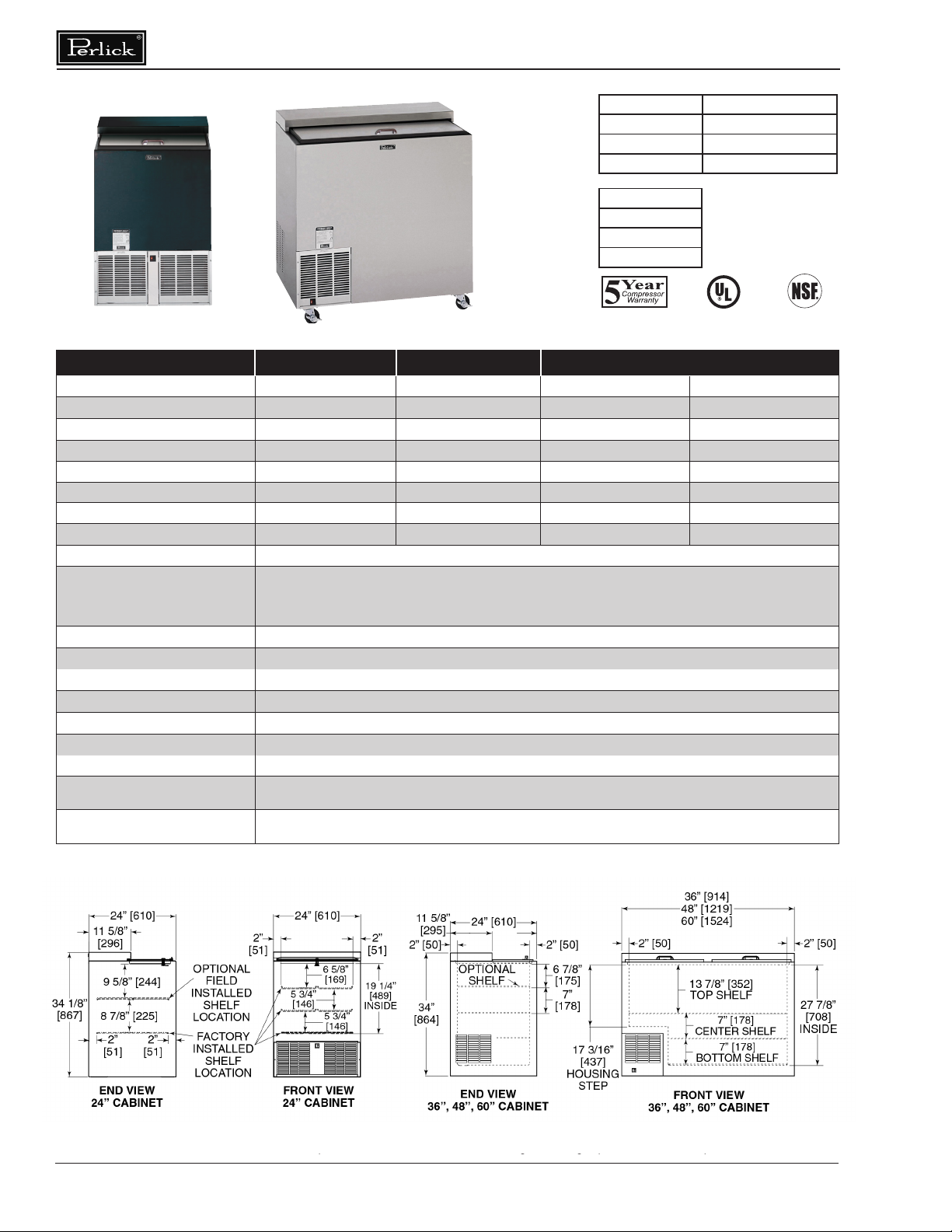
MODEL NUMBERS FR24 FR36 FR48 FR60
LENGTH (mm) 24” (610) 36” (915) 48” (1219) 60” (1524)
INTERIOR CU. FT. (m3) 3.75 (0.10) 7.83 (0.22) 11.68 (0.33) 15.53 (0.44)
PLATE CAPACITY † 135 Plates 215 Plates 300 Plates 400 Plates
GLASS CAPACITY (w/ 2 optional shelves) 90 Glasses 142 Glasses 214 Glasses 286 Glasses
WITH OPTIONAL THIRD SHELF N/A 172 Glasses 273 Glasses 363 Glasses
CONDENSING UNIT H.P. 1/3 1/3 1/3 1/3
AMPS 5.8 6.8 6.2 7.1
SHIPPING WEIGHT Lbs. (kg.) 190 (86) 245 (111) 265 (120) 300 (136)
INTERIOR All models have stainless steel walls and oor.
Choice of black, stainless steel and all stainless.
EXTERIOR
DOORS (Sliding) Stainless steel top and bottom pans. Die cast handles.
ELECTRICAL 115V, 60Hz, 1 Phase. Furnished with 6 foot rubber plug-in cord (115V model only). Also available in 230V, 50Hz, 1 Phase AC.
PLUMBING None required. Moisture drains to self-evaporating pan in machinery compartment.
INSULATION 2 inch foamed-in-place polyurethane insulation.
TEMPERATURE RANGE Adjustable from -10ºF to +10ºF.
REFRIGERATION R134a expansion valve system with hermetric condensing unit. Pulls out for service and cleaning.
VENTILATION 2’ model is front vented, all other models require 2” clearance from wall on either left end or back of cabinet for proper air ow.
DEFROST SYSTEM
OPTIONAL ACCESSORIES
Black Option: Front and ends are black vinyl coated steel, back and bottom are galvanized.
Stainless Steel Option: Front and ends are stainless steel, back and bottom are galvanized.
All Stainless Option: Front, ends, back and bottom are all stainless steel.
Solid-state, push-button defrost system, manually initiated at end of each day, automatically terminates after six hours.
Evaporator automatically defrosts every 4 hours for approximately 20 minutes (time/temperature terminated).
• Additional set of nesting shelves w/brackets • Set of 4 casters w/ brakes • Interior light
• Set of 4 adjustable legs • 2’, 3’, 4’ and 5’ Bottle rail (eld installed) • Roller basket shelving
FR36SS shown
US
† Capacity calculations based on use of 3” dia. glass and 9 1/2” dia. x 1/2” thick plate.
Perlick is committed to continuous improvement. Therefore, we reserve the right to change specications without prior notice.
Printed in USA 2
Page 3
Glass Frosters Installation & Operation Manual
DANGER
WARNING
CAUTION
TABLE OF CONTENTS
Cabinet Specications ............................................................................................................................. 2
Installing
- Uncrating and Inspection...................................................................................................................... 4
- Plumbing .............................................................................................................................................. 4
- Electrical ............................................................................................................................................... 4
- Adjusting Partitions ............................................................................................................................... 4
- Installing Casters and Legs .................................................................................................................. 4
- Placing the Cabinet .............................................................................................................................. 4
- Sealing to the Floor .............................................................................................................................. 4
Temperature Control ................................................................................................................................5
Cleaning the Cabinet ............................................................................................................................... 6
Wiring Diagrams ...................................................................................................................................... 7
Replacement Parts ............................................................................................................................... 8/9
GENERAL INFORMATION
Introduction
This manual has been prepared to assist you
in the installation of your Bottle Cooler and to
acquaint you with its operation and maintenance.
We dedicate considerable time to ensure that our
products provide the highest level of customer
satisfaction. If service is required, call Perlick at
1-800-777-7267 or your dealer who can provide
you with a list of qualied service agents. For
your own protection, never return merchandise
for credit without our approval.
We thank you for selecting a Perlick product
and assure you of our continuing interest in your
satisfaction.
SAFETY
PLEASE READ all instructions completely
before attempting to install or operate the unit.
Take particular note of the DANGER, WARNING
an CAUTION information in the manual. The
information is important for the safe and efcient
installation, operation and care of your Perlick unit.
Indicates a hazard that WILL
result in serious injury or
death if precautions are not followed.
Warranty
To register your product, visit our web site at
www.perlick.com. Click on “Commercial”, then
“Service”. Click on the link “Warranty Registration
Form”. You must complete and submit this form
or the installation date will revert back to the ship
date.
Please record the purchase date and the dealer’s
name, address and telephone number below.
Model Number: ________________________
Serial Number: _________________________
Purchase Date: _______________________
Dealer Name & Address __________________
______________________________________
______________________________________
Phone Number__________________________
Indicates a hazard MAY
cause serious injury or
death if precautions are not followed.
Indicates a hazard where
minor injury or product
damage may occur if precautions are not
followed.
Printed in USA 3
IMPORTANT!
Read and understand all information in this manual before attempting the installation.
All plumbing and electrical work must be performed by a qualied technician and
conform to all applicable state and local codes.
Perlick is committed to continuous improvement. Therefore, we reserve the right to change specications without prior notice.
Page 4

Glass Frosters Installation & Operation Manual
CAUTION
CAUTION
PREPARING THE CABINET - GLASS FROSTERS
Uncrating and Inspection
Remove all crating material. Carefully inspect
cabinet for hidden damage. If damage is
discovered, le your claim immediately with the
transport company. Perlick is not responsible for
damage in transit.
Plumbing
No plumbing connections are required.
Condensate from the cooling coil automatically
evaporated through a condensate pan located in
the condensing unit section.
Electrical
The cabinet must be connected to a separately
fused power source (see Electrical Specication
Plate afxed to unit) in accordance with National
and Local electrical codes.
Do not attempt to operate
the equipment on any
other power source than that listed on the
Electrical Specication Plate.
Placing the Cabinet
To assure maximum performance, fresh air must
be allowed to circulate through the machinery
compartment. It is important to allow at least
two inched of clearance at the back or left end
of the cabinet. Do not place anything in front of
the cabinet that would obstruct air ow at these
grilles. Do not place the unit in an unventilated
small room.
Removing the factory
installed back clearance
spacers without providing proper left side grill
clearance for compressor air ow will void the
warranty.
Cabinet should be leveled.
For sanitation purposed, it may be necessary to
seal the base of the cabinet to the oor. This can
be accomplished by laying a bead of silicone
sealant along the base of the cabinet as shown
by the gure below (gure 1).
Installing Shelves (when provided)
The front and rear horizontal shelf brackets have
been factory installed for a 2 shelf kit glass froster.
Installing Casters or Legs (optional)
Attach casters or legs to the cabinet bottom in
holes provided. Use the supplied 1/4” - 20 hex
head self-tapping machine screws. If unit is tipped
on its back for an extended period of time, wait
24 hours after unit is uprighted to plug the unit in.
Cabinet
Bead Silicon
Sealer (RTV)
Floor
Figure 1. Sealing Cabinet to Floor
Perlick is committed to continuous improvement. Therefore, we reserve the right to change specications without prior notice.
Printed in USA 4
Page 5

Glass Frosters Installation & Operation Manual
HOW TO OPERATE - GLASS FROSTERS
Defrost System
This system consists of a six-hour, as well as
a four hour defrost cycle. The six hour defrost
cycle is manually activated and automatically
terminated, while the four hour cycle is completely
automatic.
The Six Hour Solid-State Defrost Timer
This timer shuts off the power to the condensing
unit, door frame heater, evaporator heater, and the
automatic four hour defrost timer, while it supplies
power to the evaporator fan.
To activate the six hour defrost system, depress
the defrost switch located on the front grill of the
cabinet. An amber light will illuminate and the
defrost cycle will begin. When the defrost cycle
ends, the light goes off and the cabinet resumes
normal operation. To manually cancel the defrost
cycle, momentarily turn off the electricity to the
machine.
The Four Hour Defrost Timer
This timer ensures that frost will not buildup on
the evaporator coil. Every four hours it shuts
down the condensing unit and evaporator fan and
supplies power to the defrost element clamped to
the bottom of the evaporator. The defrost cycle
lasts for approximately 20 minutes.
Temperature Control
An adjustable temperature control is located inside
the Bottle Cooler on the evaporator fan panel
assembly. It is factory set at approximately 38˚F
for standard refrigeration and approximately 30˚F
for low temperature models. Make adjustments as
detailed below to attain the desired temperature.
NOTE: A temperature setting that is too low will
not allow enough condensing unit “off” time to
maintain a frost-free coil.
■ Colder Temperatures: Turn the adjusting
screw clockwise (to the right)
■ Warmer Temperatures: Turn the adjusting
screw counterclockwise (to the left).
■ Temperature Control “OFF”: Turn the
adjusting screw completely counterclockwise
to the “O” position until a “click” is noted.
The condenser fan motor turns off and on with
compressor. The evaporator fan motor runs
continuously, except during the 20 minute period
of the four-hour defrost.
During normal operation it is recommended that
the doors are not left open to prevent excessive
frost buildup on the coil.
Perlick is committed to continuous improvement. Therefore, we reserve the right to change specications without prior notice.
Printed in USA 5
Page 6

Glass Frosters Installation & Operation Manual
CLEANING INSTRUCTIONS - FLAT TOP BOTTLE COOLERS
Cleaning the Condenser
■ The condenser (located behind the from
grille) should be inspected every 30 days,
and cleaned, if necessary. Failure to
keep the condenser clean will cause a loss
in condensing unit efciency, or compressor
failure.
Cleaning the Doors
■ Doors should be periodically removed from
the cabinet and inspected for a buildup of
foreign materials, such as syrups, beer, etc.
Buildups on the underside of the doors,
along with the cabinet breaker strips on
which they ride, will cause them to bind,
and therefore, not function as designed. If
dirty, these surfaces should be cleaned with
a mild detergent and water and then coated
with a silicone lubricating material. Aerosol
silicone sprays can be obtained locally at
most hardware or automotive stores.
To remove doors:
■ With door closed, lift it upward by its handle
and slide forward until doors clears the
cabinet top. Use the reverse procedure to
reinstall the doors.
Cleaning the Cabinets
■ Use a damp cloth with a mild detergent and
water to clean the inside and outside of the
cabinet. Dry thoroughly. Do not allow cleaning
agents or large amounts of water to go down
the drain. Use an acceptable stainless steel
polish to clean all stainless steel surfaces.
Never use steel wool or scouring pads to clean
stainless steel.
Avoiding Stainless Steel Corrosion
Corrosion can be prevented by following product
cautions, cleaning instructions and avoiding use
of certain chemicals or objects which will cause
stainless steel corrosion.
STAINLESS STEEL ENEMY
■ Steel wool or steel scouring pads
■ Cherry/Orange/Olive juice
■ Chlorine Bleach
■ Sharp Objects
Perlick is committed to continuous improvement. Therefore, we reserve the right to change specications without prior notice.
Printed in USA 6
Page 7

Glass Frosters Installation & Operation Manual
WIRING DIAGRAM - GLASS FROSTERS
Perlick is committed to continuous improvement. Therefore, we reserve the right to change specications without prior notice.
Printed in USA 7
Page 8

Glass Frosters Installation & Operation Manual
REPLACEMENT PARTS - GLASS FROSTERS
Perlick is committed to continuous improvement. Therefore, we reserve the right to change specications without prior notice.
Printed in USA 8
Page 9

Glass Frosters Installation & Operation Manual
REPLACEMENT PARTS - GLASS FROSTERS
MODEL NOS. FR24 FR36 FR48 FR60
Item Description Part Numbers
1 Complete condensing unit C22646A C22646A C22646A C22646A
2 Replacement compressor, R134a 513200003 513200003 513200003 513200003
Condensing unit fan motor assy. 515315009 515315009 515315009 515315009
Terminal Board 519100088 519100088 519100088 519100088
Overload Protector US-PB12HBX1 US-PB12HBX1 US-PB12HBX1 US-PB12HBX1
Relay US-PB12HBX1 US-PB12HBX1 US-PB12HBX1 US-PB12HBX1
Start capacitor US-PB12HBX1 US-PB12HBX1 US-PB12HBX1 US-PB12HBX1
3 Condensate pan 64537 64626-1 64626-1 64626-1
4 Expansion valve 63549 63549 63549 63549
5 Evaporator fan motor(s) C15239A C15239A C15239A C15239A
6 Evaporator fan motor bracket 65671-1 65671-1 60988-1 60988-1
7 Evaporator fan motor blade 63461 63461 63461 63461
8 Evaporator fan guard 65666 65666 65666 65666
9 Evaporator coil 64785-1EP C17511-1EP C17511-1EP C17511-2EP
10 Evaporator defrost heater C25655-1 65045-1 65045-1 61900
11 Temperature control 61282 61282 65290 65290
12 Solid state defrost timer 57466 57466 57466 57466
13 Defrost limit switch 57676 57676 57656 57676
14 Rocker switch with pilot C31659 C31659 C31659 C31659
15 Compressor side shelf N/A 64810-1 64810-1 64810-1
16 Front grille 66498-2A 65662-2A 65662-2A 65662-2A
17 Rear grille/panel 66498-1 65662-3 65662-3
18 Top assembly RT-SL2 RT-SL2 RT-SL2 RT-SL2
19 Top wiper gasket 63671-24 63671-36 63671-48 63671-60
20 Door assembly RD-SL2 RD-SL2 RD-SL2 RD-SL2
21 Vertical partition 65503 66441 66441 66441
22 Roller basket N/A 66442-1 66442-1 66442-1
23 Wide shelf N/A N/A 64811-1 64811-1
24 Narrow shelf 64809-1 64809-1 64809-1 64809-1
25 Bottom oor rack (wide) 64814-1 64814-1 64814-1 64814-1
26 Bottom oor rack (narrow) N/A N/A 64815-1 64815-1
27 Shelf bracket 65653-24 65653-36 65653-48 65653-60
28 Door handle 63931 63931 63931 63931
29 Light Bulb C15046 C15046 C15046 C15046
30 Light socket 63484 63484 63484 63484
65662-3
ITEMS NOT SHOWN
Wire harness, main 65039-1 65039-1 65038-1 65038-1
Wire harness, defrost timer to switch 61959 61959 61959 61959
Suction/liquid line with drier 65089 65089 65089 65089
Mullion assembly N/A N/A 66551 66551
Refrigerant charge (oz. R134a) 8.0 10.3 12.5 12.5
Perlick is committed to continuous improvement. Therefore, we reserve the right to change specications without prior notice.
Printed in USA 9
Page 10

Glass Frosters Installation & Operation Manual
8300 West Good Hope Road • Milwaukee, WI 53223 •
Perlick is committed to continuous improvement. Therefore, we reserve the right to change specications without prior notice.
Toll Free 800.558.5592 • Fax 414.353.7069 • www.perlick.com
Printed in USA 10
 Loading...