

Page 1
READ AND SAVE THESE INSTRUCTIONS
INSTALLATION &
OPERATING MANUAL
PN 99505
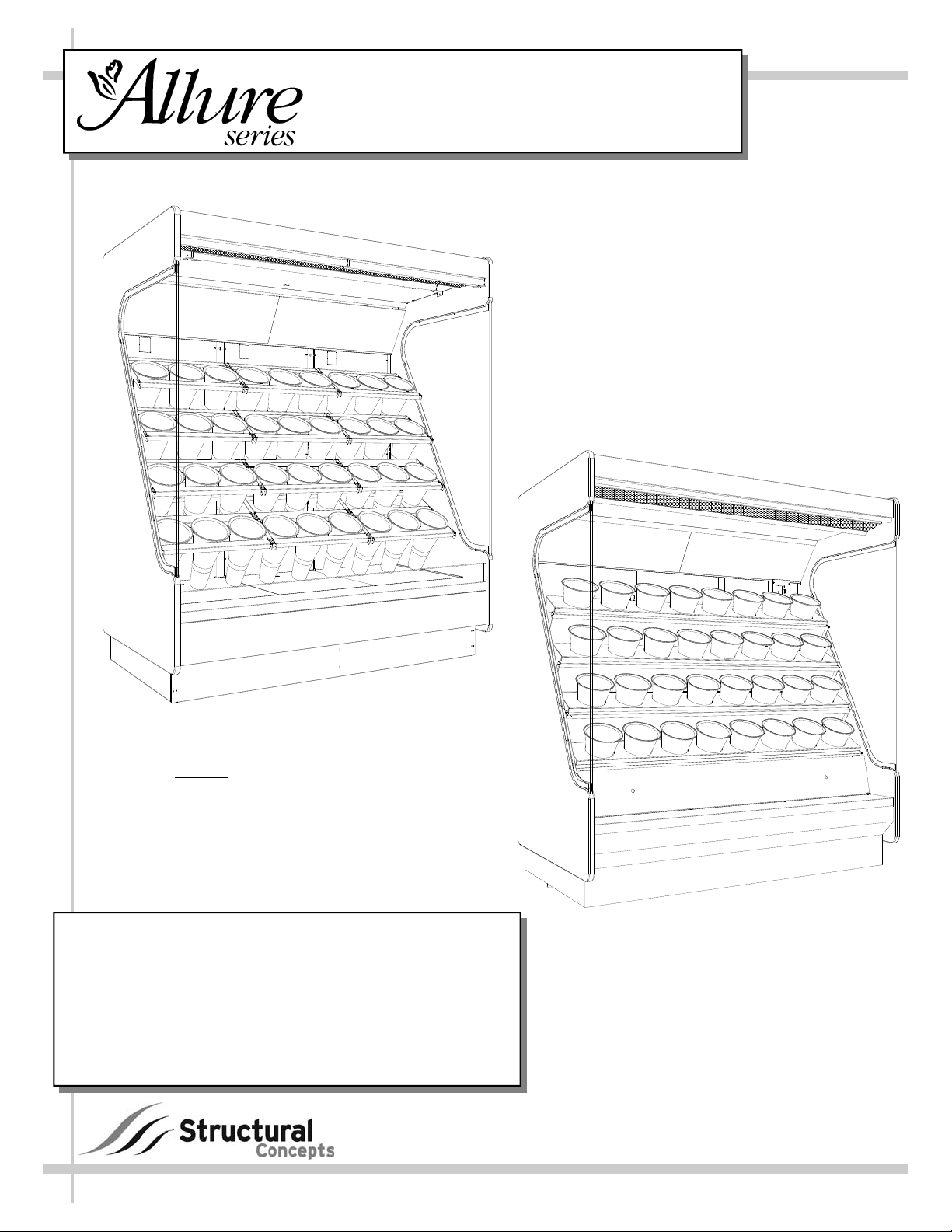
SELF-SERVICE REFRIGERATED FLORAL MERCHANDISERS with OPTIONAL WATERING SYSTEM
Standard Depth
(Non-Extended) Case
Without
Optional Watering System
Models: FR48 50”L* x 40”D x 83 3/4”H**
FR72 74”L* x 40”D x 83 3/4”H**
FR72ED 74”L* x 46 1/4”D x 83 3/4”H**
FR96 94 5/8”L* x 40”D x 83 3/4”H**
FR144ED 146”L* x 46 1/4”D x 84 3/4”H**
*With 1” End Panels.
**Height increases to 99 3/4” if unit is self-contained.
FR96ED 94 5/8”L* x 46 1/4”D x 83 3/4”H**
888 E. Porter Road · Muskegon, MI 49441 Phone: 231.798.8888 Fax: 231.798.4960 www.structuralconcepts.com
Standard Depth
(Non-Extended) Case
With Optional Watering System
I:\Oper Manuals - PUB\Allure\FR[L]_FR[L]ED_99505.pub
Rev H Date: 10.16.2009
Page 2
TABLE OF CONTENTS
OVERVIEW AND WARNINGS ……………...…………………..…….……………………………
INSTALLATION ………………………………………………………………………………………..
START-UP AND OPERATION (STANDARD SYSTEM) …………………………………………
START-UP AND OPERATION (WATERING SYSTEM) …………………………………………
MAINTENANCE FUNDAMENTALS: HONEYCOMB / EVAPORATOR COIL FANS ACCESS
MAINTENANCE FUNDAMENTALS: LIGHTS (FLUORESCENT vs. LED) …..…..…………….
MAINTENANCE FUNDAMENTALS: REFRIG. TXV VALVE / WATER SUPPLY VALVE …….
MAIN TUB DRAIN ACCESS (OPTIONAL WATERING SYSTEMS ONLY) .……………………
SERIAL LABEL LOCATION & INFORMATION LISTED / TECH INFO & SERVICE ...…..……
TROUBLESHOOTING ……..….……………………………………………….………….…………
ILLUSTRATED PARTS BREAKDOWN (WATERING SYSTEM UNITS ONLY) ..……………..
CLEANING SCHEDULE ..……………………………………………...……………………………
CAREL® TEMPERATURE CONTROLLER ……………………………………………………….
A419 CONTROLLER OPERATION ………………………………………………………………..
A419 CONTROLLER CHANGING SET POINTS …………………………………………………
A419 CONTROLLER FAULT CODES …...…………………………………………………...……
A419 TOUCHPAD LOCKING …………………………………...……………………………….....
A419 CONTROLLER TROUBLESHOOTING .…………………………………………………….
TECHNICAL SERVICE CONTACT INFORMATION & WARRANTY INFORMATION ………..
3
4-9
10
11
12
13
14
15
16
17-18
19
20
21-23
24
25
26
27
28
29
2
Page 3
OVERVIEW AND WARNINGS
OVERVIEW
• The Structural Concepts Allure self-service cases are designed to merchandise products at
41° F product temperature.
• These cases should be installed and operated according to the following instructions to
insure proper performance.
• This unit is designed for the display of products in ambient store conditions where
temperatures and humidity are maintained at a maximum of 75° F and 55% relative
humidity.
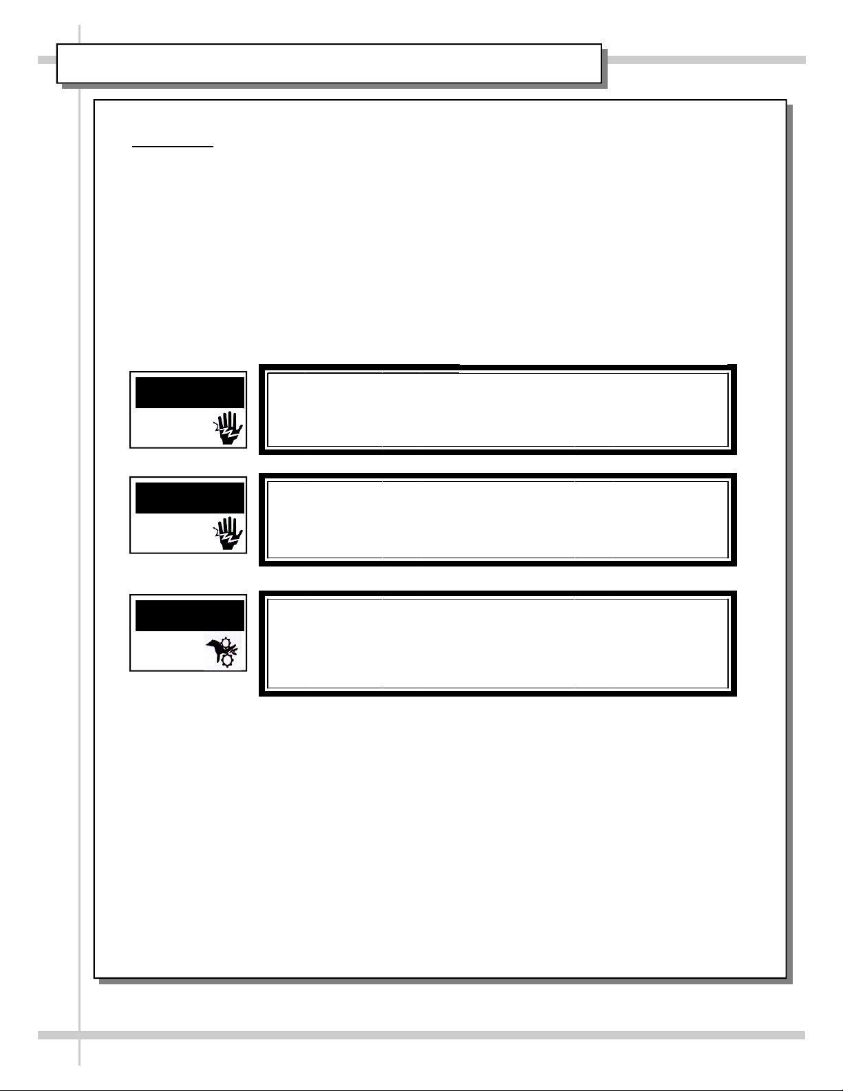
WARNING
ELECTRICAL
HAZARD
WARNING
ELECTRICAL
HAZARD
WARNING
KEEP HANDS
CLEAR
WARNING
Risk of Electric Shock.
Disconnect Power Before Servicing Unit
WARNING
More Than One Source of Electrical Supply.
Disconnect All Sources Before Servicing.
Employed with units that have separate circuits.
WARNING
Hazardous Moving Parts.
Do Not Operate unit with covers removed.
Fan blades may be exposed when deck panel is removed. Disconnect
power before removing deck panel.
3
Page 4
INSTALLATION
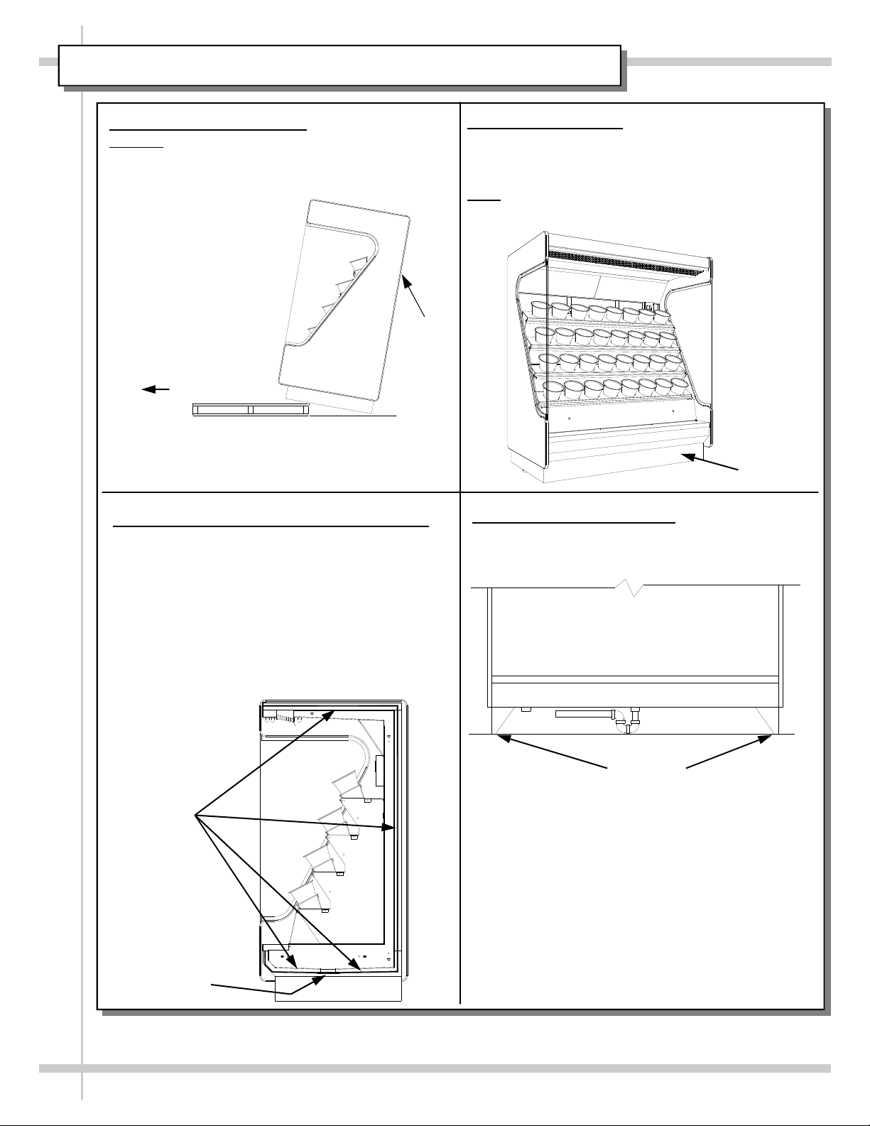
1. Remove Unit From Skid
Caution
: Case must always remain supported
or center of gravity will allow case to fall. Slide
unit to rear of skid and tip backward off skid.
Support
Slide Skid Out
Case to be repositioned with pallet truck from front or rear.
Front access requires removal of the lower panel.
Blocking may be necessary to obtain adequate height.
3. Before Securing Multiple Units Together
Lay a generous bead of butyl rubber caulk
(manufacture provided) along the edge of tub.
• See the following figure.
• Area to be caulked is shown as a dark line around tub.
• Caulking the tub prevents air from escaping through
seams between cases which cause condensation
problems as well as reduced refrigeration efficiency.
• Caulking also prevents water from seeping between
the cases to the floor.
2. Transporting Case
Remove front toe-kick and position pallet truck in
front center of case being careful to avoid
drainage and electrical fittings.
Note
: Illustration below may not reflect every
feature or option of your particular case.
Toe-Kick
4. Position and Level Units
Position Units. Level unit with shims (3” x 3” x
1/16” provided by the manufacture.
Caulk
Line
Drain
Level Units
4
Page 5
INSTALLATION, CONTINUED
4. Bolting Multiple Units Together
Bolt units together at holes indicated at right.
Access bolt holes at 5 locations
• Use SCC-provided 1/4-20 x 2.50” bolts.
• Bolt holes 1 & 2 are on tabs.
• Remove decks to access bolt holes 3 thru 5.
Diffuser panel Knockouts
1
5. Front Panel Joiner Covers
Note: A toe-kick gap cover is provided when
two cases with an end panel in-between them
are bolted together.
• Remove front toe-kicks and position cover
between toe-kicks and case.
Cover
2
3
4
Decking
5
Caulking
Above illustration may not reflect every
feature or option of your particular case.
Mirrors
Note: The next page provides
Case
Cover
Toe-Kicks
Case
Drain Connections for both
Standard Cases AND Cases
with Optional Watering
Systems.
5
Page 6
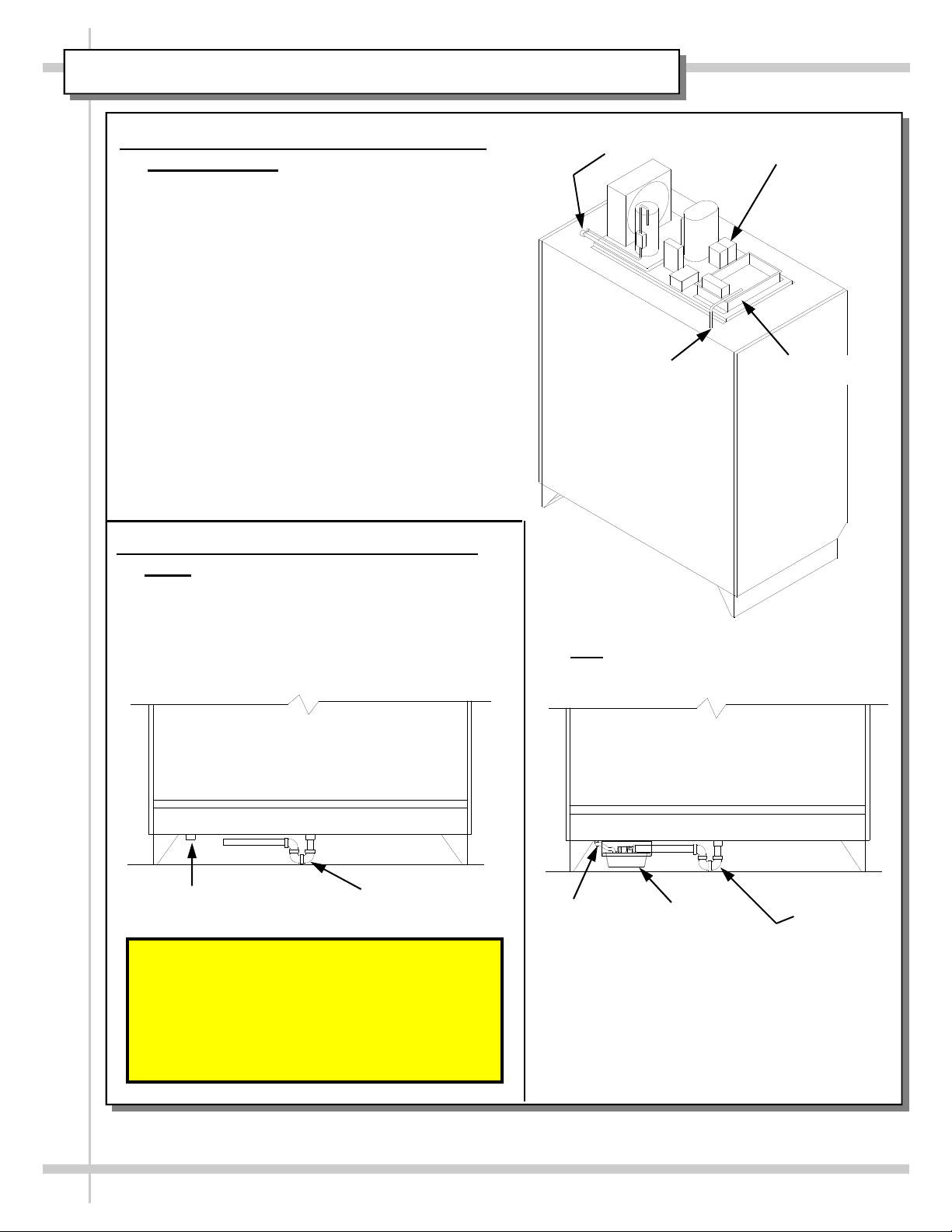
INSTALLATION, CONTINUED
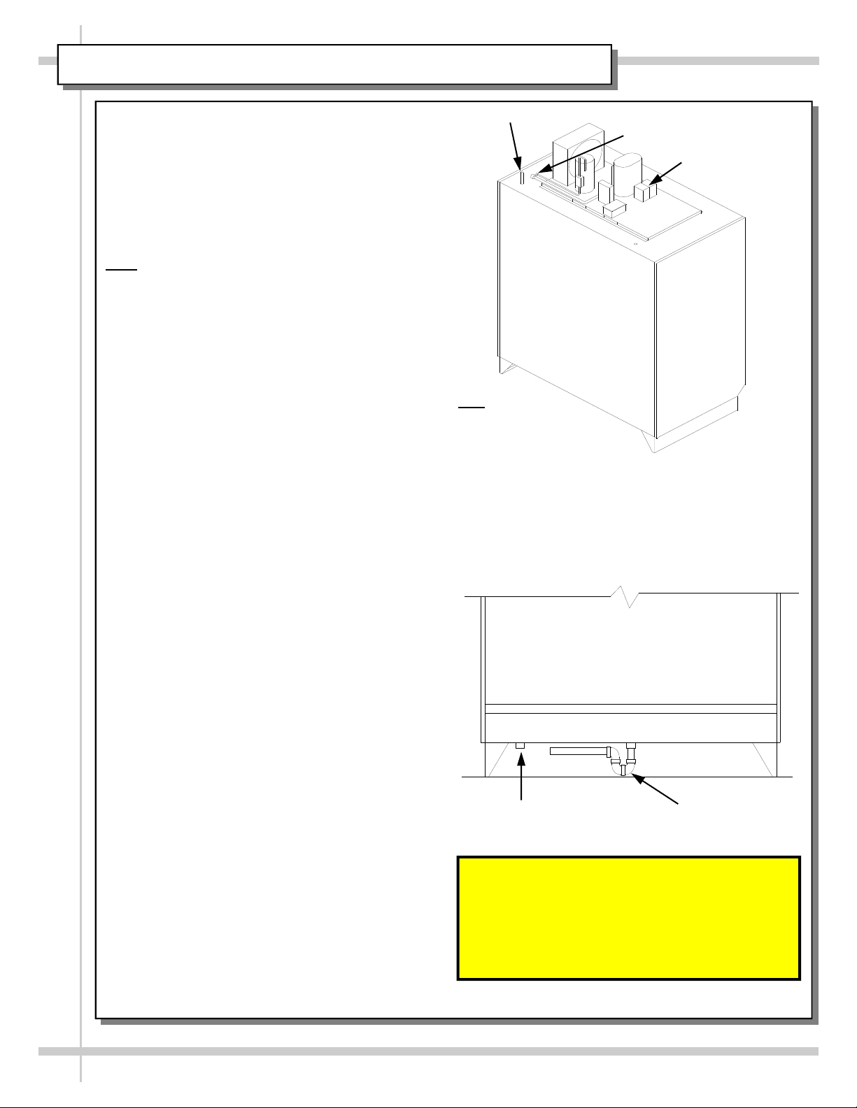
6. Drain Connections - Standard System Self Contained
Self-Contained systems:
• The electrical stub up connection is pro-
vided on the refrigeration assembly on top
of case.
• Refrigeration quick disconnect connections
are provided at case rear at top of case.
• A 1/2” flex reinforced hose is provided to
evacuate condenser water from
condensate pump pan to an evaporator
pan placed on the top of case.
• A 1 1/2” male PVC drain connection is pro-
vided for condensate drainage. It is at the
center of the base for cases FR72 & FR96.
7. Drain Connections - Watering System
Units
• A 1 1/2” male PVC drain connection is
provided for condensate at center base.
• A 2” male PVC drain connection is provided
for the troughs at the left base.
Quick Disconnects
Transfer
Hose
Note: Above (and below) illustrations may
not reflect exact case specifications.
Electrical Stub
Evaporator Pan
Troughs Drain
Condensate Drain
Important! For Proper Drain
Operation, Each Drain Is
To Be Piped Independently.
Do Not “TEE” Drains Together!
6
Transfer
Hose
FR72/96 Typical
Condensate
Pump & Pan
Condensate
Drain
Page 7
INSTALLATION, CONTINUED
8. Remote Refrigeration Case
Connections
Note: Standard single phase connections are
required and should be performed by a certified
electrician.
• Refrigeration system.
Refrigeration stub up connections are
provided on the rear side at either the
top or base of case per customer
request.
• Water System
A 3/4” female connection is provided for
the supply watering system on the rear
side at the top of case.
• Electrical system
A 120 volt electrical stub up connection
is provided on the rear side at either the
top or base of case per customer
request.
9. Adding Refrigeration Condenser
Using a forklift or other suitable lifting device,
place refrigeration unit atop case.
Note: Base of refrigeration unit is designed to
accommodate forklift forks.
Fork Locations
Water Stub Up
Quick Disconnects
Electrical Stub Up
10. Refrigeration Connections
Note: Assembly or disassembly and servic-
ing to be accomplished by licensed refrigeration contractor.
1. Connect the refrigerant quick disconnect
connections that are on the rear side at
the top of case.
2. Secure the refrigeration unit with the pro-
vide No. 10 self drilling screws after
connecting quick disconnects. Starter
holes are located at each corner of condenser base.
3. Connect the light ballast and heating element receptacle to the case plug.
4. Connect the thermostat receptacle of
compressor to case plug.
7
Page 8
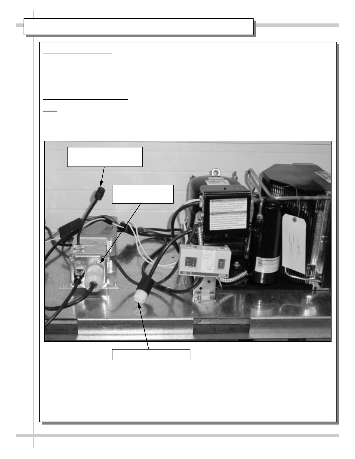
INSTALLATION, CONTINUED
11. Water Connections
Water connections are accessed from the top of the unit.
• A 3/4” female connection is provided for the supply watering system on the rear side at the top of
case.
• Check fitting, under pressure, for leakage prior to installing either front toe kick or rear grill.
12. Electrical Connection
Note: Standard single phase connections are required and are to be performed by certified electrician.
• A 220 volt electrical stub up connection is provided on the refrigeration assembly.
• Remove screws from 4X4 box provided for field hook up.
Light Ballast and Heating
Element Receptacle
Compressor Power
Receptacle
Thermostat Receptacle
8
Page 9
INSTALLATION, CONTINUED
Access and Connections
Self-Contained refrigeration with power cord.
• For your safety, equipment is furnished with
a properly grounded cord connector. Do not
attempt to defeat the grounded connector.
• Plug cord into certified electrical outlet w/ground.
Self-Contained refrigeration without power cord.
Note: Standard single phase connections required
and are to be performed by certified electrician.
• A 220 volt electrical stub up connection is provided on the refrigeration assembly.
• Remove screws from 4X4 box provided for field
hook up.
• Leads are labeled for identification.
Temperature Settings
• The case temperature Set Point is set at the
factory, as determined by the case size and
sensor probe location.
• The temperature is controlled by a thermostat.
• If a temperature setting change is required, refer
to the Temperature Controller section of this
manual for instructions on changing set point.
Remote Refrigeration Systems.
Note: Servicing to be accomplished by
refrigeration contractor.
• Refrigeration stub up connections are provided
on the rear side at either the top or base of case
per customer request.
Water System
• A 3/4” female connection is provided for supply
watering system on rear side at the top of case.
• Check fitting, under pressure, for leakage prior to
installing either front toe kick or rear grill.
Condensation Drain Connection
• The condensate drain exits the base of tub assembly.
• Removing rear grille will expose access to the
drain connections. See Drain Access in
Refrigeration & Watering Fundamentals section.
Electrical Leads
• Note: Standard single phase connections are
required and must be performed by a certified
electrician.
• 120 volt electrical stub up connections are provided on the rear side at either the top or base of
case per customer request.
Water Stub Up
Quick Disconnects
Electrical Stub Up
Note: Illustration
may not reflect
exact case
specifications.
Drain Connections
• A 1 1/2” male PVC drain connection is
provided for condensate at the center base.
• A 2” male PVC drain connection is provided
for the troughs at the left base.
Trough Drain
Condensate Drain
Important! For Proper Drain
Operation, Each Drain Is
To Be Piped Independently.
Do Not “TEE” Drains Together!
9
Page 10

START-UP AND OPERATION (STANDARD SYSTEM) - SEE PAGE 11 FOR WATERING SYSTEM
Merchandiser Start-Up
• Turn on main power circuit breaker. Coil
fans, (and in self-contained units, the
compressor motor) should turn on. From
the front of the case, remove the deck
for access to coil fans. Check to see
that the coil fans are all functioning
properly.
Check across the top of the front to see
•
if air is discharging across the entire
front of the case.
Turn lights on. All of the lights should
•
come on at the same time. First time
lighting may require a short warm up
period for the bulbs. Slightly dim or a
flickering of new bulbs is normal.
The case temperature is set at the factory,
as determined by the case size. The
temperature is controlled by a thermostat.
If a temperature setting change is required,
follow the instructions in the Temperature
Control section of this manual.
Shelf Assembly Removal
• Shelves can be removed for cleaning or
adjustments
• Remove buckets.
• Remove rear shelf and bucket
supports.
• Lift the rear shelf close-off up to
separate from brackets.
• Rotate rear shelf supports forward
and up to separate from brackets.
• Rotate front buckets supports
backward and up to separate from
brackets.
• Remove brackets. Note it may be
necessary to remove the nylon shipping bracket retainer. A pliers will be
required to accomplish this task.
Lights &
Fixtures
Light
Switch
Location
Deck Removal
For Coil Fans
Access
Honeycomb
Upper Mirror
Assembly
10
Page 11

START-UP AND OPERATION (WATERING SYSTEM) - SEE PAGE 10 FOR STANDARD SYSTEM
Merchandiser Start-Up
Note: Check trough cover for proper installation. Holes for buckets must be to the front of
the trough or the buckets will not fit properly.
• Turn on main power circuit breaker. Coil
fans, (and in self-contained units, the
compressor motor) should turn on. From
the front of the case, remove the deck for
access to coil fans. Check to see that the
coil fans are all functioning properly.
Check across top of the front to see if air is
•
discharging across the entire front of case.
Turn lights on. All lights should come on at
•
the same time. First time lighting may require a short warm-up period for the bulbs.
Light Switch
Slightly dim or flickering of new bulbs is
normal.
Fresh Flow Automatic Watering System
— Control Panel Operating Instructions —
ON/OFF POWER:
• Switch to “off” position to halt water cycles
during periodic cleaning of the Fresh Flow
system. Switch back to “on” position to
continue the automatic system operation.
15-MINUTE REFILL TIMER:
• In order to refill the trough(s) after cleaning,
touch this switch (one time) to start the
cycle. This will allow a 15-minute fill cycle
to occur. An audible alarm will sound just
prior to the cycle completion.
• To Cancel Fill Cycle, touch refill timer
twice in one second.
DIAL TIMER:
• Set timer switch for (2) 15-minute cycles
per day by pushing (2) actuator pins toward
Electrical Assembly
the center of timer switch. The visible
orange areas indicate switched-on periods.
Thermostat Control
The case temperature is set at the factory, as
determined by the case size. The temperature
is controlled by a thermostat. If a temperature
setting change is required, refer refer to the
Temperature Controller section of this manual
for instructions on changing setpoint.
Push Down/In
11
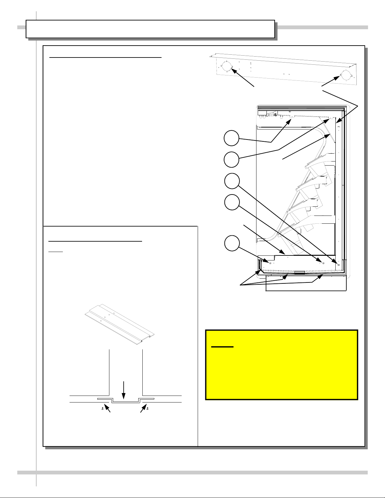
Page 12

MAINTENANCE FUNDAMENTALS: HONEYCOMB / EVAPORATOR COIL FANS ACCESS
Honeycomb Air Diffuser Removal
Caution: avoid damage to heat tape
concealed in front honeycomb retainer.
• Obtain a nonmetallic device of suitable
strength such as a ballpoint pen.
• Wedge the instrument between the honey-
comb and the top cap closure/end panel.
• Apply pressure to collapse the honeycomb
and pry downward and away from the
honeycomb retainer.
• Pull honeycomb out fully buy grasping with
fingers and pulling downward.
Honeycomb Air Diffuser Installation
• Insert honeycomb up into front channel
first.
Apply suitable pressure to collapse the
honeycomb from the back side and press
into the honeycomb retainer.
Evaporator Coil Fans Access
Servicing to be accomplished by licensed
electrical contractor.
Warning, disconnect power before
providing maintenance to unit.
• Remove decking.
• Unplug fan cords at fan shroud.
• Remove thumb screws.
• Carefully removal the fan shroud.
Heat Tape
Evap. Fans
Apply Pressure to begin
removal of Honeycomb.
Honeycomb Retainers
Deck Pans
12
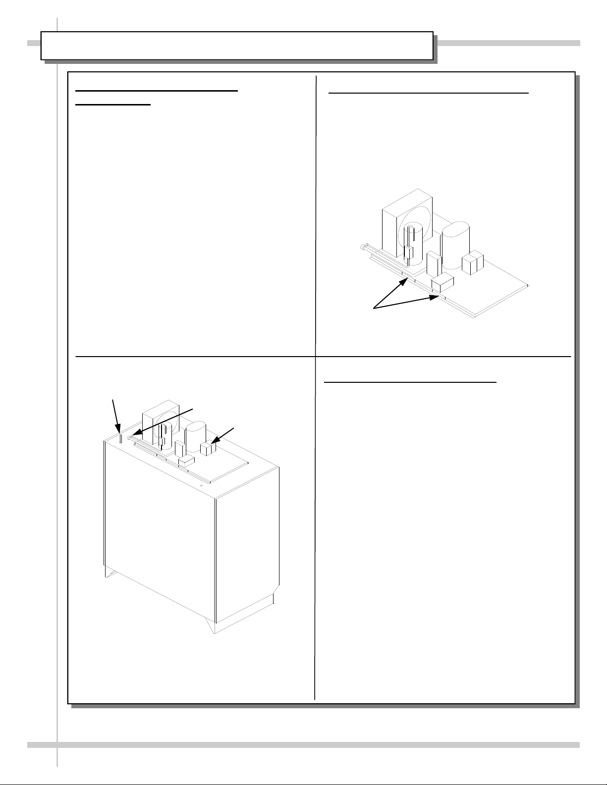
Page 13

MAINTENANCE FUNDAMENTALS: LIGHTS (FLUORESCENT vs. LED)
Florescent Lights
• Standard lighting is florescent.
• See illustration at top-right for display of
florescent lights installed in case.
• Ballast box is at top-left of case
Light Ballast Access
Servicing to be accomplished by licensed
electrical contractor.
Warning, disconnect power before providing
maintenance to unit.
• Ballast are at top of display case on customer-
left side. See illustration at mid-right.
• Remove cover to access light ballasts.
LED Light Option
• If LED lights are chosen, light ballasts will not be
present on case.
Light Ballasts
LED light removal / replacement:
• LED lights they rarely require change-out.
• Contact Structural Concepts’ Technical Service
cover removed)
Department for replacement parts.
• To remove LED light fixture, disconnect existing
LED light from its brackets & self-adhesive tape.
• Then, firmly grasp LED light while applying out-
ward pressure to brackets.
• Twist the LED away from the bracket to release.
Plug and cord positioning:
• Plug connects to LED light at raceway side.
• Before attaching LED light to case, plug must
connect to LED without cord doubling-back.
• See photos of proper vs. improper connections.
Proper plug insertion into LED light:
• Plug must be inserted into LED light properly or
the LED will not light up.
• Oval form of plug is to connect to LED light oval
form. See illustration at right.
.Bracket Retainer Removal
• To remove brackets, it may be necessary to
remove the nylon shipping bracket retainers.
• Pliers will be required to accomplish this task.
• See illustration at top-right for location of bracket
retainers.
Fluorescent
Lights
(shown with
Top of
Display
Case
Customer-Left Side
of Display Case
Plug’s Oval
Form
LED’s
Oval Form
Fluorescent
Lights
Bracket
Outward pressure to be applied
to bracket to remove LED light
13
Page 14

MAINTENANCE FUNDAMENTALS: REFRIGERATION TXV VALVE / WATER SUPPLY VALVE
Refrigeration Expansion Valve Access
• The expansion valve is accessible from the
front of the case.
• Remove decking.
• Remove inspection/access panel in the front
right corner of the unit.
• The expansion valve (TXV) is directly below
the access panel.
Water Supply Valve Access (Optional
Watering System Units Only)
• Servicing to be accomplished by licensed
electrical contractor.
• Warning, disconnect power before pro-
viding maintenance to unit.
• Water solenoid valve and manifold assembly
is behind upper right hand mirror mounted to
the diffuser panel.
• Recess the corresponding mirror and slide
behind opposite mirror.
Diffuser Panel
Valve & Manifold Assembly
14
Expansion Valve
Page 15

MAIN TUB DRAIN ACCESS (OPTIONAL WATERING SYSTEMS ON LY)
Main Tub Drain Access
1. Remove Lower Trough Close-Off (optional watering systems only); no screws are required to be
removed to remove lower trough close-off (see illustration below).
2. Remove Lower Front Access Panel (at Customer-Right of Display Case).
Refrigeration Expansion Valve Access
1
1. Remove Lower Trough Close-Off (optional watering systems only); no screws are required to be
removed to remove lower trough
close-off (see illustration below).
2. Remove Lower Front Access Panel
(at Customer-Left of Display Case).
Illustration at right has
right end panel
removed to allow view
of inner case.
1. Lower Trough
Close-Off
TXV Valve Front Access Panel
(Removed To Reveal TXV)
Drain Front Access Panel
(Shown Intact: Must Be
Removed To Access
Floor Drain)
(Accessible By Removing Lower
Front Access Channel)
Floor Drain
15
Page 16

SERIAL LABEL LOCATION & INFORMATION LISTED / TECH INFO & SERVICE
Serial Label Location & Information Listed / Technical Information & Service
• Serial labels are located near the electrical access on your case.
• Serial labels contain electrical, temperature & refrigeration information, as well as regulatory
standards to which the case conforms.
• For additional technical information and service, see the TECHNICAL SERVICE page in this
manual for instructions on contacting Structural Concepts’ Technical Service Department.
• See images below for samples of both refrigerated and non-refrigerated serial labels.
S
A
M
P
L
E
O
N
L
Y
Y
L
N
O
E
L
P
M
A
S
----- Sample Serial Label For Refrigerated Case -----
Y
L
N
O
E
PL
M
SA
----- Sample Serial Label For Non-Refrigerated Case -----
888 E. Porter Road · Muskegon, MI 49441 Phone: 231.798.8888 Fax: 231.798.4960 www.structuralconcepts.com
16
Page 17

TROUBLESHOOTING
Product is drying out
Water on the floor
Water runs continuously.
Buckets do not fit in trough
Trough does not maintain
Water level.
Excessive fan noise
Check the relative humidity in the store.
Check that all of the hoses are connected.
Check that the drain trap is free of debris.
Check that the trough filter is free of debris.
Check that the overflow tube is free of debris.
Check that the time clock is set correctly. See page 5 for setting
timer.
Check that water supply solenoid is operating correctly.
Check trough cover for proper installation. Holes should be
offset to front of case
Check that the overflow tube is installed correctly.
Check that the case is aligned, level and plumb.
Check that nothing is obstructing the blade rotation.
System is not operating
Fans not working
Case lights not working
Condensing unit not operating
(self contained unit).
Check that the fan shroud is properly secured.
Check that the utility power is on.
Check that the MAIN power switch is on.
Check the circuit breaker box for tripped circuits.
Check that the power is on.
Check that the fans are plugged in at the fan shroud.
Determine if there is ice build up blocking the fan.
Check bulbs for proper installation and connection.
Check for burned out bulbs.
Clean dirt and dust from the bulbs to prevent flickering.
Check that the power is turned on.
Check the reset button on top of the pressure control.
17
Page 18

TROUBLESHOOTING, CONTINUED
Not holding temperature
Check that the coil fans are working.
Check that the inlet air is not disrupted or blocked by product.
If a large amount of warm product was added to the case, it will
take time for the temperature to adjust.
Check the coil for ice build up.
Check that the condenser coil is clean (self contained unit).
Check that the case is not in the sun or near a heat or air-
conditioning vent.
Case temperature will rise during defrost mode but will return
to normal.
Is case located near front doors.
Thermostat setting is too high. Refer to the Temperature
Controller section in this manual.
18
Page 19

ILLUSTRATED PARTS BREAKDOWN (WATERING SYSTEM UNITS ONLY)
Fresh Flow® Automatic Water System
(Patent Pending)
Timed Switch
Main Power Switch
Transformer
Solenoid Valve
Timer Clock
Water Inlet
Trough Assemblies
Overflow tube
Trough Filter
Internal Fill Elbow
External drain Elbow Assy.
External Fill Elbow
19
Page 20

CLEANING SCHEDULE (DAILY / WEEKLY / MONTHLY / QUARTERLY)
Cleaning D W M Task
Clean Case
Exterior
Clean Case
Interior
X
X
Q
Clean all case exterior surfaces with a household or
commercial glass cleaner and a soft cloth.
Clean the interior case deck and trough surfaces with a
warm water and mild soap solution.
Keep drains clean and free of debris which could clog the
X
drain and rob the case of needed refrigeration. Vacuum
tub under deck or flush with water if necessary.
X Remove the decks. Clean with soap and water solution.
X Remove buckets. Clean with soap & water solution.
Watering System Units Only: Remove the trough covers
X
and clean interior of covers and troughs with soap and
water.
Self-contained
units only.
Clean Condensing
Coil
X
Using air pressure if available, or an industrial strength
vacuum, clean the dust & dirt that collects on condenser
coil. (Be careful not to damage fins on coil.)
Clean Condensing Unit (Including Evaporator Pan)
Warning: Evaporator pan may be hot. Allow
Evaporator Pan to cool approximately 30-minutes
before cleaning.
1. Remove Rear Lower Panel.
2. Turn off power. Disconnect case from power source.
3. Remove Rear Grille by removing 4 screws.
4. Disconnect Evaporator Pan electrical connection from
Receptacle Box.
5. Remove Evaporator Pan mounting screws from the
Compressor Pan.
Self-contained
units only.
Clean Condensing
Unit (Including
Evaporator Pan)
X
6. After Evaporator Pan has cooled, remove from unit.
7. Thoroughly clean Evaporator Pan with hot soap and
water solution and firm bristle brush. DO NOT
submerse in water.
8. For stubborn residue, use a de-scaling solution such
as CLR®. Rinse thoroughly. DO NOT submerse in
water.
9. Use clean towel dipped in soap and water solution to
wipe down all fans, motor, refrigeration lines, cords,
knobs, sight glass, connectors and all other surfaces.
10. Wipe dry.
11. Reposition Evaporator Pan on Compressor Pan.
12. Reattach mounting screws to Evaporator Pan.
13. Reconnect Evaporator Pan electrical connections.
14. Slide back under case.
15. Replace Rear Grille.
16. Replace Rear Lower Panel.
20
Page 21

Read And Save These Instructions - Page 1 of 3
Integrated Electronic
Microprocessor Controller
Programming The Instrument
How To Modify The Setpoint
Press and hold the “SET” key for at least 1 second.
Set
Prg
mute
Set
▲
aux
def
▼
How To Modify The Defrost, Differential
Or Other Parameters
Prg
mute
Set
▲
aux
Set
▲
aux
Set
Prg
mute
Warning! Save Your Parameter Settings!
1. Press & hold “Prg” and “SET” keys together
Set
for at least 5 seconds; the display will show the
number “0”, representing the password prompt.
2. Confirm by pressing “SET” key.
3. Press ▲ or ▼ to reach the
def
category to be modified.
▼
4. Press “SET” to modify this selected parameter.
5. Increase or decrease the value using
def
the ▲ or ▼ button respectively.
▼
6. Press the “SET” key to temporarily save the new
value and return to the display of the parameter.
7. Press & hold the “Prg” key for at least 5 seconds
to save changes. This action will also mute the
audible alarm (buzzer) & deactivate the alarm relay.
Prg
mute
Set
▲
aux
Set
▲
aux
Set
Prg
mute
1. To store the new parameter values, PRESS and HOLD the “Prg” key for at least 5 seconds.
2. All modifications made to parameters will be lost if you do NOT press a button within 60 seconds. Should
this “timeout” occur, normal operational settings (prior to modifications being made) will resume.
3. If the instrument is switched off before pressing the “Prg” key, all modifications to parameters will be lost.
How To Activate Manual Defrost
def
Press and hold the “def” key for at least 5 seconds.
▼
How To Activate / Deactivate Auxiliary Output
▲
Press and hold the “aux” key for at least 1 second.
aux
How To Change Reading From
Fahrenheit (°F) To Celsius (°C)
1. Press and hold “Prg” and “SET” keys
Set
together for at least 5 seconds; display will
2. Confirm by pressing “SET” key.
4. Press “SET” to modify this selected parameter.
6. Press “SET” key to temporarily save the new
value and return to the display of the parameter.
7. Press & hold “Prg” key for at least 5 seconds to
save changes.
convert to new scale. No conversion is required.
show “0”, representing password prompt.
def
3. Press ▲ or ▼ until reaching the
parameter “/ 5”.
▼
5. Press ▲ or ▼ to change value to desired
def
setting: “0” for Celsius (°C) or “1” for
▼
Fahrenheit (°F).
Note! All values will automatically
How To Reset Any Alarms With Manual Reset
Prg
mute
▲
Press and hold the “Prg” and “aux” key for at least 1 second.
aux
Structural Concepts Corp., 888 E. Porter Rd · Muskegon, MI 49441
Ph: 231.798.8888 / Fax: 231-798-0393 / www.structuralconcepts.com
21
I:\Oper Manuals - PUB\Templates\Carel Controller\Carel Controller IR33.pub
This data derived from Carel Material: ir33 +030220441 - rel. 2.0 - 01.05.2006
Page 22

Read And Save These Instructions - Page 2 of 3
Integrated Electronic
Microprocessor Controller
User Interface - Display
Summary Table of Alarm and Signals: Display, Buzzer and Relay
reset alarms w/manual reset / reset HACCP alarms / reset temp. monitoring
Structural Concepts Corp., 888 E. Porter Rd · Muskegon, MI 49441
Ph: 231.798.8888 / Fax: 231-798-0393 / www.structuralconcepts.com
22
I:\Oper Manuals - PUB\Templates\Carel Controller\Carel Controller IR33.pub
This data derived from Carel Material: ir33 +030220441 - rel. 2.0 - 01.05.2006
Page 23

Read And Save These Instructions - Page 3 of 3
Integrated Electronic
Microprocessor Controller
Summary Table of Operating Parameters
CODE PARAMETER UOM* TYPE MINIMUM MAXIMUM DEFAULT
/5
Select Celsius (°C) or Fahrenheit (°F)
flag C 0 1
/c1 Calibration of probe 1 °C/°F C -20 20
/c2 Calibration of probe 2 °C/°F C -20 20
St Temperature set point °C/°F F r2 r1
rd Control delta °C/°F F 20 0.1
dl Interval between defrosts hours F 0 250
dt1 End defrost temperature, evaporator °C/°F F -50 200
dP1 Maximum defrost duration, evaporator min F 1 250
d6 Display on hold during defrost - C 0 2
For Case
Specific
Defaults
See Serial
Label
Located
Near
Electrical
Access
On Your
Case.
For
Additional
Technical
Information
Call
Structural
Concepts
Technical
Service
Dept. at
1(800)
433.9489
dd Dripping time after defrost min F 0 15
d/1 Display of defrost probe 1 °C/°F F - -
* Unit Of Measure
Structural Concepts Corp., 888 E. Porter Rd · Muskegon, MI 49441
Ph: 231.798.8888 / Fax: 231-798-0393 / www.structuralconcepts.com
23
I:\Oper Manuals - PUB\Templates\Carel Controller\Carel Controller IR33.pub
This data derived from Carel Material: ir33 +030220441 - rel. 2.0 - 01.05.2006
Page 24

A419 Controller Operation
The A419 Control Functions
Setpoint (SP) establishes the temperature value at which the equipment is switched on or off, depending
on the user selected mode of operation. Setpoint range is -30 to 212°F or -34 to 100°C (in 1-degree
increments).
If Setpoint mode is set to cut-in, setpoint is the temperature value at which the control closes the Normally
Open (N.O.) contacts. If Setpoint mode is set to cutout, setpoint is the temperature at which the N.O. contacts
open.
Differential (dIF) establishes the difference in temperature between the cut-in value and cutout value. The
differential is set relative to Setpoint and may be set from 1 to 30 F° or C° (in 1-degree increments).
Anti-Short Cycle Delay (ASd) establishes the minimum time that the output relay remains de-engergized be-
fore the next on-cycle. The Asd does not allow the output relay to re-energize until the programmed time de-
lay has elapsed. The delay is activated when the control is first turned on and every time an on-cycle ends.
When the delay is activated, the LCD alternately flashes the sensor temperature and ASd. The Anti-short Cy-
cle Delay range is 0 to 12 minutes (in 1-minute increments).
Sensor Failure Operation (SF) establishes how the A419 control’s output-relay operates the equipment in the
event of a sensor or sensor wiring failure. The user may select to run the equipment continuously or to shut it
down. When the control detects a sensor circuit failure, the LCD flashes SF alternately with OP (if the sensor
circuit is open), or SH (if the sensor circuit is shorted). Before indicating a failure, the control implements a
1-minute delay, which allows verification of failure condition and avoids nuisance failure indications.
Temperature Offset (OFS) establishes a set secondary Setpoint and Differential values that may be in-
voked to control an application when a circuit is closed between the binary input (BIN) and common (COM)
terminals (and BIN appears on the display). See Figure 3. Offset range is 0 to 50F° or C° (in 1- degree incre-
ments). A typical application might use a switching time clock to invoke night-setback temperature settings.
Display Symbols, Control Function, Ranges, Units, Values
* The sum of the Setpoint and Differential values must be within the Setpoint range, or the control may not function properly.
24
24
Page 25

A419 Controller Changing Set Points
Changing the A419 Control Temperature Units
Functions Ranges
Liquid Crystal Display, Touch pad,
and LED Indicator
25
Page 26

A419 Controller Fault Codes
Fault Codes Defined
26
Page 27

A419 Touchpad Locking
Jumper Designations, Jumper Positions and Control Settings
27
Page 28

A419 Controller Troubleshooting
28
Page 29

TECHNICAL SERVICE CONTACT INFORMATION & WARRANTY INFORMATION
STRUCTURAL CONCEPTS CORPORATION TECHNICAL SERVICE
PHONE NUMBER: 1.800.433.9489 or For Your Master Service Agent See
WWW.STRUCTURALCONCEPTS.COM/Contact/Master_Service_Agents.asp
WARRANTY INFORMATION
(Note: Standard Limited Warranty can be found at www.Struct ural conc ept s.com)
All sales by Structural Concepts Corporation (SCC) are subject to the following limited warranty. “Goods” refers to the product or products being sold by SCC.
Warranty Scope: Warranty is for equipment sold in the United States, Canada, Mexico and Puerto Rico. Equipment sold elsewhere may carry modifi ed warranty.
Warranty; Remedies; Limitations. SCC warrants that if any Goods are found by an authorized representative of SCC not to be of good material or workmanship within one
year of the date of shipments SCC will, at its option after inspection by an authorized representative, replace any defective Good or pay the reasonable cost of replacement
for any such defective Goods, provided that written notice of the defect is given to SCC within 30 days of the appearance of such defect. If notice is not given within such
period, any claim for breach of warranty shall be conclusively deemed to have been waived and SCC shall not be liable under this warranty. If SCC is unable to repair or
replace the defective Goods, SCC shall issue a credit to the Purchaser for all or part of the purchase price, as SCC shall determine. The replacement or payment in the
manner described above shall be the sole and exclusive remedy of Purchaser for a breach of this warranty. If any Goods are defective or fail to conform to this warranty,
SCC will furnish instructions for their disposition. No Goods shall be returned to SCC without its prior consent.
SCC’s liability for any defect in the Goods shall not exceed the purchase price of the Goods. SCC SHALL HAVE NO LIABILITY TO PURCHASE FOR CONSEQUENTIAL
DAMAGES OF ANY KIND WHATSOEVER, INCLUDING, BUT NOT LIMITED TO, PERSONAL INJURY, PROPERTY DAMAGE, LOST PROFITS, OR OTHER ECONOMIC
INJURY DUE TO ANY DEFECT IN THE GOODS OR ANY BREACH OF SCC, SCC SHALL NOT BE LIABLE TO THE PURCHASER IN TORT FOR ANY NEGLIGENT
DESIGN OR MANUFACTURE OF THE GOODS, OR FOR THE OMISSION OF ANY WARNING THEREFROM.
SCC shall have no obligation or liability under this warranty for claims arising from any other party’s (including Purchaser’s) negligence or misuse of the Goods or
environmental conditions. This warranty does not apply to any claim or damage arising for or cause by improper storage, handling, installation, maintenance, or from fire,
flood, accidents, structural defects, building settlement or movement, acts of God, or other causes beyond SCC’s control.
Except as expressly stated herein, SCC makes no warranty, express, implied, statutory or otherwise as to any parts or goods not manufactured by SCC. SCC shall warrant
such parts or Goods only (I) against such defects, (II) for such periods of time, and (III) with such remedies, as are expressly warranted by the manufacturer of such parts of
Goods. Notwithstanding the foregoing, any warranty with respect to such parts of Goods and any remedies available as a result of a breach thereof shall be subject to all of
the procedures, limitations, and exclusions set forth herein.
THE WARRANTIES HEREIN ARE IN LIEU OF ALL WARRANTIES, EXPRESS, IMPLIED, STATUTORY, OR OTHERWISE. IN PARTICULAR, SCC MAKES NO
WARRANTY OF MERCHANTABILITY OR FITNESS FOR A PARTICULAR PURPOSE.
No representative, agent or dealer of SCC has authority to modify, expand, or ext end this Warranty, to waive any of the limitations or exclusions, or to make any different or
additional warranties with respect to Goods.
Period of Limitations. No claim, suit or other proceeding may be brought by Purchaser for any breach of the foregoing warranty or this Agreement by SCC or in any way
arising out of this Agreement or relating to the Goods after one year from the date of the breach. In the interpretation of this limitation on action for a breach by SCC, it is
expressly agreed that there are no warranties of future performance of the goods that would extend that period of limitation herein contained for bringing an action.
Indemnifications. Purchaser agrees to indemnify, hold harmless, and defend SCC if so requested, from any and all liabilities, as defined herein, suffered, or incurred by SCC
as a result of, or in connection with, any act, omission, or use of the Goods by Purchaser, its employees or customers, or any breach of this Agreement by Purchaser.
Liabilities shall include all costs, claims, damages, judgments, and expenses (including reasonable attorney fees and costs).
Remedies of SCC. SCC’s rights and remedies shall be cumulative and may be exercised from time to time. In a proceeding or action relating to the breach of this Agreement
by Purchaser, Purchaser shall reimburse SCC for reasonable costs and attorney’s fees incurred by SCC. No waiver by SCC of any breach of Purchaser shall be effective
unless in writing nor operate as a waiver of any other breach of the same term thereafter. SCC shall not lose any right because it has not exercised it in the past.
Applicable Law. This Agreement is made in Michigan and shall be governed by and interpreted according to Michigan law. Any lawsuit arising out of this Agreement or the
Goods may be handled by a federal or state court whose district includes Muskegon County, Michigan, and Purchaser consents that such court shall have personal
jurisdiction over Purchaser.
Miscellaneous. If any provision of this Agreement is found to be invalid or unenforceable under any law, the provision shall be ineffective to that extent and for the duration of
the illegality, but the remaining provisions shall be unaffected. Purchaser shall not assign any of its rights nor delegate any of this obligations under this Agreement without
prior written of SCC. This Agreement shall be binding upon and inure to the benefit of SCC and Purchaser and each of their legal representatives, successors and assigns.
SCC warrants its products to be free of defects in materials and workmanship under normal use and service for a period of one (1) year from the date of delivery.
This warranty is extended only to the original purchaser for use of the Goods. It does not cover normal wear parts such as plastic tongs, tong holders, tong cables, bag
holders, or acrylic dividers.
General Conditions. All service labor and/or parts charges are subject to approval by SCC. Contact the Customer Service Department in writing or call 231-798-8888.
All claims must contain the following information: (1) model & serial code number of equipment; (2) the date and place of installation; (3) the name and address of the agency
which performed the installation; (4) the date of the equipment failure; and (5) a complete description of the equipment failure and all circumstances relating to that failure.
Once the claim has been determined to be a true warranty claim by SCC’s Customer Service Department, the following procedure will be taken: (1) replacement parts will be
sent at no charge from SCC on a freight prepaid basis; (2) reimbursement for service labor will be paid if the following conditions have been met— (a) prior approval of service agency was awarded from the Customer Service Department; and (b) an itemized statement of all labor charges incurred is received by the Customer Service Department. The cost of the service labor reimbursement will be based on straight time rates and reasonable time for the repair of the defect.
If problems occur with any compressor, notify SCC’s Customer Service Department immediately. Any attempt to repair or alter the unit without prior consent from the
Customer Service Department will render any warranty claim null and void. This warranty and protection plan does not apply to any condensing unit or any part thereof which
has been subject to accident, negligence, misuse, or abuse, or which has not been operated in accordance with the manufacturer’s recommendations or if the serial number
of the unit has been altered, defaced, or removed.
Limit of Liability. The limit of liability of SCC toward the exchange cost of the original condensing unit, F.O.B. SCC, Norton Shores, MI, of each motor-compressor assembly
replaced during the warranty shall not exceed manufacturer's current established wholesaler’s exchange price and in no case shall the labor of removing or replacing the
motor-compressor or parts thereof be the responsibility of SCC.
29
 Loading...