

Page 1
INSTALLATION AND OPERATION INSTRUCTIONS
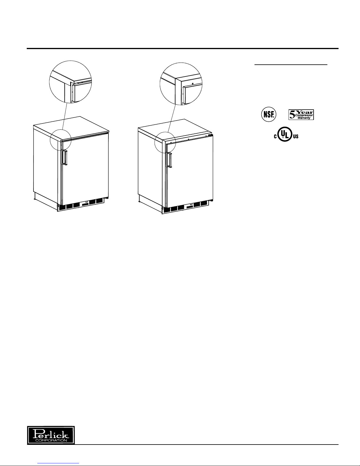
SINGLE DOOR FREEZER
MODEL NOS.
F24N
F24S
F24S F24N
IMPORTANT INFORMATION
This manual has been prepared to assist you in the
installation of your Freezer and to acquaint you with
its operation and maintenance.
We dedicate considerable time to ensure that our
products provide the highest level of customer
satisfaction. If, however service is required, call
Perlick at 1-800-777-7267 or your dealer who can
provide you with a list of qualified service agents. For
your own protection, never return merchandise for
credit without our approval.
We thank you for selecting a Perlick product
and assure you of our continuing interest in
your satisfaction.
IMPORTANT WARRANTY INFORMATION
A Warranty card is enclosed that must be completed
and mailed to the Perlick Corporation in order to
register the warranty. If the card is not returned to
Perlick, the warranty period will begin from the date
the equipment is shipped from the factory.
Table of Contents
Cabinet Specifications ..........................................2
Installing
Uncrating and Inspection................................3
Plumbing.........................................................3
Electrical..........................................................3
Installing Shelves............................................3
Installing Casters or Legs
Placing The Cabinet........................................3
Sealing the Floor.............................................3
Defrost System .....................................................4
Temperature Control .............................................4
Cleaning................................................................5
Cleaning Stainless Steel/Avoiding Corrosion .......5
Replacement Parts ............................................6/7
Wiring Diagram.....................................................8
................................
3
8300 West Good Hope Road • Milwaukee, WI 53223 • Phone 414-353-7060 • Fax 414-353-7069
Toll Free 800-558-5592 • E-Mail: Perlick@Perlick.com • www.Perlick.com
Form No. Z2255
Rev. 4.19.05
Page 2
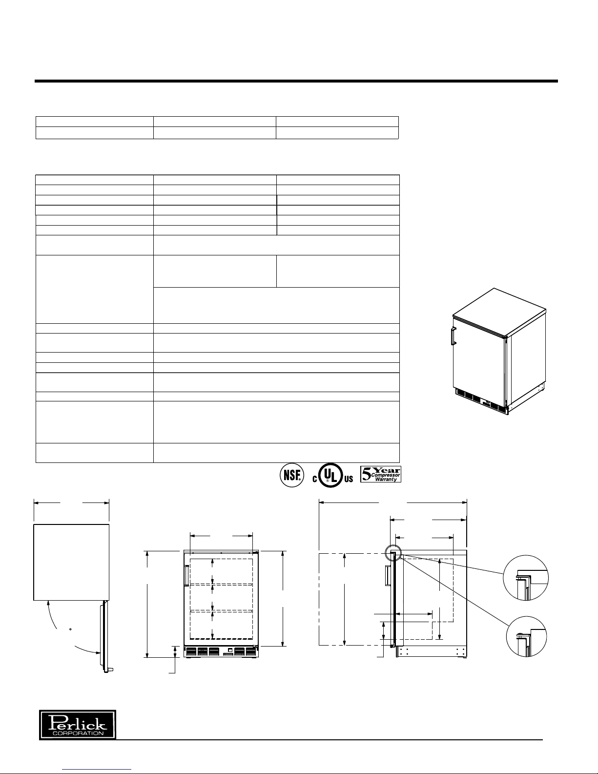
Sizes and Specifications
+
ELEC TR IC AL
VE NT ILAT IO N
Single Door Freezer
MODEL NUMBERS
BLA CK DO OR F24NB F24SB
STAINLESS STEEL DOOR F24NS F24SS
SPECIFICATIONS
LENG TH (mm )
INTERIOR Cu. FT. (m3 )
GLAS S CAPAC ITY
CO ND ESING UNIT H .P .
AM PS
SH IP W T lb s. (kg)
INTERIOR
EXTERIOR
PLUM BING
INSULATION
TEMP ERA TU RE R ANGE
RE FR IG ERATION
DE FR OST SYS TE M
OP TION AL A CCESS ORIE S
Capacity calculations based on use of 3” dia. Glasses on standard shelving.
Both Models: Inner Liner is stainless steel. Includes two adjustable vinyl coated shelves plus a bottom shelf
Back, top, and sid es are
galvanize d ste el
Both models: Fro nt is 20ga stainles s steel.
Doors are either black powder coat, 20ga C RS o r 20ga s tainless
steel. Bottom is 18ga galvanized steel with 20ga stainless
115V, 60Hz., 1 Phase. Furnish ed with 6 foot ru bber plu g-in c ord
None required. Moisture drains to self evaporating cond
in mach inery compartm en t
2 inch foamed-in-place polyurethane insulation
Adjus table from -1 0 to +10de g F (-23 to -12deg C)
R134a capillary tube type with hermetic condensing unit.
Fro nt ac cess fo r c ondenser and cleanin g
Fro nt vente d.
Solid-state, push button hot gas defrost system, manually initiated
at end of each day, automatically terminates after six hours.
Evaporator automatically defrosts every 4 hours for approximately
20 minutes (time/temperature terminated)
*Set of 4 c as ters (3 3/4 " h igh) P /N 65426
*Set of 4 a djustable legs (6" - 7 1/4" high) P /N 65 423
24" (6 10) 24" (6 10)
4.9 (0.14 ) 4.9 (0.14 )
86 Glasses 86 Glasses
1/5 HP 1/5 HP
2.0 2.0
145 (5 4) 145 (5 4)
Top a nd sides a re 20ga
sta inless steel
Back is galva nized steel
ens
grille
ate pan
23 7/8"
[610]
34 1/2"
[887]
180
DOOR SWING
3 11/16"
[92]
8 7/16" [214]
TOP VIEW FRONT VIEW
Perlick is committed to continuous improvement. Therefore, we reserve the right to change specifications without prior notice.
19 7/8"
8" [203]
8" [203]
[508]
30 9/16"
[776]
47 1/8"
[1197]
24 1/4"
29 1/4"
[743]
11 3/4"
[470]
5 9/16"
[141]
[615]
18 1/2"
[470]
25 3/4"
[654]
FINISHED
STAINLESS
TOP
NO FINISHED
TOP
END VIEW
2
Form No. Z2255
Rev. 4.19.05
Page 3
Preparing the Cabinet – Single Door Freezer
TOP VIEW
SHOWN
Uncrating and Inspection
Remove all crating material before operating.
Carefully inspect cabinet for hidden damage.
If damage is discovered, file your claim immediately
with the transport company. Perlick is not
responsible for damage in transit.
Plumbing
No plumbing connections are required. Condensate
from the cooling coil is automatically evaporated
through a condensate pan located in the
condensing unit section.
Electrical
The cabinet must be connected to a separately
fused power source (see Electrical Specification
Plate) and grounded in accordance with National
and Local Electrical Codes.
CAUTION: Do not attempt to operate the equipment
on any other power source than that listed on the
Electrical Specification Plate.
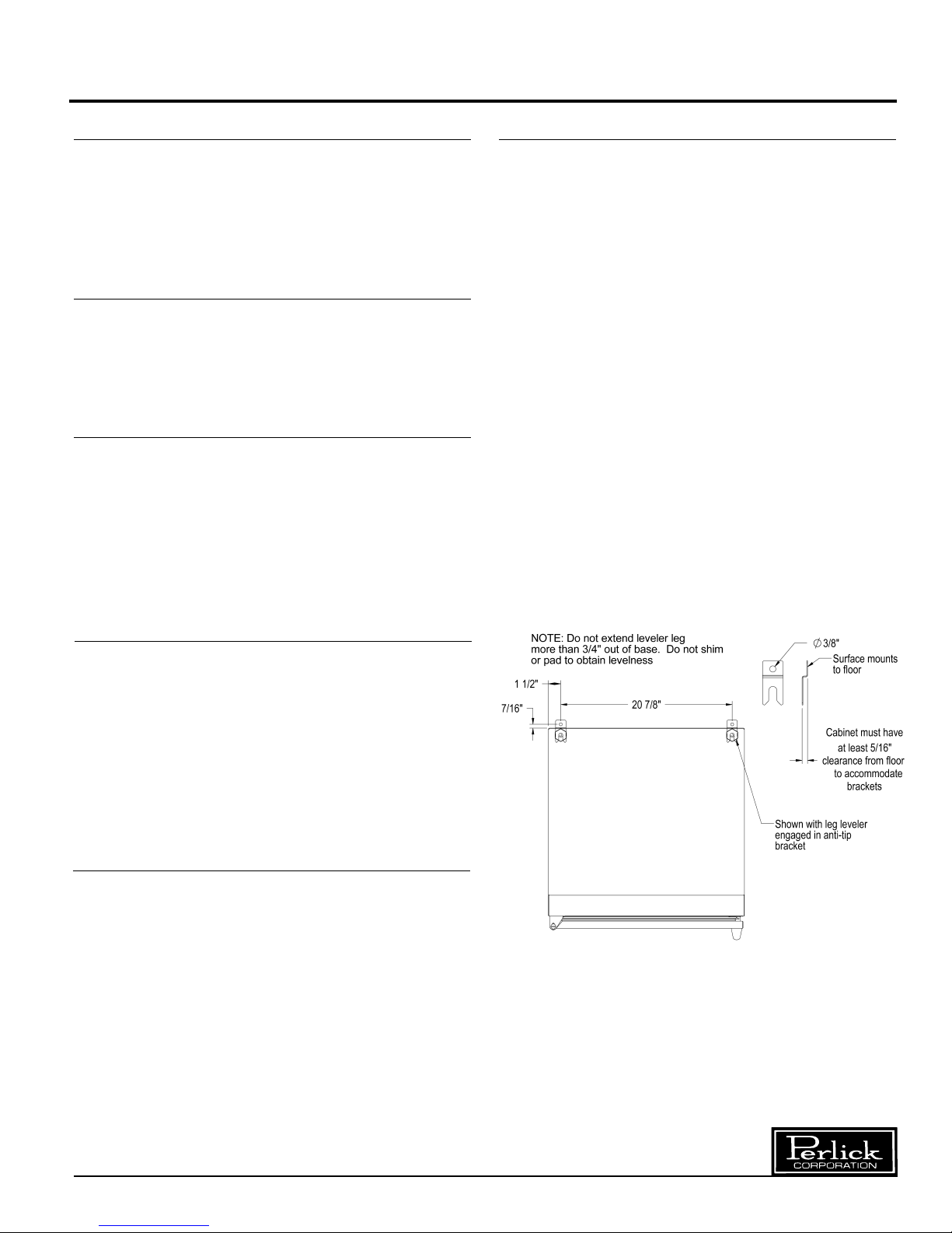
Anti-tip (without Legs or Casters)
To prevent the cabinet from tipping forward and
to provide a stable installation, the cabinet must be
secured in place with an anti-tip device.
A set of metal anti-tip brackets and installation screws
(#10-3/4" wood screw) are supplied. These brackets
should be attached to the floor, at the back of the
cabinet; each bracket located to catch each rear
leveling leg when the cabinet is pushed backward
into position.
THE ANTI-TIP BRACKETS MUST CATCH EACH OF
THE LEVELING LEGS TO HAVE A STABLE AND
SAFE INSTALLATION.
Some installation sites might need to be modified to
provide a secure surface for attaching the bracket.
Refer to the illustration below for anti-tip mounting
bracket locations.
Placing the Cabinet
To assure maximum performance, fresh air must
be allowed to circulate through the machinery
compartment.
cabinet that would obstruct air flow at these grilles.
Do not place the unit in an unventilated small room.
Cabinet should be leveled front to back and side
to side.
Installing Casters or Legs (optional)
Attach casters or legs to the mounting bracket with
the lockwashers and 1/4-20 hex head nuts provided.
Attach bracket and leg/caster assembly to the side
of the cabinet base using the 1/4-20 hex head selftapping machine screws provided.
Do not place anything in front of the
Perlick is committed to continuous improvement. Therefore, we reserve the right to change specifications without prior notice.
3
Form No. Z2255
Rev. 4.19.05
Page 4

Operation Instructions – Single Door Freezer
For sanitation purposes, it may be necessary to
seal the base of the cabinet to the floor. This
can be accomplished by laying a bead of silicone
sealant between the base of the cabinet and the
floor as shown by the figure below.
When sealing the cabinet to the floor, make sure
that the louvered front grille plate can still be
removed for condenser maintenence and cleaning
To activate the six hour defrost system, depress
the defrost switch located on the front grille of the
cabinet. An amber light will illuminate and the
defrost cycle will begin. When the defrost cycle
ends, the light goes off and the cabinet resumes
normal operation. To manually cancel the defrost
cycle, momentarily turn off the electricity to the
machine.
The Four Hour Defrost Timer
This timer ensures that frost will not buildup on the
evaporator coil. Every four hours the hot gas
by-pass valve is opened and hot gas is circulated
through the evaporator coil. The defrost is terminated when the coil is clear of frost. The defrost cycle
lasts for approximately 20 minutes.
During normal operation it is recommended that the
doors are not left open to prevent excessive frost
buildup on the coil.
Temperature Control
An adjustable temperature control is located inside
the froster on the evaporator fan panel assembly.
Approximate temperature operating range: minus
15° F. minimum and plus 10° F. maximum. Make
adjustments as shown to attain the desired
temperature.
■
Colder Temperatures: Turn the adjusting
screw clockwise (to the right).
■ Warmer Temperatures: Turn the adjusting
screw counterclockwise (to the left).
■ Temperature Control “OFF”: Turn the
adjusting screw completely counterclockwise to the “O” position until a click is noted.
Defrost System - Hot Gas Defrost
This system consists of a six-hour, as well as a four
hour cycle which includes a 20 minute evaporator
defrost. The six hour defrost cycle is manually
activated and automatically terminated, while the
four hour cycle is completely automatic.
The Six Hour Solid-State Defrost Timer
This timer shuts off the power to the condensing
unit, the evaporator fan, and the automatic four
hour defrost timer.
Perlick is committed to continuous improvement. Therefore, we reserve the right to change specifications without prior notice.
The condenser fan and the evaporator fan motor
turns off and on with the compressor.
NORMAL
4
3
WARMER
2
1
CONDENSING UNIT
4
6
7
COOLER
8
9
05
Form No. Z2255
Rev. 4.19.05
Page 5

Cleaning Instructions – Single Door Freezer
Cleaning the Condenser:
■ The condenser (located behind the front
grille) should be inspected every 30 days,
and cleaned, if necessary. Failure to keep
the condenser clean will cause a loss in
condensing unit efficiency, or compressor
failure.
Cleaning the Cabinet:
■ Use a damp cloth with a mild detergent and
water to clean the inside and outside of the
cabinet. Dry thoroughly. Do not allow cleaning
agents or large amounts of water to go down
the drain. Use an acceptable stainless steel
polish to clean all stainless steel surfaces.
Never use steel wool or scouring pads to clean
stainless steel.
Avoiding Stainless Steel Corrosion
Corrosion can be prevented by following product cautions, cleaning instructions and avoiding use of certain
chemicals or objects which will cause stainless steel corrosion.
STAINLESS STEEL ENEMY
■ Steel wool or steel scouring pads
■ Cherry/Orange/Olive juice
■ Chlorine Bleach
■ Sharp Objects
Perlick is committed to continuous improvement. Therefore, we reserve the right to change specifications without prior notice.
5
Form No. Z2255
Rev. 4.19.05
Page 6

Replacement Parts
11
10
14
–
Single Door Freezer
21
13
19
17
16
12
CAUTION
15
6
1
20
21
3
2
23
18
4
5
25
33
8
9
22
7
Service should be done by a qualified
refrigeration technician
Disconnect all power before servicing the
cabinet
Perlick is committed to continuous improvement. Therefore, we reserve the right to change specifications without prior notice.
6
Form No. Z2255
Rev. 4.19.05
Page 7

Page 8

Wiring Diagram – Single Door Freezer
Z
8300 West Good Hope Road • Milwaukee, WI 53223 • Phone 414-353-7060 • Fax 414-353-7069
Toll Free 800-558-5592 • E-Mail: Perlick@Perlick.com • www.Perlick.com
Perlick is committed to continuous improvement. Therefore, we reserve the right to change specifications without prior notice.
Form No. Z2255
8
Rev. 4.19.05
 Loading...