

Page 1
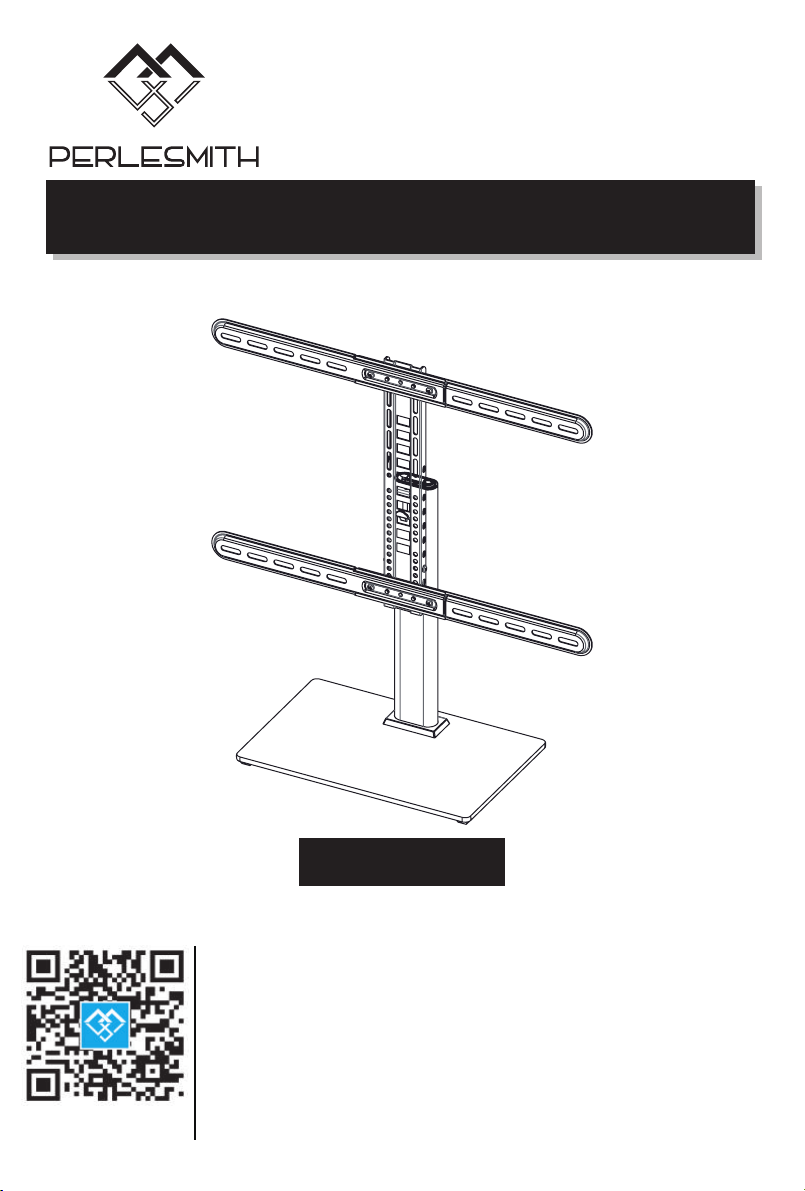
Table Top TV Stand
V2.0
Website:
www.perlesmith.com
Model: PSTVS16
Thank you for choosing this Perlesmith product! At Perlesmith we strive
to provide you with the best quality products and services in the industry.
Please share your experience of our product with others at
www.perlesmith.com/pages/reviews if you are satisfied. Should you have
any issues, please don't hesitate to contact us.
Technical Support:
1-800-556-6806 Mon-Fri 10am - 5pm (PST) (USA) (CAN)
Other Info:
[email protected] (US/CA/DE/UK/FR/IT/ES/AU)
Page 2
IMPORTANT SAFETY INFORMATION
• Please read through these instructions completely before attempting
installation. If you do not understand the instructions or have any concerns
or questions, please contact customer service at
[email protected].
• Check package contents against Supplied Parts and Hardware List to
assure that all components were received undamaged. Do not use damaged
or defective parts. lf you require replacement parts, contact customer
service at [email protected].
• Not all parts and hardware included will be used.
• Do not use this product for any purpose or in any configuration not
explicitly specified in this instruction. We hereby disclaim any liability for
injury or damage arising from incorrect assembly, incorrect mounting, or
incorrect use of this product.
•Please check www.perlesmith.com for more products and company
information.
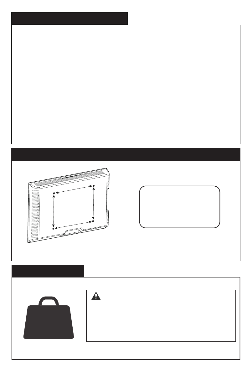
Check the VESA Pattern of TV before the Installation
MAX: 600mm/23.6in.
15.7in.
MAX: 400mm/
Minimum VESA Pattern: 200x100mm(8x4in.)
Weight Restrictions
WARNING:
DO NOT exceed the maximum weight indicated. This
mounting system is intended for use only with the
maximum weights indicated. Use with products heavier
than the maximum weights indicated may result in failure
of the mount and its accessories, causing possible injury.
If your TV weighs more, this mount is NOT compatible.
100 mm ≈ 4 in.
200 mm ≈ 7 7/8 in.
300 mm ≈ 11 3/4 in.
400 mm ≈ 15 3/4 in.
600 mm ≈ 23 6/10 in.
Page 3
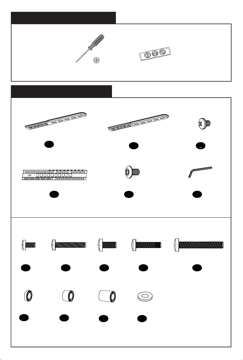
Tools Needed (Not lncluded)
Screw Driver Level
Supplied Parts and Hardware List
TV Bracket I
Height Adjust Bracket
Screw
M6 x 14mm
A x4
Spacer
2.5mm
F x8
a x2
x1
d
Screw
M6 x 35mm
Spacer
10mm
B x4
G x4
Screw
M8 x 25mm
C x4
Spacer
22mm
H x4
TV Bracket II
b x2
Screw BK
M6x10mm
x4
e
Screw
M8 x 35mm
Washer
M6/M8
J x4
Screw BK
M5x6mm
c
x4
Hex Key
4mm
f
x1
Screw
M8 x 50mm
x4D
x4E
1
Page 4
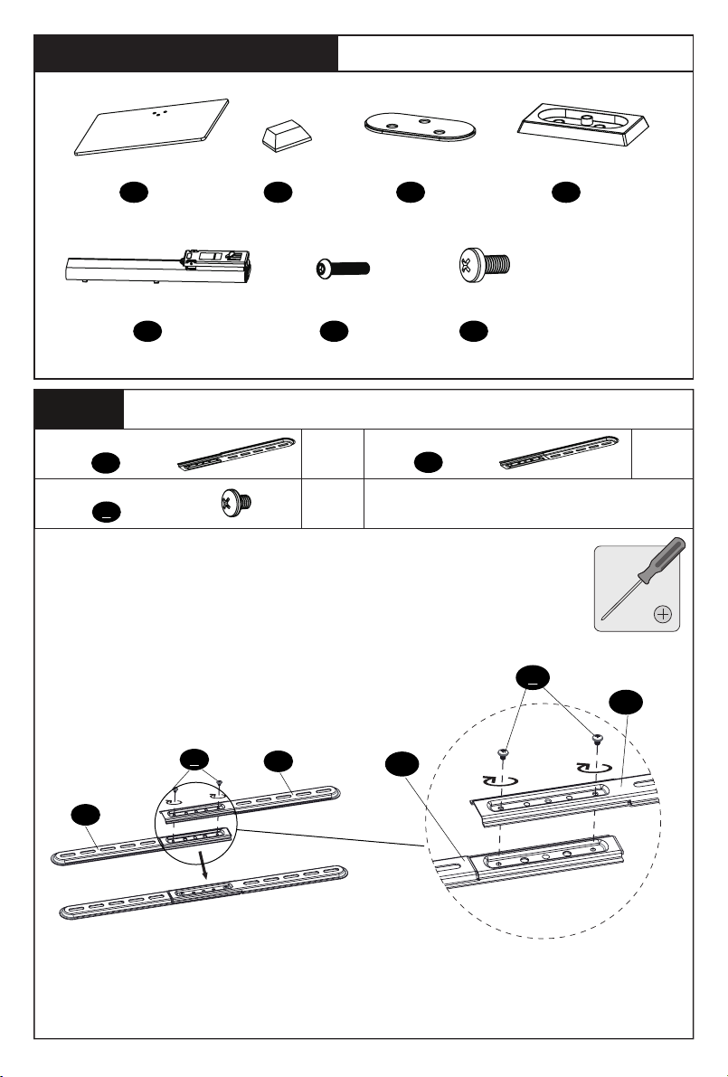
Supplied Parts and Hardware List
Tempered Glass
x1K
Column
O
Step 1
TV Bracket I
Screw BK M5x6mm
Connect the TV Brackets I to Brackets II
a
c
x1
Pad
L
x4
Base Screw BK
M6x30mm
x2
x4
Lock Plate
x3P
TV Bracket II
x1
M
Safety Screw BK
M5x10mm
Q
b
Column Cover
x2
c
x1
N
x2
a
c
b
a
b
2
Page 5
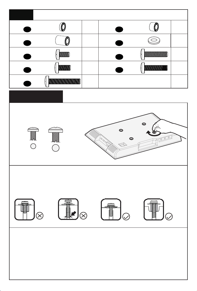
Step 2
Spacer 2.5mm
Spacer 22mm
Screw M6x14mm
Screw M8x25mm
Screw M8x50mm
Attach TV Brackets to TV
F
H
A
C
E
Select TV Screws
Only one screw size fits your TV.
M6 M8
x8
x4
x4 x4
x4
Spacer 10mm
G
M6/M8 Washer
J
Screw M6x35mm
B
Screw M8x35mm
D
x4
x4
x4
x4
Screw length: Verify adequate thread engagement with screws or screws/spacers
combination. We recommend thread engagement by at least 5 turns.
-Too short will not hold the TV.
-Too long will damage the TV.
Too Short
Too Long
Correct
Correct
Note:
1. Only tighten the screws enough to securely fasten TV brackets to TV. DO NOT
overtighten the screws.
2. If necessary, the spacers can be used in multi-layer. If the installation fails after
trying various methods, please contact customer service at supportus@perlesmith.com.
3
Page 6
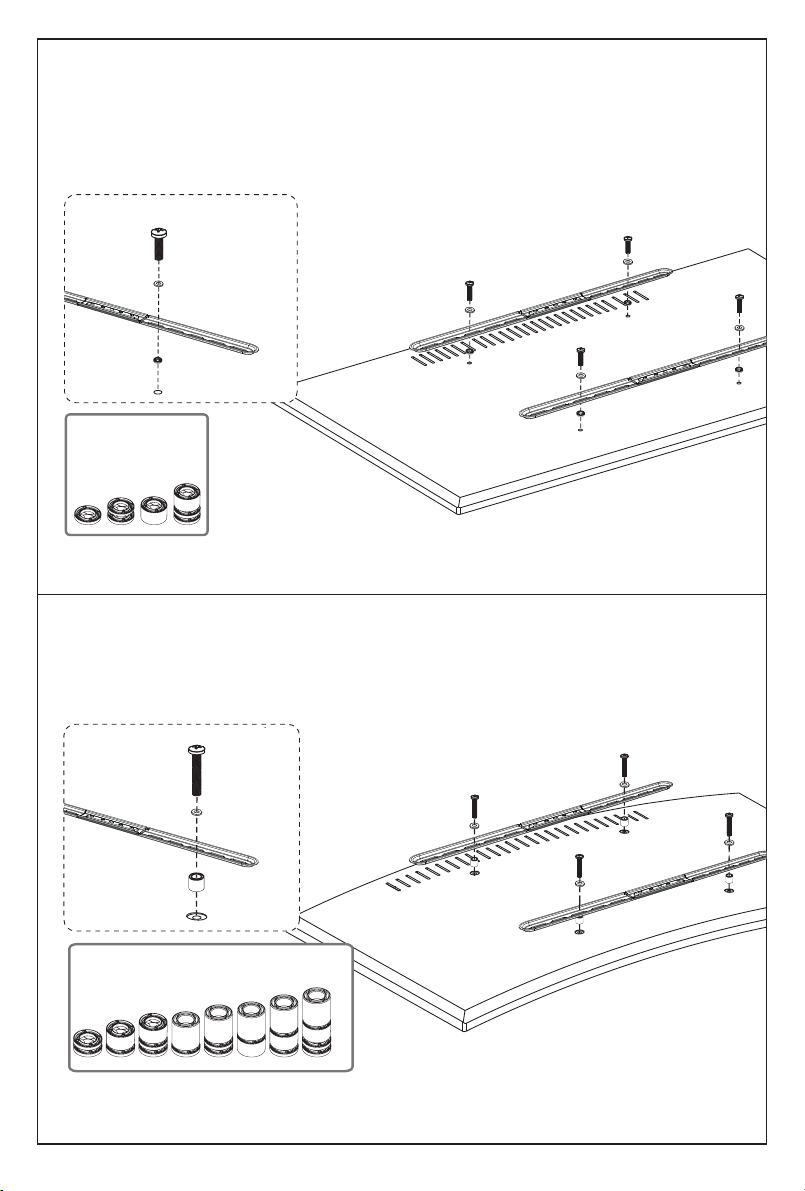
Option A ( For Flat Back TV )
A/C
J
F/G
(If needed)
Alternate
Setups
Spacer
Option B (For Round Back TV)
Alternate
Spacer
Setups
B/D/E
J
F/G/H
4
Page 7
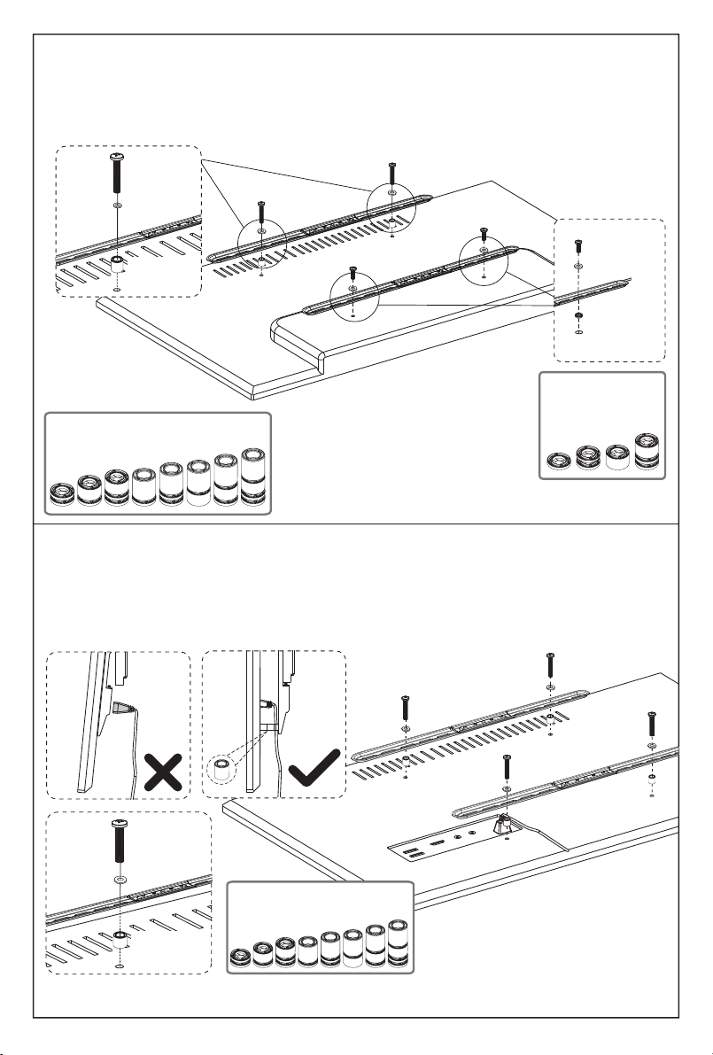
Option C (For TV with A “Bump”)
J
A/C
Spacers may be necessary for 2 holes ONLY.
B/D/E
J
F/G/H
Alternate
Spacer
Setups
Option D
F/G
(If needed)
Alternate
Setups
Spacer
Spacers may be necessary when brackets interfere with cables or USB.
B/D/E
J
F/G/H
Alternate
Spacer
Setups
5
Page 8
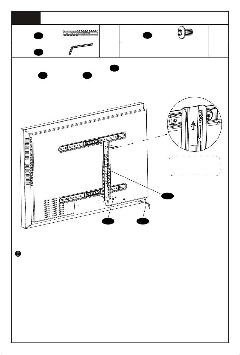
Step 3
Height Adjust Bracket
4mm Hex Key
Secure the height adjust bracket d to TV via TV bracket assembly using
screws e and hex key f
Attach Height Adjust Bracket to TV
d
f
x1
x1
Screw BK M6x10mm
e
Note: Keep the
arrow up
x4
d
fe
IMPORTANT: Ensure all brackets are securely fastened before moving on
to the next step.
6
Page 9
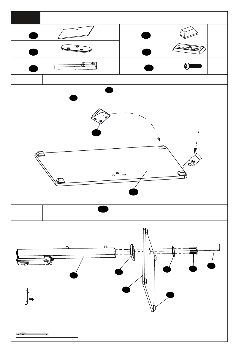
Step 4
Tempered Glass
Lock Plate
Column
Assemble the Base
K
M
O
x1
Pad
x1
Column Cover
Base Screw BK M6x30mm
x1
L
N
P
x4
x1
x3
Step 4-1
Attach the Pads to the Tempered Glass
Peel off the back paper of pads L and attach them to the rough side of
the tempered glass K in the corners
L
Press
K
Step 4-2
Connect Column O to the Smooth Side of the Tempered
Glass
Note: Please adjust
the direction of the
hook on the column
as shown.
O
N
K
M
L
P
f
7
Page 10

Step 5
Safety Screw BK
M5x10mm
Secure TV to Column
Q
x2
Step 5-1
Step 5-2
Hang TV to Column
Note:
If needed, the height of the TV from
the ground can be adjusted.
Lowest
TV Position
Highest
TV Position
HEAVY! You may need
assistance.
Secure TV to Column
Insert the lock screw Q through
the hole on the height adjust
bracekt and that on the column,
then tighten the screw using
screwdriver (not included) to
secure the TV to column
Q
[Not Included]
Q
Q
8
Page 11
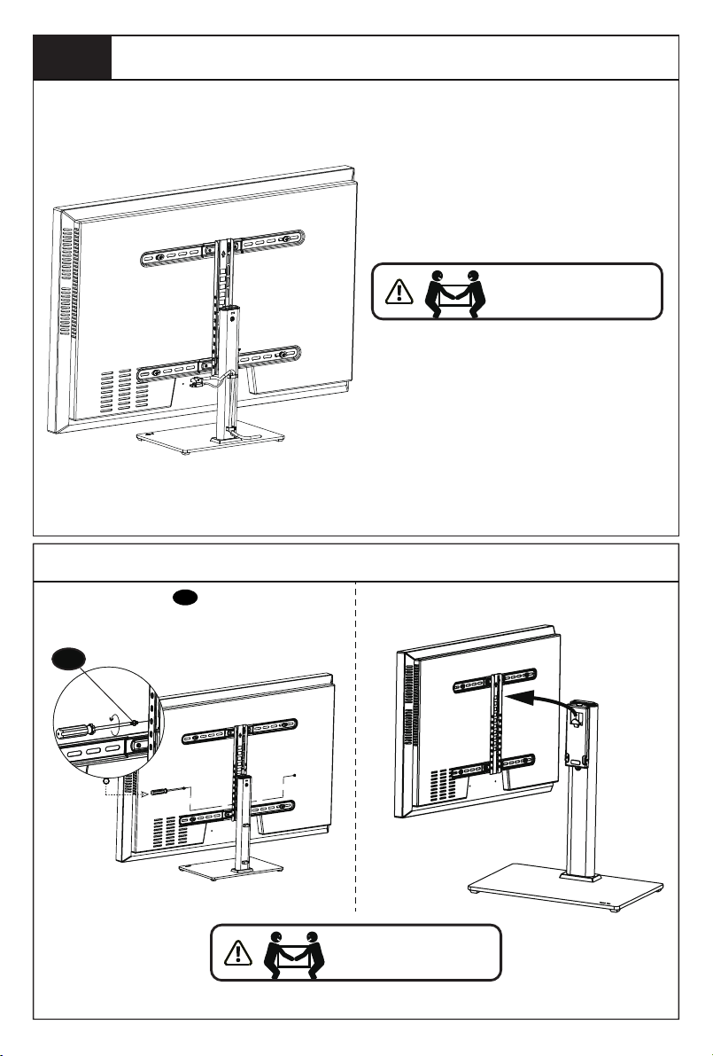
Step 6
Cable Management
Remove Your TV
HEAVY! You may need
assistance with this step.
Remove lock screws Q , and need two people
cooperation to hold the TV at the same time.
Q
HEAVY! You may need
assistance with this step.
Remove TV from the hook on the column
9
Page 12
Thank you again for
choosing this Perlesmith product!
All of us at Perlesmith do appreciate your product purchase. We hope that you are as happy
with your product as we are designing and manufacturing it for you. We strive to provide you
with the best quality products and services in the industry. Please share your experience of our
product with others at www.perlesmith.com/pages/reviews if you are satisfied. Should you
have any issues, please don't hesitate to contact us.
Technical Support: 1-800-556-6806 Mon-Fri 10am - 5pm (PST) (USA) (CAN)
Other Info: [email protected] (US/CA/DE/UK/FR/IT/ES/AU)
Please check www.perlesmith.com for more products and company information.
 Loading...