

Page 1
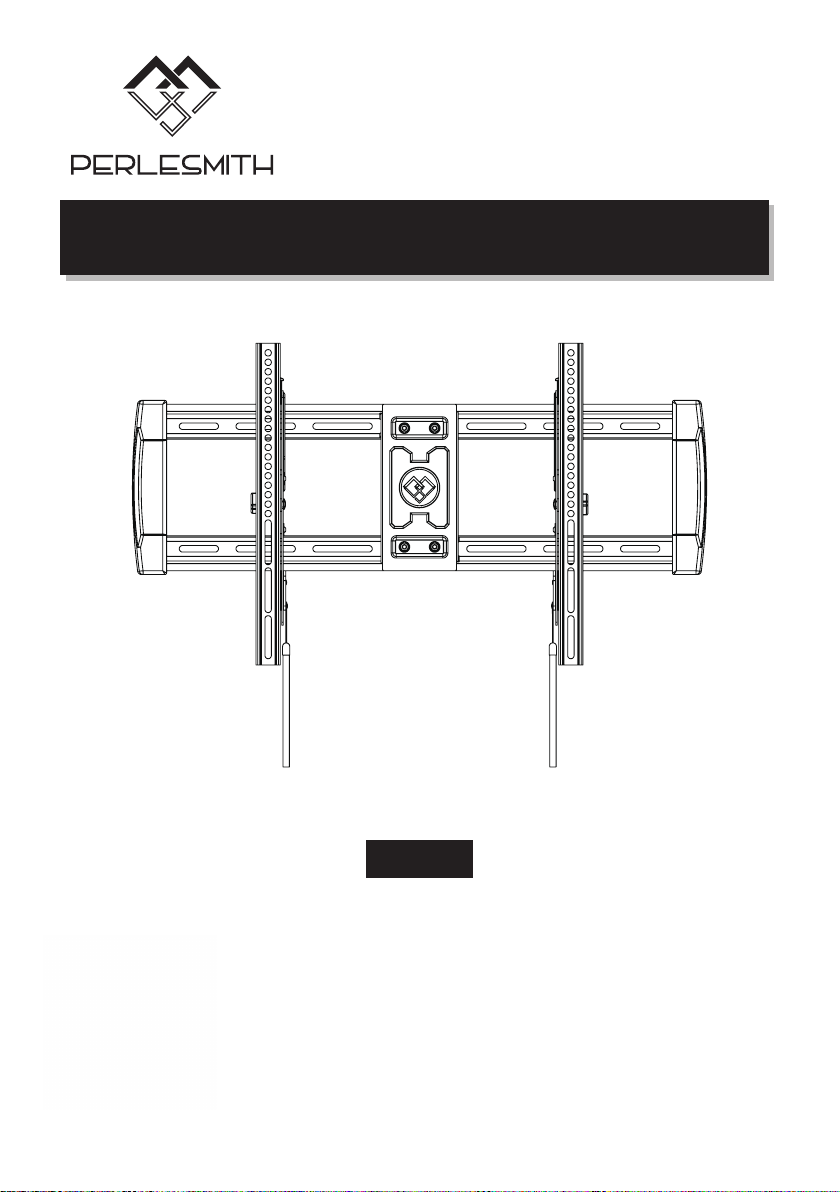
Installation Instructions
V1.0
PSLT3
Thank you for choosing our product! We strive to provide the best
quality and services for our customers. Would you kindly share your
experience on Amazon if you are satisfied? Should you have any
issues, please don't hesitate to contact us.
Telephone:
800-5566-806 Mon-Fri 10am - 6pm (PST) (USA) (CAN)
Email:
[email protected] (US/CA/DE/UK/FR/IT/ES/JP/AU)
Page 2
IMPORTANT SAFETY INFORMATION
•Check package contents against Supplied Parts and Hardware Lists to assure that all
components were received undamaged. Do not use damaged or defective parts.lf you
require replacement parts, contact customer service at [email protected]
•Not all parts and hardware included will be used.
•Carefully read all instructions before attempting installation.If you do not understand the
instructions or have any concerns or questions, please contact customer service at
[email protected]
•This product may contain moving parts. Use with caution.
•Do not use this product for any purpose or in any configuration not explicitly specified in
this instruction. We hereby disclaim any liability for injury or damage arising from
incorrect assembly, incorrect mounting, or incorrect use of this product.
•DO NOT INSTALL INTO DRYWALL ALONE.
•Please check www.perlesmith.com for more products and company information.
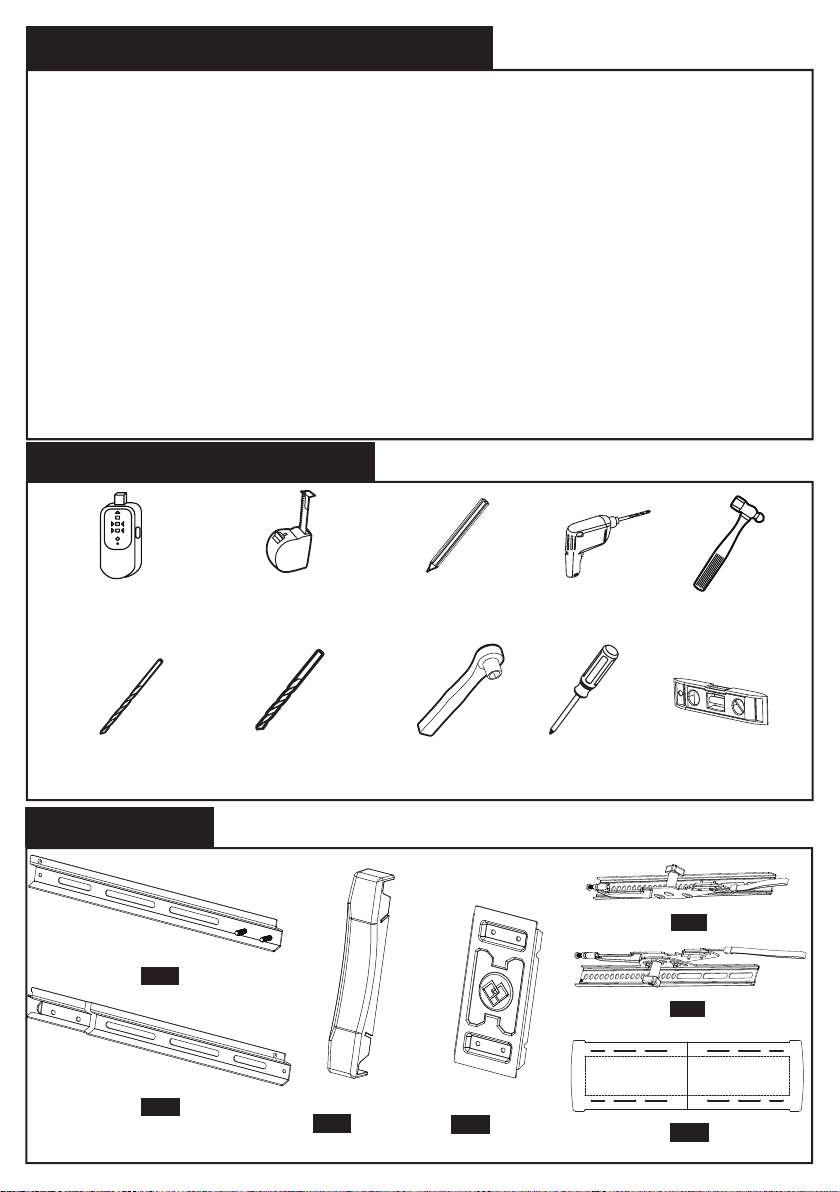
Tools Needed (Not lncluded)
Stud Finder Tape measure
5mm
Wood Drill
10mm
Concrete Drill
Supplied Parts
Back Rail
Front Rail
01
02
x2
x2
socket wrench
Plastic Cover
03
x2
Pencil Drill
Screw Driver
Wall Plate
04
x1
1
TV Bracket
TV Bracket
Wall Plate
Template
Hammer
level
05
x1
06
x1
07
x1
Page 3
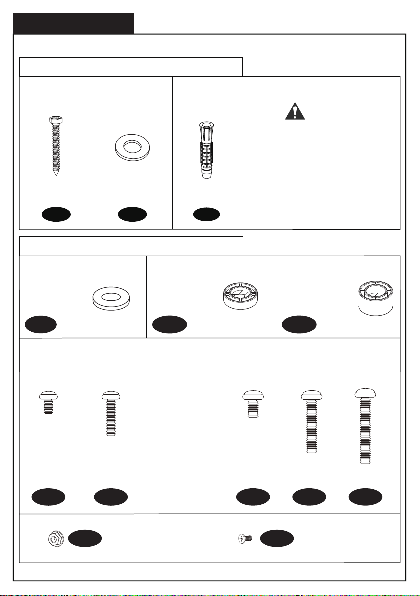
Supplied Hardware
Hardware for Attaching Wall Plate to Wall
Lag Bolts
M8X65
x4 x4
A1
Washers
M8
x4
A2
Wall
Anchor
A3
Hardware for Attaching TV Bracket to TV
Spacer with
M6/M8
B
Philips Screws
M6X15mm
M6X30mm
x4
Spacers
5mm
C1
These anchors are for
concrete or brick walls
ONLY. DO NOT use them
in drywall or wood studs.
x8
Philips Screws
M8 x 15mm
M8 x 45mm
M8 x 65mm
CAUTION!
Spacers
10mm
C2
x8
x4x4
D1 D2
F1 F2
x4
E1
M6 Nut X4 ST4.2X10 X4
x4
E2
x4
E3
2
Page 4
Step 1
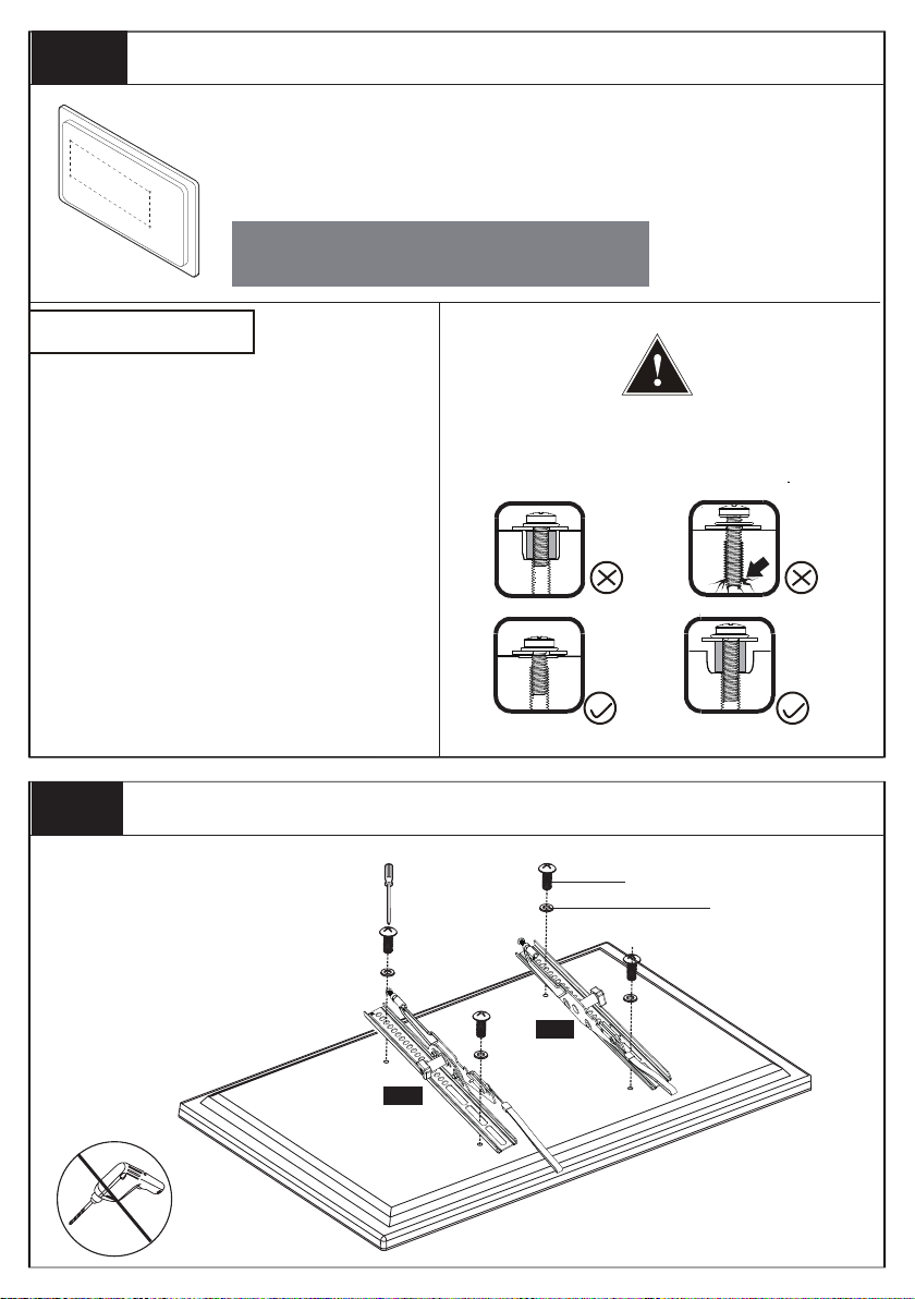
Measure VESA and Check TV screws
Measure the distance between the holes located at the back of your TV
(these measures may form the shape of a square, or a rectangle) and
Width
Height
check that these taken measurements are within the VESA(*) range for
this wall mount.(*)
VESA: International standard established by the TV manufacturers used to
determine if LCD/LED TVs are compatble with wall mounts.
100 mm ≈ 4 in
300 mm ≈ 11 3/4 in
600 mm ≈ 23 6/10 in
Check TV screws
Hand thread screws into the threaded
inserts on the back of your TV to
determine which screw diameter (M6, or
M8) to use.
200 mm ≈ 7 7/8 in
400 mm ≈ 15 3/4 in
When attaching brackets to the flat screen, be
careful not to over tighten screws and be sure that
screws do not bottom out in the mounting holes.
Step 2
For FLAT TV
Manual Only!
Attach the TV Brackets to Your TV
Top of TV
05
06
Too Short
Correct
D1/E1
Too Long
Correct
B
Bottom of TV
3
Page 5
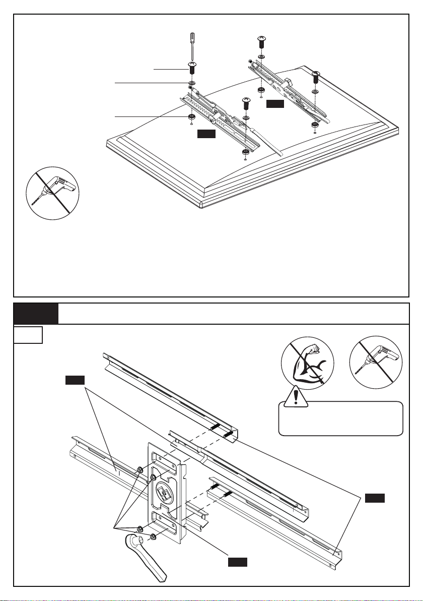
For Flat TV with Inset Holes or Cable Interference or Rounded TV
D2/E2/E3
B
Top of TV
05
C1/C2
06
Manual Only!
Bottom of TV
First, make sure the diameter of the bolt(D1-E3) fits your TV. Then, please see
the diagram above. You will need to thread the bolt into the TV using the washer
(B) and spacer (C1 or C2) if necessary with a screwdriver(Not included). Please
make sure the monitor brackets(05/06) are vertically centered and level with
each other.
Step 3
3-1
Assemble Wallplate
02
DO NOT overtighten.
Tighten only until snug.
01
F1
04
4
Page 6
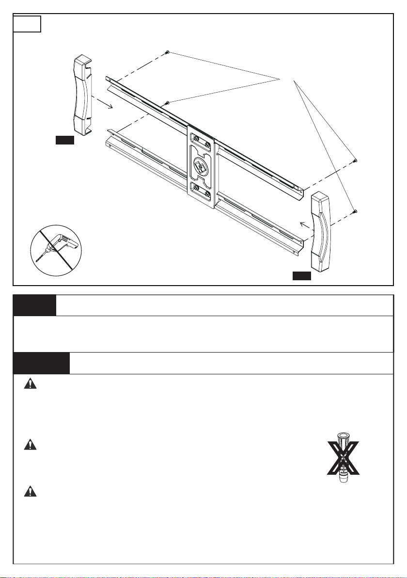
3-2
Manual Only!
F2
03
03
Step 4
For wood stud installation, follow STEP 4A
For concrete installation, follow STEP 4B
Step
Avoid potential personal injury or property damage! DO NOT
over-tighten the lag bolts [A1]. Tighten the lag bolts [A1] only until the
washers [A2] are pulled firmly against the wall plate.
Ensure the wall plate is securely fastened to the wall
before continuing on to the next step.
● Any material covering the wall must not exceed 5/8 in. (16 mm)
● Nominal wood stud size: common 2 x 4 in. (51 x 102 mm) minimum
1½ x 3½ in. (38 x 89 mm)
● Stud center must be verified
Attach Wall Plate to Wall
4A
WARNING:
WARNING:
WARNING:
Wood Stud Option
X
5
Page 7
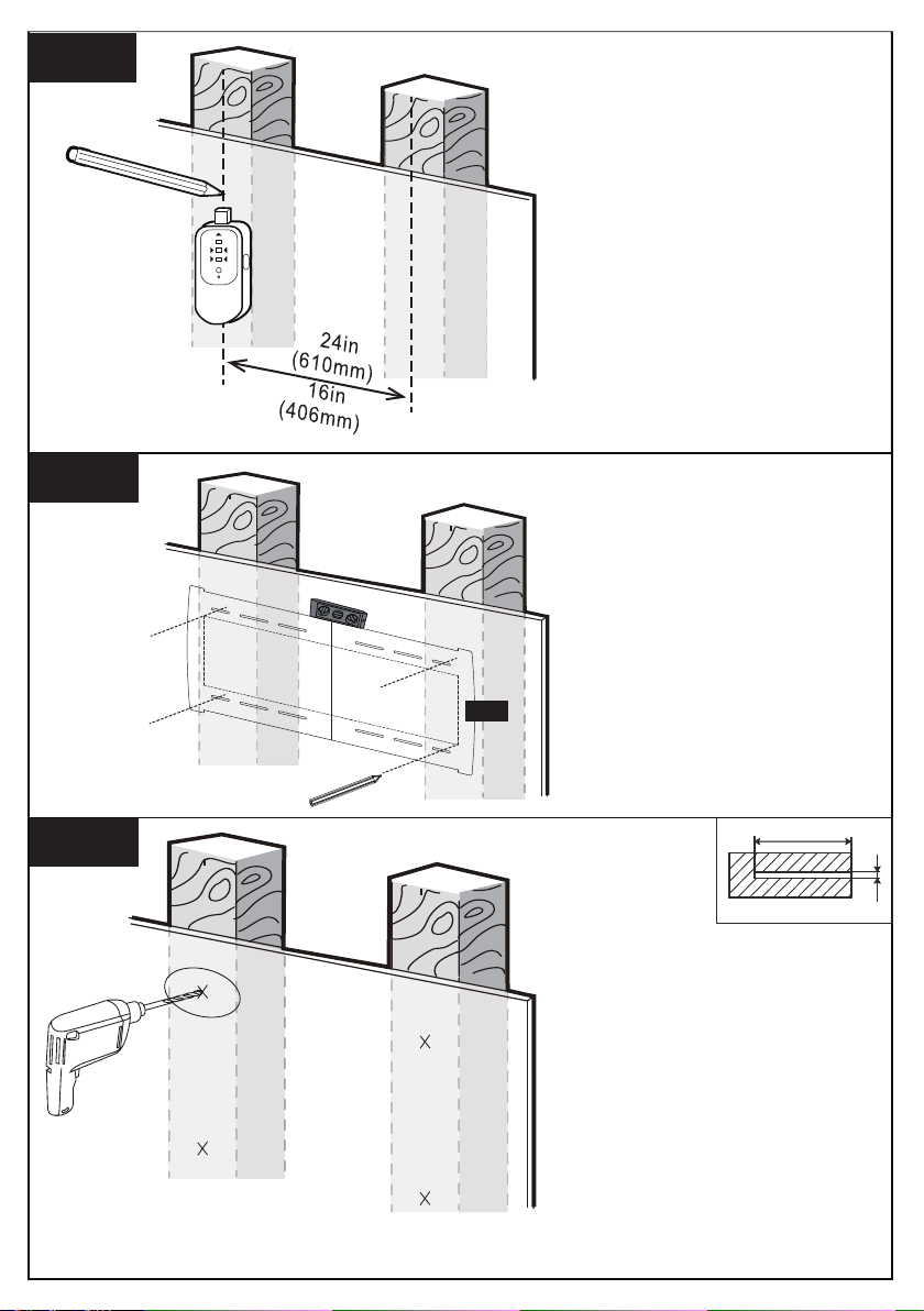
4A-1
4A-2
07
Use a stud finder(not
included) to locate wood
studs. Mark the edge and
center locations.
Position the template at
your desired height and
line up the holes with your
stud center line. Level the
template and mark the
holes.
4A-3
65mm
ø5mm
Drill 4 pilot holes using a
5 mm diameter drill bit.
Make sure the depth is
not less than 65mm.
6
Page 8
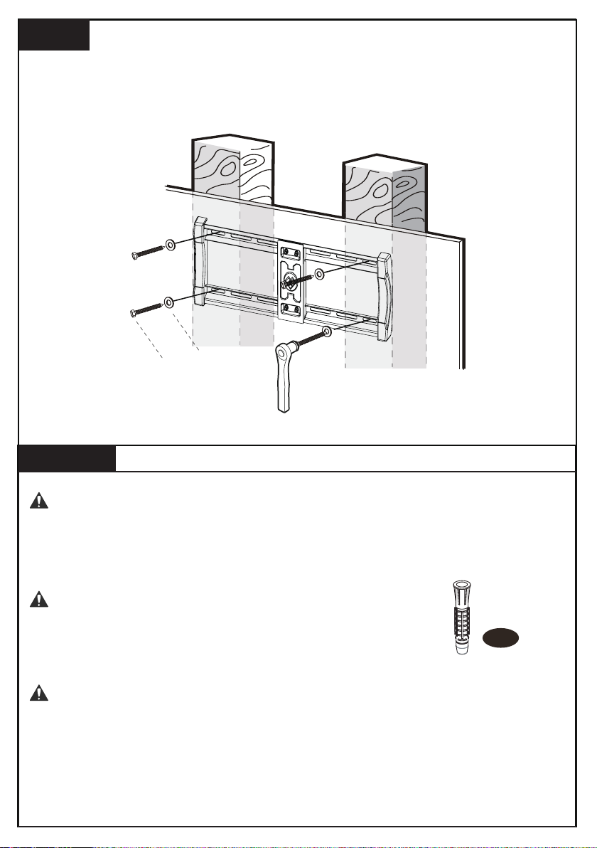
4A-4
Install the wall plate using lag bolts [A1] and washer [A2]. Tighten
the lag bolts [A1] only until the washers [A2] are pulled firmly
against the wall plate.
A2
A1
Step
4B
Solid Concrete or Concrete Block Option
WARNING:
Avoid potential personal injury or property damage!
over-tighten the lag bolts [A1]. Tighten the lag bolts [A2] only until the
washers [A2] are pulled firmly against the wall plate
WARNING:
Ensure the wall plate is securely fastened to the wall
before continuing on to the next step.
DO NOT
.
Wall
Anchor
A3
WARNING:
● Any material covering the wall must not exceed 5/8 in. (16 mm)
● Mount the wall plate directly onto the concrete surface
● Minimum solid concrete thickness: 203 mm (8 in.)
● Minimum concrete block size: 203 x 203 x 406 mm (8 x 8 x 16 in.)
7
Page 9
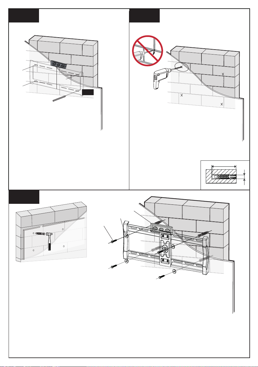
4B-1 4B-2
07
Drill 4 pilot holes using a 10mm
diameter drill bit. Make sure the
Position the template at your desired
height, level the template and mark
the pilot hole locations.
depth is not less than 70mm Never
drill into the mortar between blocks.
70mm
ø10mm
4B-3
Use the hammer to
knock anchors [A3]
into the wall.
Install wall plate using lag bolts [A1], washers [A2] and anchors
[A3]. Be sure the anchors [A3] are seated flush with the concrete
surface. Tighten the lag bolts [A1] only until the washers [A2] are
pulled firmly against the wall plate. DO NOT over-tighten the lag
bolts [A1].
A1
A2
A3
8
Page 10
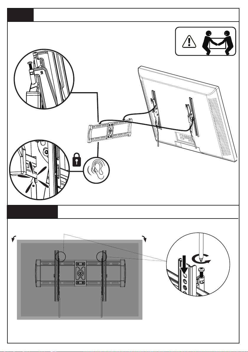
Step 5
Hang Your TV to the Wall Plate
HEAVY! You may
need assistance
with this step.
Adjustment 1
Level
9
Page 11
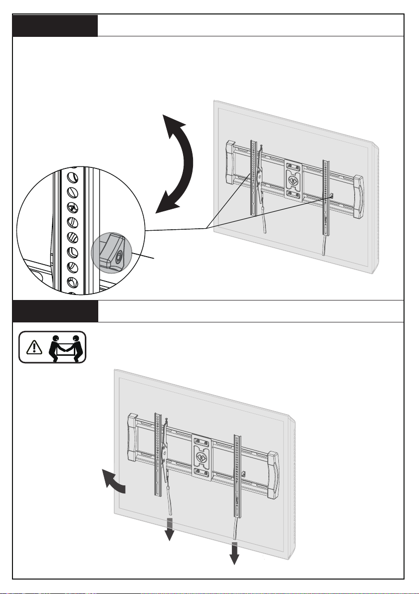
Adjustment 2
Your TV should adjust easily when moved, then stay in place. If your
TV is too loose or too tight, adjust side tension knob [T] .
NOTE: Once your TV is in place, tighten the side tension knob [T] to
prevent unwanted movement.
Tilt Angle Adjustment
T
Adjustment 3
HEAVY! You may need assistance with this step.
Remove
10
Page 12

Thank you for choosing our product! We strive to provide the
best quality and services for our customers. Would you kindly
share your experience on Amazon if you are satisfied? Should
you have any issues, please don't hesitate to contact us.
Telephone:
800-5566-806 Mon-Fri 10am - 6pm (PST) (USA) (CAN)
Email:
[email protected] (US/CA/DE/UK/FR/IT/ES/JP/AU)
 Loading...