

Page 1
Introduction
The IOLAN SDS W is offered as a 1-port and 2-port unit with
DB9M connector/s and as a 4-port RJ45 model. All models
provide Serial to Wi-Fi, Serial to Ethernet and Ethernet to
Wi-Fi connectivity. Each model has industry standard wireless
networking using 802.11 a/b/g/n with robust configurable
wireless security methods of WEP, WPA-Personal,
WPA2-Personal, Enterprise (EAP, PEAP, LEAP) and 802.11i.
This guide covers the basic installation and configuration of
your IOLAN SDS W. It is intended for systems administrators.
Setup Steps for the IOLAN
1. Verify that you have all the required components.
2. Connecting the Hardware.
3. Connecting the IOLAN to the Wi-Fi network.
4. Configuring the IOLAN.
For detailed information, please refer to the IOLAN User’s
Guide for your model.
Components
What’s In the Box
IOLAN SDS W
• 1 or 2 RP-SMA Antennas
• A Quick Start Guide (this document)
• Power cord strain relief strap and rubber feet
• Wall mount brackets
• A CD-ROM containing documentation and firmware
required to configure and operate the IOLAN SDS
What You Need to Supply
• Serial cable(s) to connect your serial devices to the IOLAN
SDS (depending on your model).
• An Ethernet 10/100/1000BASE-T cable to connect the
IOLAN to the network (if applicable).
Connecting the Hardware
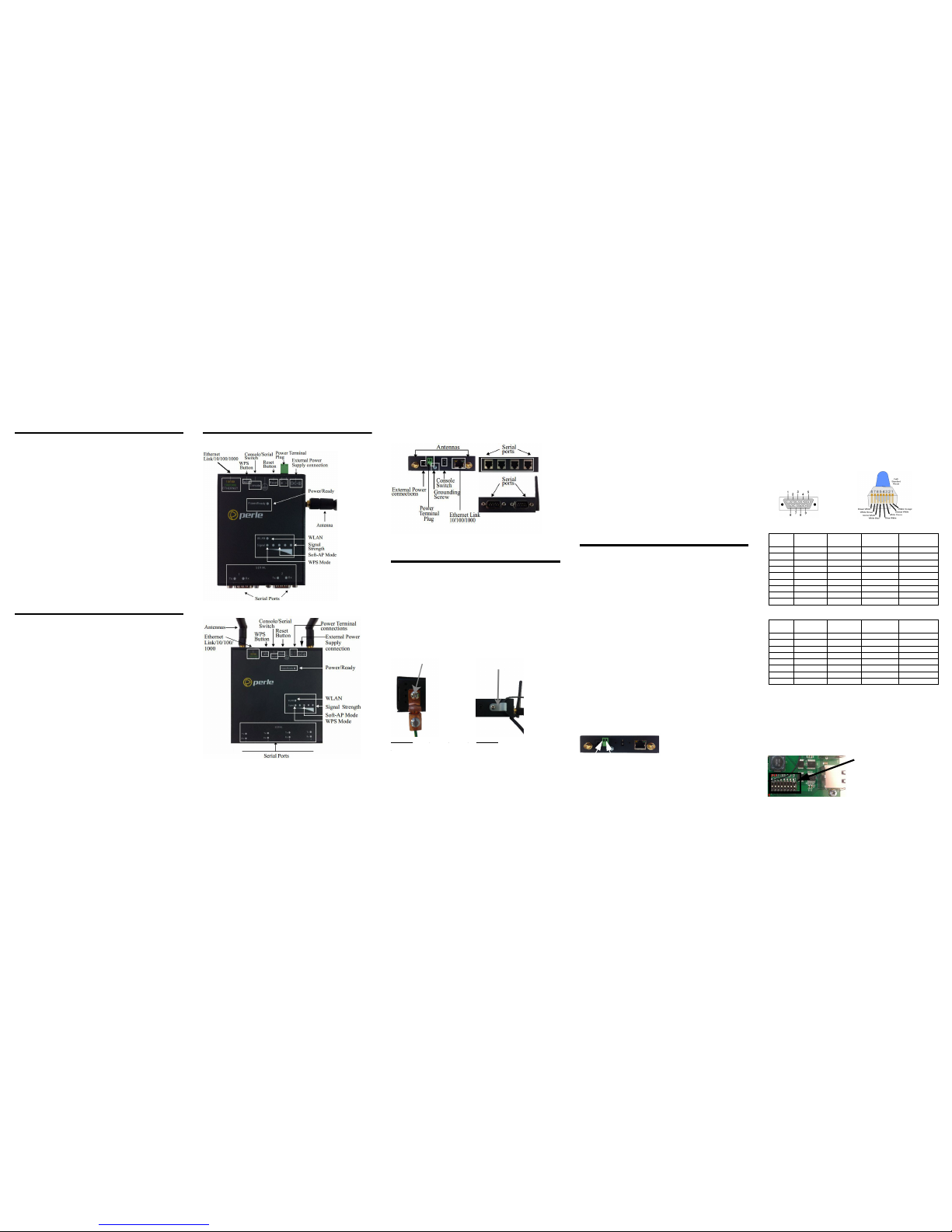
IOLAN SDS 1 or 2 W Top View
IOLAN SDS4 W Top View
Note- The first yellow light (from the left) within the signal strength
LED display will pulse when the unit is in WPS mode.
Note- The third green light within the signal strength LED display
will pulse when the unit is in Soft-AP Mode.
IOLAN SDS End View
Connecting the Hardware
1. Connect the Wi-Fi antenna/s by simply screwing the
antenna/s onto the connectors on the IOLAN.
2. Connect the Ethernet cable from the RJ-45 plug
(10/100/1000) to the HUB or switch that will provide
network connectivity (if applicable to your application).
3. The console dip switch on the IOLAN should be set to the
down position for serial mode.
4. Connect the power cord strain relief, if desired. (Figure 1)
5. Connect the grounding lug (not provided) to the grounding
screw, if desired. (Figure 2)
Figure 1 Figure 2
Button/Switch Functions
Reset Button
To reset the IOLAN insert a paper clip into the inset hole
labelled as Reset and gently press inwards. The Power/Ready
LEDs on the IOLAN will go On and then momentarily Off
when released to show that the unit has been reset. All links
will be dropped and the MAC tables will be cleared
WPS Button
Insert a paper clip into the inset hole labelled as WPS and
gently press inwards. Pressing this button for less then 3
seconds will put the IOLAN in WPS mode, greater then 4
seconds the unit is in Soft-AP mode.
Console Switch
The dip switch on the IOLAN is set in the factory to serial
(down position). Unless you plan to attach a console to the
IOLAN, leave the dip switch in the serial position.
Connecting the Power
Either the barrel or TB (Terminal Block) can be used to
power the IOLAN.
Barrel connector
• Plug the power adapter into a power socket and connect
the barrel connector end into the IOLAN. The
power/Ready LED should show a solid green.
Terminal block connector
1. Ensure power is NOT applied to the wires prior to
connection.
2. On each end wire (12-20 AWG), remove the insulation from
the copper wire 5 mm (3/16 of an inch).
3. Loosen the left screw on the top of the terminal connector
block, then insert your positive (+) wire into the left
terminal and screw it down tight (.51Nm torque). Loosen
the right screw on the top of the terminal connector block,
then insert your negative (-) wire into the right terminal and
screw it down tight (.51Nm torque).
4. Re-insert the terminal block connector if removed.
5. Turn on power at source.
Input Voltage Range: (9-30v DC).
Typical Power Consumption @ 12v DC;
IOLAN SDS1 W Nominal 0.3A@12V, Max 0.45A, Max 4.5W
IOLAN SDS2 W Nominal 0.33A@12V, Max 0.5A, Max 5.1W
IOLAN SDS4 W Nominal 0.39A@12V,Max 0.66A, Max 6.4W
DB9M / RJ-45 Connectors
Please refer to the pin-out table for your device and ensure you
have the appropriate cable for connecting your serial device to
serial ports on the IOLAN.
DB9M Socket
RJ-45 Socket
Each serial port can operate in either EIA 232, 422 or 485 mode. This
is a software configuration. If EIA 422 or 485 is selected, the line termination may need to be set. SW5 has two switches associated with
each serial port.
Note: For EIA-232 these switches must be in the OFF position
(default).
RX Termination: First Switch of Pair ON
TX Termination: Second Switch of Pair ON
Power Cord
Strain relief clip
Grounding
screw
Left - Right +
Pinout RS232
RS485
Full Duplex
RS485
Half Duplex RS422
1 (out) DCD - - 2 (out) RxD R xD+ - RxD+
3 (in) TxD TxD+ DATA+ TxD+
4 (in) DTR - - 5 GND GND GND GND
6 (out) DSR RxD- - RxD7 RTS - - 8 (out) CTS - - 9 - TxD- DATA- TxD-
Pinout EIA-232
RS485
Full Duplex
RS485
Half Duplex RS422
1 (out) DCD - - 2 (in) RTS TxD+ DATA+ TxD+
3 (out) DSR - - 4 (in) TxD TxD- DATA- TxD5 (out) RxD RxD+ - RxD+
6 GND GND GND GND
7 (out) CTS RxD- - RxD8 (in) DTR - - -
DB9M
RJ-45
J5
Switch 1 and 2 - Port 1
Switch 3 and 4 - Port 2
Switch 5 and 6 - Port 3
Switch 7 and 8 - Port 4
Page 2
Powering On Cycle
When the power is connected to the IOLAN, the Power/Ready
LED will cycle through several sequences and will end in a
solid green once the unit is fully booted and ready to be
configured.
If the LED is not solid green after two minutes, refer to the
User’s Guide for help identifying the reason.
LED Guide
Power/Ready—(Green/Yellow/Red)
•Green—
• Solid — System Ready
• Flashing — System is booting or dip switch is in console
mode
• Yellow—
• Flashing — Booting
• Red—Error condition (refer to the User’s Guide for details)
Link/10/100/1000 (on Ethernet Link Connector)
• Green—1000 Mbits (flash with activity)
• Green/Amber—100 Mbits (flash with activity)
• Amber—10 Mbits (flash with activity)
• Off—no LAN connection
WPS (Wi-Fi Protected Setup)
• Yellow pulsing —The first yellow LED within the signal
strength LED display will pulse on and off
Soft-AP Mode (Access Point Mode)
• Green pulsing —The third green light within the signal strength
LED display will pulse on and off
WLAN
• Solid Green— A wireless connection has been established
• Green pulsing —Data is being transmitted over the wireless
network
• Off—no wireless connection is established
Signal
• Wireless signal strength from amber leds to green leds with green
being the strongest signal strength
Serial Activity
• Tx—Flashes with transmit serial activity
• Rx—Flashes with receive serial activity
Connecting the IOLAN to the Wi-Fi
Network
The following steps allow for each connection to the IOLAN for
initial configuration.
Initial Setup - Soft-AP Method
1. The IOLAN must be powered up.
2. Press the inset WPS button (using a paper clip) for 4
seconds to enable Soft-AP mode. The Signal strength LED
display should show a pulsing green LED on the third light
from the left to right to confirm you are in Soft-AP mode
(See IOLAN Top Views).
3. The IOLAN is listed on your network connections on your
PC or wireless client. It will appear as SSID:
IOLAN-xxxxxx (the last 6 digits of the IOLAN wireless
MAC address - found on the product label).
4. If using the password entry method:
• select the wireless network on the PC
• when a password is requested, enter the password
printed on the product label
5. If using the WPS method:
• press and release the WPS button on the IOLAN
• select the wireless network on the PC
• select the WPS option on the PC’s password dialog box
6. Should a dialog box appear on your PC’s screen to connect
to the network, press the continue/Ok button to complete
the connection to the IOLAN.
7. Use a Web browser to connect to the default address of the
IOLAN at (192.168.0.1).
8. The default userid is admin and the default password is
superuser (case sensitive).
9. You can now configure and manage your IOLAN using
the IOLAN WebManager application.
Note: You should change the admin password to restrict
unauthorized access to your IOLAN.
For additional methods of configuring your IOLAN (i.e.,
HTTP, Telnet, SNMP), please refer to the IOLAN User’s
Guide.
Registering the IOLAN
You should register your IOLAN online at:
http://www.perle.com/support_services/warranty_reg.asp
IOLAN SDS W Technical Specifications
IOLAN
SDS W
1/2/4-Port
Quick Start Guide
• Serial to Wi-Fi
• Serial to Ethernet
• Ethernet to Wi-Fi
• Universal, software selectable EIA-232/422/485 interface
• 15 KV ESD protection
SDS 1W SDS 2W SDS 4W
Operating
Temperature
-40°C to 75°C
-40°F to 167°F
-40°C to 75°C
-40°F to 167°F
-40°C to 75°C
-40°F to 167°F
Storage
Temperature
-40°C to 85°C
-40°F to 185°F
-40°C to 85°C
-40°F to 185°F
-40C to 85 C
-40°F to 185°F
Operating and
Storage Humidity
5 to 95% (non
condensing)
5 to 95% (non
condensing)
5 to 95% (non
condensing)
Weight .24 Kg .24 Kg .40 Kg
Dimensions
90 cm by 76
cm by 24 cm
35.43 in. by
29.92 in. by
43.31 in.
90 cm by 76
cm by 24 cm
35.43 in. by
29.92 in. by
43.31 in.
110 cm by 111
cm by 24 cm
43.31 in. by
43.70 in. by
43.31 in.
Contacting Perle Technical Support
Perle offers free technical support to Perle Authorised
Distributors and Registered Perle Resellers.
To access technical support, please visit the Perle
website at www.perle.com/support.
Here you will find:
• latest drivers and firmware updates for download
• technical tips
• frequently asked questions
• documentation
• configuration support
• cabling information
• maintenance contract information
• and much more...
If you are unable to find the information you require,
please feel free to contact our technical support teams
by email at:
USA
Email: [email protected]
Europe
Email: [email protected]
Asia
Email: [email protected]
Internet
www.perle.com/support_services
IOLAN SDS W
1/2/4-Port Quick Start Guide
Part No:
5500346-10 (Rev A)
Copyright © Perle Systems Limited, 2016
 Loading...