

Page 1

Models Covered:
RPS820
RPS830
RPS1620H
RPS1630H
5500193-12
RPS Series
Remote Power Switches
User's Guide
Page 2

Warnings and Cautions:
Installation Instructions
Secure Racking
If Secure Racked units are installed in a closed or multi-unit rack assembly, they may require
further evaluation by Certication Agencies. The following items must be considered.
1. The ambient within the rack may be greater than room ambient. Installation should be
such that the amount of air ow required for safe operation is not compromised. The
maximum temperature for the equipment in this environment is 55°C. Consideration
should be given to the maximum rated ambient.
2. Installation should be such that a hazardous stability condition is not achieved due to
uneven loading.
3. Side vents are used to dissipate heat generated within the unit. When mounting the unit in
an equipment rack, make certain to allow adequate clearance for venting.
Input Supply
Check nameplate ratings to assure there is no overloading of supply circuits that could have an
effect on overcurrent protection and supply wiring.
Grounding
Reliable earthing of this equipment must be maintained. Particular attention should be given to
supply connections when connecting to power strips, rather than direct connections to the
branch circuit.
No Serviceable Parts Inside; Authorized Service Personnel Only
Do not attempt to repair or service this device yourself. Internal components must be serviced by
authorized personnel only.
• ShockHazard-DoNotEnter
• LithiumBattery
CAUTION:Dangerofexplosionifbatteryisincorrectlyreplaced.Replaceonlywith
sameorequivalenttyperecommendedbythemanufacturer.Discardusedbatteries
accordingtothemanufacturer'sinstructions.
Disconnect Power
If any of the following events are noted, immediately disconnect the unit from the outlet and
contact qualied service personnel:
1. If the power cord becomes frayed or damaged.
2. If liquid has been spilled into the device or if the device has been exposed to rain or water.
Two Power Supply Cables
Note that RPS series units feature two separate power circuits, and a separate power supply cable
for each power circuit. Before attempting to service or remove his unit, please make certain to
disconnect both power supply cables are disconnected.
i
Page 3

Agency Approvals
FCC Part 15 Regulation
This equipment has been tested and found to comply with the limits for a Class A digital device,
pursuant to part 15 of the FCC Rules. These limits are designed to provide reasonable protection
against harmful interference when the equipment is operated in a commercial environment. This
equipment generates, uses, and can radiate radio frequency energy and, if not installed and used in
accordance with the instruction manual, may cause harmful interference to radio communications.
Operation of this equipment in a residential area is likely to cause harmful interference in which
case the user will be required to correct the interference at his own expense.
This device complies with part 15 of the FCC Rules. Operation is subject to the following two
conditions: (1) This device may not cause harmful interference, and (2) this device must accept
any interference received, including interference that may cause undesired operation
WARNING: Changes or modications to this unit not expressly approved by the party
responsible for compliance could void the user’s authority to operate the equipment
EMC, Safety, and R&TTE Directive Compliance
The CE mark is afxed to this product to conrm compliance with the following European
Community Directives:
• CouncilDirective89/336/EECof3May1989ontheapproximationofthelawsof
MemberStatesrelatingtoelectromagneticcompatibility;
and
• CouncilDirective73/23/EECof19February1973ontheharmonizationofthelaws
ofMemberStatesrelatingtoelectricalequipmentdesignedforusewithincertain
voltagelimits;
and
• CouncilDirective1999/5/ECof9Marchonradioequipmentandtelecommunications
terminalequipmentandthemutualrecognitionoftheirconformity.
ii
Page 4

Table of Contents
1. Introduction. . . . . . . . . . . . . . . . . . . . . . . . . . . . . . . . . . . . . . . . . . . . . . . . . . . . . . . . . . . . . . . . . . . . . 1-1
2. UnitDescription . . . . . . . . . . . . . . . . . . . . . . . . . . . . . . . . . . . . . . . . . . . . . . . . . . . . . . . . . . . . . . . . . 2-1
2.1. RPS Front Panel . . . . . . . . . . . . . . . . . . . . . . . . . . . . . . . . . . . . . . . . . . . . . . . . . . . . . . . . . . . . 2-1
2.2. RPS Series - Back Panel . . . . . . . . . . . . . . . . . . . . . . . . . . . . . . . . . . . . . . . . . . . . . . . . . . . . . . 2-2
2.3. Additional Button Functions . . . . . . . . . . . . . . . . . . . . . . . . . . . . . . . . . . . . . . . . . . . . . . . . . . . 2-3
3. GettingStarted . . . . . . . . . . . . . . . . . . . . . . . . . . . . . . . . . . . . . . . . . . . . . . . . . . . . . . . . . . . . . . . . . . 3-1
3.1. Components . . . . . . . . . . . . . . . . . . . . . . . . . . . . . . . . . . . . . . . . . . . . . . . . . . . . . . . . . . . . . . .3-1
3.1.1. You Need to Supply . . . . . . . . . . . . . . . . . . . . . . . . . . . . . . . . . . . . . . . . . . . . . . . . . . .3-1
3.2. Hardware Installation . . . . . . . . . . . . . . . . . . . . . . . . . . . . . . . . . . . . . . . . . . . . . . . . . . . . . . . .3-1
3.3. Applying Power to the RPS . . . . . . . . . . . . . . . . . . . . . . . . . . . . . . . . . . . . . . . . . . . . . . . . . . .3-2
3.4. Connecting the Device Server to the RPS . . . . . . . . . . . . . . . . . . . . . . . . . . . . . . . . . . . . . . . .3-2
3.5. Connecting the Device Server to the RPS . . . . . . . . . . . . . . . . . . . . . . . . . . . . . . . . . . . . . . . .3-3
3.6. Conguring the RPS Standalone . . . . . . . . . . . . . . . . . . . . . . . . . . . . . . . . . . . . . . . . . . . . . . . . .3-3
4. HardwareInstallation.............................................................4-1
4.1. Power Supply Connection . . . . . . . . . . . . . . . . . . . . . . . . . . . . . . . . . . . . . . . . . . . . . . . . . . . . .4-1
4.1.1. Installing the Cable Keepers . . . . . . . . . . . . . . . . . . . . . . . . . . . . . . . . . . . . . . . . . . . . . 4-1
4.2. Connection to Switched Outlets . . . . . . . . . . . . . . . . . . . . . . . . . . . . . . . . . . . . . . . . . . . . . . . .4-2
4.3. SetUp Port Connection . . . . . . . . . . . . . . . . . . . . . . . . . . . . . . . . . . . . . . . . . . . . . . . . . . . . . . .4-2
4.3.1. Connecting a Local PC . . . . . . . . . . . . . . . . . . . . . . . . . . . . . . . . . . . . . . . . . . . . . . . . .4-2
4.3.2. Connecting an External Modem . . . . . . . . . . . . . . . . . . . . . . . . . . . . . . . . . . . . . . . . . .4-2
4.4. Connecting the Network Cable . . . . . . . . . . . . . . . . . . . . . . . . . . . . . . . . . . . . . . . . . . . . . . . . . 4-3
5. BasicConguration . . . . . . . . . . . . . . . . . . . . . . . . . . . . . . . . . . . . . . . . . . . . . . . . . . . . . . . . . . . . . . 5-1
5.1. Communicating with the RPS Unit. . . . . . . . . . . . . . . . . . . . . . . . . . . . . . . . . . . . . . . . . . . . . .5-1
5.1.1. The Text Interface . . . . . . . . . . . . . . . . . . . . . . . . . . . . . . . . . . . . . . . . . . . . . . . . . . . . . 5-1
5.1.2. The Web Browser Interface . . . . . . . . . . . . . . . . . . . . . . . . . . . . . . . . . . . . . . . . . . . . . 5-2
5.2. Conguration Menus . . . . . . . . . . . . . . . . . . . . . . . . . . . . . . . . . . . . . . . . . . . . . . . . . . . . . . . . 5-3
5.3. Dening System Parameters . . . . . . . . . . . . . . . . . . . . . . . . . . . . . . . . . . . . . . . . . . . . . . . . . . . 5-4
5.3.1. The Real Time Clock and Calendar . . . . . . . . . . . . . . . . . . . . . . . . . . . . . . . . . . . . . . . 5-6
5.3.2. The Invalid Access Lockout Feature . . . . . . . . . . . . . . . . . . . . . . . . . . . . . . . . . . . . . . .5-7
5.3.3. Log Conguration . . . . . . . . . . . . . . . . . . . . . . . . . . . . . . . . . . . . . . . . . . . . . . . . . . . . .5-9
5.3.3.1. Audit Log Conguration Options . . . . . . . . . . . . . . . . . . . . . . . . . . . . . . . . 5-10
5.3.3.2. Reading, Downloading and Erasing Logs . . . . . . . . . . . . . . . . . . . . . . . . .5-10
5.3.4. Callback Security . . . . . . . . . . . . . . . . . . . . . . . . . . . . . . . . . . . . . . . . . . . . . . . . . . . . 5-11
5.3.5. Scripting Options . . . . . . . . . . . . . . . . . . . . . . . . . . . . . . . . . . . . . . . . . . . . . . . . . . . . 5-12
5.3.5.1. Automated Mode . . . . . . . . . . . . . . . . . . . . . . . . . . . . . . . . . . . . . . . . . . . .5-14
5.4. User Accounts . . . . . . . . . . . . . . . . . . . . . . . . . . . . . . . . . . . . . . . . . . . . . . . . . . . . . . . . . . . . . 5-15
5.4.1. Command Access Levels . . . . . . . . . . . . . . . . . . . . . . . . . . . . . . . . . . . . . . . . . . . . . .5-15
5.4.2. Plug Access . . . . . . . . . . . . . . . . . . . . . . . . . . . . . . . . . . . . . . . . . . . . . . . . . . . . . . . . .5-16
5.4.3. Port Access . . . . . . . . . . . . . . . . . . . . . . . . . . . . . . . . . . . . . . . . . . . . . . . . . . . . . . . . . 5-16
5.5. Managing User Accounts . . . . . . . . . . . . . . . . . . . . . . . . . . . . . . . . . . . . . . . . . . . . . . . . . . . .5-17
5.5.1. Viewing User Accounts . . . . . . . . . . . . . . . . . . . . . . . . . . . . . . . . . . . . . . . . . . . . . . . . 5-17
5.5.2. Adding User Accounts . . . . . . . . . . . . . . . . . . . . . . . . . . . . . . . . . . . . . . . . . . . . . . . .5-17
5.5.3. Modifying User Accounts . . . . . . . . . . . . . . . . . . . . . . . . . . . . . . . . . . . . . . . . . . . . . .5-19
5.5.4. Deleting User Accounts . . . . . . . . . . . . . . . . . . . . . . . . . . . . . . . . . . . . . . . . . . . . . . . 5-19
iii
Page 5

Table of Contents
5. BasicConguration(Continued)
5.6. The Plug Group Directory . . . . . . . . . . . . . . . . . . . . . . . . . . . . . . . . . . . . . . . . . . . . . . . . . . . 5-20
5.6.1. Viewing Plug Groups . . . . . . . . . . . . . . . . . . . . . . . . . . . . . . . . . . . . . . . . . . . . . . . . . 5-20
5.6.2. Adding Plug Groups . . . . . . . . . . . . . . . . . . . . . . . . . . . . . . . . . . . . . . . . . . . . . . . . . .5-21
5.6.3. Modifying Plug Groups . . . . . . . . . . . . . . . . . . . . . . . . . . . . . . . . . . . . . . . . . . . . . . .5-21
5.6.4. Deleting Plug Groups . . . . . . . . . . . . . . . . . . . . . . . . . . . . . . . . . . . . . . . . . . . . . . . . . 5-21
5.7. Dening Plug Parameters . . . . . . . . . . . . . . . . . . . . . . . . . . . . . . . . . . . . . . . . . . . . . . . . . . . .5-22
5.7.1. The Boot Priority Parameter . . . . . . . . . . . . . . . . . . . . . . . . . . . . . . . . . . . . . . . . . . . . 5-23
5.7.1.1. Example 1: Change Plug A3 to Priority 1 . . . . . . . . . . . . . . . . . . . . . . . . .5-23
5.7.1.2. Example 2: Change Plug A5 to Priority 2 . . . . . . . . . . . . . . . . . . . . . . . . .5-24
5.8. Serial Port Conguration . . . . . . . . . . . . . . . . . . . . . . . . . . . . . . . . . . . . . . . . . . . . . . . . . . . .5-25
5.9. Network Conguration . . . . . . . . . . . . . . . . . . . . . . . . . . . . . . . . . . . . . . . . . . . . . . . . . . . . . . 5-27
5.9.1. Network Port Parameters . . . . . . . . . . . . . . . . . . . . . . . . . . . . . . . . . . . . . . . . . . . . . . 5-28
5.9.2. Network Parameters . . . . . . . . . . . . . . . . . . . . . . . . . . . . . . . . . . . . . . . . . . . . . . . . . . 5-29
5.9.3. IP Security . . . . . . . . . . . . . . . . . . . . . . . . . . . . . . . . . . . . . . . . . . . . . . . . . . . . . . . . . . 5-31
5.9.3.1. Adding IP Addresses to the Allow and Deny Lists . . . . . . . . . . . . . . . . . . . 5-32
5.9.3.2. Linux Operators and Wild Cards . . . . . . . . . . . . . . . . . . . . . . . . . . . . . . . . 5-32
5.9.3.3. IP Security Examples . . . . . . . . . . . . . . . . . . . . . . . . . . . . . . . . . . . . . . . . .5-33
5.9.4. Static Route . . . . . . . . . . . . . . . . . . . . . . . . . . . . . . . . . . . . . . . . . . . . . . . . . . . . . . . . .5-34
5.9.5. Domain Name Server . . . . . . . . . . . . . . . . . . . . . . . . . . . . . . . . . . . . . . . . . . . . . . . . . 5-34
5.10. Save User Selected Parameters . . . . . . . . . . . . . . . . . . . . . . . . . . . . . . . . . . . . . . . . . . . . . . . . 5-35
5.10.1. Restore Conguration . . . . . . . . . . . . . . . . . . . . . . . . . . . . . . . . . . . . . . . . . . . . . . . . . 5-35
6. TheStatusScreens . . . . . . . . . . . . . . . . . . . . . . . . . . . . . . . . . . . . . . . . . . . . . . . . . . . . . . . . . . . . . . . 6-1
6.1. Product Status . . . . . . . . . . . . . . . . . . . . . . . . . . . . . . . . . . . . . . . . . . . . . . . . . . . . . . . . . . . . . . 6-1
6.2. The Network Status Screen . . . . . . . . . . . . . . . . . . . . . . . . . . . . . . . . . . . . . . . . . . . . . . . . . . . .6-2
6.3. The Plug Status Screen . . . . . . . . . . . . . . . . . . . . . . . . . . . . . . . . . . . . . . . . . . . . . . . . . . . . . . . 6-3
6.4. The Plug Group Status Screen . . . . . . . . . . . . . . . . . . . . . . . . . . . . . . . . . . . . . . . . . . . . . . . . .6-4
7. Operation. . . . . . . . . . . . . . . . . . . . . . . . . . . . . . . . . . . . . . . . . . . . . . . . . . . . . . . . . . . . . . . . . . . . . . . 7-1
7.1. Operation via the Web Browser Interface . . . . . . . . . . . . . . . . . . . . . . . . . . . . . . . . . . . . . . . . .7-1
7.1.1. The Plug Control Screen - Web Browser Interface . . . . . . . . . . . . . . . . . . . . . . . . . . . .7-1
7.1.2. The Plug Group Control Screen - Web Browser Interface . . . . . . . . . . . . . . . . . . . . . . 7-2
7.2. Operation via the Text Interface . . . . . . . . . . . . . . . . . . . . . . . . . . . . . . . . . . . . . . . . . . . . . . . . 7-3
7.2.1. Switching and Reboot Commands - Text Interface . . . . . . . . . . . . . . . . . . . . . . . . . . . 7-3
7.2.2. Applying Commands to Several Plugs - Text Interface . . . . . . . . . . . . . . . . . . . . . . . . 7-5
7.3. The Automated Mode . . . . . . . . . . . . . . . . . . . . . . . . . . . . . . . . . . . . . . . . . . . . . . . . . . . . . . . . 7-6
7.4. Manual Operation . . . . . . . . . . . . . . . . . . . . . . . . . . . . . . . . . . . . . . . . . . . . . . . . . . . . . . . . . . . 7-7
7.5. Logging Out of Command Mode . . . . . . . . . . . . . . . . . . . . . . . . . . . . . . . . . . . . . . . . . . . . . . .7-7
8. SyslogMessages. . . . . . . . . . . . . . . . . . . . . . . . . . . . . . . . . . . . . . . . . . . . . . . . . . . . . . . . . . . . . . . . . . 8-1
8.1. Conguration . . . . . . . . . . . . . . . . . . . . . . . . . . . . . . . . . . . . . . . . . . . . . . . . . . . . . . . . . . . . . .8-1
9. SavingandRestoringCongurationParameters . . . . . . . . . . . . . . . . . . . . . . . . . . . . . . . . . . . . . . 9-1
9.1. Sending Parameters to a File . . . . . . . . . . . . . . . . . . . . . . . . . . . . . . . . . . . . . . . . . . . . . . . . . . .9-1
9.2. Restoring Saved Parameters . . . . . . . . . . . . . . . . . . . . . . . . . . . . . . . . . . . . . . . . . . . . . . . . . . .9-2
9.3. Restoring Previously Saved Parameters . . . . . . . . . . . . . . . . . . . . . . . . . . . . . . . . . . . . . . . . . . 9-3
10. UpgradingRPSFirmware. . . . . . . . . . . . . . . . . . . . . . . . . . . . . . . . . . . . . . . . . . . . . . . . . . . . . . . . 10-1
10.2. The Upgrade Firmware Function . . . . . . . . . . . . . . . . . . . . . . . . . . . . . . . . . . . . . . . . . . . . . .10-1
iv
Page 6

Table of Contents
11. CommandReferenceGuide. . . . . . . . . . . . . . . . . . . . . . . . . . . . . . . . . . . . . . . . . . . . . . . . . . . . . . . 11-1
11.1. Command Conventions . . . . . . . . . . . . . . . . . . . . . . . . . . . . . . . . . . . . . . . . . . . . . . . . . . . . . . 11-1
11.2. Command Summary . . . . . . . . . . . . . . . . . . . . . . . . . . . . . . . . . . . . . . . . . . . . . . . . . . . . . . . . 11-2
11.3. Command Set . . . . . . . . . . . . . . . . . . . . . . . . . . . . . . . . . . . . . . . . . . . . . . . . . . . . . . . . . . . . . 11-3
11.3.1. Display Commands . . . . . . . . . . . . . . . . . . . . . . . . . . . . . . . . . . . . . . . . . . . . . . . . . . . 11-3
11.3.2. Control Commands . . . . . . . . . . . . . . . . . . . . . . . . . . . . . . . . . . . . . . . . . . . . . . . . . . . 11-5
11.3.3. Conguration Commands . . . . . . . . . . . . . . . . . . . . . . . . . . . . . . . . . . . . . . . . . . . . . . 11-9
Appendices:
A. Specications. . . . . . . . . . . . . . . . . . . . . . . . . . . . . . . . . . . . . . . . . . . . . . . . . . . . . . . . . . . . . . . . . Apx-1
B. InterfaceDescriptions. . . . . . . . . . . . . . . . . . . . . . . . . . . . . . . . . . . . . . . . . . . . . . . . . . . . . . . . . . Apx-2
B.1. SetUp Port . . . . . . . . . . . . . . . . . . . . . . . . . . . . . . . . . . . . . . . . . . . . . . . . . . . . . . . . . . . . . . Apx-2
C. CustomerService . . . . . . . . . . . . . . . . . . . . . . . . . . . . . . . . . . . . . . . . . . . . . . . . . . . . . . . . . . . . . Apx-3
C.1. Contacting Technical Support . . . . . . . . . . . . . . . . . . . . . . . . . . . . . . . . . . . . . . . . . . . . . . . Apx-3
v
Page 7

Table of Contents
List of Figures
2.1. Front Panel (RPS16 Series Shown) . . . . . . . . . . . . . . . . . . . . . . . . . . . . . . . . . . . . . . . . . . . . . . . . .2-1
2.2. Back Panel (Model RPS1630H Shown) . . . . . . . . . . . . . . . . . . . . . . . . . . . . . . . . . . . . . . . . . . . . . .2-2
5.1. Boot Priority Example 1 . . . . . . . . . . . . . . . . . . . . . . . . . . . . . . . . . . . . . . . . . . . . . . . . . . . . . . . . .5-23
5.2. Boot Priority Example 2 . . . . . . . . . . . . . . . . . . . . . . . . . . . . . . . . . . . . . . . . . . . . . . . . . . . . . . . . .5-24
B.1. SetUp Port Interface (RJ45, Cisco Pinout) . . . . . . . . . . . . . . . . . . . . . . . . . . . . . . . . . . . . . . . . . Apx-2
vi
Page 8

1. Introduction
Electronic equipment sometimes "locks-up" requiring a service call just to ip the power switch
to perform a simple reboot. RPS Series Remote Power Switches give you the ability to perform
this function remotely. If secure remote access is an issue, you can communicate through Perle’s
IOLAN DS product line to securely manage the power status of your electronic equipment.
To congure your environment for an RPS and a Perle IOLAN DS product, refer to the SCS/SDS/
STS User’s Guide. When you are using the RPS independently, point your browser to the RPS’s
IP Address, enter the secure user name and password, and you’re just a click away from remote
power On, Off or Reboot.
IntelligentPowerControl
In addition to web browser access, the RPS can also communicate over any TCP/IP network
using standard Telnet, or out-of-band using an external modem and basic VT100 type terminal
emulation.
SecurityFeaturesandCo-LocationFeatures
To ensure security, web browser access requires the user to enter an assigned user name and
password. The RPS provides two levels of operational passwords; the System Administrator
Level, which allows access to all conguration and switching functions, and the User Level,
which only allows access to assigned plugs and cannot be used to change unit conguration.
The RPS also includes an address specic IP security mask, which can be employed to prevent
unauthorized network access to the RPS command mode.
EasytoCongure,EasytoUse
The RPS can be congured over the network, via modem, or locally via the RPS SetUp port.
Easy to use commands let you assign a location name, set system parameters and view plug
status. Outlets can be switched On, Off, or booted using plug numbers or names.
1-1
Page 9

Introduction
FourDifferentRPSModels
This User’s Guide discusses four different RPS models. Throughout this User’s Guide, all four
units are referred to as the "RPS". Aside from the hardware conguration, all other features
function identically in both units except where noted.
The table below summarizes the four RPS units covered in this manual:
• RPS820: Horizontal mount. Eight (8) switched, 208 to 240 VAC,
IEC-320-C20 outlets. 32 Amps maximum total load (de-rated.)
One (1) Rack Unit.
• RPS830: Horizontal mount. Eight (8) switched, 100 to 120 VAC, NEMA 5-15R outlets.
32 Amps maximum total load (de-rated.)
One (1) Rack Unit.
• RPS1620H: Horizontal mount. Sixteen (16) switched, 208 to 240 VAC, IEC-320-C20
outlets. 32 Amps maximum total load (de-rated.)
Two (2) Rack Units.
• RPS1630H: Horizontal mount. Sixteen (16) switched, 100 to 120 VAC, NEMA 5-15R
outlets. 32 Amps maximum total load (de-rated.)
Two (2) Rack Units.
Typographic Conventions
Throughout this manual, typefaces and characters have been used to denote the following:
COURIER FONT Indicates characters typed on the keyboard.
For example, /ON 3 or /OFF 5.
[BoldFont] Text set in bold face and enclosed in square brackets indicates a
specic key. For example, [Enter] or [Esc].
1-2
Page 10
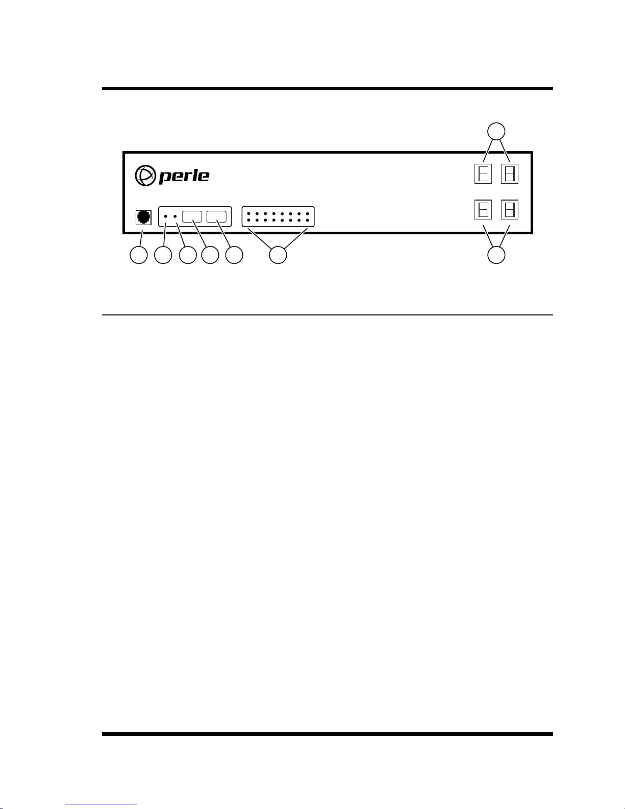
2. Unit Description
7
DEFAULT
ON RDY
SETUP PORT
1 2 3 4
RESET
OUTPUT STATUS
A1 A2 A3 A4 A5 A6 A7 A8
B1 B2 B3 B4 B5 B6 B7 B8
5
Remote Power Switch
6 8
A1 - A4 A5 - A8
Figure 2.1: Front Panel (RPS16 Series Shown)
2.1. RPS Front Panel
As shown in Figure 2.1, the RPS Series Front Panel includes the following components:
1. SetUpPort: An RJ45 RS232 serial port (DCE conguration) used for connection to a
local terminal or external modem, as described in Section 4.3. For a description of the
Setup Port interface, please refer to Appendix B.1.
2. "ON"Indicator: An LED which lights when power is applied to the RPS unit.
3. "RDY"Indicator: (Ready) Flashes if unit is ready to receive commands.
4. DefaultButton: Manually toggles outlets On/Off or resets unit to factory default
parameters as described in Section 2.3.
B5 - B8B1 - B4
5. ResetButton: Reboots and/or resets the RPS to factory defaults as described in
Section 2.3.
Note: All Front Panel Button functions can also be disabled via the System
Parameters menu, as described in Section 5.3.
6. OutputStatusIndicators: LEDs light when corresponding outlet is switched On.
7. BranchACircuitBreakers: Two circuit breakers, which protect Branch A. One circuit
breaker protects outlets A1 through A4, and the other circuit breaker protects outlets A5
through A8.
8. BranchBCircuitBreakers: Same as Item 7 above, except circuit breakers protect
outlets on Branch B.
2-1
Page 11
Unit Description
1
A
B
A1
B1 B2 B3 B4 B5
A 2
A3 A4 A5
2
3
A6
B6 B7
4
A7 A8
ALARM
A
B
B8
5
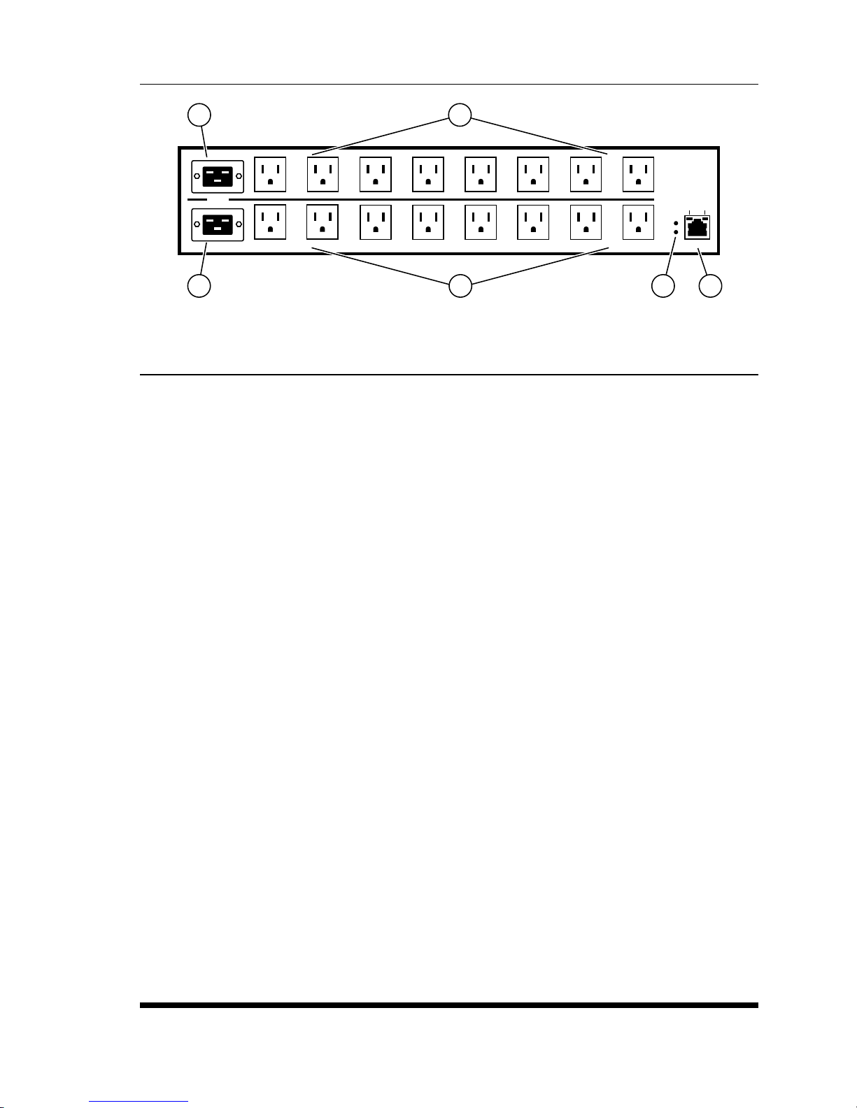
Figure 2.2: Back Panel (Model RPS1630H Shown)
2.2. RPS Series - Back Panel
As shown in Figure 2.2, the RPS Series Back Panel includes the following components:
1. PowerCircuitA-PowerInlet: An IEC320-C20 AC inlet which supplies power to RPS
control functions and the Circuit “A” outlets. Also includes cable keeper (not shown.)
2. PowerCircuitB-PowerInlet: An IEC320-C20 AC inlet which supplies power to RPS
control functions and the Circuit “B” outlets. Also includes cable keeper (not shown.)
ACT
10/100 BaseT
LINK
6
3. PowerCircuitA-SwitchedOutlets: AC Outlets that can be switched On, Off, rebooted
or set to default state in response to user commands:
4. PowerCircuitB-SwitchedOutlets: Same as Item 3 above.
5. AlarmIndicatorLights: For future use.
6. NetworkPort: An RJ45 Ethernet port for connection to your 10/100Base-T, TCP/IP
network. Note that the RPS features a default IP address (192.168.168.168). This allows
you to connect to the unit without rst assigning an IP address. Note that the Network Port
also includes two, small LED indicators for Link and Data Activity. For more information
on Network Port conguration, please refer to Section 5.9.
2-2
Page 12

Unit Description
2.3. Additional Button Functions
The Default and Reset buttons on the RPS front panel can be used to perform the functions
described below:
Notes:
• All Front Panel Button functions can also be disabled via the System Parameters
menu, as described in Section 5.3.
• When the RPS is reset to factory defaults, all user-dened conguration
parameters will be cleared, and the default “super” user account will also be
restored.
1. RebootOperatingSystem:
a) Press and hold the Reset button for ve seconds, and then release it.
b) The RPS will reboot it's operating system; all plugs will be left in their current On/Off
state.
2. SetParameterstoFactoryDefaults:
a) Simultaneously press both the Default button and the Reset button, hold them for ve
seconds, and then release them.
b) All RPS parameters will be reset to their original factory default settings, and the unit
will then reboot. All plugs will be left in their current On/Off state.
3. Toggle/DefaultAllPlugs:
a) Press the Default button, hold it for ve seconds, and then release the Default Button.
b) The RPS will switch all plugs to the Off state. If all plugs are already in the Off state,
then the unit will reset all plugs to their user dened default states.
2-3
Page 13

3. Getting Started
This section describes how to set up the Perle Remote Power Switch (RPS) with your IOLAN
Device Server. If you are using the RPS as a stand-alone, please refer to the remainder of this
user's guide for further information. You can securely manage the power going to any electronic
device through the IOLAN Device Server. For further installation and conguration details,
please see the IOLAN SDS/SCS/STS User's Guide.
3.1. Components
You should receive the following components with your RPS unit:
• Two US Power cords with IEC power connectors (RPS830 and RPS1630H Models Only)
• Quick Start Guide
• CDROM containing the RPS User's Guide and Quick Start Guide
• Rack Mount Brackets
• One CAT5 Cable
• RJ45M to RJ45F Adapter for use with IOLAN models. (Part No. 1100219-10)
• RJ45M to RJ45F Adapter for use with IOLAN C and CM models
(Part No. 1100320-10)
• RJ45F to DB-9F for connecting the RPS SetUp port to the PC COM port
(Part No. 1100300-10)
3.1.1. You Need to Supply
• IOLAN Device Server (If it does not have an RJ45 connector, you will need an adapter.)
• External Power Cords (Europe and UK Only)
3.2. Hardware Installation
The instructions in this section assume that you have already powered up your IOLAN Device
Server according to the Device Server's Quick Start Guide.
3-1
Page 14

Getting Started
3.3. Applying Power to the RPS
Refer to power rating nameplate on the RPS back panel, and then connect the RPS unit to an
appropriate power source. RPS830 and RPS1630H units should be connected to a 100 to 120
VAC power supply, and RPS820 and RPS1620H units should be connected to a 208 to 240 VAC
power supply.
CAUTION: Make certain to review the safety precautions listed in Section 4.1 and
at the beginning of this User's Guide.
Note that RPS units feature two separate AC inputs. Connect power supply cables to the RPS’s
Circuit "A" and Circuit "B" inlets, and then connect the cables to an appropriate power supply.
RPS Series units will support up to 16 Amps maximum per power circuit, for a total load of
32 Amps (de-rated.)
The ON LED should light, and the RDY LED should begin to ash. This indicates that the RPS
is ready to receive commands.
3.4. Connecting the Device Server to the RPS
To securely manage the RPS, congure the Device Server as follows:
1. Set the Line Service (Prole) to Power Management for the line that is connected to the
RPS serial port.
2. Plug the CAT5 cable into the SetUp port on the RPS.
3. Connecting the Adapter to the IOLAN:
(a) ForIOLANModels: Plug the RJ45M to RJ45F Adapter (Part No. 1100219-10) into
the serial port on the IOLAN that will be congued for Power Management. (See
Section 3.5.)
(b) ForIOLANModelCandCM: Plug the RJ45M to RJ45F Adapter (Part No.
1100320-10) into the serial port on the IOLAN C and CM that will be congured for
Power Management. (See Section 3.5.)
4. Connect the CAT5 cable to the Adapter.
3-2
Page 15

Getting Started
3.5. Connecting the Device Server to the RPS
To securely manage the RPS, congure the Device Server as follows:
1. Set the Line Service to Power Management for the line that is connected to the RPS
serial port.
2. Congure the Power Management Settings for the RPS.
See the IOLAN SDS/SCS/STS User’s Guide for information about the settings and how to
actively manage the RPS.
3.6. Configuring the RPS Standalone
To independently manage the RPS, through a PC COM port congure as follows:
NOTE: The default serial port parameters are set as folows: 9600,
RTS/CTS handshaking, 8 data bits, one stop bit and no parity.
1. Plug the RJ45F to DB9F (Part No. 1100300-10) into the COM port on the PC.
2. Connect the CAT5 cable to this adapter and the RJ45 SetUp port on the RPS.
3. Start your communication program on your PC (set serial port parameters as described
above.)
4. Press [Enter]
5. The RPS will return the RPS> command prompt.
6. Type /h and press [Enter] to view the command menu.
Please refer to the remainder of this User's Guide for instructions regarding other methods to
connect to the RPS.
3-3
Page 16

4. Hardware Installation
This section provides further details regarding installation the RPS unit.
4.1. Power Supply Connection
Use the supplied power cords to connect the RPS to an appropriate power supply. RPS830 and
RPS1630H units should be connected to a 100 to 120 VAC Power Supply, and RPS820 and
RPS1620H units should be connected to a 208 to 240 VAC power supply.
CAUTIONS:
• This device should only be operated with the type of power source indicated
on the instrument nameplate. If you are not sure of the type of power service
available, please contact your local power company.
• Reliable earthing (grounding) of this unit must be maintained. Particular
attention should be given to supply connections when connecting to power strips,
rather than directly to the branch circuit.
• Check nameplate ratings to ensure that there is no overloading of supply circuits
that could have an effect on overcurrent protection and supply wiring.
4.1.1. Installing the Cable Keepers
The RPS includes cable keepers, which are designed to prevent the power supply cables from
being accidentally disconnected from the unit.
• RPS1620HandRPS1630H: Sixteen-plug units include pre-installed cable keepers.
When attaching the power supply cables to the unit, rst swing the cable keepers out of the
way, then plug the power cables securely into the power inputs. When the cables are in
place, snap the cable keepers over each plug to secure the cables to the unit.
• RPS820andRPS830: The cable keeper for eight-plug units must be installed by the user.
First make certain that both of the RPS's two power cables are disconnected from your
power supply. Next, loosen (but do not remove) the retaining screws located adjacent to
the power inlets. Connect the power supply cables to the RPS power inlets, then slip the
cable keepers under each supply cable so the notches at the top of the keeper line up with
each cable, and the two slots on the bottom of the keeper slide under the loosened retaining
screws. Tighten the retaining screws to secure the cable keeper to the unit, make certain
that the cables are secure, and then connect the cables to your power supply.
4-1
Page 17

Hardware Installation
4.2. Connection to Switched Outlets
Connect the power cord from each device that you wish to control, to a Switched AC Outlet
on the RPS unit. Note that when power is applied to the RPS in the default state, the Switched
Outlets will all initially be switched "ON".
RPS830 and RPS1630H units are designed for 100 to 120 VAC power control; Power Circuit "A"
can switch up to 16 Amps, and Power Circuit "B" can also switch up to 16 Amps, providing a
maximum total load of 32 Amps for the unit (de-rated.)
RPS820 and RPS1620H units are designed for 208 to 240 VAC power control; Power Circuit "A"
can switch up to 16 Amps, and Power Circuit "B" can also switch up to 16 Amps, providing a
maximum total load of 32 Amps for the unit (de-rated.)
4.3. SetUp Port Connection
The Setup port is a female RS232C RJ45 (Cisco pinout) connector wired in a DTE conguration
similar to an AT computer. In the default state, the SetUp port is congured for 9600 bps, no
parity, 8 data bits, 1 stop bit. The SetUp Port can be connected to either an external modem or a
local PC, but not both items at the same time. Appendix B.1 describes the SetUp Port interface.
4.3.1. Connecting a Local PC
When connecting the SetUp Port to a Local PC, note that the port uses a DTE conguration.
After the Local PC has been connected, make certain to set the Serial Port Mode to "Normal" as
described in Section 5.8. In order to connect the COM port on your PC to the RPS unit you will
need to connect the RJ45F to DB9F adapter ( part#1100300-10) into the COM port on the PC.
See Section 3.6 for more details.
4.3.2. Connecting an External Modem
When connecting directly to an external modem, use a standard AT Style to Modem cable. Make
certain that the modem is initialized to the same default communications parameters as the RPS
SetUp Port. Next, refer to Section 5.8 and set the Serial Port Mode to "Modem". If necessary,
you may also wish to redene the Modem initialization command at this point as described in
Section 5.8. Please refer to the modem user’s guide for more information.
4-2
Page 18

Hardware Installation
4.4. Connecting the Network Cable
The Network Port is an RJ45 Ethernet jack, for connection to a TCP/IP network. Connect
your 10/100Base-T cable to the Network Port. Note that the RPS includes a default IP address
(192.168.168.168) and a default subnet mask (255.255.255.0.) When installing the RPS in a
working network environment, it is recommended to dene network parameters as described in
Section 5.9.
This completes the RPS installation instructions. Please proceed to the next Section for
instructions regarding unit conguration.
4-3
Page 19

5. Basic Configuration
This section describes the basic conguration procedure for all RPS units. This procedure can be
used to recongure the RPS unit in the event that you intend to use it as a stand-alone unit.
5.1. Communicating with the RPS Unit
In order to congure the RPS, you must rst connect to the unit, and access command mode.
Note that, the RPS offers two separate conguration interfaces; the Web Browser Interface and
the Text Interface.
In addition, the RPS also offers three different methods for accessing command mode; via
network, via external modem, or via local console. The Web Browser interface is only available
via network, and the Text Interface is available via Telnet, modem or local PC.
5.1.1. The Text Interface
The Text Interface consists of a series of simple ASCII text menus, which allow you to set options
and dene parameters by entering the number for the desired option using your keyboard, and
then typing in the value for that option.
You can to use the Text Interface to communicate with the RPS via local PC or Telnet connection.
You can also use the Text Interface to access command mode via an external modem installed at
the RPS serial Setup Port.
In order to use the Text Interface, your installation must include:
• AccessviaNetwork: The RPS must be connected to your TCP/IP Network, and your PC
must include a communications program (such as HyperTerminal.)
• AccessviaModem: An external modem must be installed at the RPS RS232 Setup
Port (see Section 4.3.2), a phone line must be connected to the external modem, and the
Setup Port must be congured for Modem Mode. In addition, your PC must include a
communications program.
• AccessviaLocalPC: Your PC must be physically connected to the RPS RS232 Setup
Port as described in Section 4.3.1, the RPS Setup Port must be congured for Normal
Mode, and your PC must include a communications program.
5-1
Page 20

Basic Configuration
To access command mode via the Text Interface, proceed as follows:
1. Contact the RPS Unit:
a) ViaLocalPC: Start your communications program and press [Enter].
b) ViaNetwork: The RPS includes a default IP address (192.168.168.168) and a default
subnet mask (255.255.255.0.) This allows you to contact the unit from any network
node on the same subnet, without rst assigning an IP Address to the unit. For more
information, please refer to Section 5.9. Start your Telnet Client, and then Telnet to
the RPS IP Address.
c) ViaModem: Use your communications program to dial the number for the external
modem which you have connected to the RPS Setup Port.
2. If a valid username and password are entered, the RPS will display a welcome screen.
5.1.2. The Web Browser Interface
The Web Browser Interface consists of a series of web forms, which can be used to select
conguration parameters and perform reboot operations, by clicking on buttons and/or entering
text into designated elds.
1. Start your JavaScript enabled Web Browser, key the RPS IP address
(default = 192.168.168.168) into the web browser’s address bar, and press [Enter].
2. A welcome screen will be displayed.
5-2
Page 21

Basic Configuration
5.2. Configuration Menus
Although the Web Browser Interface and Text Interface provide two separate means for selecting
parameters, both interfaces allow access to the same set of basic parameters, and parameters
selected via one interface will also be applied to the other. To access the conguration menus,
proceed as follows:
• TextInterface: Refer to the Help Screen (/H) and then enter the appropriate command to
access the desired menu. When the conguration menu appears, key in the number for the
parameter you wish to dene, and follow the instructions in the resulting submenu.
• WebBrowserInterface: Use the links and y-out menus on the left hand of the screen to
access the desired conguration menu. To change parameters, click in the desired eld and
key in the new value or select a value from the pull-down menu. To apply newly selected
parameters, click on the "Change Parameters" button at the bottom of the menu or the
"Set" button next to the eld.
The following sections describe options and parameters that can be accessed via each of the
conguration menus. Please note that essentially the same set of parameters and options are
available to both the Web Browser Interface and Text Interface.
Notes:
• Conguration menus are not available when you have logged into command
mode via a SuperUser, User or ViewOnly level password. SuperUser accounts
are able to view conguration menus, but are not allowed to change parameters.
• When dening parameters via the Text Interface, make certain to press the [Esc]
key to completely exit from the conguration menu and save newly dened
parameters. When parameters are dened via the Text Interface, newly dened
parameters will not be saved until the "Saving Conguration" message has been
displayed and the cursor returns to the command prompt.
5-3
Page 22

Basic Configuration
5.3. Defining System Parameters
The System Parameters menus are used to dene the Site ID Message, set the system clock and
calendar, and congure the Invalid Access Lockout feature and Callback feature.
To access the System Parameters menu via the Text Interface, type /F and press [Enter]. To
access the System Parameters menu via the Web Browser Interface, place the cursor over the
"General Parameters" link, wait for the yout menu to appear and then click on the "System
Parameters" link. The System Parameters Menus are used to dene the following:
• UserDirectory: This function is used to view, add, modify and delete user accounts and
passwords. As discussed in Section 5.4 and Section 5.5, the User Directory allows you to
set the security level for each account as well as determine which plugs each account will
be allowed to control.
Note: The "User Directory" option does not appear in the Web Browser Interface’s
System Parameters menu, and is instead, accessed via the "User Conguration" link
on the left hand side of the menu.
• SiteID: A text eld, generally used to note the installation site or name for the RPS unit.
(Default = undened.)
• RealTimeClock: This prompt provides access to the Real Time Clock menu, which is
used to set the clock and calendar, and to enable and congure the NTP (Network Time
Protocol) feature as described in Section 5.3.1.
Note: The "Real Time Clock" option does not appear in the Web Browser Interface’s
System Parameters menu, and is instead, accessed via the "Real Time Clock" link in
the General Parameters y-out menu.
• InvalidAccessLockout: If desired, this feature can be used to temporarily disable SetUp
Port access, Telnet access and/or Web access to the RPS command mode after a user
specied number of unsuccessful login attempts are made. For more information, please
refer to Section 5.3.2. (Default = Off.)
Note: The "Invalid Access Lockout" item does not appear in the Web Browser
Interface’s System Parameters menu, and is instead, accessed via the link in the
General Parameters y-out menu.
• TemperatureFormat: Determines whether the temperature is displayed as Fahrenheit or
Celsius. (Default = Fahrenheit.)
• TemperatureCalibration: Used to calibrate the unit's internal temperature sensing
abilities. To calibrate the temperature, place a thermometer inside your equipment rack,
in a location that usually experiences the highest temperature. After a few minutes, take
a reading from the thermometer, and then key the reading into the conguration menu. In
the Web Browser Interface, the temperature is entered at the System Parameters menu,
in the Temperature Calibration eld; in the Text Interface, the temperature is entered in a
submenu of the System Parameters menu, accessed via the Temperature Calibration item.
(Default = undened.)
5-4
Page 23

Basic Configuration
• LogConguration: Congures the Audit Log, Alarm Log, Temperature Log and Current
Metering Log. For more information on the RPS's event logging functions, please refer
to Section 5.3.3. (Defaults: Audit Log = On without Syslog, Alarm Log = On without
Syslog, Temperature Log = On, Current Metering Log = On.)
Notes:
• The Audit Log will create a record of all connection/disconnection and login/
logout activity at the RPS unit.
• The Alarm Log is not used at this time and is reserved for future use.
• The Temperature Log will create a record of ambient rack temperature
over time.
• CallbackSecurity: Enables / congures the Callback Security Function as described
in Section 5.3.4. In order for this feature to function, a Callback number must also be
dened for each desired user account as described in Section 5.5. (Default = On, Callback,
Without Password Prompt.)
Notes:
• In the Text Interface, Callback Security Parameters are dened via a submenu of
the Systems Parameters Menu, which is accessed via the Callback Security item.
• In the Web Browser Interface, Callback Security Parameters are dened via the
"Callback Security" link in the General Parameters y-out menu.
• FrontPanelButtons: This item can be used to disable all front panel button functions.
(Default = On.)
• ModemPhoneNumber: When an optional external modem is connected to the RPS
Setup Port, the Modem Phone Number parameter can be used to denote the phone number
for the external modem. (Default = undened.)
• ScriptingOptions: Provides access to a submenu that is used to congure the Command
Conrmation, Automated Mode, Command Prompt and RPS Mode parameters as
described in Section 5.3.5.
Note: In the Text Interface, the Scripting Options submenu is accessed via item 12.
To access the Scripting Options parameters via the Web Browser Interface, place the
cursor over the "General Parameters" link, wait for the yout menu to appear, then
click on the "Scripting Options" link.
• SerialNumber: Allows the serial number for the RPS unit to be saved and displayed.
When this parameter is dened, the serial number can be displayed via the Product Status
screen in the Web Browser or by invoking the /J* command in the Text Interface. Since
the serial number plate on the RPS unit is not always easily accessible after installation,
it is often helpful to dene the serial number here in order to simplify the process of
determining the serial number later. (Default = undened.)
5-5
Page 24

Basic Configuration
5.3.1. The Real Time Clock and Calendar
The Real Time Clock menu is used to set the RPS internal clock and calendar. The conguration
menu for the Real Time Clock offers the following options:
• Date: Sets the Month, Date, Year and day of the week for the real-time clock/calendar.
• Time: Sets the Hour, Minute and Second for the RPS real time clock/calendar. Key in the
time using the 24-hour (military) format.
• TimeZone: Sets the time zone, relative to Greenwich Mean Time. Note that the Time
Zone setting will function differently, depending upon whether or not the NTP feature is
enabled and properly congured. (Default = GMT (No DST).)
NTPEnabled: The Time Zone setting is used to adjust the Greenwich Mean Time
value (received from the NTP server) in order to determine the precise local time for
the selected time zone.
NTPDisabled: If NTP is disabled, or if the RPS is not able to access the NTP server,
then status screens and activity logs will list the selected Time Zone and current Real
Time Clock value, but will not apply the correction factor to the displayed Real Time
Clock value.
• NTPEnable: When enabled, the RPS will contact an NTP server (dened via the NTP
Address prompts) once a day, and update its clock based on the NTP server time and
selected Time Zone. (Default = Off.)
Notes:
• The RPS will also contact the NTP server and update the time whenever you
change NTP parameters.
• To cause RPS to immediately contact the NTP server at any time, make certain
that the NTP feature is enabled and congured, then type /F and press [Enter].
When the System Parameters menu appears, press [Esc]. The RPS will save
parameters and then attempt to contact the server, as specied by currently
dened NTP parameters.
• PrimaryNTPAddress: Denes the IP address or domain name (up to 64 characters long)
for the primary NTP server. (Default = undened.)
Note: In order to use domain names for web addresses, DNS parameters must rst
be dened as described in Section 5.9.5.
• SecondaryNTPAddress: Denes the IP address or domain name (up to 64 characters
long) for the secondary, fallback NTP Server. (Default = undened.)
Note: In order to use domain names for web addresses, DNS parameters must be
dened as described in Section 5.9.5.
5-6
Page 25

Basic Configuration
• NTPTimeout: The amount of time in seconds, that will elapse between each attempt to
contact the NTP server. When the initial attempt is unsuccessful, the RPS will retry the
connection four times. If neither the primary nor secondary NTP server responds, the RPS
will wait 24 hours before attempting to contact the NTP server again.
(Default = 3 Seconds.)
• TestNTPServers: (Text Interface Only) Allows you to ping the IP addresses or domain
names dened via the Primary and Secondary NTP Address prompts, or to ping a new
address or domain dened via the Test NTP Servers submenu in order to check that a valid
IP address or domain name has been entered.
Note: In order for the Test NTP Servers feature to function, your network and/or
rewall must be congured to allow ping commands.
5.3.2. The Invalid Access Lockout Feature
When properly congured and enabled, the Invalid Access Lockout feature can watch all login
attempts made via Telnet connection, web browser or the serial SetUp Port. If the counter for any
of these exceeds the user-dened threshold for maximum invalid attempts, then the corresponding
port or protocol will be automatically disabled for the length of time specied by the Lockout
Duration parameter.
When Invalid Access Attempt monitoring is enabled for the serial SetUp Port, the RPS will
count invalid access attempts at the serial SetUp Port. If the number of invalid access attempts
exceeds the dened Lockout Attempts trigger value, the RPS will lock the serial SetUp Port for
the dened Lockout Duration period. When Invalid Access Attempt monitoring for Telnet or Web
are selected, a lockout will be triggered when the number of invalid access attempts during the
dened Lockout Duration period exceeds the dened Hit Count for the protocol. For example,
if the Telnet Hit Count is set at 10 and the Telnet Lockout Duration period is set at 120 seconds,
then if over 10 invalid access attempts are detected within 120 seconds, the RPS will then lock
out the MAC address that generated the excessive attempts for 120 seconds.
Note that when an Invalid Access Lockout occurs, you can either wait for the Lockout Duration
period to elapse (after which, the RPS will automatically reactivate the port or protocol), or you
can issue the /UL command (type /UL and press [Enter]) via the Text Interface to instantly
unlock all RPS logical network ports and communication protocols.
Note: If the Network Port has been locked by the Invalid Access Lockout feature, it
will still respond to the ping command (providing that the ping command has not been
disabled at the Network Port.)
5-7
Page 26

Basic Configuration
The Invalid Access Lockout conguration menus allow you to select the following parameters:
• SerialPortProtection: Enables/Disables the Invalid Access Lockout function for the
serial SetUp Port and selects lockout parameters. When this item is enabled and excessive
Invalid Access attempts are detected at the SetUp Port, the SetUp Port will be locked until
the user-dened Lockout Duration period elapses, or until the /UL command is issued.
• SerialPortProtection: Enables/Disables the Invalid Access Lockout feature for the
SetUp Port. (Default = Off.)
• LockoutAttempts: The number of invalid attempts that must occur in order to
trigger the Invalid Access Lockout feature at the SetUp Port. (Default = 9.)
• LockoutDuration: This option selects the length of time that the serial SetUp Port
will remain locked when Invalid Access Lockout occurs. If the duration is set at
"Innite", then ports will remained locked until the /UL command is issued.
(Default = 30 Minutes.)
• TelnetProtection: Enables/Disables and congures the Invalid Access function for Telnet
connections. When this item is enabled and excessive Invalid Access Attempts via Telnet
are detected, then the RPS will lock out the offending MAC address for the user-dened
Telnet Lockout Duration Period or until the /UL command is issued. Note that for Telnet
protection, the lockout trigger is a function of the Telnet Hit Count parameter and the
Telnet Lockout Duration Parameter.
• LockoutEnable: Enables/Disables Invalid Access Lockout protection for Telnet
connections. (Default = Off.)
• TelnetHitCount: The number of invalid attempts that must occur during the length
of time specied by the Telnet Lockout Duration period in order to trigger the Invalid
Access Lockout feature for the Telnet protocol. For example, if the Telnet Hit Count
parameter is set to 10 and the Telnet Lockout Duration parameter is set to 30 minutes,
then the RPS will lock out the offending MAC address for 30 minutes when over 10
invalid access attempts occur during any 30 minute long period. (Default = 5.)
• TelnetLockoutDuration: This option selects both the length of time that a Telnet
Lockout will remain in effect and also the time period over which invalid access
attempts will be counted. When a Telnet Lockout occurs, the offending MAC address
will be prevented from establishing a Telnet connection to the RPS for the dened
Telnet Lockout Duration period. (Default = 120 Seconds.)
5-8
Page 27

Basic Configuration
• WebProtection: Enables/Disables and congures the Invalid Access function for Web
connections. When this item is enabled and excessive Invalid Access Attempts via Web
are detected, then the RPS will lock out the offending MAC address for the user-dened
Web Lockout Duration Period or until the /UL command is issued. Note that for Web
protection, the lockout trigger is a function of the Web Hit Count parameter and the Web
Lockout Duration Parameter.
• LockoutEnable: Enables/Disables Invalid Access Lockout protection for web
connections. (Default = Off.)
• WebHitCount: The number of invalid attempts that must occur during the length
of time specied by the Web Lockout Duration period in order to trigger the Invalid
Access Lockout feature for Web access. For example, if the Web Hit Count parameter
is set to 10 and the Web Lockout Duration parameter is set to 30 minutes, then the
RPS will lock out the offending MAC address for 30 minutes when over 10 invalid
access attempts occur during any 30 minute long period. (Default = 20.)
• WebLockoutDuration: This option selects both the length of time that a Web
Lockout will remain in effect and also the time period over which invalid access
attempts will be counted. When a Web Lockout occurs, the offending MAC address
will be prevented from establishing a Web connection to the RPS for the dened
Telnet Lockout Duration period. (Default = 60 Seconds.)
5.3.3. Log Configuration
This feature allows you to create records of command activity and temperature readings for the
RPS unit. The Log features are enabled and congured via the System Parameters Menus.
• AuditLog: Creates a record of all power switching at the RPS unit, including reboots.
Each Log record includes a description of the activity that caused the power switching, the
username for the account that initiated the power switching or reboot and the time and date
that the power switching or reboot occurred. In addition to power switching activity, the
Audit Log will also include login/logout activity for each user account.
• AlarmLog: This feature is not used at this time and is reserved for future rmware
upgrades.
• TemperatureLog: The Temperature Log provides a record of temperature levels over
time at the RPS unit. Each Log record will include the time and date, and the temperature
reading.
5-9
Page 28

Basic Configuration
5.3.3.1. AuditLogConfigurationOptions
The Log Conguration options in the System Parameters menu allows you to enable/disable and
congure the Audit Log. The Audit Log offers the following parameters:
• Off: The Log is disabled, and command activity will not be logged. (Default Setting.)
• On-WithSyslog: The Log is enabled, and power switching and user activity will be
logged. The RPS will generate a Syslog Message every time a Log record is created.
• On-WithoutSyslog: The Log is enabled, and power switching, login/logout activity will
be recorded, but the RPS will not generate a Syslog Message every time a Log record is
created.
Notes:
• In order for the Audit Log to generate Syslog Messages, Syslog Parameters must
rst be dened as described in Section 8.
• The Audit Log will truncate usernames that are longer than 22 characters, and
display two dots (..) in place of the remaining characters.
5.3.3.2. Reading,DownloadingandErasingLogs
To read or download the status logs, proceed as follows:
• TextInterface: Type /L and press [Enter] to access the Display Log menu. Select
the desired option, key in the appropriate number, press [Enter] and then follow the
instructions in the "Display Logs" submenu. In the text interface, The Display Logs menu
is used to download or display the Audit Log and Temperature Log.
• WebBrowserInterface: Move the cursor over the "Current Metering," "Power
Metering" or "Logs" link. When the yout menu appears, click on the desired option and
then follow the instructions in the resulting submenu.
To erase logged data, proceed as follows:
• AuditLog: The Audit Log can be displayed or downloaded via either Text Interface or
Web Browser Interface. When the Audit Log is displayed via the Text Interface, the RPS
will also offer the option to erase Audit Log data.
• TemperatureLog: The Temperature Log can be displayed or downloaded via either Text
Interface or Web Browser Interface. When the Temperature Log is displayed via Text
Interface, the RPS will also offer the option to erase Temperature Log data.
5-10
Page 29

Basic Configuration
5.3.4. Callback Security
The Callback function provides an additional layer of security when callers attempt to access
command mode via modem. When this function is properly congured, modem users will not be
granted immediate access to command mode; instead, the unit will disconnect, and dial a userdened number before allowing access via that number. If desired, users may also be required to
re-enter the password after the RPS dials back.
In order for Callback Security to function properly, you must rst enable and congure the feature
via the System Parameters menu as described in this section, and then dene a callback number
for each desired user account as described in Section 5.5. To access the Callback Security menu
via the Text Interface, type /F and press [Enter]and then select the Callback Security option.
To access the Callback Security menu via the Web Browser Interface, place the cursor over the
General Parameters link, wait for the yout menu to appear, and then Click on the "Callback
Security" link.
Note: RPS Password features will not function unless at least one user account has
been dened, and the RPS Mode feature is disabled (See Section 5.3.5.)
In both the Text Interface and Web Browser Interface, the Callback Security Menu offers the
following options:
• CallbackEnable: This prompt offers ve different conguration options for the Callback
Security feature: (Default = On - Callback (Without Password Prompt.)
Off: All Callback Security is disabled.
On-Callback(WithoutPasswordPrompt): Callbacks will be performed for user
accounts that include a Callback Number, and the login prompt will not be displayed
when the user’s modem answers. If the account does not include a Callback Number,
that user will be granted immediate access.
On-Callback(WithPasswordPrompt): Callbacks will be performed for user
accounts that include a Callback Number, and the login prompt will be displayed when
the user’s modem answers (accounts that include a Callback Number will be required
to re-enter their username/password when their modem answers.) If the account does
not include a Callback Number, then that user will be granted immediate access.
On-CallbackONLY(WithoutPasswordPrompt): Callbacks will be performed
for user accounts that include a Callback Number, and the username/password prompt
will not be displayed when the user’s modem answers. Accounts that do not include a
Callback Number will not be able to access command mode via modem.
On-CallbackONLY(WithPasswordPrompt): Callbacks will be performed for
accounts that include a Callback Number, and the username/password prompt will
be displayed when the user’s modem answers (users will be required to re-enter their
username/password when their modem answers.) Accounts that do not include a
Callback Number will not be able to access command mode via modem.
5-11
Page 30

Basic Configuration
• CallbackAttempts: The number of times that the RPS will attempt to contact the
Callback number. (Default = 3 attempts.)
• CallbackDelay: The amount of time that the RPS will wait between Callback attempts.
(Default = 30 seconds.)
Notes:
• After conguring and enabling Callback Security, you must then dene a callback
phone number for each desired user account (as described in Section 5.5) in
order for this feature to function properly.
• When using the "On - Callback (With Password Prompt)" option, it is important
to remember that accounts that do not include a callback number will be allowed
to access command mode without callback verication.
5.3.5. Scripting Options
The Scripting Options submenu provides access to parameters that are used to set up the RPS unit
for running various scripts.
Notes:
• To access Scripting Options parameters via the Text Interface, rst type /F and
press [Enter]to display the System Parameters Menu, then key in the number for
the Scripting Options item and press [Enter].
• To access the Scripting Options parameters via the Web Browser Interface, place
the cursor over the "General Parameters" link, wait for the yout menu to appear,
then click on the "Scripting Options" link.
The Scripting Options menu allows the following parameters to be dened:
• CommandConrmation: Enables/Disables the Command Conrmation feature. When
enabled, a "Sure" prompt will be displayed before power switching and reboot commands
are executed. When disabled, commands will be executed without further prompting.
(Default = On.)
• AutomatedMode: When enabled, the RPS will execute switching and reboot commands
without displaying a conrmation prompt, status screen or conrmation messages. For
more information, please refer to Section 5.3.5.1 or Section 7.3. (Default = Off.)
Notes:
• When Automated Mode is enabled, security functions are suppressed, and users
are able to access conguration menus and control plugs without entering
a password. If security is a concern and Automated Mode is required, it is
recommended to use the IP Security feature (Section 5.9.3) to restrict access.
• RPS Password features will not function unless at least one user account has been
dened, and the RPS Mode feature is disabled (See Section 5.3.5.)
5-12
Page 31

Basic Configuration
• CommandPrompt: Allows the Text Interface command prompt to be set to either MPC,
VMR, RPS, CCM or NPS. (Default = RPS.)
• RPSMode: This parameter sets up the RPS for use with command scripts. When the
RPS Mode is enabled, the "RPS" command prompt will be displayed in the Text Mode,
User Accounts will not allow denition of a Username, and the username and password
prompts will be not displayed when logging into the unit via Text Interface.
(Default = On.)
• The "RPS" command prompt will be displayed in the Text Mode.
• Providing that no Administrator level user accounts have been dened, the RPS will
not display the username or password prompts upon login to command mode.
• If one or more Administrator level user accounts have been dened, then the RPS will
only display the password prompt upon login to command mode. If all Administrator
level user accounts (aside from the default "super" account) are deleted, then the RPS
will return to the status where no username or password prompts are displayed upon
login to command mode.
5-13
Page 32

Basic Configuration
5.3.5.1. AutomatedMode
The Automated Mode allows the RPS to execute switching and reboot commands, without
displaying menus or generating response messages. Automated Mode is designed to allow the
RPS to be controlled by a device which can generate commands to control power switching
functions without human intervention.
When Automated Mode is enabled, power switching and reboot commands are executed
without a conrmation prompt and without command response messages; the only reply to these
commands is the command prompt, which is re-displayed when each command is completed.
Although Automated Mode can be enabled via either the Web Browser Interface or Text Interface,
Automated Mode is designed primarily for users who wish to send ASCII commands to the RPS
without operator intervention, and therefore does not specically apply to the Web Browser
Interface. When Automated Mode is enabled, the Web Browser Interface can still be used to
invoke switching and reboot commands.
Notes:
• When the Automated Mode is enabled, password prompts will not be displayed
at login, and you will be able to access Administrator Level command functions
(including the conguration menus) and control plugs without entering a
password.
• If you need to enable the Automated Mode, but want to restrict network access to
conguration menus, it is strongly recommended to enable and congure the IP
Security Function as described in Section 5.9.3.
To enable/disable the Automated Mode, go to the System Parameters menu (see Section 5.3,)
access the Scripting Options submenu and then set the “Automated Mode” option to “On”. When
Automated Mode is enabled, RPS functions will change as follows:
1. AllPasswordSecuritySuppressed: When a user attempts to access command mode, the
password prompt will not be displayed at either the Setup Port or Network Port. Unless
specically restricted by the IP Security Function, all users will be allowed to access both
switching and conguration functions, and all commands will be immediately accepted
without the requirement to enter a password.
2. StatusScreenSuppressed: The plug status screen will not be displayed after commands
are successfully executed. Note however, that the /S command can still be invoked to
display the status screen as needed.
3. “Sure?”PromptSuppressed: All commands are executed without prompting for user
conrmation.
4. ErrorMessagesSuppressed: Most error messages will be suppressed. Note however,
that an error message will still be generated if commands are invoked using invalid formats
or arguments.
All other status display and conguration commands will still function as normal.
5-14
Page 33

Basic Configuration
5.4. User Accounts
If desired, the RPS can be congured to prompt users to enter a password before being allowed
to access command mode. The password entered at login can then be used to determine which
outlet(s) each user will be allowed to control and what type of commands the user will be allowed
to invoke. Each password and associated access rights are dened within a "user account."
The RPS allows up to 128 user accounts; each account includes a username, password, security
level, plug access rights, service access rights and an optional callback number.
Notes:
• In order for the RPS to display the password prompt, at least one user account
must be dened via the User Directory function.
• In order to display both a password prompt and username prompt, the RPS mode
must be disabled as described in Section 5.3.5.
5.4.1. Command Access Levels
In order to restrict access to important command functions, the RPS allows you to set the
command access level for each user account. The RPS offers four access levels: Administrator,
SuperUser, User and View Only. Command privileges for each account are set using the "Access
Level" parameter in the Add User or Modify User menus.
Each access level grants permission to use a different selection of commands; lower access levels
are restricted from invoking conguration commands, while Administrators are granted access to
all commands. The four different access levels are listed below:
• Administrator: Administrators are allowed to invoke all conguration and power
switching commands, can view all status screens, and can always direct switching
commands to all RPS switched outlets .
• SuperUser: SuperUsers are allowed to invoke all power switching commands and view
all status screens. SuperUsers can view conguration menus, but are not allowed to
change conguration parameters. SuperUsers are granted access to all RPS outlets.
• User: Users are allowed to invoke power switching commands and view all status
screens, but can only apply commands to outlets that they are specically granted access
to. In addition, Users are not allowed to view conguration menus or change conguration
parameters.
• ViewOnly: Accounts with ViewOnly access, are allowed to view Status Menus, but are
not allowed to invoke switching commands, and cannot view conguration menus or
change parameters. ViewOnly accounts can display the Plug Status screen, but can only
view the status of plugs that are allowed by the account.
Section 11.2 summarizes command access for all four access levels.
5-15
Page 34

Basic Configuration
In the default state, the RPS includes one predened account that provides access to
Administrator commands and allows control of all RPS switched power outlets. The default
username for this account is "super" (lowercase, no quotation marks), and the password for the
account is also "super".
Notes:
• If the RPS will be used in Non-RPS mode and security is a concern, it is
recommended that when initially setting up the unit, a new user account with
Administrator access should be created, and the "super" account should then
be deleted.
• If the RPS is reset to default parameters, all user accounts will be cleared, and
the default "super" account will be restored.
5.4.2. Plug Access
Each account can be granted access to a different selection of power outlets (plugs) and plug
groups. When accounts are created, the Plug Access parameter and the Plug Group Access
parameter in the Add User menu or Modify User menu are used to grant or deny access to each
plug or plug group. In addition, each access level also restricts the plugs and plug groups that the
account will be allowed to access:
• Administrator: Administrator level accounts are always allowed to control all plugs and
plug groups. Plug access cannot be disabled for Administrator level accounts.
• SuperUser: SuperUser accounts allow access to all plugs and plug groups. Port access
cannot be disabled for SuperUser accounts.
• User: User level accounts are only allowed to issue switching commands to the plugs and
plug groups that have been specically permitted via the "Plug Access" parameter in the
Add User and Modify User menus.
• ViewOnly: ViewOnly level accounts are not allowed to issue switching commands.
ViewOnly accounts can display the On/Off state of plugs and plug groups, but are limited
to the plugs and plug groups specied by the account.
5.4.3. Port Access
The Port Access parameter is used to grant or deny access to the RPS RJ45 Setup Port. Normally,
the Setup port is used for connection to a local control device or an external modem.
The command access level will also determine which ports the account will be allowed to access,
as summarized below:
• AdministratorandSuperUser: Accounts with Administrator or SuperUser level
command access are always allowed to connect to the Setup Port. Port access cannot be
disabled for Administrator and SuperUser level accounts.
• User: User level accounts are only allowed to connect to the Setup Port when port access
has been specically enabled for the account.
• ViewOnly: Accounts with ViewOnly access are not allowed to create connections to the
Setup Port.
5-16
Page 35

Basic Configuration
5.5. Managing User Accounts
The User Directory function is employed to create new accounts, display parameters for existing
accounts, modify accounts and delete accounts. Up to 128 different user accounts can be created.
The "User Directory" function is only available when you have logged into command mode using
an account that permits Administrator commands.
In both the Text Interface and the Web Browser Interface, the User Directory menu offers the
following functions:
• ViewUserDirectory: Displays currently dened parameters for any RPS user account as
described in Section 5.5.1.
• AddUsername: Creates new user accounts and allows you to assign a username,
password, command level, plug access plug group access, service access and callback
number, as described in Section 5.5.2.
• ModifyUserDirectory: This option is used to edit or change account information, as
described in Section 5.5.3.
• DeleteUser: Clears user accounts, as described in Section 5.5.4.
Note: After you have nished selecting or editing user account parameters, make
certain to save the new account information before proceeding. In the Web Browser
Interface, click on the "Add User" button to save parameters; in the Text Interface,
press the [Esc] key several times until the RPS displays the "Saving Conguration"
message and the cursor returns to the command prompt.
5.5.1. Viewing User Accounts
The "View User Directory" option allows you to view details about each account. The View User
option will not display actual passwords, and instead, the password eld will read "dened". The
View User Accounts function is only available when you have accessed command mode using a
password that permits Administrator Level commands.
5.5.2. Adding User Accounts
The "Add Username" option allows you to create new accounts. Note that the Add User function
is only available when you have accessed command mode using a password that permits
Administrator Level commands. The Add User Menu can dene the following parameters for
each new account:
• Username: Up to 32 characters long, and cannot include non-printable characters.
Duplicate usernames are not allowed. (Default = undened.)
Note: The username parameter is only available when the RPS mode has been
disabled as described in Section 5.3.5.
• Password: Five to sixteen characters long, and cannot include non-printable characters.
Note that passwords are case sensitive. (Default = undened.)
5-17
Page 36

Basic Configuration
• AccessLevel: Determines which commands this account will be allowed to access. This
option can set the access level for this account to "Administrator", "SuperUser", "User"
or "ViewOnly." For more information on Command Access Levels, please refer to
Section 5.4.1 and Section 11.2. (Default = User.)
• PortAccess: Determines whether or not the account will be allowed to connect to the
serial Setup Port. (Defaults; Administrator and SuperUser = Always Enabled, User =
Disabled.)
Note: ViewOnly level accounts cannot be granted access to the Setup Port.
• PlugAccess: Determines which outlet(s) this account will be allowed to control.
(Defaults; Administrator and SuperUser = All Plugs On, User = All Plugs Off,
ViewOnly = All Plugs Off.)
Notes:
• Administrator and SuperUser level accounts always have access to all plugs.
• User level accounts will only have access to the plugs that are dened via the
"Plug Access" parameter.
• ViewOnly accounts are allowed to display the Plug Status Screen, but are limited
to the plugs specied by the account. ViewOnly accounts are not allowed to
invoke switching and reboot commands.
• PlugGroupAccess: Determines which plug groups this account will be allowed to
control. For more information on Plug Groups, please refer to Section 5.6.
(Defaults; Administrator and SuperUser = All Plug Groups On, User = All Plug Groups
Off, ViewOnly = All Plug Groups Off.)
Notes:
• In order to use this feature, Plug Groups must rst be dened as described in
Section 5.6.
• Administrator and SuperUser level accounts will always have access to all plug
groups.
• User Level accounts will only have access to the plug groups that are dened via
the Plug Group Access parameter.
• ViewOnly accounts are allowed to display the On/Off status of plug groups via the
Plug Status Screen, but are limited to the plug groups specied by the account.
ViewOnly accounts are not allowed to invoke switching and reboot commands.
• ServiceAccess: Determines whether this account will be able to access command mode
via Serial Port, Telnet or Web. For example, if Telnet Access is disabled for this account,
then this account will not be able to access command mode via Telnet. (Default = Serial
Port = On, Telnet = On, Web = On.)
5-18
Page 37

Basic Configuration
• CallbackNumber: Assigns a number that will be called when this account attempts to
access command mode via modem, and the Callback Security Function has been enabled
as described in Section 5.3.4. (Default = undened.)
Notes:
• If the Callback Number is not dened, then Callbacks will not be performed for
this user.
• If the Callback Number is not dened for a given user, and the Callback Security
feature is congured to use either of the "On - Callback" options, then this user
will be granted immediate access to command mode via modem.
• If the Callback Number is not dened for a given user, and the Callback Security
feature is congured to use the "On - Callback ONLY" option, then this user will
not be able to access command mode via Modem.
• When using the "On - Callback (With Password Prompt)" option, it is important
to remember that accounts that do not include a callback number will be allowed
to access command mode without callback verication.
Note: After you have nished selecting or editing account parameters, make certain
to save account information before proceeding. In the Web Browser Interface, click
on the "Add User" button to save parameters; in the Text Interface, press the [Esc]
key several times until the RPS displays the "Saving Conguration" message and the
cursor returns to the command prompt.
5.5.3. Modifying User Accounts
The "Edit User Directory" function allows you to edit existing accounts in order to change
parameters, plug access rights or Administrator Command capability. Note that the Edit/Modify
User function is only available when you have accessed command mode using a password that
permits Administrator Level commands.
Once you have accessed the Modify Users menu, use the menu options to redene parameters in
the same manner employed for the Add User menu, as discussed in Section 5.5.2.
Note: After changing parameters, make certain to save changes before proceeding.
In the Web Browser Interface, click on the "Modify User" button to save parameters;
in the Text Interface, press the [Esc] key several times until the RPS displays the
"Saving Conguration" message.
5.5.4. Deleting User Accounts
This function is used to delete individual user accounts. Note that the Delete User function
is only available when you have accessed command mode using a password that permits
Administrator Level commands.
Notes:
• Deleted accounts cannot be automatically restored.
• The RPS allows you to delete the default "super" account. Before deleting
the "super" account, make certain to create another account that permits
Administrator Access. You must retain at least one account with Administrator
Access in order to provide access to Administrator level commands.
5-19
Page 38

Basic Configuration
5.6. The Plug Group Directory
The Plug Group Directory allows you to designate "groups" of plugs that are dedicated to a
similar function, and will most likely be switched or rebooted all at the same time or controlled
by the same type of user account.
For example, an individual equipment rack might include an assortment of devices that belong
to different departments or clients. In order to simplify the process of granting plug access
rights, you could assign all of the plugs for the devices belonging to Department A to a Plug
Group named "Dept_A", and all of the plugs for devices belonging to Department B to a Plug
Group named "Dept_B". When user accounts are dened, this would allow you to quickly grant
access rights for all of the plugs for the devices belonging to Department A to the appropriate
user accounts, by merely granting access to the Dept_A Plug Group, rather than by selecting the
specic, individual plugs for each user account.
Likewise, Plug Groups allow you to direct On/Off/Boot commands to a series of plugs, without
addressing each plug individually. Given the example above, you could quickly reboot all plugs
for Department A, by either including the "Dept_A" Plug Group name in a /BOOT command line
via the Text Interface, or by using the Plug Group Control menu in the Web Browser Interface.
The Plug Group Directory function is only available when you have logged into command mode
using an account that permits Administrator commands. In both the Text Interface and the Web
Browser Interface, the Plug Group Directory menu offers the following functions:
• ViewPlugGroupDirectory: Displays currently dened plug access rights for any RPS
Plug Group as described in Section 5.6.1.
• AddPlugGrouptoDirectory: Creates new Plug Groups, and allows you to assign plug
access rights to each group as described in Section 5.6.2.
• ModifyPlugGroupDirectory: This option is used to edit or change plug access rights
for each Plug Group, as described in Section 5.6.3.
• DeletePlugGroupfromDirectory: Clears Plug Groups that are no longer needed, as
described in Section 5.6.4.
5.6.1. Viewing Plug Groups
The "View Plug Group Directory" option allows you to view the conguration of each Plug
Group. Note that the View Plug Group Directory function is only available when you have
accessed command mode using a password that permits Administrator Level commands. In the
Web Browser Interface, the Plug Group Directory can be viewed by clicking on the link on the
left hand side of the page. In the Text Interface, the Plug Group Directory can be viewed by
typing /G and pressing [Enter] and then selecting the option from the resulting submenu.
5-20
Page 39

Basic Configuration
5.6.2. Adding Plug Groups
The "Add Plug Group to Directory" option allows you to create new Plug Groups and assign
plug access rights to each group. The Add Plug Group function is only available when you have
accessed command mode using a password that permits Administrator Level commands.
The Add Plug Group Menu can be used to dene the following parameters for each new account:
• PlugGroupName: Assigns a name to the Plug Group. (Default = undened.)
• PlugAccess: Determines which plugs this Plug Group will be allowed to control.
(Default = undened.)
Note: After you have nished dening or editing Plug Group parameters, make
certain to save changes before proceeding. In the Web Browser Interface, click on the
"Add Plug Group" button to save parameters; in the Text Interface, press the [Esc]
key several times until the RPS displays the "Saving Conguration" message and the
cursor returns to the command prompt.
5.6.3. Modifying Plug Groups
The "Modify Plug Group" function allows you to edit existing Plug Groups in order to change
plug access rights. Note that this function is only available when you have accessed command
mode using a password that permits Administrator Level commands.
Once you have accessed the Modify Plug Group menu, use the menu options to redene
parameters in the same manner that is used when adding Plug Groups, as discussed in
Section 5.6.2.
Note: After you have nished changing or editing parameters, make certain to save
the changes before proceeding. In the Web Browser Interface, click on the "Modify
Plug Groups" button to save parameters; in the Text Interface, press the [Esc] key
several times until the RPS displays the "Saving Conguration" message and the
cursor returns to the command prompt.
5.6.4. Deleting Plug Groups
This function is used to delete individual Plug Groups. Note that this function is only available
when you have accessed command mode using a password that permits Administrator Level
commands.
Note: Deleted Plug Groups cannot be automatically restored.
5-21
Page 40

Basic Configuration
5.7. Defining Plug Parameters
The Plug Parameters Menu is used to dene Plug Names, boot/sequence delay times and Power
Up Default values for each RPS Switched AC Outlets. Note that this function is only available
when you have accessed command mode using a password that permits Administrator Level
commands. The Plug Parameters Menu allows you to dene the following parameters:
• PlugName: (Up to 16 Characters.)
Note: Plug Names must begin with either a lower case alphabetic letter or upper
case alphabetic letter. Plug Names cannot begin with a number or a symbol.
• Boot/Seq.Delay: When more than one plug is switched On or a reboot cycle is initiated,
the Boot/Sequence delay determines how much time will elapse before the next plug
is switched On. When the Boot/Sequence Delay is applied, the RPS will wait for the
user-dened delay period before switching On the next plug. When Reboot cycles and
switching actions are initiated, the Boot/Sequence Delay will be applied as follows:
(Default = 0.5 Second.)
RebootCycleDelay: During a reboot cycle, the RPS will rst switch all selected
plugs "Off" (with a 0.5 second pause between each "Off" operation), and then begin
to switch selected plugs back On again, pausing for the user-dened Boot/Sequence
Delay before switching On the next plug. For example, if the Boot/Sequence Delay
for Plug 3 is ten seconds, then the RPS will pause for ten seconds before proceeding to
the next plug.
"On"SequenceDelay: When two or more plugs are switched On, the RPS will
pause for the user-dened Boot/Sequence Delay before switching the next plug.
• PowerUpDefault: Determines how this plug will react when the Default command
(/DPL) is invoked, or after power to the unit has been interrupted and then restored. After
the default command is invoked, or power is restored, the RPS will automatically switch
each plug On or Off as specied by the Power-Up Default. (Default = On).
Note:
• If you have accessed command mode using an account that permits Administrator
or SuperUser level commands, then the Default command will be applied to all
switched plugs.
• If you have accessed command mode via an User Level account, then the Default
command will only be applied to plugs allowed by your account.
• BootPriority: The Boot Priority parameter determines the order in which plugs will
be switched On. The Plug that has been assigned a Boot Priority of "1" will always
be switched on rst, followed by the plug that has been assigned the Boot Priority of
"2", and so forth. For more information on the Boot Priority parameter, please refer to
Section 5.7.1. (Default = All plugs prioritized according to Plug Number.)
5-22
Page 41

Basic Configuration
5.7.1. The Boot Priority Parameter
Normally, when an "On" or "Reboot" command is invoked, the RPS will switch on its plugs in
their default, numeric order. Although in many cases, the default, numeric order will work ne,
there are other cases where an individual device (such as a router) must be switched on rst, in
order to support a second device that will be switched on later.
The Boot Priority Parameter simplies the process of setting the order in which plugs are
switched On, by assigning a priority number to each plug, rather than by requiring the user to
make certain that devices are always connected to the RPS in a set order. Likewise, when new
devices are added to your equipment rack, the Boot Priority Parameter eliminates the need to
unplug all existing devices and then rearrange the plugs connected to the RPS (and re-dene plug
parameters) to ensure that they are switched on in the desired order.
Notes:
• No two plugs can be assigned the same Boot Priority number.
• When a higher Boot Priority is assigned to any given plug, all subsequent plugs
will have their boot priorities lowered by a factor of 1.
• The Boot Priority is also displayed on the Plug Status Screen.
5.7.1.1. Example1:ChangePlugA3toPriority1
In the Example shown in Figure 5.1, we start out with all Plugs set to their default Boot Priorities,
with Plug A1 rst, Plug A2 second and so forth.
Next, the Boot Priority for Plug A3 is changed to Priority 1. This means that Plug A3 will now be
switched On rst after a reboot, and that Plug A1 will now be switched On second, Plug A2 will
be third, etc..
Note that when the Boot Priority for Plug A3 is set to 1, the Boot Priorities for all plugs that were
previously Booted before plug A1 are now lowered by a factor of one.
BEFORE
(Plug No.) Priority
(A1) 1
(A2) 2
(A3) 3
(A4) 4
(A5) 5
(A6) 6
Figure 5.1: Boot Priority Example 1
(Assign Plug A3
to Priority 1)
1
AFTER
(Plug No.) Priority
(A1) 2
(A2) 3
(A3) 1
(A4) 4
(A5) 5
(A6) 6
5-23
Page 42

Basic Configuration
5.7.1.2. Example2:ChangePlugA5toPriority2
In the second Example shown in Figure 5.2, we start out with Boot Priorities for the plugs set as
they were at the end of Example 1; Plug A3 is rst, Plug A1 is second, Plug A2 is third, Plug A4
is fourth, and Plug A6 is sixth.
Next, the Boot Priority for Plug A5 is changed to Priority 2. This means that Plug A3 will
continue to be switched on rst after a reboot, but now Plug A5 will be switched on second, Plug
A3 will be third, Plug A2 will be fourth, Plug A4 will be fth and Plug A6 will still be sixth.
Once again, note that when the Boot Priority for Plug A5 is set to 2, the Boot Priorities for all
plugs that were previously Booted before plug A5 are now lowered by a factor of one
BEFORE
(Plug No.) Priority
(A1) 2
(A2) 3
(A3) 1
(A4) 4
(A5) 5
(A6) 6
Figure 5.2: Boot Priority Example 2
(Assign Plug A5
to Priority 2)
2
AFTER
(Plug No.) Priority
(A1) 3
(A2) 4
(A3) 1
(A4) 5
(A5) 2
(A6) 6
5-24
Page 43

Basic Configuration
5.8. Serial Port Configuration
The Serial Port Conguration menus allow you to select parameters for the RPS Setup Port.
The Setup Port (Port 1) can be congured for connection to a local PC or Modem. In addition,
the Serial Port Conguration menu (Port Parameters) can also be used to set communications
parameters, disable Administrator level commands at the Setup Port and also select a number of
other Setup Port Parameters described below..
The Setup Port Conguration menu allows the following parameters to be dened:
CommunicationSettings:
• BaudRate: Any standard rate from 300 bps to 115.2K bps. (Default = 9600 bps)
• Bits/Parity: (Default = 8-None).
• StopBits: (Default = 1).
• HandshakeMode: XON/XOFF, RTS/CTS (hardware), Both, or None.
(Default = RTS/CTS).
GeneralParameters:
• AdministratorMode: Permits/denies port access to Administrator and SuperUser level
accounts. When enabled (Permit), the port will be allowed to invoke Administrator and
SuperUser level commands, providing they are issued by an account that permits them. If
disabled (Deny), then accounts that permit Administrator and SuperUser level commands
will not be allowed to access command mode via this port. (Default = Permit).
• LogoffCharacter: The Logoff Character determines the command(s) or character(s) that
must be issued at this port in order to disconnect this port from another port. Note that the
Logoff Character does not apply to Direct Connections. (Default = ^X.)
• SequenceDisconnect: Enables/Disables and congures the disconnect command. This
item offers the option to disable the Sequence Disconnect, select a one character format or
a three character format. (Default = One Character.)
• InactivityTimeout: Enables and selects the Timeout Period for this port. If enabled, the
Setup Port will disconnect when no additional data activity is detected for the duration of
the timeout period. (Default = 5 Minutes.)
• CommandEcho: Enables or Disables command echo at the Setup Port. When disabled,
commands that are sent to the Setup Port will still be invoked, but the actual keystrokes
will not be displayed on your monitor. (Default = On.)
• AcceptBreak: Determines whether the port will accept breaks received from the attached
device. When enabled, breaks received at the port will be passed to any port that this port
is connected to. When disabled, breaks will be refused at this port. (Default = On.)
5-25
Page 44

Basic Configuration
PortModeParameters:
• PortName: Allows you to assign a name to the Setup Port. (Default = undened.)
• PortMode: The operation mode for this port. (Default = Normal Mode)
Depending on the Port Mode selected, the RPS will display additional prompts listed
below. In the Text Interface, these parameters are accessible via a submenu, which will
only be active when the appropriate port mode is selected. In the Web Browser Interface,
elds will be "grayed out" unless the corresponding port mode is selected.
NormalMode:Allows communication with a local PC and permits access to
command mode. When the Normal Mode is selected, the following mode-specic
parameter can also be dened:
DTROutput: Determines how DTR will react when the port disconnects. DTR
can be held low, held high, or pulsed for 0.5 seconds and then held high.
(Default = Pulse.)
ModemMode: Permits access to command mode and simplies connection to an
external modem. Modem Mode ports can perform all functions normally available in
Normal Mode, but Modem Mode also allows denition of the following, additional
parameters:
ResetString: Redenes the modem reset string. The Reset String can be sent
prior to the Initialization string. (Default = ATZ.)
InitializationString: Denes a command string that can be sent to
initialize a modem to settings required by your application. (Default =
ATE0M0Q1&C1&D2S0=1)
Hang-UpString: Although the RPS will pulse the DTR line to hang-up an
attached modem, the Hang-Up string is often useful for controlling modems that
do not use the DTR line. (Default = undened.)
PeriodicResetValue: Determines how often the Reset String will be sent to the
modem at this port.
NoDialtoneEnable: This feature is not currently active, and is reserved for
future use. (Default = Off.)
Note: When communicating with the RPS via modem, these parameters will not be
changed until after you exit command mode and disconnect.
5-26
Page 45

Basic Configuration
5.9. Network Configuration
The Network Parameters Menus are used to select parameters and options for the Network Port
and also allow you to implement IP Security features, which can restrict access based on the
user’s IP Address.
Although the Web Browser Interface and Text Interface allow denition of essentially the same
parameters, parameters are arranged differently in the two interfaces. In the Text Interface, most
network parameters are dened via one menu which is accessed using the /N command. In the
Web Browser Interface, network parameters are divided into separate menus which are accessed
via the Network Conguration yout menu.
Notes:
• Settings for network parameters depend on the conguration of your network.
Please contact your network administrator for appropriate settings.
• The Network Parameters Menu selects parameters for all 16 logical Network
Ports.
• The IP Address, Subnet Address and Gateway Address cannot be changed via the
Web Browser Interface. In order to change these parameters, you must access the
unit via the Text Interface.
• When a new IP Address is selected, or the status of the DHCP feature is changed,
the unit will disconnect and recongure itself with the new values when you exit
the Network Parameters Menu. When conguring the unit, make certain your
DHCP server is set up to assign a known, xed IP address in order to simplify
reconnection to the unit after the new address has been assigned. DHCP
Parameters cannot be changed via the Web Browser Interface.
• The Network Parameters menu is only available when you have logged into
command mode using an account and port that permit Administrator level
commands (Supervisor Mode enabled.)
The Network Parameters menu allows you to dene the parameters discussed in the following
sections. Note that although the descriptions of network parameters are arranged according to the
Web Browser Interface, in the Text Interface, most parameters are included in a single menu.
5-27
Page 46

Basic Configuration
5.9.1. Network Port Parameters
In the Text Interface, these parameters are found in the main Network Conguration menu In
the Web Browser Interface, these parameters are found by placing the cursor over the "Network
Conguration" link on the left hand side of the screen, and then clicking on the "Network Port
Parameters" link in the resulting y-out menu.
• AdministratorMode: Permits/denies port access to accounts that allow Administrator or
SuperUser level commands. When enabled (Permit), the port will be allowed to invoke
Administrator and SuperUser level commands, providing they are issued by an account
that permits them. If disabled (Deny), then accounts that permit Administrator and
SuperUser level commands will not be allowed to access command mode via this port.
(Default = Permit)
• LogoffCharacter: Denes the Logoff Character for this port. This determines which
command(s) must be issued at this port in order to disconnect from a second port.
(Default = ^X ([Ctrl] plus [X]).)
Note: The Sequence Disconnect parameter can be used to pick a one character or a
three character logoff sequence.
• SequenceDisconnect: Enables/Disables and congures the Resident Disconnect
command. Offers the option to either disable the Sequence Disconnect, or select a one
character, or three character command format. (Default = One Character).
Notes:
• The One Character Disconnect is intended for situations where the destination
port should not receive the disconnect command. When the Three Character
format is selected, the disconnect sequence will pass through to the destination
port prior to breaking the connection.
• When Three Character format is selected, the Resident Disconnect uses the
format "[Enter]LLL[Enter]", where L is the selected Logoff Character.
• InactivityTimeout: Enables and selects the Inactivity Timeout period for the Network
Port. If enabled, and the port does not receive or transmit data for the specied time
period, the port will disconnect. (Default = 5 Minutes).
• CommandEcho: Enables or Disables the command echo for the Network Port.
(Default = On).
• AcceptBreak: Determines whether the port will accept breaks received from the attached
device, and pass them along to a connected port. When enabled, breaks received at this
port will be passed to any port this port is connected to, and sent to the device connected to
the other port. When disabled, breaks will be refused at this port. (Default = On.)
• MultipleLogins: (Text Interface Only) If the RPS is installed in an environment that
does not include communication via an open network (local communication only), then the
Multiple Logins parameter can be used to determine whether or not multiple users will be
able to communicate with the unit at the same time. If this parameter is set to "Off" then
only one user will be allowed to communicate with the unit at a time. (Default = On.)
5-28
Page 47

Basic Configuration
5.9.2. Network Parameters
In the Text Interface, these parameters are accessed via the Network Conguration menu. In
the Web Browser Interface, these parameters are found by placing the cursor over the "Network
Conguration" link on the left hand side of the screen, and then clicking on the "Network
Parameters" link in the resulting y-out menu.
Note: The IP Address, Subnet Mask, Gateway Address and DHCP status cannot be
changed via the Web Browser Interface. In order to change these parameters, you
must access the RPS via the Text Interface.
• IPAddress: (Default = 192.168.168.168.)
• SubnetMask: (Default = 255.255.255.0.)
• GatewayAddress: (Default = undened.)
• DHCP: Enables/Disables Dynamic Host Conguration Protocol. When this option is
"On", the RPS will perform a DHCP request. Note that in the Text Interface, the MAC
address for the RPS is listed on the Network Status Screen. (Default = Off.)
Note: Before conguring this feature, make certain your DHCP server is set up
to assign a known, xed IP address. You will need this new IP address in order to
reestablish a network connection with the RPS unit.
• TelnetAccess: Enables/disables Telnet access. When Telnet Access is "Off," users will
not be allowed to establish a Telnet connection to the unit. Note that in the Text Interface,
this item also provides access to the "Telnet Port" and "Maximum per Source" parameters.
(Default = On.)
• TelnetPort: Selects the TCP/IP port number that will be used for Telnet connections. In
the Text Interface, this item is dened via a submenu, displayed when the Telnet Access
parameter is selected. (Default = 23.)
• Max.PerSource: The maximum number of Telnet sessions that will be allowed per user
MAC address. (Default = 4.)
Notes:
• In the Text Interface, the "Per Source" parameter is dened via a submenu of
item 21 (Telnet Access) in the Network Parameters menu.
• After changing the "Max Per Source" parameter, you must log out of all pre-
existing Telnet sessions in order for the new maximum value to be applied.
5-29
Page 48

Basic Configuration
• HTTPAccess(WebAccess): Enables/disables the Web Browser Interface. When
disabled, users will not be allowed to contact the unit via the Web Browser Interface.
(Default = Off.)
• HTTPPort: Selects the TCP/IP port number that will be used for Web Access.
(Default = 80.)
Note: In the Text Interface, HTTP parameters reside in a separate submenu. To
enable and congure HTTP Access via the Text Interface, access the Network
Conguration Menu as described in Section 5.9, then type 23, press [Enter] and use
the resulting submenu to select parameters.
• SYSLOGAddress: The IP Address or domain name (up to 64 characters) for the Syslog
Daemon that will receive log records generated by the RPS. For more information, please
refer to Section 8. (Default = undened.)
Note: The Syslog Address submenu in the Text Interface includes a Ping Test
function that can be used to ping the user-selected Syslog IP Address to verify that a
valid IP address has been entered. In order for the Ping Test feature to function, your
network and/or rewall must be congured to allow ping commands.
• PingAccess: Enables/Disables response to the ping command. When Disabled, the RPS
will not respond to Ping commands. (Default = On.)
• RawSocketAccess: Enables/disables Raw Socket Protocol access to the Network Port
via Direct Connect and selects the port number for Raw Socket Access. This item can be
used to enable or disable Raw Socket Protocol access and select either port 23 or port 3001
for use for Raw Socket connections. (Default = Off.)
Notes:
• The Raw Socket Access option is often useful for users who encounter network
problems when attempting to communicate with the RPS using a script that was
previously written for legacy products.
• If the "On (23)" option is selected, you must either disable Telnet Port 23 or use
the Telnet Access option to select a port other than Port 23.
• When the Raw Socket Access option is enabled, you must connect to the RPS
using the port number selected for Raw Socket Access. For example, if the RPS
IP address is "1.2.3.4", and port 3001 has been selected for Raw Socket Acess, in
order to establish a Raw Socket connection to the RPS's Network Port, then on a
UNIX system, the connection command would be:
$ telnet 1.2.3.4 3001 [Enter].
5-30
Page 49

Basic Configuration
5.9.3. IP Security
The IP Security feature allows the RPS to restrict unauthorized IP addresses from establishing
inbound connections to the unit via Telnet or Web Browser. This allows you to grant access to
only a specic group of Telnet or Web IP addresses, or block a particular IP address completely.
In the default state, the RPS accepts incoming IP connections from all hosts.
In the Text Interface, IP Security parameters are dened via the Network Conguration menu. In
the Web Browser Interface, these parameters are found by placing the cursor over the "Network
Conguration" link, and then clicking on the "IP Security" link in the resulting y-out menu.
In the default state, IP Security is disabled. The IP Security Function employs a TCP Wrapper
program which allows the use of standard, Linux operators, wild cards and net/mask pairs to
create a host based access control list.
The IP Security conguration menus include "hosts.allow" and "hosts.deny" client lists. When
setting up IP Security, you must enter IP addresses for hosts that you wish to allow in the Allow
list, and addresses for hosts that you wish to deny in the Deny list. Since Linux operators, wild
cards and net/mask pairs are allowed, these lists can indicate specic addresses, or a range of
addresses to be allowed or denied.
When the IP Security feature is properly enabled, and a client attempts to connect, the RPS will
perform the following checks:
1. If the client’s IP address is found in the "hosts.allow" list, the client will be granted
immediate access. Once an IP address is found in the Allow list, the RPS will not check
the Deny list, and will assume you wish to allow that address to connect.
2. If the client’s IP address is not found in the Allow list, the RPS will then proceed to check
the Deny list.
3. If the client’s IP Address is found in the Deny list, the client will not be allowed to connect.
4. If the client’s IP Address is not found in the Deny list, the client will be allowed to connect,
even if the address was not found in the Allow list.
Notes:
• If the RPS nds an IP Address in the Allow list, it will not check the Deny list, and
will allow the client to connect.
• If both the Allow and Deny lists are left blank, then the IP Security feature will
be disabled, and all IP Addresses will be allowed to connect (providing that the
proper password is supplied.)
• When the Allow and Deny lists are dened, the user is only allowed to specify the
Client List; the Daemon List and Shell Command cannot be dened.
5-31
Page 50

Basic Configuration
5.9.3.1. AddingIPAddressestotheAllowandDenyLists
To add an IP Address to the Allow or Deny list, and begin conguring the IP Security feature,
proceed as follows.
Notes:
• Both the Allow and Deny list can include Linux operators, wild cards, and net/
mask pairs.
• In some cases, it is not necessary to enter all four "digits" of the IP Address. For
example, if you wish to allow access to all IP addresses that begin with "192,"
then you would only need to enter "192."
• The IP Security Conguration menu is only available when you have accessed
command mode using an account that permits Administrator level commands.
1. Access the IP Security Conguration menu. In the Text Interface, the IP Security menu
is accessed via the Network Conguration menu. In the Web Browser Interface, the IP
Security Conguration menu is accessed via the Network Conguration yout menu.
2. AllowList: Enter the IP Address(es) for the clients that you wish to allow. Note that if
an IP Address is found in the Allow list, the client will be allowed to connect, and the RPS
will not check the Deny list.
3. DenyList: Enter the IP Address(es) for the clients that you wish to deny. Note that if the
client’s IP Address is not found in the Deny List, that client will be allowed to connect.
5.9.3.2. LinuxOperatorsandWildCards
In addition to entering a specic IP address or partial IP address in the Allow or Deny list, you
may also use standard Linux operators or wild cards. In most cases, the only operator used is
"EXCEPT" and the only wild card used is "ALL," but more experienced Linux users may note
that other operators and wild cards may also be used.
EXCEPT:This operator creates an exception in either the "allow" list or "deny" list. For
example, if the Allow list includes a line which reads "192. EXCEPT 192.255.255.6," then all IP
address that begin with "192." will be allowed; except 192.255.255.6 (providing that this address
appears in the Deny list.)
ALL:The ALL wild card indicates that all IP Addresses should be allowed or denied. When
ALL is included in the Allow list, all IP addresses will be allowed to connect; conversely, if
ALL is included in the Deny list, all IP Addresses will be denied (except for IP addresses listed
in the Allow list.) For example, if the Deny list includes a line which reads "ALL EXCEPT
168.255.192.192," then all IP addresses except 168.255.192.192 will be denied (except for IP
addresses that are listed in the Allow list.)
Net/MaskPairs:An expression of the form "n.n.n.n/m.m.m.m" is interpreted as a "net/mask"
pair. A host address is matched if "net" is equal to the bitwise AND of the address and the
"mask." For example, the net/mask pattern "131.155.72.0/255.255.254.0" matches every address
in the range "131.155.72.0" through "131.155.73.255."
5-32
Page 51

Basic Configuration
5.9.3.3. IPSecurityExamples
1. MostlyClosed: Access is denied by default and the only clients allowed, are those
explicitly listed in the Allow list. To deny access to all clients except 192.255.255.192 and
168.112.112.05, IP Security would be dened as follows:
• Allow List:
1. 192.255.255.192
2. 168.112.112.05
• Deny List:
1. ALL
2. MostlyOpen: Access is granted by default, and the only clients denied access, are those
explicitly listed in the Deny list. To allow access to all clients except 192.255.255.192 and
168.112.112.05, the IP Security would be dened as follows:
• Allow List:
1. ALL EXCEPT 192.255.255.192, 168.112.112.05
• Deny List:
1. 192.255.255.192, 168.112.112.05
Notes:
• When dening a line in the Allow or Deny list that includes several IP addresses,
each individual address is separated by either a space, a comma, or a comma and
a space as shown in Example 2 above.
• Take care when using the "ALL" wild card. When ALL is included in the Allow
list, it should always include an EXCEPT operator in order to allow the unit to
proceed to the Deny list and determine any addresses you wish to deny.
5-33
Page 52

Basic Configuration
5.9.4. Static Route
The Static Route menu allows you to type in Linux routing commands that will be automatically
executed each time that the unit powers up or reboots. In the Text Interface, the Static Route
menu is accessed via the Network Conguration menu. In the Web Browser Interface, the Static
Route menu via the Network Conguration yout menu.
5.9.5. Domain Name Server
The DNS menu is used to select IP addresses for Domain Name Servers. When web and
network addresses are entered, the Domain Name Server interprets domain names (e.g., www.
yourcompanyname123.com), and translates them into IP addresses. Note that if you don't dene
at least one DNS, then IP addresses must be used, rather than domain names.
When accessed via the Text Interface, the Domain Name Server menu includes a Ping Test
feature, that allows you to ping the IP addresses for each user-dened domain name server in
order to check that a valid IP address has been entered.
Note: In order for the Ping Test feature to function, your network and/or rewall
must be congured to allow ping commands.
5-34
Page 53

Basic Configuration
5.10. Save User Selected Parameters
It is strongly recommended to save all user-dened parameters to an ASCII le as described in
Section 9. This will allow quick recovery in the event of accidental deletion or reconguration of
port parameters.
When changing conguration parameters via the Text Interface, make certain that the RPS has
saved the newly dened parameters before exiting from command mode. To save parameters,
press the [Esc] key several times until you have exited from all conguration menus and the RPS
displays the "Saving Conguration" menu and the cursor returns to the command prompt. If
newly dened conguration parameters are not saved prior to exiting from command mode, then
the RPS will revert to the previously saved conguration after you exit from command mode.
5.10.1. Restore Configuration
If you make a mistake while conguring the RPS unit, and wish to return to the previously saved
parameters, the Text Interface's "Reboot System" command (/I) offers the option to reinitialize
the unit using previously backed up parameters. This allows you to reset the unit to previously
saved parameters, even after you have changed parameters and saved them.
Notes:
• The RPS will automatically backup saved parameters once a day, shortly after
Midnight. This conguration backup le will contain only the most recently saved
RPS parameters, and will be overwritten by the next night's daily backup.
• When the /I command is invoked, a submenu will be displayed which offers
several Reboot options. Option 5 is used to restore the conguration backup
le. The date shown next to option 5 indicates the date that you last changed and
saved unit parameters.
• If the daily automatic conguration backup has been triggered since the
conguration error was made, and the previously saved conguration has been
overwritten by newer, incorrect parameters, then this function will not be able to
restore the previously saved (correct) parameters.
To restore the previously saved conguration, proceed as follows:
1. Access command move via the Text Interface, using a username/password that permits
access to Administrator level commands (see Section 5.1.1.)
2. At the RPS command prompt, type /I and press [Enter]. The RPS will display a
submenu that offers several different reboot options.
3. At the submenu, choose Item 5 (Reboot & Restore Last Known Working Conguration.
Key in the number for the desired option, and then press [Enter].
4. The RPS will reboot and previously saved parameters will be restored.
5-35
Page 54

6. The Status Screens
The Status Screens are used to display status information about the switched outlets, Network
Port, plugs and Plug Groups. The Status Screens are available via both the Text Interface and
Web Browser Interface.
6.1. Product Status
The Product Status Screen lists the model number, power rating, input line count, input line
frequency and software version for your RPS unit. To display the Product Status Screen via the
Text Interface, type /J * and then press [Enter]. To display the Product Status Screen via the
Web Browser Interface, click on the "Product Status" link. The Product Status Screen lists the
following items:
• Product: The make/model number of the RPS unit.
• SerialNumber: Displays the serial number for the RPS unit, providing that the serial
number has been previously dened via the Systems Parameters menu as described in
Section 5.3.
• Rating: The current rating, in Amps.
• LineCount: The number of power line inputs included on the RPS unit.
• BranchCount: The number of power branches present on the RPS unit.
• LineFrequency: The line frequency in Hertz.
• SWVersion: The software version that is currently installed on the RPS unit.
• RAM: The amount of RAM memory installed on the RPS unit.
• Flash: The Amount of Flash memory installed on the RPS unit.
• Breakers: This eld will read "Yes" if the RPS unit includes circuit breakers.
Note: The Information provided by the Product Status Screen is intended mainly to
assist support peronnel with the diagnosis of user equipment problems.
6-1
Page 55

The Status Screens
6.2. The Network Status Screen
The Network Status screen shows activity at the RPS's 16 virtual network ports. To view the
Network Status Screen, you must access command mode using a password that permits access to
Administrator Level commands.
To display the Network Status Screen via the Text Interface, type /SN and press [Enter]. To
display the Network Status Screen via the Web Browser Interface, click on the Network Status
link. The Network Status Screen lists the following items:
• Port: The virtual network port for each connection.
• TCPPort: The number of the TCP Port for each connection.
• Status: This column will read "Free" if no users are currently connected to the
corresponding port, or "Active" if a user has currently accessed command mode via this
port.
• UserName: The user name for the account that has currently accessed command mode
via this port. Note that when the Network Status Screen is viewed via the Text Interface,
usernames that are longer than 22 characters will be truncated and the remaining characters
will be displayed as two dots (..).
Note: The username parameter is only available when the RPS mode has been
disabled as described in Section 5.3.5.1.
6-2
Page 56

The Status Screens
6.3. The Plug Status Screen
The Plug Status screen shows the On/Off status of the RPS's switched outlets, and lists userdened Plug Names, Boot/Sequence Delay values, and Default On/Off settings.
Note:
• When the Plug Status Screen is viewed by an "Administrator" or "SuperUser"
level account, all RPS plugs are listed. When the Plug Status Screen is viewed by
a "User" or "ViewOnly" level account, the screen will list only the outlets that are
allowed by that account.
• Section 5.7 describes the procedure for conguring the plug parameters listed in
the Plug Status Screen.
To display the Plug Status Screen via the Text Interface, type /S and press [Enter]. To display
the Plug Status Screen via the Web Browser Interface, click on the "Plug Status" link. Note that
when the /S command is invoked via the Text Interface, the command line can also include
arguements that display On/Off status for an individual outlet, two or more specic outlets, or a
range of outlets:
/S Displays conguration details and ON/Off status for all switched outlets.
/S s Displays On/Off status for an individual outlet, where s is the name or number of
the desired outlet.
/S s+s Displays On/Off status for two or more specic outlets, where s is the number
or name of each desired outlet. A plus sign (+) is entered between each outlet
number or name.
/S s:s Displays On/Off status for a range of outlets, where s is the number or name of
the outlet at the beginning and end of the range of desired outlets. A colon (:) is
entered between the two outlet numbers or names that mark the beginning of the
range and the end of the range.
The Plug Status Screen lists the following parameters for each switched outlet:
• Plug: The alphanumeric number of each switched outlet.
Note: If an asterisk appears next to the plug number in this column, this indicates
that the plug is "busy", and still in the process of completing a previous command.
This could be a command that was invoked by the current user or another user.
• Name: The user-dened name for each switched outlet.
• Status: The current On/Off status of each switched outlet. If the Status column includes
an asterisk, this means that this outlet is busy completing another command, that was
previously invoked, either by you or another user.
• BootSeq.Delay: The user-dened Boot/Sequence Delay for each switched outlet.
• Default: The Default On/Off value for each switched outlet.
• Priority: (Web Browser Interface Only) The user-dened priority setting for each
switched outlet.
6-3
Page 57

The Status Screens
6.4. The Plug Group Status Screen
The Plug Group Status screen shows the conguration details and On/Off status for the RPS's
user-dened Plug Groups.
Notes:
• When the Plug Group Status Screen is viewed by an "Administrator" or
"SuperUser" level account, all RPS plugs and plug groups are listed. When the
Plug Status Screen is viewed by a "User" or "ViewOnly" level account, the screen
will list only the plug groups that are allowed by that account.
• In order to display the Plug Group Status screen, you must rst dene at least one
Plug Group as described in Section 5.6.
To display the Plug Group Status Screen via the Text Interface, type /SG and then press [Enter].
To display the Plug Group Status Screen via the Web Browser Interface, click on the "Plug Group
Status" link and then select the desired Plug Group from the resulting subment and click on the
"Get Plug Group Status" button.
The Plug Group Status Screen can list the following parameters for each user-dened Plug Group:
• GroupName: The user-dened name for each Plug Group.
• Plug: The alphanumeric number of each switched outlet in the Plug Group.
• PlugName: (Web Interface Only) The User Dened name for each switched outlet in the
Plug Group.
• Default: The Default On/Off value for each switched outlet in the Plug Group.
• BootSeq.Delay(Delay): The user-dened Boot/Sequence Delay for each switched outlet
in the Plug Group.
• Status: The On/Off status of each switched outlet in the Plug Group. If the Status column
includes an asterisk, this means that this outlet is busy completing another command, that
was previously invoked, either by you or another user.
• SNMPIndex: This item is not currently available and is reserved for future use.
6-4
Page 58

7. Operation
The RPS offers two separate command interfaces; the Web Browser Interface and the Text
Interface. Both interfaces offer essentially the same command options and features, and in most
cases, parameters dened via the Web Browser Interface will also apply when communicating via
the Text Interface (and vice versa.)
7.1. Operation via the Web Browser Interface
When using the Web Browser Interface, switching commands are invoked via the Plug Control
Screen and Plug Group Control Screen.
7.1.1. The Plug Control Screen - Web Browser Interface
The Plug Control Screen lists the On/Off status of the RPS’s Switched Outlets and can be used to
control switching and rebooting of the outlets. To invoke power switching commands, rst access
the RPS command mode (for more information, see Section 5.1.) After accessing command
mode, click on the "Plug Control" link on the left hand side of the screen to display the Plug
Control Screen.
When the Plug Control Screen appears, click the down arrow in the "Action" column for the
desired outlet(s), then select the desired switching option from the dropdown menu and click on
the "Conrm Plug Actions" button.
When the "Conrm Plug Actions" button is pressed, the RPS will display a screen which lists the
selected action(s) and asks for conrmation before proceeding. To proceed, click on the "Execute
Plug Actions" button. The RPS will display a screen which indicates that a switching operation is
in progress, then display the Plug Status screen when the command is complete. At that time, the
Status Screen will list the updated On/Off status of each plug.
Notes:
• When switching and reboot operations are initiated, Boot/Sequence Delay times
will be applied as described in Section 5.7.
• If a switching or reboot command is directed to a plug that is already in the
process of being switched or rebooted by a previous command, then the new
command will be placed in a queue until the plug is ready to receive additional
commands.
• If the Status column in the Plug Control Screen includes an asterisk, this means
that the corresponding outlet is busy completing a previously invoked command.
• When the Plug Control Screen is displayed by an account that permits
Administrator or SuperUser level commands, all switched outlets will be
displayed.
• When the Plug Control Screen is displayed by a User level account, the screen
will only include the switched outlets that are allowed by the account.
7-1
Page 59

Operation
7.1.2. The Plug Group Control Screen - Web Browser Interface
The Plug Group Control Screen is used to send switching and reboot commands to the userdened Plug Groups. As described in Section 5.6, Plug Groups allow you to specify a group of
outlets that are dedicated to a similar purpose or client, and then direct switching commands to
the group, rather than switching one plug at a time.
To apply power switching commands to Plug Groups, rst access the RPS Command Mode (see
Section 5.1.) Click on the "Plug Group Control" link on the left hand side of the screen to display
the Plug Group Control Screen. When the Plug Group Control Screen appears, click the down
arrow in the "Action" column for the desired Plug Group(s), then select the desired switching
option from the dropdown menu and click on the "Conrm Plug Actions" button
When the "Conrm Plug Group Actions" button is pressed, the RPS will display a screen which
lists the selected action(s) and asks for conrmation before proceeding. To proceed, click on
the "Execute Plug Group Actions" button. The RPS will display a screen which indicates that
a switching operation is in progress, then display the Plug Status screen when the command is
complete. At that time, the Status Screen will list the updated On/Off status of each plug.
Notes:
• When switching and reboot operations are initiated, Boot/Sequence Delay times
will be applied as described in Section 5.7.
• If a switching or reboot command is directed to a plug that is already in the
process of being switched or rebooted by a previous command, then the new
command will be placed in a queue until the plug is ready to receive additional
commands.
• When the Plug Group Control Screen is displayed by an account that permits
Administrator or SuperUser level commands, all user-dened Plug Groups will
be displayed.
• When the Plug Control Screen is displayed by a User level account, the screen
will only include the Plug Groups that are specically allowed for
that account.
7-2
Page 60

Operation
7.2. Operation via the Text Interface
When using the Text Interface, all switching functions are performed by invoking simple, ASCII
commands. The Text Interface includes a Help Menu, which summarizes all available RPS
commands. To display the Text Interface Help Menu, type /H and press [Enter].
Note: When the Help Menu is displayed by a SuperUser, User or ViewOnly
level account, the screen will not include commands that are only available to
Administrator level accounts.
7.2.1. Switching and Reboot Commands - Text Interface
These commands can be used to switch or reboot the RPS’s switched plugs, and can also be used
to set plugs to the user-dened Power-Up Default values. Plugs may be specied by name or
number.
Notes:
• If a switching or reboot command is directed to a plug that is already being
switched or rebooted by a previous command, then the new command will be
placed in a queue until the plug is ready to receive additional commands.
• If an asterisk appears in the "Status" column for any given plug, this indicates
that the plug is currently busy, processing a previously issued command.
• Commands are not case sensitive. All commands are invoked by pressing
[Enter].
• When the Plug Control Screen is displayed by an account that permits
Administrator level command access, all switched outlets will be displayed.
• When you have accessed command mode using an account that permits
Administrator or SuperUser level commands, then switching and reboot
commands can be applied to all plugs.
• When you have accessed command mode via a User level account, switching and
reboot commands can only be applied to the plugs that are specically allowed
for that account.
• If command conrmation is enabled, the RPS will display the Status Screen after
commands are successfully completed.
• When switching and reboot operations are initiated, Boot/Sequence Delay times
will be applied as described in Section 5.7.
• When used in On/Off/Reboot command lines, plug names and plug group names
are not case sensitive.
7-3
Page 61

Operation
When switching and reboot commands are executed, the RPS will display a "Sure?" prompt, wait
for user response, and then complete the command. The unit will pause for a moment while the
command is executed, and then return to the Plug Status Screen. To Switch Plugs, or initiate a
Reboot Cycle, proceed as follows:
1. SwitchPlug(s)On: Type /ON n and press [Enter]. Where "n" is the alphanumeric
number or name of the desired plug or Plug Group. For example:
/ON A1 [Enter] or /ON ROUTER [Enter]
2. SwitchPlug(s)Off: Type /OFF n and press [Enter]. Where "n" is the alphanumeric
number or name of the desired plug or Plug Group. Note that the "/OFF" command can
also be entered as "/OF". For example:
/OFF B2 [Enter] or /OF ROUTER [Enter]
3. RebootPlug(s): Type /BOOT n and press [Enter]. Where "n" is the alphanumeric
number or name of the desired plug or Plug Group. Note that the "/BOOT" command can
also be entered as "/BO". For example:
/BOOT B3 [Enter] or /BO ATMSWTCH [Enter]
4. SetAllPlugstoPowerUpDefaults: Type /DPL and press [Enter]. All plugs permitted
by your account will be set to their default On/Off status, which is dened via the Plug
Parameters Menu as described in Section 5.7.
Notes:
• When you have accessed command mode using an Administrator or SuperUser
level account, the Default command will be applied to all plugs.
• When you have accessed command mode using an account that permits only User
level command access, the Default command will only be applied to the plugs
specically allowed by that account.
• The /DPL command is not available in ViewOnly mode.
5. SuppressCommandConrmationPrompt: To execute a power switching command
without displaying the "Sure?" prompt, include the ",Y" option at the end of the command
line. For example:
/ON ROUTER,Y or /BOOT B2,Y
7-4
Page 62

Operation
7.2.2. Applying Commands to Several Plugs - Text Interface
As described below, switching and reboot commands can be applied to only one Switched AC
Outlet, or to an assortment of outlets.
Note: When switching and reboot operations are initiated, Boot/Sequence Delay
times will be applied as described in Section 5.7.
1. SwitchSeveralPlugs: To apply a command to several plugs, enter the numbers of the
desired plugs, separated by commas or plus signs. For example to switch plugs A1, A3,
and A4 Off, enter either of the following commands:
/OFF A1+A3+A4 [Enter]
or
/OFF A1,A3,A4 [Enter]
Note: In order for the "+" or "," operators to function, there cannot be any blank
spaces between the plug name or number and the plus sign or comma.
2. SwitchaSeriesofPlugs: To apply a command to a series of plugs, enter the numbers for
the plugs that mark the beginning and end of the series, separated by a colon. For example
to switch On plugs A1 through A4 enter the following:
/ON A1:A4 [Enter]
4. AllPlugs: To apply a command to all plugs, enter an asterisk in place of the name or
number. For example, to Boot all plugs, enter the following:
/BO * [Enter]
Note: When this command is invoked by a User level account, it will only be applied
to the plugs that are specically allowed for that account.
7-5
Page 63

Operation
7.3. The Automated Mode
The Automated Mode allows the RPS to execute switching and reboot commands, without
displaying menus or generating response messages. Automated Mode is designed to allow the
RPS to be controlled by a device which can generate commands to control power switching
functions without human intervention.
When Automated Mode is enabled, the /ON, /OFF, /BOOT, /DPL and /X commands are executed
without a "Sure?" conrmation prompt and without command response messages; the only reply
to these commands is the command prompt, which is displayed when the command is complete.
Note that although Automated Mode can be enabled using either the Web Browser Interface
or Text Interface, Automated Mode is designed primarily for users who wish to send ASCII
commands to the RPS without operator intervention, and therefore does not specically apply to
the Web Browser Interface. When Automated Mode is enabled, the Web Browser Interface can
still be used to invoke On / Off / Boot commands.
Notes:
• When Automated Mode is enabled, all RPS password security functions are
disabled, and users are able to access System Level command functions
(including the conguration menus) and control plugs without entering a
password.
• If you need to enable the Automated Mode, but want to restrict network access
to RPS conguration menus, it is recommended to enable and congure the IP
Security Function as described in Section 5.9.3.
To enable/disable Automated Mode, access the System Parameters menu (see Section 5.3,) then
set the "Automated Mode" option to "On". When Automated Mode is enabled, RPS functions
will change as follows:
1. AllPasswordSecuritySuppressed: When a user attempts to access command mode,
the password prompt will not be displayed at either the SetUp Port or the Network Port.
Unless specically restricted by the IP Security Function, all users will be allowed to
access both switching and conguration functions, and all commands will be immediately
accepted without the requirement to enter a password.
2. StatusScreenSuppressed: The status screens will not be automatically displayed after
commands are successfully executed. Note however, that the /S command can still be
invoked to display the status screen as needed.
3. "Sure?"PromptSuppressed: All commands are executed without prompting for user
conrmation.
4. ErrorMessagesSuppressed: If the [Enter] key is pressed without entering a command,
the RPS will not respond with the "Invalid Command" message. Note however, that an
error message will still be generated if commands are invoked using invalid formats or
arguments.
All other status display and conguration commands will still function as normal.
7-6
Page 64

Operation
7.4. Manual Operation
In addition to the command driven functions available via the Web Browser Interface and Text
Interface, some RPS functions can also be controlled manually. For a summary of front panel
control functions, please refer to Section 2.3.
7.5. Logging Out of Command Mode
When you have nished communicating with the RPS, it is important to always disconnect using
either the "LogOut" link (Web Browser Interface) or the /X command (Text Interface), rather than
by simply closing your browser window or communications program. When communicating via
a PDA, use the PDA's "Close" function to disconnect and logout.
When you disconnect using the LogOut link or /X command, this ensures that the RPS has
completely exited from command mode, and is not waiting for the inactivity timeout period to
elapse before allowing additional connections.
7-7
Page 65

8. Syslog Messages
The Syslog feature can create log records of each Audit Log Event. As these event records are
created, they are sent to a Syslog Daemon, located at an IP address dened via the Network
Parameters menu.
8.1. Configuration
If you wish to employ this feature, you must set the real-time clock and calendar via the System
Parameters Menu, and dene the IP address for the Syslog Daemon via the Network Port
Conguration menu.
To congure the Syslog function, please proceed as follows:
1. Accesscommandmode: Note that the following conguration menus are only available
to accounts that permit Administrator level commands.
2. SystemParametersMenu: Access the System Parameters Menu as described in
Section 5.3, then set the following parameters:
a) SetClockandCalendar: Set the Real Time Clock and Calendar and/or congure
and enable the NTP server feature.
3. NetworkParametersMenu: Access the Network Parameters Menu as described in
Section 5.9, then set the following parameters:
a) SyslogIPAddress: Determine the IP address for the device that will run the Syslog
Daemon, then use the Network Port Conguration menu to dene the IP Address for
the Syslog Daemon.
Note: The Syslog Address submenu in the Text Interface includes a Ping Test
function that can be used to ping the user-selected Syslog IP Address to verify that a
valid IP address has been entered. In order for the Ping Test feature to function, your
network and/or rewall must be congured to allow ping commands.
4. SyslogDaemon: In order to capture messages sent by the RPS, a computer must be
running a Syslog Daemon (set to UDP Port 514) at the IP address specied in Step 3
above.
Once the Syslog Address is dened, Syslog messages will be generated whenever a user logs in
or out of command mode, when conguration parameters are changed and whenever a switching
action is initiated.
8-1
Page 66

9. Saving and Restoring Configuration Parameters
Once the RPS is properly congured, parameters can be downloaded and saved as an ASCII text
le. Later, if the conguration is accidentally altered, the saved parameters can be uploaded to
automatically recongure the unit without the need to manually assign each parameter.
Saved parameters can also be uploaded to other identical RPS units, allowing rapid set-up when
several identical units will be congured with the same parameters.
The "Save Parameters" procedure can be performed from any terminal emulation program
©
(e.g. HyperTerminal™, TeraTerm
Note: The Save and Restore features described in this section are only available via
the Text Interface.
9.1. Sending Parameters to a File
1. Start your terminal emulation program and access the Text Interface command mode using
an account that permits Administrator level commands.
2. When the command prompt appears, type /U and press [Enter]. The RPS will prompt you
to congure your terminal emulation program to receive an ASCII download.
a) Set your terminal emulation program to receive an ASCII download, and the specify a
name for a le that will receive the saved parameters (e.g. RPS.PAR).
, etc.), that allows downloading of ASCII les.
b) Disable the Line Wrap function for your terminal emulation program. This will
prevent command lines from being broken in two during transmission.
3. When the terminal emulation program is ready to receive the le, return to the RPS’s Save
Parameter File menu, and press [Enter] to proceed. RPS parameters will be saved on your
hard drive in the le specied in Step 2 above.
4. The RPS will send a series of ASCII command lines which specify currently selected
parameters. When the download is complete, press [Enter] to return to the command
prompt.
9-1
Page 67

Saving and Restoring Configuration Parameters
9.2. Restoring Saved Parameters
This section describes the procedure for using your terminal emulation program to send saved
parameters to the RPS.
1. Start your terminal emulation program and access the RPS’s Text Interface command mode
using an account that permits Administrator level commands.
2. Congure your terminal emulation program to upload an ASCII text le.
3. Upload the ASCII text le with the saved RPS parameters. If necessary, key in the le
name and directory path.
4. Your terminal emulation program will send the ASCII text le to the RPS. When the
terminal program is nished with the upload, make certain to terminate the Upload mode.
Note: If the RPS detects an error in the le, it will respond with the "Invalid
Parameter" message. If an error message is received, carefully check the contents of
the parameters le, correct the problem, and then repeat the Upload procedure.
5. If the parameter upload is successful, the RPS will send a conrmation message, and then
return to the command prompt. Type /S and press [Enter], the Status Screen will be
displayed. Check the Status Screen to make certain the unit has been congured with the
saved parameters.
9-2
Page 68

Saving and Restoring Configuration Parameters
9.3. Restoring Previously Saved Parameters
If you make a mistake while conguring the RPS unit, and wish to return to the previously saved
parameters, the Text Interface's "Reboot System" command (/I) offers the option to reinitialize
the RPS unit using previously backed up parameters. This allows you to reset the unit to
previously saved parameters, even after you have changed parameters and saved them.
Notes:
• The RPS will automatically backup saved parameters once a day, shortly after
Midnight. This conguration backup le will contain only the most recently saved
RPS parameters, and will be overwritten by the next night's daily backup.
• When the /I command is invoked, a submenu will be displayed which offers
several Reboot options. Options 5 is used to restore the conguration backup le.
The date shown next to options 5 indicates the date that you last changed and
saved unit parameters.
• If the daily automatic conguration backup has been triggered since the
conguration error was made, and the previously saved conguration has been
overwritten by newer, incorrect parameters, then this function will not be able to
restore the previously saved (correct) parameters.
To restore the previously saved conguration, proceed as follows:
1. Access command mode via the Text Interface, using a username/password that permits
access to Administrator level commands (see Section 5.1.1.)
2. At the RPS command prompt, type /I and press [Enter]. The RPS will display a
submenu that offers several different reboot options.
3. At the submenu, you may choose Item 5 (Reboot & Restore Last Known Working
Conguration.) Type 5 and press [Enter].
Note: When invoking the /I command to restore conguration parameters, Item 5 is
recommended.
4. The RPS will reboot and previously saved parameters will be restored.
9-3
Page 69

10. Upgrading RPS Firmware
When new, improved versions of the RPS rmware become available, the "Upgrade Firmware"
function (Text Interface only) can be used to update the unit. The following Section describes the
procedure for updating the RPS unit using the Upgrade Firmware function.
10.2. The Upgrade Firmware Function
The Upgrade Firmware function is used for updating the RPS rmware. Updates can be uploaded
via FTP protocol.
Notes:
• The FTP servers can only be started via the Text Interface.
• All other ports will remain active during the rmware upgrade procedure.
• If the upgrade includes new parameters or features not included in the previous
rmware version, these new parameters will be set to their default values.
1. Obtain the update le. Firmware modications can either be mailed to the customer, or
downloaded. Place the upgrade CDR in your disk drive or copy the le to your hard drive.
2. Access Text Interface command mode via Serial Port or Telnet client session, using a
username/password and port that permit Administrator level commands.
3. When the command prompt appears, type /UF and then press [Enter]. The RPS will
display a screen which offers the following options:
a) StartFTPServersOnly(DoNOTdefaultparameters): To proceed with the
upgrade, while retaining user-dened parameters, type 1 and press [Enter]. All
existing parameter settings will be restored when the upgrade is complete.
b) StartFTPServers&Default(KeepIPparameters): To proceed with the upgrade
and default all user-dened parameters except for the IP Parameters, type 2 and
press [Enter]. When the upgrade is complete, all parameter settings except the IP
Parameters, will be reset to factory default values.
c) StartFTPServers&Default(DefaultALLparameters): To proceed with the
upgrade, and reset parameters to default settings, type 3 and press [Enter]. When the
upgrade is complete, all parameters will be set to default values.
d) StartFTPServersforSlipStreamUpgrade: This option is not currently supported
and is reserved for future use.
Note that after any of the above options is selected, the RPS will start the receiving servers
and wait for an FTP client to make a connection and upload a valid rmware binary image.
10-1
Page 70

Upgrading RPS Firmware
4. To proceed with the upgrade, select the desired option. The RPS will display a message
that indicates that the unit is waiting for data. Leave the current Telnet client session
connected at this time.
5. Open your FTP application and (if you have not already done so,) login to the RPS unit,
using a username and password that permit access to Administrator level commands.
6. Transfer the md5 format upgrade le to the RPS.
7. After the le transfer is complete, the RPS will install the upgrade le and then reboot
itself and break all port connections. Note that it will take approximately 10 minutes to
complete the installation process. The unit will remain accessible until it reboots.
a) Some FTP applications may not automatically close when the le transfer is complete.
If this is the case, you may close your FTP client manually after it indicates that the
le has been successfully transferred.
b) When the upgrade process is complete, the RPS will send a message to all currently
connected network sessions, indicating that the RPS is going down for a reboot.
Note: Do not power down the RPS unit while it is in the process of installing the
upgrade le. This can damage the unit's operating system.
8. If you have accessed the RPS via the Network Port, in order to start the FTP servers, the
RPS will break the network connection when the system is reinitialized.
• If you initially selected "Start FTP Servers and Save Parameters", you may then
reestablish a connection with the RPS using your former IP address.
• If you initially selected "Start FTP Servers and Default Parameters", you must then
login using the RPS’s default IP address (Default = 192.168.168.168) or access
command mode via Serial Port 1 or 2 or via Modem.
When rmware upgrades are available, the necessary les will be provided to the user or offered
via download. At that time, an updated Users Guide or addendum will also be available.
10-2
Page 71

11. Command Reference Guide
11.1. Command Conventions
Most commands described in this section conform to the following conventions:
• TextInterface: Commands discussed in this section, can only be invoked via the Text
Interface. These commands cannot be invoked via the Web Browser Interface.
• SlashCharacter: Most RPS Text Interface commands begin with the Slash Character (/).
• ApplyCommandtoAllPlugs: When an asterisk is entered as the argument of the /ON
(Switch Plugs On), /OFF (Switch Plugs Off) or /BOOT (Reboot Plugs) commands, the
command will be applied to all plugs. For example, to reboot all allowed plugs, type /
BOOT * [Enter].
• CommandQueues: If a switching or reboot command is directed to a plug that is already
being switched or rebooted by a previous command, then the new command will be placed
into a queue until the plug is ready to receive additional commands.
• "Busy"Plugs: If the "Status" column in the Plug Status Screen includes an asterisk, this
means that the plug is currently busy, and is in the process of completing a previously
issued command. If a new command is issued to a busy plug, then the new command
will placed into a queue to be executed later, when the plug is ready to receive additional
commands.
• PlugNameWildCard: It is not always necessary to enter the entire plug name. Plug
names can be abbreviated in command lines by entering the rst character(s) of the name
followed by an asterisk (*). For example, a plug named "SERVER" can be specied as
"S*". Note however, that this command would also be applied to any other plug name that
begins with an "S".
• SuppressCommandConrmationPrompt: When the /ON (Switch Plug On),
/OFF (Switch Plug Off), /BOOT (Reboot Plug) or /DPL (Default All Plugs) commands
are invoked, the ",Y" option can be included to override the Command Conrmation
("Sure?") prompt. For example, to reboot Plug A4 without displaying the Sure prompt,
type /BOOT A4,Y [Enter].
• EnterKey: Most commands are invoked by pressing [Enter].
• CongurationMenus: To exit from a conguration menu, press [Esc].
11-1
Page 72

Command Reference Guide
11.2. Command Summary
Function Command Syntax Command Access Level
Admin. SuperUser User ViewOnly
Display
Plug Status /S [s] [Enter]
Plug Group Status /SG [Enter]
Network Status /SN [Enter] X X X X
Help Menu /H [Enter]
Log Functions /L [Enter] X X
Site ID / Unit Information
Control
Exit Command Mode /X [Enter] X X X X
Boot Plug n
Turn Plug n On
Turn Plug n Off
Default All Plugs
Connect - Local /C [n] [Enter] X X X
Disconnect Port
Send Parameter File /U [Enter] X
Unlock Invalid Access /UL [Enter] X
Configuration
System Parameters /F [Enter] X
Serial Port Parameters /P [n] [Enter] X
Plug Parameters /PL [Enter] X
Plug Group Parameters /G [Enter] X
Network Conguration /N [Enter] X
Reboot System /I [Enter] X X
Upgrade Firmware /UF [Enter] X
Test Network Conguration /TEST [Enter] X
/J [*] [Enter]
/BOOT <s>[,Y] [Enter]
/ON <s>[,Y] [Enter]
/OFF <s>[,Y] [Enter]
/DPL[,Y] [Enter]
/D [n][Enter]
X X X X
X X X X
X X X X
X X X X
X X X
X X X
X X X
X X X
X X X
In Administrator Mode and SuperUser Mode, all RPS outlets are displayed. In User Mode and ViewOnly
Mode, the Plug Status Screen will only include the plugs that are allowed by your account.
In Administrator Mode, all Plug Groups are displayed. In SuperUser Mode, User Mode and ViewOnly
Mode, the Plug Group Status Screen will only include the Plug Groups that are allowed by your account.
In Administrator Mode, the Help Menus will list all RPS commands. In the SuperUser Mode, User Mode
and ViewOnly Mode, the Help Menus will only list the commands that are allowed by the access level.
If the optional asterisk (*) argument is included in the command line, this command will also show
model numbers, current ratings and software versions for the RPS unit.
The ",Y" argument can be included in the command line to suppress the command conrmation prompt.
Not applicable to RPS units.
In SuperUser Mode, conguration menus can be displayed, but parameters cannot be changed.
11-2
Page 73

Command Reference Guide
11.3. Command Set
This Section provides information on all Text Interface commands, sorted by functionality
11.3.1. Display Commands
/S Display Plug Status Screen
Displays the Plug Status Screen, which lists the current On/Off state, plus the plug number,
plug name, Boot/Sequence Delay value and Default On/Off value for each plug. For more
information, please refer to Section 6.3.
Note that the /S command line can also include arguments that display On/Off status for an
individual outlet, two or more specic outlets, or a range of several outlets:
/S Displays conguration details and On/Off status for all switched outlets.
/S s Displays On/Off status for an individual outlet, where s is the name or number of
the desired outlet.
/S s+s Displays status information for two or more specic outlets, where s is the
number or name of each desired outlet. A plus sign (+) is entered between each
outlet number or name.
/S s:s Displays status information for a range of outlets, where s is the number or name
of the outlet at the beginning and end of the range of desired outlets. A colon (:)
is entered between the two outlet numbers or names that mark the beginning of
the range and the end of the range.
Notes:
• In Administrator Mode and SuperUser Mode, all outlets are displayed. In User
Mode and ViewOnly Mode, the Plug Status Screen will only include the outlets
allowed by your account.
• The RPS will return a "0" to indicate that the plug is Off, or a "1" to indicate that
the plug is On.
Availability: Administrator, SuperUser, User, ViewOnly
Format: /S [Enter]
/SG Display Plug Group Status Screen
Displays the Plug Group Status Screen, which lists the available Plug Groups, the numbers of
the plugs included in each Plug Group, the current On/Off state, the user-dened Boot/Sequence
Delay value, and the Default On/Off value for each plug. For more information, please refer to
Section 6.4.
Note: In Administrator Mode all user dened Plug Groups are displayed. In
SuperUser Mode, User Mode and ViewOnly Mode, the Plug Group Status Screen will
only include the Plug Groups allowed by your account.
Availability: Administrator, SuperUser, User, ViewOnly
Format: /SG [Enter]
11-3
Page 74

Command Reference Guide
/SN Display Network Status
Displays the Network Status Screen, which lists current network connections to the RPS's
Network Port. For more information, please refer to Section 6.2.
Availability: Administrator, SuperUser, User, ViewOnly
Format: /SN [Enter]
/H Help
Displays a Help Screen, which lists all available Text Interface commands along with a brief
description of each command.
Note: In the Administrator Mode, the Help Screen will list the entire RPS Text
Interface command set. In SuperUser Mode, User Mode and ViewOnly Mode, the
Help Screen will only list the commands that are allowed by the account's
access level.
Availability: Administrator, SuperUser, User, ViewOnly
Format: /H [Enter]
/L Log Functions
Provides access to a menu which allows you to display the Audit Log and Temperature Log. For
more information on Log Functions, please refer to Section 5.3.3.
Availability: Administrator, SuperUser
Format: /L [Enter]
/J Display Site ID / Unit Information
Displays the user-dened Site I.D. message. If the optional asterisk (*) argument is included in
the command line, the command will also show model numbers, serial number, current ratings,
and software versions for the RPS unit.
Availability: Administrator, SuperUser, User, ViewOnly
Format: /J [*] [Enter]
Where * (asterisk) is an optional command argument, that is used to display the model number,
current rating and software version for the RPS unit.
11-4
Page 75

Command Reference Guide
11.3.2. Control Commands
/X Exit Command Mode
Exits command mode. When issued at the Network Port, also ends the Telnet session.
Note: If the /X command is invoked from within a conguration menu, recently
dened parameters may not be saved. In order to make certain that parameters are
saved, always press the [Esc] key to exit from all conguration menus and then wait
until "Saving Conguration" message has been displayed and the cursor has returned
to the command prompt before issuing the /X command.
Availability: Administrator, SuperUser, User, ViewOnly
Format: /X [Enter]
/BOOT Initiate Boot Cycle
Initiates a boot cycle at the selected plug(s) or Plug Group(s). When a Boot cycle is performed,
the RPS will rst switch the selected plug(s) Off, then pause for the user-dened Boot/Sequence
Delay Period, then switch the plug(s) back on. The /BOOT command can also be entered as /BO.
Note: When this command is invoked in Administrator Mode or SuperUser Mode,
it can be applied to all RPS plugs and Plug Groups. When this command is invoked
in User Mode, it can only be applied to the plugs and/or Plug Groups that have been
enabled for the account.
Availability: Administrator, SuperUser, User
Format: /BOOT <s>[,Y] [Enter] or /BO <s> [Enter]
Where:
s The number or name of the plug(s) or Plug Group(s) that you intend to boot. To apply
the command to several plugs, enter a plus sign (+) between each plug number. To
apply the command to a range of plugs, enter the numbers for the rst and last plugs
in the range, separated by a colon character (:). To apply the command to all plugs
allowed by your account, enter an asterisk character (*).
,Y (Optional) Suppresses the command conrmation prompt.
Example:
Assume that your account allows access to Plug A2 and Plug A3. To initiate a boot cycle at Plugs
A2 and A3, without displaying the optional command conrmation prompt, invoke either of the
following command lines:
/BOOT A2+A3,Y [Enter] or /BO A2+A3,Y [Enter]
11-5
Page 76

Command Reference Guide
/ON Switch Plug(s) ON
Switches selected plugs(s) or Plug Group(s) On, as described in Section 7.2. When the /ON
command is used to switch more than one plug, Boot/Sequence Delay Period will be applied as
described in Section 5.7.
Note: When this command is invoked in Administrator Mode or SuperUser Mode,
it can be applied to all RPS plugs and Plug Groups. When this command is invoked
in User Mode, it can only be applied to the plugs and/or Plug Groups that have been
enabled for the account.
Availability: Administrator, SuperUser, User
Format: /ON <s>[,Y] [Enter]
Where:
s The number or name of the plug(s) or Plug Group(s) that you intend to Switch On. To
apply the command to several plugs, enter a plus sign (+) between each plug number.
To apply the command to a range of plugs, enter the numbers for the rst and last
plugs in the range, separated by a colon character (:). To apply the command to all
plugs allowed by your account, enter an asterisk character (*).
,Y (Optional) Suppresses the command conrmation prompt.
Example:
Assume that your account allows access to Plug A2 and Plug A3. To switch Plugs A2 and A3 On,
without displaying the optional command conrmation prompt, invoke following command line:
/ON A2+A3,Y [Enter]
11-6
Page 77

Command Reference Guide
/OFF Switch Plug(s) OFF
Switches selected plugs(s) or Plug Group(s) Off, as described in Section 7.2. When the /OFF
command is used to switch more than one plug, Boot/Sequence Delay Period will be applied as
described in Section 5.7. The /OFF command can also be entered as /OF.
Note: When this command is invoked in Administrator Mode or SuperUser Mode,
it can be applied to all RPS plugs and Plug Groups. When invoked in User Mode, the
command can only be applied to the plugs and/or Plug Groups that are enabled for
the account.
Availability: Administrator, SuperUser, User
Format: /OFF <s>[,Y] [Enter] or /OF <s>[,Y] [Enter]
Where:
s The number or name of the plug(s) or Plug Group(s) that you intend to Switch Off. To
apply the command to several plugs, enter a plus sign (+) between each plug number.
To apply the command to a range of plugs, enter the numbers for the rst and last
plugs in the range, separated by a colon character (:). To apply the command to all
plugs allowed by your account, enter an asterisk character (*).
,Y (Optional) Suppresses the command conrmation prompt.
Example:
Assume that your account allows access to Plug A2 and Plug A3. To switch Plugs A2 and A3 on
your local RPS unit Off, without displaying the optional command conrmation prompt, invoke
either of the following command lines:
/OFF A2+A3,Y [Enter]or /OF A2+A3,Y [Enter]
/DPL Set All Plugs to Default States
Sets all switched outlets to their user-dened default state. For information on setting outlet
defaults, please refer to Section 5.7.
Note: When this command is invoked in Administrator Mode or SuperUser Mode,
it will be applied to all RPS outlets. When invoked in User Mode, the command will
only be applied to the plugs that are allowed by the account.
Availability: Administrator, SuperUser, User
Format: /DPL[,Y] [Enter]
Where ,Y is an optional command argument, which can be included to suppress the command
conrmation prompt.
11-7
Page 78

Command Reference Guide
/C Connect to Serial Port
When the RJ45 SetUp Port has been congured as a Normal Mode Port as described in
Section 5.8, the /C command can be used to create a connection between the Network port and
the SetUp Port.
Notes:
• User level accounts can only connect to the SetUp Port when serial port access is
specically permitted by the account.
• To terminate a port connection, either type ^X ([Ctrl] plus [X]) or invoke the
currently dened disconnect sequence.
Availability: Administrator, SuperUser, User
Format: /C 1 [Enter]
/D Third Party Disconnect
The /D command can be invoked via a virtual network port in order to disconnect another vitural
network port from the serial SetUp port.
Note: The /D command cannot disconnect your resident port
Availability: Administrator, SuperUser
Format:/D[/Y] <x>[Enter]
Where:
/Y (Optional) suppresses the "Sure?" prompt.
x Is the number of the virtual port or SetUp port (Port 1) to be disconnected.
Example: If you are communicating with the RPS via virtual network port N1 and you wish
to disconnect virtual network port N2 from the serial SetUp Port (Port 1) without displaying the
"Sure?" prompt, an Administrator or SuperUser level account could enter either of the following
commands:
/D/Y N2[Enter] or /D/Y 1[Enter]
/U Send Parameters to File
Sends all RPS conguration parameters to an ASCII text le as described in Section 9. This
allows you to back up the conguration of your RPS unit.
Availability: Administrator
Format: /U [Enter]
11-8
Page 79

Command Reference Guide
/UL Unlock Port (Invalid Access Lockout)
Manually cancels the RPS’s Invalid Access Lockout feature. Normally, when a series of failed
login attempts are detected, the Invalid Access Lockout feature can shut down the network
port for a user specied time period in order to prevent further access attempts. When the /UL
command is invoked, the RPS will immediately unlock all network ports that are currently in the
locked state.
Availability: Administrator
Format: /UL [Enter]
Response: The RPS will unlock all RPS RS232 Ports.
11.3.3. Configuration Commands
/F Set System Parameters
Displays a menu which is used to dene general system parameters. Note that all functions
provided by the /F command are also available via the Web Browser Interface. For more
information, please refer to Section 5.3.
Availability: Administrator
Format: /F [Enter]
/P Set Serial Port Parameters
Displays a menu that is used to select options and parameters for the RPS's serial Setup Port.
Note that all functions provided by the /P command are also available via the Web Browser
Interface. Section 5.8 describes the procedure for dening serial SetUp Port parameters.
Availability: Administrator
Format: /P [Enter]
/PL Set Plug Parameters
Displays a menu that is used to select options and parameters for the RPS's switched outlets
(plugs). Note that all functions provided by the /PL command are also available via the Web
Browser Interface. Section 5.7 describes the procedure for dening plug parameters.
Availability: Administrator
Format: /PL [Enter]
/G Plug Group Parameters
Displays a menu that is used to View, Add, Modify or Delete Plug Groups. For more information
on Plug Groups, please refer to Section 5.6.
Availability: Administrator
Format: /G [Enter]
11-9
Page 80

Command Reference Guide
/N Network Port Parameters
Displays a menu which is used to select parameters for the Network Port. Also allows access to
the IP Security function, which can restrict network access by unauthorized IP addresses. Note
that all of the functions provided by the /N command are also available via the Web Browser
Interface. For more information, please refer to Section 5.9.
Availability: Administrator
Format: /N [Enter]
/I Reboot System (Default)
Reinitializes the RPS unit and offers the option to keep user-dened parameters or reset to default
parameters. As described in Section 5.10.1, the /I command can also be used to restore the unit to
previously saved parameters. When the /I command is invoked, the unit will offer the following
reboot options:
• Unit to Reboot
• Reboot Only (Do NOT default parameters)
• Reboot & Default (Keep IP Parameters)
• Reboot & Default (Default ALL parameters)
• Reboot & Restore Last Known Working Conguration
Availability: Administrator, SuperUser
Format: /I [Enter]
/UF Upgrade Firmware
When new versions of the RPS rmware become available, this command is used to update
existing rmware as described in Section 10.
Note: When a rmware upgrade is performed, it will take about 15 minutes to
upgrade the RPS unit. Do not cycle power during the rmware upgrade.
Availability: Administrator
Format: /UF [Enter]
11-10
Page 81

Command Reference Guide
/TEST Test Network Parameters
Displays a menu which is used to test conguration of the Syslog function and can also be used to
invoke a Ping Command. For more information, please refer to Section 8.
Notes:
• In order for the ping command to function with domain names, Domain Name
Server parameters must be dened as described in Section 5.9.5.
• The Test Menu's Ping command is not effected by the status of the Network
Parameters Menu's Ping Access function.
Availability: Administrator
Format: /TEST [Enter]
11-11
Page 82

Appendix A. Specifications
RPS820:
Outlets: (8) IEC 60320 C13
ACVoltage: 200/250V, 50/60 Hz
InputFeeds: (2) 16 Amps (De-rated)
CircuitBreakers: (2) 16 Amps (De-rated)
RPS830:
Outlets: (8) NEMA 5-15R
ACVoltage: 85/125V, 50/60 Hz
InputFeeds: (2) 16 Amps (De-rated)
CircuitBreakers: (2) 16 Amps (De-rated)
RPS1620H:
Outlets: (16) IEC 60320 C13
ACVoltage: 200/250V, 50/60 Hz
InputFeeds: (2) 16 Amps (De-rated)
CircuitBreakers: (2) 16 Amps (De-rated)
RPS1630H:
Outlets: (16) NEMA 5-15R
ACVoltage: 85/125V, 50/60 Hz
InputFeeds: (2) 16 Amps (De-rated)
CircuitBreakers: (2) 16 Amps (De-rated)
Physical/Environmental:
ModelsRPS820andRPS830(8-PlugModels):
Width: 19” (48.3 cm) (Including Rack Brackets)
Depth: 8.7” (22.1 cm)
Height: 1.75” (4.5 cm) One Rack U
ModelsRPS1620andRPS1630(16-PlugModels):
Width: 19” (48.3 cm) (Including Rack Brackets)
Depth: 8.7” (22.1 cm)
Height: 3.5” (8.9 cm) Two Rack U
OperatingTemperature: 32˚F to 122˚F (0˚C to 50˚C)
Humidity: 10 - 90% RH
EthernetPort: 10/100 BaseT
SetUpPort: RJ45, RS232C
Apx-1
Page 83
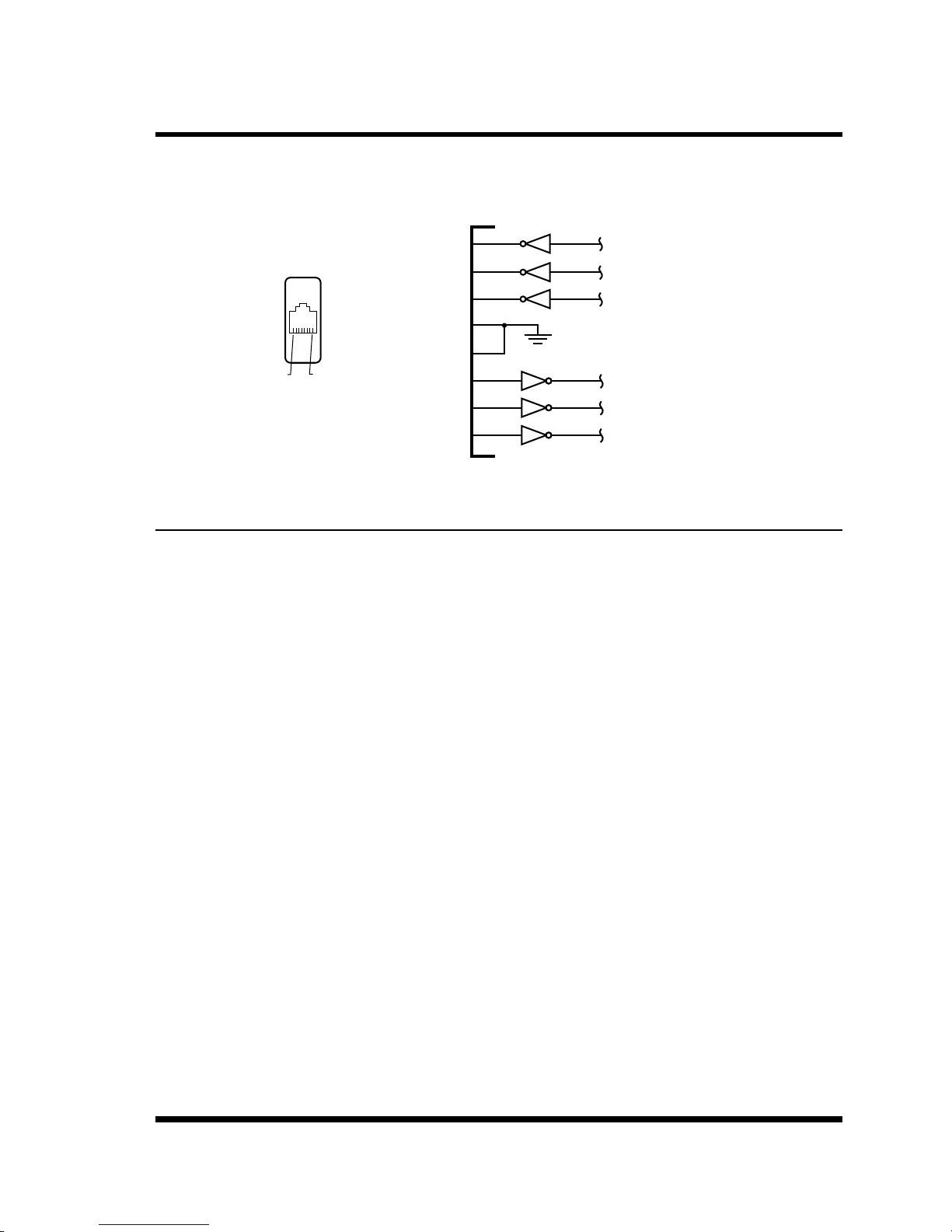
Appendix B. Interface Descriptions
RJ-45
Pin No.
RTS Request to Send
1
2
DTR
TXD
3
4
GND
5
Pin 8
Figure B.1: SetUp Port Interface (RJ45, Cisco Pinout)
Pin 1
RXD
DCD
CTS
6
7
8
B.1. SetUp Port
DCD and DTR hardware lines function as follows:
1. Whenconnected:
a) If either port is set for Modem Mode, the DTR output at either port reects the DCD
input at the other end.
b) If neither port is set for Modem Mode, DTR output is held high (active).
2. Whennotconnected:
Ready Out
Data Out
Ground
Data In
Carrier Detect
Clear to Send
a) If the port is set for Modem Mode, upon disconnect DTR output is pulsed for 0.5
seconds and then held high.
b) If the port is not set for Modem Mode, DTR output is controlled by the DTR Output
option (Serial Port Parameters Menu, Option 23). Upon disconnect, Option 23 allows
DTR output to be held low, held high, or pulsed for 0.5 seconds and then held high.
Apx-2
Page 84

Appendix C. Customer Service
C.1. Contacting Technical Support
Contact information for the Perle Technical Assistance Center (PTAC) can be found at the link
below. A Technical Support Query can be made via this web page:
www.perle.com/support_services/support_request.shtml
Apx-3
Page 85

Appendices
Trademark and Copyright Information
This document must not be reproduced in any way whatsoever, either printed or electronically,
without the consent of:
Perle Systems Limited
60 Renfrew Drive
Markham ON
Canada
L3R 0E1
Perle reserves the right to make changes without further notice, to any products to improve
reliability, function or design.
Microsoft and Internet Explorer are trademarks of Microsoft Corporation.
Netscape is a trademark of Netscape Communications Corporation.
ProComm is a registered trademark of DATASTORM TECHNOLOGIES, INC.
Crosstalk is a registered trademark of Digital Communications Associates, Inc.
VT100 is a trademark of Digital Equipment Corporation.
AT is a registered trademark of International Business Machines Corporation.
JavaScript is a registered trademark of Sun Microsystems, Inc.
© Perle Systems Limited, October, 2011.
Apx-4
 Loading...