

Page 1

PART No. 5500040-16
LINKSTREAM
Installation Guide
Page 2

Copyright Perle Systems Ltd, 2002.
No part of this document may be copied without written permission from
Perle Systems.
The Perle policy is one of continuous development and consequently the equipment
may vary in detail from the description and specification in this publication.
Page 3

LINKSTREAM USER GUIDE
Page 3
TABLE OF CONTENTS
TABLE OF CONTENTS
SECTION PAGE
1.0 GETTING TO KNOW YOUR LINKSTREAM
Documentation 4
Introduction stand alone/rack mount 4
Package contents 4
LINKSTREAM construction 5
Front panel display 5
Reset button 6
Rear panel connections and switch 6
Optional upgrades 7
ISDN2e terminal adaptor 7
User channel expansion card 7
Voice over IP 7
2.0 CONNECTING TO YOUR LINKSTREAM
Power and console connection 8
User channel connection 8
Modem cable 8
Modem controls 9
ISDN connection 9
Serial link connection 9
Ethernet (LAN) connection 10
Ethernet interface/links 10
3.0 COMMAND LINE INTERFACE 11
4.0 CONFIGURING YOUR LINKSTREAM
Quick setup 12
Cold start 14
Accessing management screens 14
Node manager screen structure 16
Statistics screen structure 17
Manual configuration 18
Internet parameters 19
Domain name server configuration 19
Ethernet configuration 20
ISDN call parameter 21
PPP interface - LCP/PAP parameters, IPCP parameters 22
Configure session parameters, System reset 23
5.0 GENERAL INFORMATION
Approvals/RFC list 24
Specification 25
This Installation/User Guide has been designed to assist in the installation of LINKSTREAM in standard
configurations. If the more advanced features of the LINKSTREAM are required then the LINKSTREAM Range
Reference Manual is available. Please contact your supplier for details.
ACKNOWLEDGEMENTS
*Ethernet is a registered trademark of XEROX
*KILOSTREAM and MEGASTREAM are registered trademarks of BT plc
*VT100 is a registered trademark of Digital Equipment Corporation Inc.
Page 4

LINKSTREAM USER GUIDE
Page 4
This User Guide gives quick set up information. For more
detailed information, the LINKSTREAM Range Reference
Manual is available.
The LINKSTREAM is a stand alone product combining
the functions of a terminal server and router in the same
unit. It consists of a metal case with an internal power
supply with 8 asynchronous ports. In addition, there is
an Ethernet port and two WAN interface connections.
The LINKSTREAM function is primarily that of a
distributed data switch working at both the wide and local
area network level. LINKSTREAM combines a host of
features providing the user with two high speed link ports
to access remote local area networks, eliminating the
need for additional bridges and routers. The two high
speed link ports operate at speeds up to 2Mbps enabling
the user to perform remote terminal multiplexing
accommodating Nx64K digital services.
LINKSTREAM is supplied in packaging specially designed
to prevent damage during transit. It is important that
the contents are checked against the list below BEFORE
installing. In the unlikely event of a damaged or missing
item please contact your supplier.
1 x LINKSTREAM unit
1 xMains cable
1 x User Guide
1 x Console cable
GETTING TO KNOW YOUR LINKSTREAM
DOCUMENTATION
INTRODUCTION
STAND ALONE
FUNCTION
PACKAGE CONTENTS
GETTING TO KNOW YOUR LINKSTREAM SECTION 1.0
Page 5
LINKSTREAM USER GUIDE
Page 5
The LINKSTREAM consists of a stand alone case of metal
construction with an internal power supply. Up to two
expansion cards can be fitted to provide additional user
channels, up to a maximum of 24.
The unit is supplied as standard with the following
features:
2 x Serial (WAN) ports
8 x Asynchronous user channels
3 x Ethernet LAN ports 10Base5, 10Base2 and 10BaseT.
Optional upgrade modules are available and are detailed
later in this section.
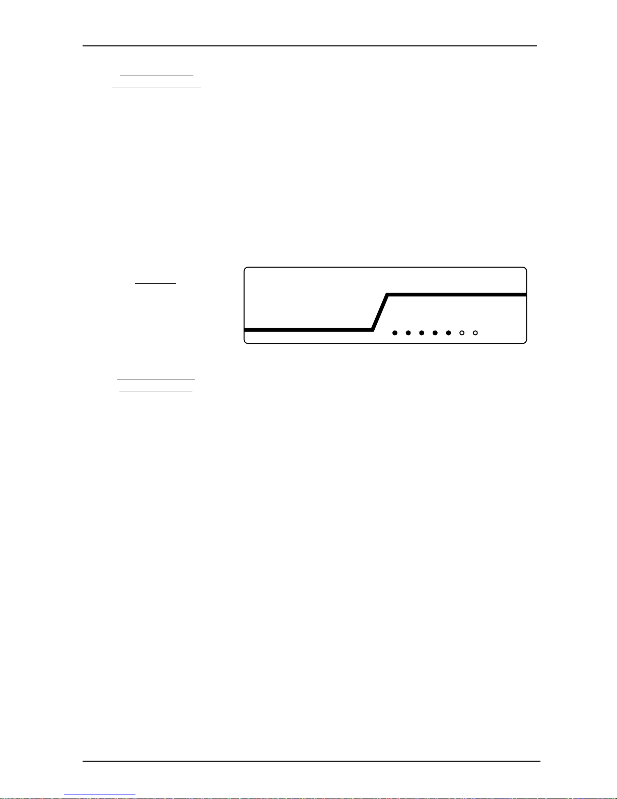
The front panel of the unit is shown below.
RUN
A green LED which flashes at a constant rate of approx.
once every second. This indicates that the power is
applied, all self checks are completed and the unit is
running normally.
LNK0
A green LED which flashes to show data transfer over
Link0. When data transfer ceases, the LED may be left in
the ON or OFF condition.
LNK1
A green LED which flashes to show data transfer over
Link1. When data transfer ceases, the LED may be left in
the ON or OFF condition.
For data transfer over the ISDN the appropriate link LED
will be permanently on.
ENET
A green LED which flashes to show data transfer over the
Ethernet interface. When data transfer ceases the LED
may be left in the ON or OFF condition.
ATTN
An amber LED which when illuminated indicates that a
fault is present or has occurred during system operation.
If lit, please contact your supplier for assistance. If unable
to do this, the fault may be due to a corruption in the
unit's configuration and it is advised that a cold start is
activated and the unit re-configured.
RUN
LNK0
ENET
ATTN
LNK1
RSET
RSRT
FRONT PANEL
LED DISPLAY
Figure 1
LINKSTREAM
front panel
LINKSTREAM
CONSTRUCTION
SECTION 1.0 GETTING TO KNOW YOUR LINKSTREAM
Page 6
LINKSTREAM USER GUIDE
Page 6
There are also two recessed push buttons on the front
panel:
RSET This performs a 'warm start' to the system in
that it clears down all queues and restarts the
system with existing configuration parameters.
RSRT This button is used to perform a full 'cold start'
and is used in conjunction with RSET.
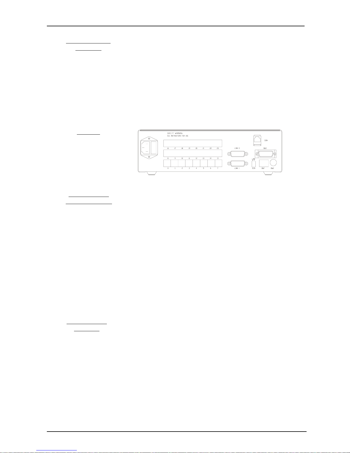
The rear panel of the unit provides for all connections to
the unit.
FRONT PANEL
BUTTON
GETTING TO KNOW Y OUR LINKSTREAM SECTION 1.0
Connections are:
❑ Mains Power Inlet
110-240V socket outlet to be nearby and accessible.
❑ 0 - 23
Up to 24 user channels, 8 on the base unit and 8
on each expansion card.
❑ LINK 0
Serial WAN link.
❑ LINK 1
Serial WAN link.
❑ ISDN
ISDN2e Terminal Adaptor
❑ 10b5, 10b2, 10bT
Ethernet interfaces for the various types of
Ethernet connection.
See page 9 for optional upgrades.
This rear panel switch selects the serial link and ISDN
interface.
Select 'ISDN' for ISDN.
Select 'LINK' for serial link connector.
Figure 2
LINKSTREAM
rear panel
REAR PANEL
CONNECTIONS
REAR PANEL
SWITCH
Page 7

LINKSTREAM USER GUIDE
Page 7
OPTIONAL UPGRADES
LINKSTREAM - ISDN2e Terminal Adaptor
8 Channel expansion card
Voice over IP card
Configured automatically or manually, one or both of the
WAN links can be replaced with an ISDN interface running
at 64Kbps on each link. The module is plugged into rear
socket on the LINKSTREAM.
LINKSTREAM switch settings
This rear panel switch is for each serial link
Select 'ISDN' for ISDN.
Select 'LINK' for serial link connector.
The ISDN function within LINKSTREAM has been designed
to offer the same operation to the user whether the
internal ISDN module is installed or an external Terminal
Adaptor is connected to the LINK0 or LINK1 interface.
Stand alone and rackmount units are supplied with 8 user
channels. Up to 24 user channels can be supported by
the addition of LINKSTREAM expansion cards. These are
ordered separately and are fitted by the user.
The LINKSTREAM VIP card provides 2 compressed voice/
fax channels for IP networks.
SECTION 1.0 GETTING TO KNOW YOUR LINKSTREAM
INTEGRAL ISDN2e
TERMINAL ADAPTOR
USER CHANNEL
EXPANSION CARD
VOICE OVER IP
CAUTION
INSTALLATION OF MODULES SHOULD BE CARRIED OUT
BY QUALIFIED SERVICE PERSONEL ONLY.
Page 8

LINKSTREAM USER GUIDE
Page 8
On power up, the LEDs on the front panel illuminate while
the LINKSTREAM performs system checks. Once
successfully completed the RUN LED flashes at a constant
rate (approx. once every second).
If the RUN LED does not flash at a constant rate, or the
ATTN LED is on, then do not continue with the
installation. Contact your supplier for advice.
Connect the RJ45 end of your console cable into any of
the user channels. Connect the other end of the console
cable into the serial port of your computer or terminal,
tighten the locating screws where applicable.
To make up your own console cable the RJ45 socket pin
outs are detailed in the 'User Channel Connection' section,
below.
The user channel RJ45 sockets present asynchronous
V.24/V.28 as a DCE with the following pin outs :
LINKSTREAM Terminal
RJ45 DB25 Function
1 <<-- 4 R TS
2 <<-- 20 D TR
3 <<-- 2 T XD
4 -->> 8 DCD
5 -->> 3 R X D
6 7 GND
7 -->> 6 DS R
8 -->> 5 CT S
Please ensure that user channel cables do not exceed V.24/
V.28 (RS232) recommended lengths or data corruption
can occur.
The following cable specification is typical to allow
bidirectional modem access. We recommend that you
check with your modem manual to ensure that the
specification is suitable.
LINKSTREAM Path Modem
DB25
RTS 1 <<-- 22 RINGIN
D T R 2 <<-- 5 CT S
T X D 3 <<-- 3 R X D
DCD 4 -->> 2 0 DTR
R X D 5 -->> 2 T XD
GND 6 7 GND
CT S 8 -->> 4 R TS
POWER CONNECTION
CONSOLE
CONNECTION
CONNECTING TO YOUR LINKSTREAM
MODEM CABLE
USER CHANNEL
CONNECTION
CONNECTING TO YOUR LINKSTREAM SECTION 2.0
Page 9

LINKSTREAM USER GUIDE
Page 9
The user channels on LINKSTREAM have 5 control lines
for modem access, 3 outputs (DCD, DSR, CTS) and 2 inputs
(RTS, DTR). The 2 inputs are monitored for call status
whilst 2 outputs (DCD and CTS) are used by LINKSTREAM
to control access. DSR is permanently 'ON' by being tied
high through a resistor.
LINKSTREAM is capable of working in 3 different modes
with a modem to suit every application :
1. Initiate call only (Dial Out)
2. Receive calls only (Dial In)
3. Bidirectional calls (Dial In/Out)
This User Guide only deals with bidirectional call set up.
Full details of configuration for each mode are available
in the LINKSTREAM Range Reference Manual.
An optional ISDN2e Terminal Adaptor (TA) can be installed
in LINKSTREAM. This can be used to replace one or both
of the WAN links with an ISDN interface running at 64Kbps
on each link.
We recommend that you configure your LINKSTREAM
before connecting the TA or serial link cable. The ISDN
cable is supplied with the TA. A second serial link cable
can be ordered separately for connection to a NTU.
MODEM CONTROLS
SECTION 2.0 CONNECTING TO YOUR LINKSTREAM
ISDN CONNECTION
Page 10

LINKSTREAM USER GUIDE
Page 10
The following cable is used to connect to V.35 DCEs.
LINKSTREAM DCE:
15-way D plug MRAC 345-J2 Function
2 P TXD-A
9 S TXD-B
4 R RXD-A
1 1 T RXD-B
3 C RTS
8 B Ground
5 F DCD
1 Y TXC-A
7 AA(a) TXC-B
6 V RXC-A
1 3 X RXC-B
14 U TXC(Ext)-A
1 5 W TXC(Ext)-B
The following cable is used to connect low speed X.21bis
Kilostream or a modem with a V.24 interface.
LINKSTREAM Modem:
15-way D plug 25-way D plug Function
2 2 TXD
4 3 RXD
3 4 RT S
8 7 Signal Ground
5 8 DCD
1 15 TXC
6 17 RXC
14 24 TXC(Ext)
The 15-way D socket uses UNC 440 retention screws.
We recommend that you configure your LINKSTREAM
before connecting the Ethernet port.
Care should be taken when connecting the Ethernet port
of the LINKSTREAM to your network. Ensure that you
follow the usual precautions as laid down in the Ethernet
guidelines. If unsure of connection procedures for
Ethernet then contact your supplier for advice.
10Base5, 10Base2 and 10BaseT interfaces are provided
on the stand alone LINKSTREAM although only one may
be used at any time. Failure to observe this will corrupt
the data and prevent correct operation. Selection of the
interface is by use of the 6-way multi-coder between
column pairs as set out below:
10BaseT RJ45 Link columns A-B (factory default).
10Base2 BNC Link columns B-C
10Base5 15 way D Link columns C-D
V.35 SERIAL LINK
CONNECTING TO Y OUR LINKSTREAM SECTION 2.0
V.24/V.28 SERIAL LINK
NOTE:
ETHERNET
CONNECTION
ETHERNET
INTERFACE
LINKS
Page 11

LINKSTREAM USER GUIDE
Page 11
The LINKSTREAM presents a Command Line Interface to
the user when attached to any of the channels. The unit
is activated by pressing any key and will respond with
Welcome to LINKSTREAM
LINKSTREAM >
The user is then able to enter any of the commands in
response to the system prompt. The commands can be
entered in lower or upper case and can be abbreviated to
just the highlighted letters identified. 'Space' or TAB can
be used to separate commands and arguments. The
Backspace and Delete keys are operational to edit lines.
The Command Line Interface also gives the user access
to the Node Manager resident in the local unit or in any
other LINKSTREAM on the network.
A summary of the commands is given below.
Command Arguments Description
Close <session>
Close a specific connection
Help Show help page
LOCk Lock current port
LOGin <host> <port> Log in to configuration
manager
LIsten Put current port into
'Listen' state
Open <host> <port> Open a transparent
connection
Ping [forever] <host>[t] Send ICMP Ping requests
PPp Start PPP on this port
Quick Start quick setup Menu
Resume <session> Resume a specific
session
SEnd <code><sess> Send Telnet code (BRK/
IP/AO/AYT/EC/EL)
SHow
<[sess][names][map]
Show Telnet sessions or
[arp][panic]> Name Server table
SLip Start SLIP on this port
Telnet <host> <port> Open a Telnet connection
Version Display TCP version
number
Xping [forever]<host>[t] Send IPX ping requests
SECTION 3.0 COMMAND LINE INTERFACE
INTRODUCTION
COMMAND LINE INTERFACE
Page 12

LINKSTREAM USER GUIDE
Page 12
The following steps provide basic configuration
information to enable you to get started. For more
detailed information and 'fine-tuning', refer to the
LINKSTREAM Range Reference Manual.
SECTION 4.0 CONFIGURING YOUR LINKSTREAM
Quick Setup Worksheet
Product Type
Site Name
Prepared by Date
It is advisable to fill out this worksheet before attempting to configure a
LINKSTREAM using the Quick Setup Menu.
1. IP traffic only? yes___/no___
If no, then Quick Setup cannot be used.
2. Leased Line? yes___/no___
If no, then Quick Setup cannot be used.
3. Network Address of directly attached Ethernet ___.___.___.___
Subnet Mask of directly attached Ethernet. ___.___.___.___/none
4. Unique IP Address assigned to LINKSTREAM ___.___.___.___
5. Active RIP to be used on all network ports? yes___/no___
6. Default Gateway to be defined? yes___/no___
If yes, what is the address? ___.___.___.___
7. Type of Serial Link0 addressing
numbered ___/unnumbered ___
If numbered, what is the IP address? ___.___.___.___
What is the subnet mask? ___.___.___.___ /none ___
Type of Serial Link1 addressing
numbered ___/unnumbered ___
If numbered, what is the IP address? ___.___.___.___
What is the subnet mask? ___.___.___.___ /none ___
8. Voice Port0 enabled? on___/off___
Voice Port0 Type: Tie___/FXO___/FXS___
Voice Port0 Remote IP Address: ___.___.___.___
Voice Port0 Remote Port ___
Voice Port1 enabled? on___/off___
Voice Port1 Type: Tie___/FXO___/FXS___
Voice Port1 Remote IP Address: ___.___.___.___
Voice Port1 Remote Port ___
Voice Port2 enabled? on___/off___
Voice Port2 Type: Tie___/FXO___/FXS___
Voice Port2 Remote IP Address: ___.___.___.___
Voice Port2 Remote Port ___
Voice Port3 enabled? on___/off___
Voice Port3 Type: Tie___/FXO___/FXS___
Voice Port3 Remote IP Address: ___.___.___.___
Voice Port3 Remote Port ___
QUICK SETUP
Page 13

LINKSTREAM USER GUIDE
Page 13
1. Cold start the LINKSTREAM. This will clear any pre-existing
configuration and will put the unit in a known state of default
values.
2. Connect a terminal or PC running a suitable VT100 emulator
package such as Procomm or Hyperterminal, set to 9600 baud, 8
data bits, 1 stop bit, to the LINKSTREAM console port. Activate
the console port by typing <cr> so the LINKSTREAM> prompt
appears.
3. Type Quick followed by a <cr> to enter the Quick Setup Menu.
4. Enter the default password, which is 6 full stops: . . . . . .<cr>
5. When prompted for the Ethernet IP address, enter the value
from the worksheet. Note that an Ethernet IP Address must be
entered.
6. When prompted, enter the Subnet Mask. If subnetting is not
being used, accept the default value which is automatically set
to 255.255.255.0 for class C addresses.
7. To set Serial Link 0 with unnumbered IP addressing:
Serial Link0 Enable (on/off) [off]: on <cr>
Link0 Numbered or Unnumbered IP [numbered]:
unnumbered <cr>
8. If Serial Link1 is not used,
set Serial Link1 Enable (on/off) [off]:<cr>
9. If the worksheet states RIP is enabled, RIP (on/off) [off]: on <cr>
10. If the worksheet states no default gateway,
Default Gateway (x.x.x.x) [none]: <cr>
11. Voice Port0 is used, and is connected to Port0 of the remote
LINKSTREAM.
Voice Port0 (on/off) [off]: on <cr>
Port0 Type (Tie/FXO/FXS) [tie]L Tie <cr>
Port0 Remote IP Address (x.x.x.x) [0.0.0.0:192.168.2.45
Port0 Remote Port (0-3) [0]: 0 <cr>
12. If Voice Port1 is not to be used, Voice Port1 (on/off) [off] <cr>
If Voice Port1 is required, configure as above.
13. When prompted, save these changes and reboot (yes/no) [no]:
yes <cr>
The 'Saving settings' message will be displayed and dots will
appear as the parameters are stored. Within a few seconds the
LINKSTREAM will restart, and be ready for operation.
The configuration can now be 'fine-tuned' if necessary by using
the management screens.
SECTION 4.0 CONFIGURING YOUR LINKSTREAM
Page 14

LINKSTREAM USER GUIDE
Page 14
CONFIGURATION
CONFIGURING YOUR LINKSTREAM
CONFIGURING Y OUR LINKSTREAM SECTION 4.0
This section gives a brief overview of the LINKSTREAM using
the Node Manager. Full details of all configuration screens
are given in the LINKSTREAM Range Reference Manual.
The LINKSTREAM can be completely restarted using the
cold start mechanism.
NB This will remove all the user-entered configurations
and return all parameters to their default values.
A cold start is carried out as follows:
i) Hold in the 'RSET' and 'RSRT' buttons.
ii ) Release the 'RSET' button.
iii) Release the 'RSRT' button.
The unit will then restart. All the front panel LEDs will
illuminate for approximately 10 seconds. They will then
all go out except for the RUN LED which will remain flashing.
Attach a VT100 type terminal or PC running VT100
emulation to any of the user channels.The management
port is activated by pressing any key and will respond with:
Welcome to LINKSTREAM
LINKSTREAM >
Enter the command LOG <CR> (local unit)
or the command LOG with IP address <CR> (remote unit).
The LINKSTREAM will respond with the Log-on screen
(see Fig.1 below).
To log-on, enter the user identity (up to 8 characters) and
the correct password. The default values are:
User Identity : manager
Password : ...... (six full stops)
Node : No Name
Log On
=======
SYSTEM MSG : Enter user Identity
LINKSTREAM version x.x
User Identity : ..........
Password :
ACCESSING
CONFIGURATION
MANAGEMENT
Figure 1
Log-on
screen
COLD START
Page 15

LINKSTREAM USER GUIDE
Page 15
SECTION 4.0 CONFIGURING YOUR LINKSTREAM
A number of control characters are used to perform
specific functions, independent of the screen currently
displayed.
CTRL-X invokes the main menu from any other screen
as long as the user is logged in.
CTRL-Y returns the user from the current menu to the
previous menu in the sequence.
CTRL-A used as a log-off command which is effective
from all screens. On entry of the character,
the system will return to the command line
prompt.
CTRL-Z moves the cursor to the last configurable
field on the screen.
Two characters are used to move through multiple pages
of data such as routing tables. They are therefore only
active on certain screens.
CTRL-F go Forwards to next page.
CTRL-B go Backwards to the previous page.
Other control characters, specific to certain screens, are
described in the LINKSTREAM Range Reference Manual.
Figure 2
Main
menu
screen
Node : No Name
MAIN MENU
==========
1. Configuration
2. Statistics
Select option:
ctrl<a> - Log Off
Fri 01 Jan 199- 00.00
SYSTEM MSG : Enter option number
Page 16

LINKSTREAM USER GUIDE
Page 16
LOGON
MAIN MENU
CONFIGURATION (1)
SYSTEM CONFIGURATION (1)
NODE SYSTEM PARAMETERS
USER IDENTITIES AND PASSWORDS
USER AUTHENTICATION TABLE
USER MENU
ISDN CALL MANAGEMENT TABLE
UPLOAD/DOWNLOAD CONFIGURATION
SNMP CONFIGURATION
RADIUS CONFIGURATION
INTERNET PROTOCOL CONFIGURATION (2)
SYSTEM INTERNET PARAMETERS 19
IP STATIC ROUTING TABLE
DOMAIN NAME SERVER PARAMETERS 19
DOMAIN NAME SERVER TABLE
IP FILTER TABLE
IP AUTOFORWARDING TABLE
IPX PROTOCOL CONFIGURATION (3)
SYSTEM IPX PARAMETERS
IPX STATIC ROUTING TABLE
IPX STATIC SERVICES TABLE
NETWORK INTERFACE CONFIGURATION (4)
ETHERNET INTERFACE PARAMETERS 20
SERIAL LINK INTERFACE PARAMETERS
ISDN/MODEM CALL PARAMETERS 21
PERLE LINK PARAMETERS
PPP-LINK LCP /PAP PARAMETERS 22
PPP-LINK IPCP PARAMETERS 22
PPP-LINK IPXCP/IPXWAN PARAMETERS
PPP-MULTILINK PARAMETERS
SLIP INTERFACE PARAMETERS
CHANNEL CONFIGURATION (5)
CHANNEL INTERFACE PARAMETERS
CHANNEL SESSION PARAMETERS 23
CHANNEL STRINGS CONFIGURATION
RESET/COPY CHANNEL PARAMETERS
VOICE CONFIGURATION
SYSTEM RESET (6) 23
STATISTICS
GENERAL INFORMATION
CONFIGURING Y OUR LINKSTREAM SECTION 4.0
PP
PP
P
aa
aa
a
gg
gg
g
e no.e no.
e no.e no.
e no.
NODE MANAGER
SCREEN STRUCTURE
CONFIGURATION
The diagram below gives the overall structure of the
screens within the Node Manager, showing the pathways
through the system.
Page 17

LINKSTREAM USER GUIDE
Page 17
LOGON
MAIN MENU
CONFIGURATION
STATISTICS (2)
DISPLAY NODE STATISTICS (1)
SYSTEM STATISTICS
WEEKLY CALL STATISTICS
TODAYS CALL STATISTICS
RADIUS STATISTICS
DISPLAY IP STATISTICS (2)
IP STATISTICS
ICMP STATISTICS
UDP STATISTICS
TCP STATISTICS
ARP STATISTICS
TCP CONNECTION TABLE
IP (RIP) ROUTING TABLE
DNS TABLE
DISPLAY IPX STATISTICS (3)
IPX STATISTICS
IPX (RIP) STATISTICS
IPX (RIP) ROUTING TABLE
IPX (SAP) STATISTICS
IPX SERVICE (SAP) TABLE
IPX NETBIOS STATISTICS
IPX PING STATISTICS
IPX SPOOFING STATISTICS
DISPLAY INTERFACE STATISTICS (4)
INTERFACE STATISTICS
PPP STATUS SUMMARY
PPP LINK LEVEL STATISTICS
PPP NETWORK LEVEL STATISTICS
IPX WAN INTERFACE STATISTICS
DISPLAY USER CHANNEL STATISTICS (5)
USER CHANNEL SUMMARY
USER CHANNEL SESSIONS/STATISTICS
STATISTICS RESET (6)
NODE MANAGER
SCREEN STRUCTURE
STATISTICS
-Continued
SECTION 4.0 CONFIGURING YOUR LINKSTREAM
Page 18
LINKSTREAM USER GUIDE
Page 18
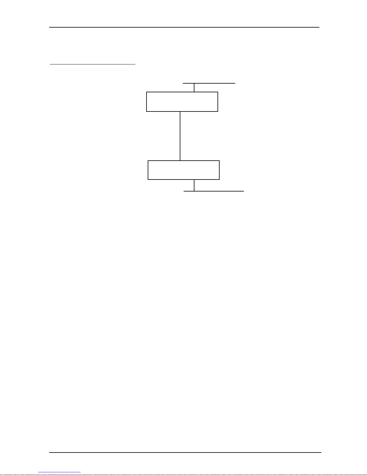
To manually configure the unit for the example above,
follow through the configuration menus detailed on
the following
pages.
Note that the
highlighted fieldshighlighted fields
highlighted fieldshighlighted fields
highlighted fields on each screen require
you to enter a value detailed by the corresponding 'tick
box' situated below each screen.
CONFIGURING YOUR LINKSTREAM SECTION 4.0
PPP/ISDN
Network 128.16
DNS table:128.16.0.64 Local
128.17.0.64 Remote
Network 128.17
NB Factory default settings
MANUAL CONFIGURATION
IP Addr. = 128.16.0.64
Default Gateway = 128.18.0.2
Link 0 = 128.18.0.1
Link 0 = 128.18.0.2
Default Gateway = 128.18.0.1
IP Addr. = 128.17.0.64
Page 19

LINKSTREAM USER GUIDE
Page 19
LOGON
MAIN MENU
CONFIGURA TION
þ Default Gateway
This address overrides any learned default but it
is not advertised over RIP. Set for 128.18.0.2
Enter 'Y' to 'Accept:' to save displayed values.
The following parameter
must be defined:
SYSTEM INTERNET
P ARAMETERS
INTERNET PROT OCOL
CONFIGURA TION
LOGON
MAIN MENU
CONFIGURA TION
DOMAIN NAME SERVER
CONFIGURA TION
INTERNET PROT OCOL
CONFIGURA TION
þ Domain Name
Enter the Domain Name for the unit - up to 255
characters. Use ctrl<d> to delete any characters
after the cursor.
Enter 'Y' to 'Accept:' to save displayed values.
SECTION 4.0 CONFIGURING YOUR LINKSTREAM
TT
TT
T
o moo mo
o moo mo
o mo
ve the curve the cur
ve the curve the cur
ve the cur
sor up andsor up and
sor up andsor up and
sor up and
dodo
dodo
do
wn,wn,
wn,wn,
wn,
use the cur use the cur
use the cur use the cur
use the cur
sor arrsor arr
sor arrsor arr
sor arr
oo
oo
o
w kew ke
w kew ke
w ke
ysys
ysys
ys
on yon y
on yon y
on y
our keour ke
our keour ke
our ke
yboaryboar
yboaryboar
yboar
dd
dd
d
Node: No Name Mon 01 Jan 199 00:00
INTERNET P ARAMETERS
====================
Global RIP status: Enabled Default Gate wa y: 128.18.0.2
IP Checksum: Enabled IP Options: Enabled
IP Default TTL: 15
TCP Checksum: Enabled TCP Options: Enabled
TCP Max Rexmt Timeout: 20 TCP Retry Count: 5
TCP Keep Alive Timer: 0 TCP Keep Alive Interval: 1
TCP Keep Alive Count: 2
T elnet Protocol Base No: 1000 Transparent Protocol
Console Protocol Port No: 23 Base No: 2000
Accept: ?
ctrl<a> - Log Off
ctrl<x> - Main Menu ctrl<y> - Previous Menu ctrl<z> - Last Field
------------------------------------------------------------------------------------------------------------------SYSTEM MSG: Node Routing Information Protocol (use '<' or '>' to toggle)
Node: Local Mon 01 Jan 199- 00:00
DOMAIN NAME SERVER CONFIGURATION
===================================
DNS Resolver: Disabled
Domain Name: Local
Primary DNS Server: 0.0.0.0
Secondary DNS Server: 0.0.0.0
Default Domain Suffix 1: None
Default Domain Suffix 2: None
Accept: ?
ctrl<a> - Log Off
ctrl<x> - Main Menu ctrl<y> - Previous Menu ctrl<z> - Last Field
--------------------------------------------------------------------------------------------------------------------SYSTEM MSG: Toggle '<' or '>' to make selection
The following parameter
must be defined:
Page 20

LINKSTREAM USER GUIDE
Page 20
Link Level Protocols
IP/ARP
þ Status
Use to enable support for IP/ARP protocols on the
LINKSTREAM. Set to Enabled.
þ IP Address
Enter IP address of the unit. Set to 128.16.0.64
(local end).
Enter 'Y' to 'Accept:' to save displayed values.
After setting the above, LINKSTREAM will need
rebooting. This can be achieved by either pressing the
RSET button or via the system reset screen.
CONFIGURING YOUR LINKSTREAM SECTION 4.0
LOGON
MAIN MENU
CONFIGURA TION
ETHERNET INTERFA CE
P ARAMETERS
NETWORK INTERF ACE
CONFIGURA TION
Node: Local Mon 01 Jan 199- 00:00
ETHERNET CONFIGURA TION
========================
Ethernet Address: 00:00:00:00:00:00
Frame Format: Ethernet II
Link Level Protocols
IP/ARP
Status: Enabled
====== IP Address: 128.16.0.64 Subnet Mask: 0.0.0.0
RIP Status : Enabled RIP T ype: RIP1 only
RIP Default Metric: 16 NT Forwarding: Disabled
IPX Status: Disabled
=== Network: 00000000
RIP Status: Disabled NetBios Forwarding: Disabled
SAP Status: Disabled
Accept : ?
ctrl<a> - Log Off
ctrl<x> - Main Menu ctrl<y> - Previous Menu ctrl<z> - Last Field
---------------------------------------------------------------------------------------------------------------------SYSTEM MSG: Enter the Internet Address of this interface
The following parameters
must be defined:
Page 21

LINKSTREAM USER GUIDE
Page 21
LOGON
MAIN MENU
CONFIGURA TION
ISDN P ARAMETERS
NETWORK INTERF ACE
CONFIGURA TION
Note that the selected interface should be disabled to
set up ISDN parameters. If the interface has not been
previously used, it must first be enabled then disabled
before ISDN call parameters can be set. This is to enable
a valid clock for the interface.
þ Interface
Select serial link 0.
þ ISDN Mode
Dial In Only = Will only accept external calls.
Dial Out Only = Will only make calls from the
unit.
Dial In & Out = Will both make and accept calls.
þ Call Retry Delay
The call retry delay is the time taken for a retry
after a failed attempt to connect. Both ends of the
link must be set differently.
þ Prime Number
This is the ISDN number to be called by the
LINKSTREAM.
þ TA Mode
Note: Enter TA Mode to check that the TA responds
prior to using Auto Configuration Mode.
Type AT<CR>. TA should return 'OK'.
þ Auto Configuration Mode - Link 0
This mode automatically configures the TA.
Select NORMAL. Enables Link 0 to answer.
þ Auto Configuration Mode - Link 1
Select serial link 1, select Auto Configuration
Mode.
Select OFF to disable Link 1 from answering.
Enter 'Y' to 'Accept:' to save displayed values.
SECTION 4.0 CONFIGURING YOUR LINKSTREAM
Node: Local Mon 01 Jan 199- 00:00
ISDN CALL P ARAMETERS
=====================
Interface: Serial Link 0
Link Protocol Status: None
ISDN Mode: Dial In or Out Dialling Mode: ATD Signal
DCD Delay: 5 Prime Number: ....................
Call Retries: 3 Backup Number ....................
Call Retry Delay: 8 (4 other end)
No Data Call Timeout: 10
Minimum Call Time: 60
Auto. configuration: Normal
Force Link Negotiation: Disabled
Spoofing: Enabled
Login Script:
T A Mode: Data
Accept: ?
ctrl<a> - Log Off
ctrl<x> - Main Menu ctrl<y> - Previous Menu ctrl<z> - Last Field
-------------------------------------------------------------------------------------------------------------------SYSTEM MSG: Toggle '<' or '>' to make selection
These parameters only
need configuring if an
ISDN interface is
required.
Page 22

LINKSTREAM USER GUIDE
Page 22
CONFIGURING YOUR LINKSTREAM SECTION 4.0
LOGON
MAIN MENU
CONFIGURA TION
PPP LCP P ARAMETERS
NETWORK INTERF ACE
CONFIGURA TION
þ Interface
Select the appropriate serial link (0-1). Set for 0.
þ Status
Set for Enabled.
þ MRU Size
Change only if voice is being used.
Set to 240 (voice and data).
Set to 1500 (data only).
Enter 'Y' to 'Accept:' to save displayed values.
Node: Local Mon 01 Jan 199- 00:00
PPP INTERFACE - LCP/PAP PARAMETERS
===================================
Interface: Serial Link 0
Status: Enabled
LCP
Echo Interval: 0 Echo Fails: 5
MRU Size: 1500 ACCM: N/A
Security: None Link Compression: Disabled
Multilink: Disabled
PAP
Remote Username:
Remote Password:
Accept: ?
ctrl<a> - Log Off ctrl<b> - IPXCP Config ctrl <f> - IPCP Config
ctrl<x> - Main Menu ctrl<y> - Previous Menu ctrl<z> - Last Field
--------------------------------------------------------------------------------------------------------------------SYSTEM MSG: Select network interface ('<' or '>' to toggle)
The following parameters
must be defined
LOGON
MAIN MENU
CONFIGURA TION
PPP IPCP P ARAMETERS
NETWORK INTERF ACE
CONFIGURA TION
Node: Local Mon 01 Jan 199- 00:00
PPP INTERFACE - IPCP PARAMETERS
===================================
Interface: Serial Link 0
Status: Enabled
Local IP Address: 128.18.0.1 Subnet Mask: 255.255.0.0
Remote IP Address: 0.0.0.0 NT Forwarding: Disabled
Header Compression: None
RIP Status: Disabled RIP Type: RIP1 only
Default Gatewa y Metric: 16 RIP Metric: 1
Default Route: Disabled
Accept: ?
ctrl<a> - Log Off ctrl<b> - LCP Config ctrl <f> - IPXCP Config
ctrl<x> - Main Menu ctrl<y> - Previous Menu ctrl<z> - Last Field
-------------------------------------------------------------------------------------------------------------------SYSTEM MSG: Select network interface ('<' or '>' to toggle)
þ Status
Set to Enabled.
þ Local IP Address
Enter IP address of the selected interface.
Set to 128.18.0.1
Enter 'Y' to 'Accept:' to save displayed values.
The following parameters
must be defined
Page 23

LINKSTREAM USER GUIDE
Page 23
SECTION 4.0 CONFIGURING YOUR LINKSTREAM
Node: Local Mon 01 Jan 199- 00:00
CONFIGURE SESSION P ARAMETERS
==============================
Channel No: 0 T elnet T ransparent
Internet Address: 0.0.0.0 Protocol Port Numbers: 1000 2000
Access: Remote Session Mode: Transparent Def ault P ort: 23
Maximum Sessions: 4 Idle Timeout: 0 TCP Window Size: 1024
Autocall Destination: None
Preferred Destination: None
Data Transfer Node Parameters:
T erminal Type: unknown
Session Echo Node: Telnet Remote
Accept: ?
ctrl<a> -Log off
ctrl<x> - Main Menu ctrl<y> - Previous Menu ctrl<z> - Last Field
-------------------------------------------------------------------------------------------------------------------------------SYSTEM MSG: Enter chan no. ( 0 to [max no. chans - 1] )
LOGON
MAIN MENU
You have now successfully set up your local
LINKSTREAM. Before configuring the remote unit,
perform a system reset. This screen is entered to reboot
the system and requires a confirmation response.
LOGON
MAIN MENU
CONFIGURA TION
SYSTEM RESET
Node: Local Mon 01 Jan 199- 00:00
SYSTEM RESET
============
Warm Start Node: . Confirm: .
ctrl<a> - Log Off ctrl<x> - Main Menu ctrl<y> - Previous Menu
-----------------------------------------------------------------------------------------------------------------SYSTEM MSG:
Each channel (0-23) to be configured as follows:
þ Channel Number
Select channel number.
þ Access
Select to Remote at local and set to Dedicated
at the remote end.
þ Session Mode
Select Transparent at both local and remote.
þ Autocall Destination
Enter a destination IP address. Set as 128.16.0.64
remote only.
Enter 'Y' to 'Accept:' to save displayed values.
CONFIGURATION
CHANNEL
CONFIGURATION
CHANNEL SESSION
P ARAMETERS
The following parameters
must be defined
Page 24

LINKSTREAM USER GUIDE
Page 24
APPROVALS
The LINKSTREAM meets the following European standards:
BABT Approval No.
NS/2220/1/P/603943
Safety
EN 60950
Network safety
EN 41003
Network connection
NET1 clause 8 and Annex A9 (X.21 variant only)
ISDN
Euro-ISDN to I-CTR3
The LINKSTREAM carries the '
' mark.
GENERAL INFORMATION SECTION 5.0
WARNING
For continued user safety protection, and for protection
of the Telecommunications Network, this equipment must
be connected to a protective earth.
For continued protection of the Telecommunications
Network only SELV circuits should be connected to any
user port.
Note: User channels are labelled 0 to 23 on the stand alone
unit.
WARNING
SAFETY NOTICE
CAUTION
The LINKSTREAM has a component containing a lithium battery, on the base
card. There is a danger of explosion if this is incorrectly replaced. Replace
only with the same type. Dispose of used batteries properly and do NOT cut
open or expose to a naked flame or to temperatures outside the range of
-20 to +60 degrees C.
Page 25

LINKSTREAM USER GUIDE
Page 25
SECTION 5.0 GENERAL INFORMATION-SPECIFICATION
GENERAL
Dimensions
285 x 260 x 88 mm. (LINKSTREAM).
Weight
Up to 1.6 kg. Depending on options.
Environment
0° to 40°C operating, -20° to 40°C storage,
0 - 95% RH non-condensing.
Processor
16 bit Microcontroller running at 33MHz.
Memory
2Mbyte Flash, 4Mbyte SRAM.
Protocols
TCP/IP/IPX & Telnet over LAN/WAN interfaces.
Network buffer size
82 - 1514 bytes.
POWER SUPPLY
Type
Internal.
Power consumption
40W.
Power input
110V to 240V AC-5% + 10% 50 - 60Hz.
Power output
+5V DC, +12V DC, -12V DC regulated to 1.5%.
Overload and short circuit protection.
ETHERNET INTERFACE
10Base5
15-way D socket (stand alone and rack mount).
10Base2
BNC socket (stand alone).
10BaseT
RJ45 socket (stand alone).
TRUNK INTERFACES
Two trunk interfaces are provided, each with the following features:
Speeds
2.4K - 1Mbps.
Mode
Synchronous.
Clock source
Internal and External.
Protocol
PPP.
Data Compression
VJ, Lempel-Ziv, STAC, CSLIP, NCP.
Diagnostics
Local and Remote loopbacks.
Interface type
V.24, V.35, X.21 (V.11) selected by use of
appropriate module.
Connector
15-way D socket.
ISDN
Basic rate (2B+D) ISDN connection providing the S-Bus
interface onto the ISDN/2E network, presented as an
8-way RJ45 socket.
Provides 2 x 64Kbps synchronous channels for
connection to the trunk interfaces of the LINKSTREAM.
CONSOLE PORT
Speeds
50bps - 57.6Kbps.
Mode
Asynchronous.
User channel buffer
82 - 1514 bytes.
Parity
None, Odd, Even, Force Odd, Force Even.
Stop bits
1, 1.5, 2 bits.
Data bits
5 - 8 bits.
Flow control
XON/XOFF, DTR/RTS, IXON/XOFF.
Interface type
V.24/V.28.
Connector
RJ45 socket.
Protocols
SLIP/CSLIP/PPP/TRANSPARENT.
Page 26

 Loading...