

Perle IOLAN SDS2 LA, IOLAN SDS2 LE, IOLAN SDS2 L, IOLAN SDS4 L Hardware Installation Manual
Page 1
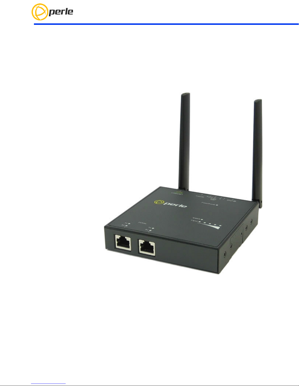
IOLAN SDS2 LA/LE Hardware Installation Guide
www.perle.com
Updated: October 2017
Version A.1.10.25.2017
Document Part#:5500410-10 (Rev C)
Page 2

THE SPECIFICATIONS AND INFORMATION REGARDING THE PRODUCTS IN THIS GUIDE ARE SUBJECT TO CHANGE
WITHOUT NOTICE. ALL STATEMENTS, INFORMATION, AND RECOMMENDATIONS IN THIS GUIDE ARE BELIEVED TO BE
ACCURATE BUT ARE PRESENTED WITHOUT WARRANTY OF ANY KIND, EXPRESS OR IMPLIED. USERS MUST TAKE
FULL RESPONSIBILITY FOR THEIR APPLICATION OF ANY PRODUCTS.
This equipment has been tested and found to comply with the limits for a Class A digital device, pursuant to part 15 of the FCC
rules. These limits are designed to provide reasonable protection against harmful interference when the equipment is operated in a
commercial environment. This equipment generates, uses, and can radiate radio-frequency energy and, if not installed and used in
accordance with this hardware guide may cause harmful interference to radio communications. Operation of this equipment in a
residential area is likely to cause harmful interference, in which case users will be required to correct the interference at their own
expense.
Modifications to this product not authorized by Perle could void the FCC approval and negate your authority to operate the product.
Perle reserves the right to make changes without further notice, to any products to improve reliability, function, or design.
Perle, the Perle logo, and IOLAN SDS L are trademarks of Perle Systems Limited.
©2017. Perle Systems Limited.
IOLAN SDS2 LA/LE Hardware Installation Guide
Page 3

Table of Contents
Preface . . . . . . . . . . . . . . . . . . . . . . . . . . . . . . . . . . . . . . . . . . . . . . . . . . . . . . . . . . . . . . . . . . . . . . . . . . . . . . . . . . . . . . . . . . . . . . . . . . . . . . . .2
Overview . . . . . . . . . . . . . . . . . . . . . . . . . . . . . . . . . . . . . . . . . . . . . . . . . . . . . . . . . . . . . . . . . . . . . . . . . . . . . . . . . . . . . . . . . . . . . . . . . . . . . . 3
IOLAN SDS2 L . . . . . . . . . . . . . . . . . . . . . . . . . . . . . . . . . . . . . . . . . . . . . . . . . . . . . . . . . . . . . . . . . . . . . . . . . . . . . . . . . . . . . . . . . . . . . . 3
IOLAN SDS2 L (Back View) . . . . . . . . . . . . . . . . . . . . . . . . . . . . . . . . . . . . . . . . . . . . . . . . . . . . . . . . . . . . . . . . . . . . . . . . . . . . . . . . . . 4
Ethernet and Serial Port . . . . . . . . . . . . . . . . . . . . . . . . . . . . . . . . . . . . . . . . . . . . . . . . . . . . . . . . . . . . . . . . . . . . . . . . . . . . . . . . . . . . 4
Button/Switch Functions . . . . . . . . . . . . . . . . . . . . . . . . . . . . . . . . . . . . . . . . . . . . . . . . . . . . . . . . . . . . . . . . . . . . . . . . . . . . . . . . . . .4
LED Indicators . . . . . . . . . . . . . . . . . . . . . . . . . . . . . . . . . . . . . . . . . . . . . . . . . . . . . . . . . . . . . . . . . . . . . . . . . . . . . . . . . . . . . . . . . . . . .5
Ethernet Port Status Indicators . . . . . . . . . . . . . . . . . . . . . . . . . . . . . . . . . . . . . . . . . . . . . . . . . . . . . . . . . . . . . . . . . . . . . . . . . . . . . 6
Installation . . . . . . . . . . . . . . . . . . . . . . . . . . . . . . . . . . . . . . . . . . . . . . . . . . . . . . . . . . . . . . . . . . . . . . . . . . . . . . . . . . . . . . . . . . . . . . . . . . . .7
Connecting the Hardware . . . . . . . . . . . . . . . . . . . . . . . . . . . . . . . . . . . . . . . . . . . . . . . . . . . . . . . . . . . . . . . . . . . . . . . . . . . . . . . . . . 8
Connecting the Console Port . . . . . . . . . . . . . . . . . . . . . . . . . . . . . . . . . . . . . . . . . . . . . . . . . . . . . . . . . . . . . . . . . . . . . . . . . . . . . . .9
Connecting Data Ports . . . . . . . . . . . . . . . . . . . . . . . . . . . . . . . . . . . . . . . . . . . . . . . . . . . . . . . . . . . . . . . . . . . . . . . . . . . . . . . . . . . .10
Resetting the Switch . . . . . . . . . . . . . . . . . . . . . . . . . . . . . . . . . . . . . . . . . . . . . . . . . . . . . . . . . . . . . . . . . . . . . . . . . . . . . . . . . . . . . .10
Configuring the IOLAN . . . . . . . . . . . . . . . . . . . . . . . . . . . . . . . . . . . . . . . . . . . . . . . . . . . . . . . . . . . . . . . . . . . . . . . . . . . . . . . . . . . .11
Appendix A - Technical Specifications . . . . . . . . . . . . . . . . . . . . . . . . . . . . . . . . . . . . . . . . . . . . . . . . . . . . . . . . . . . . . . . . . . . . . . . . .12
Appendix B - Mechanical Drawing . . . . . . . . . . . . . . . . . . . . . . . . . . . . . . . . . . . . . . . . . . . . . . . . . . . . . . . . . . . . . . . . . . . . . . . . . . . .13
Appendix C - Sample Label . . . . . . . . . . . . . . . . . . . . . . . . . . . . . . . . . . . . . . . . . . . . . . . . . . . . . . . . . . . . . . . . . . . . . . . . . . . . . . . . . . .14
Appendix D - Cabling and Connectors . . . . . . . . . . . . . . . . . . . . . . . . . . . . . . . . . . . . . . . . . . . . . . . . . . . . . . . . . . . . . . . . . . . . . . . . .15
Appendix E - IOLAN Maintenance . . . . . . . . . . . . . . . . . . . . . . . . . . . . . . . . . . . . . . . . . . . . . . . . . . . . . . . . . . . . . . . . . . . . . . . . . . . . .16
Appendix F - DIN Rail Mounting . . . . . . . . . . . . . . . . . . . . . . . . . . . . . . . . . . . . . . . . . . . . . . . . . . . . . . . . . . . . . . . . . . . . . . . . . . . . . . .17
Page 4
Preface
Audience
This guide is for the network or computer technician responsible for installing the Perle
IOLAN SDS2 L. Familiarity with the concepts and terminology of Ethernet and local area
networks is required.
Purpose
This document describes the hardware and physical characteristics of the Perle IOLAN
SDS2 LA/LE. It covers hardware features as well as installation and operation of the
IOLAN. This document does not cover how to configure your Perle IOLAN SDS2 LA/LE.
Information to configure your Perle IOLAN SDS2 LA/LE can be found in the IOLAN User’s
Guide.
Package Content
Document Conventions
This document contains the following conventions:
2
Most text is presented in the typeface used in this paragraph. Other typefaces are used to
help you identify certain types of information. The other typefaces are:
Note: Means reader take note: notes contain helpful suggestions.
Caution: Means reader be careful. In this situation, you might perform an action that
could result in equipment damage or loss of data.
Warning: IMPORTANT SAFETY INSTRUCTIONS
Means danger. You are in a situation that could cause bodily injury. Before you work on
any equipment, be aware of the hazards involved with electrical circuitry and be familiar
with standard practices for preventing accidents. Only qualified personnel should con‐
nect power to this unit.
IOLAN SDS2 LA/LE Hardware Installation Guide
Page 5
Overview
This chapter discusses the following topics:
IOLAN SDS2 L
IOLAN SDS2 L (Back View)
Ethernet and Serial Port
Button/Switch Functions
LED Indicators
Ethernet Port Status Indicators
Installation
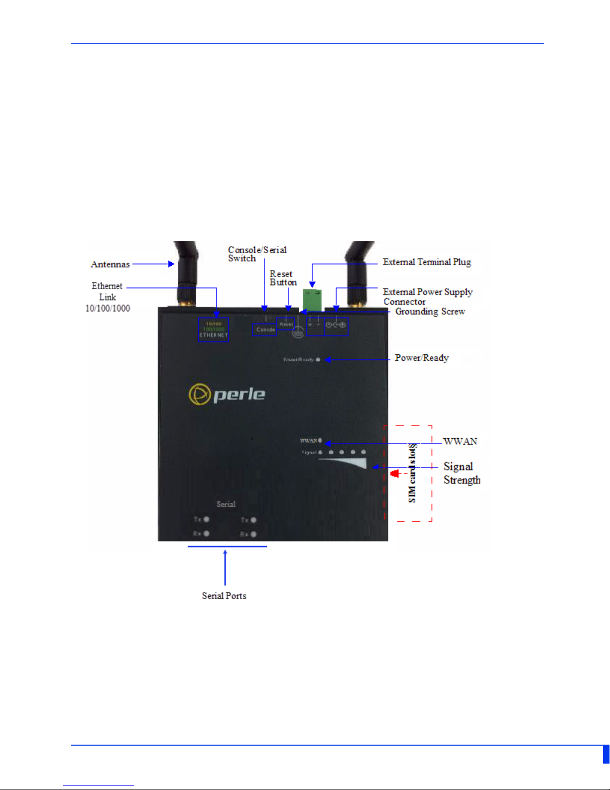
IOLAN SDS2 L
IOLAN SDS2 LA/LE Hardware Installation Guide
Page 6
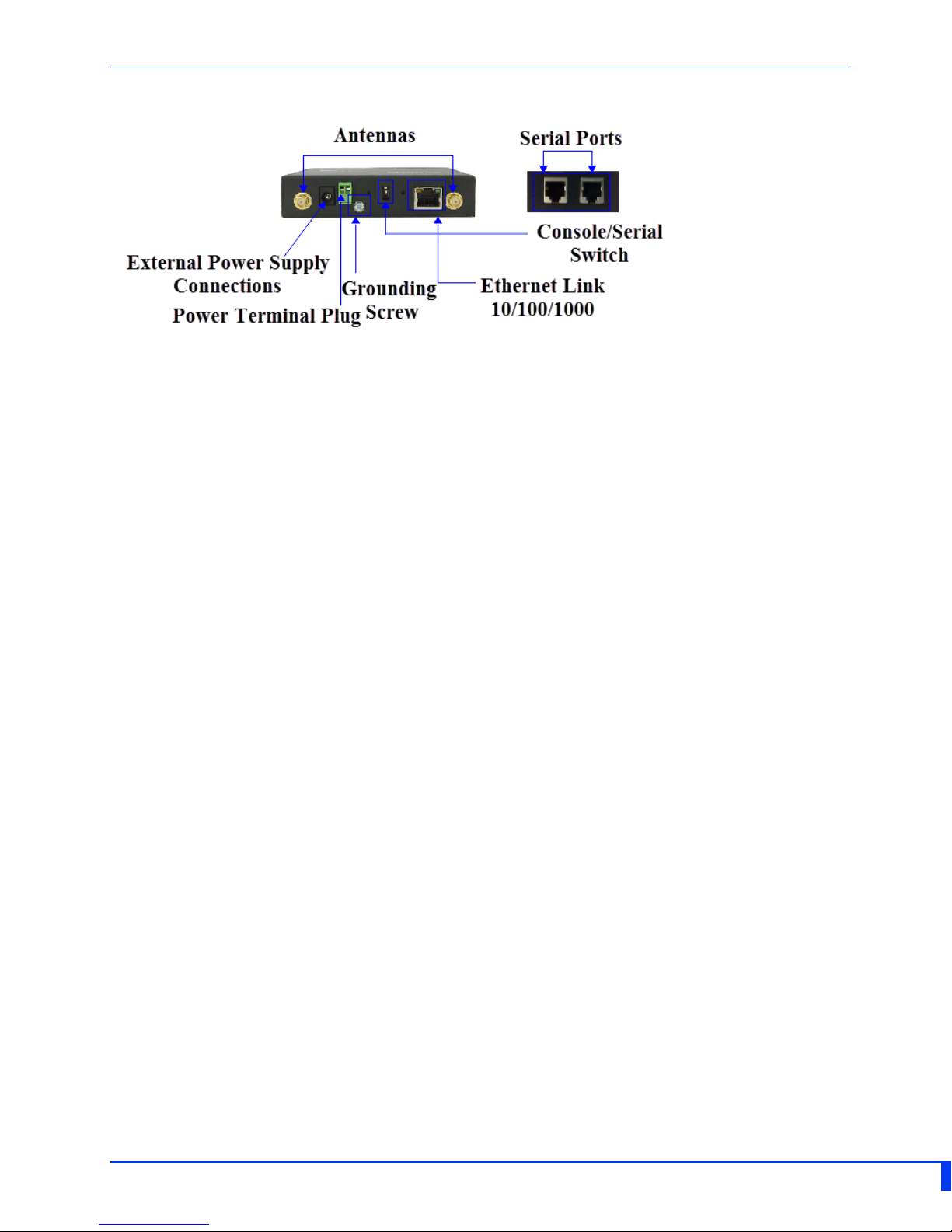
IOLAN SDS2 L (Back View)
Ethernet and Serial Port
10/100/1000Base-T Port
The Ethernet port provides the standard gigabit Ethernet interface speeds of 10/100/
1000 Mbps through twisted pair (UTP) cables of up to 100 meters (328ft) in length.
RJ-45 Console Port
The dip switch on the IOLAN is set in the factory to serial (down position). Unless you
plan to attach a console to the IOLAN, leave the dip switch in the serial position. This is a
console management port providing access to the IOLAN management function using the
industry standard CLI command set. See Connecting the Console Port.
Button/Switch Functions
Reset Button
To reboot the IOLAN SDS2 L insert a paper clip into the inset hole labeled as Reset and
gently press inwards and release. The Power/Ready LEDs on the IOLAN SDS2 L will go On
and then momentarily Off when released to show that the unit has been rebooted. All
links will be dropped and the MAC tables will be cleared.
IOLAN SDS2 LA/LE Hardware Installation Guide
Page 7
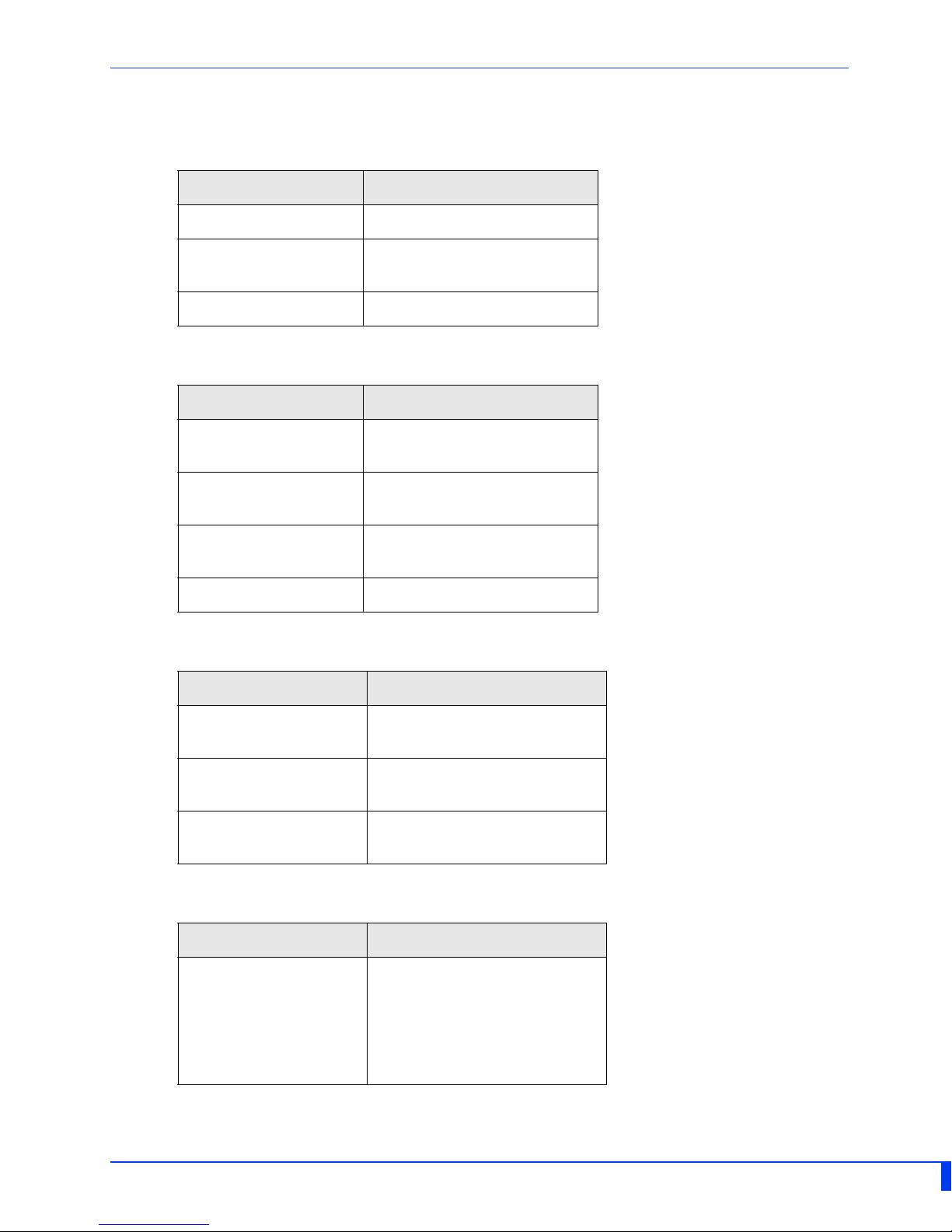
LED Indicators
Power/Ready
State Description
Green - solid System Ready
Green - flashing System is booting or dip
Off Error condition
Link 10/100/1000
State Description
Green 1000 Mbps (flashes with
switch is in console mode
activity)
Green/Orange 100 Mbps (flashes with
Orange 10 Mbps (flashes with
Off No LAN connection
WWAN
State Description
Green-solid A wireless connection has
Green-flashing Data is being transmitted
Off No wireless connection
Signal strength
State Description
activity)
activity)
been established / activity
over the wireless network
established
2 X Orange/
3 X Green
This is a progressive signal. If
only the orange LEDs are lit,
this would indicate a weak
signal. Advancement of
green LEDs indicate a
stronger signal strength
IOLAN SDS2 LA/LE Hardware Installation Guide
Page 8
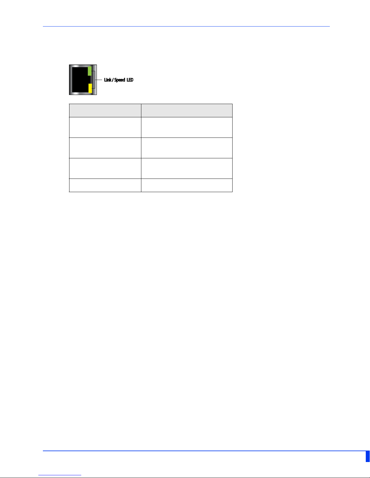
Ethernet Port Status Indicators
Port Link / Speed (Green, Amber and Yellow LEDs)
State Description
Green 1000 Mbps (flashes with
activity)
Green/Orange 100 Mbps (flashes with
activity)
Orange 10 Mbps (flashes with
activity)
Off No LAN connection
IOLAN SDS2 LA/LE Hardware Installation Guide
Page 9

Installation
This chapter discusses the following topics:
General Cautions and Warnings
Connecting the Console Port
Connecting Data Ports
Resetting the Switch
Configuring the IOLAN
General Cautions and Warnings
Warning: Power sources must be off prior to beginning the power connection steps.
Read the installation instructions before you connect the unit to its power source.
Warning: Ensure that the voltage and current ratings of the intended power source are
appropriate for the IOLAN as indicated on the product label.
Warning: Ensure that the installation and electrical wiring of the equipment is performed
by trained and qualified personnel and that the installation complies with all local and
national electrical codes.
Warning: The working voltage inputs are designed for operation with Safety extra low
Voltage (SELV). Connect only to SELV circuits with voltage restrictions in line with IEC/EN
60950‐1:2005 (2nd Edition) + A1:2009 and EN 60950‐1: 2006 + A11:2009
Warning: If this equipment is used in a manner not specified by the manufacturer, the
protection provided by the equipment may be impaired.
Warning: Transient protection shall be provided that is set at a level not exceeding 140%
of the peak rated voltage value at the supply terminals to the equipment.
IOLAN SDS2 LA/LE Hardware Installation Guide
Page 10
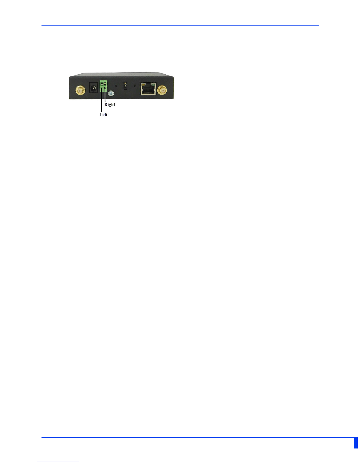
Connecting the Hardware
Terminal block connector
Either the barrel or TB (Terminal Block) can be used to power the SDS2 L.
Plug the power adapter into a power socket and connect the barrel connector end into
the IOLAN SDS2 L. The IOLAN SDS2 L will perform a power up sequence. The Power/
Ready LED should show a solid green. See LED Indicators for power up sequence.
Connecting the terminal block connector
1. Ensure power is NOT applied to the wires prior to connection.
2. On each end wire (12‐20 AWG), remove the insulation from the copper wire 5 mm (3/
16 of an inch).
3. Loosen the left screw on the top of the terminal connector block, then insert your
positive (+) wire into the left terminal and screw it down tight (.51Nm torque).
Loosen the right screw on the top of the terminal connector block, then insert your
negative (‐) wire into the right terminal and screw it down tight (.51Nm torque).
4. Re‐insert the terminal block connector if removed.
5. Connect the Wi‐Fi antenna/s by simply screwing the antenna/s onto the connectors
on the IOLAN.
6. Connect the Ethernet cable from the RJ‐45 plug (10/100/1000) to the HUB or switch
that will provide network connectivity (if applicable to your application).
7. The console dip switch on the IOLAN should be set to the down position for serial
mode.
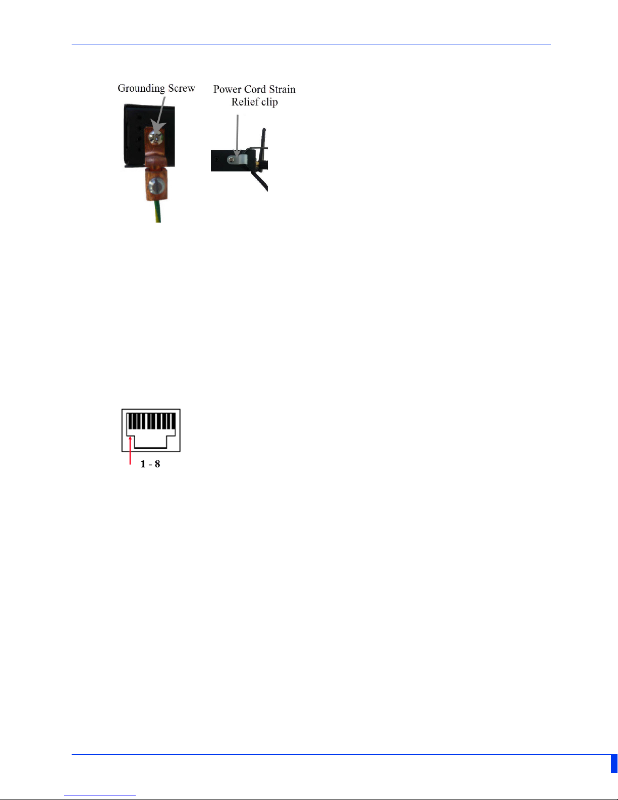
8. Connect the power cord strain relief, if desired. (Figure 2)
9. Connect the grounding lug (not provided) to the grounding screw, if desired. (Figure
1)
10. Turn on power at source. See LED Indicators for power up sequence.
Grounding and Power Cord Relief clip
If your installation requires additional grounding, follow this procedure.
Grounding the chassis requires the following items:
• One grounding lug (not provided)
• One 12AWG wire (not provided)
Follow the manufacturers instructions for attaching the ground wire to the grounding
lug.
1. Attach the grounding lug to the chassis and secure with the grounding screw
provided. See Figure 1.
2. Attach the power cord relief clip as shown in Figure 2.
IOLAN SDS2 LA/LE Hardware Installation Guide
Page 11
Connecting the Console Port
Figure 1
Figure 2
The IOLAN SDS2 L can be fully configured and managed from the console port. The IOLAN
is set in the factory to serial (down position). Serial port 1 is used as the console port if
the DIP switch is set to the up position. Unless you plan to attach a console to the IOLAN,
leave the dip switch in the serial position. This is a console management port providing
access to the IOLAN management function using the industry standard CLI command set.
See the IOLAN Command Line Interface Reference Guide.
Console Port
The console port is an 8‐pin male connector (with DTE pinouts).
1. Connect the appropriate cable directly from the IOLAN SDS2 LA/LE to the COM port
2. Choose Start > Control Panel > Systems or equivalent on the Wi n d o w s O p e r a t i n g S y s ‐
3. Click the Hardware tab and choose Device Manager, Expand the Ports (COM & LPT)
4. Start an terminal‐emulation program (such as Putty or SecureCRT) on the COM port
5. Configure this COM port within the terminal emulation program with the following
6. Connect power to the unit as described in Connecting Power to the IOLAN SDS2 L.
7. The PC will display the boot‐loader sequence.
on your PC. An adapter kit can be ordered from Perle.
tem you are using.
section. This will expand the drop down to show the number of com ports on your
system. Connect the cable to one of these ports (probably com1 or com2).
where you have connected the cable PC.
parameters:
• 9600 baud
• 8 data bits
• 1 stop bit
• No parity
• None (flow control)
IOLAN SDS2 LA/LE Hardware Installation Guide
Page 12
Connecting Data Ports
Ethernet Connection
By default the 10/100/1000 Ethernet port will automatically set itself up to match the
speed of the port it is connected to. If auto negotiation is not supported by that port
then, the port can be configured to operate at a fixed speed and duplex settings.
To connect to 10Base-T, 100Base-TX or 1000Base-T follow these steps:
1. Connect a straight through Ethernet cable from the IOLAN SDS2 L Ethernet port to an
10/100/1000 RJ45 port on the network hub/switch.
2. Once the IOLAN SDS2 L is connected and the link is established, the link LEDs will turn
on. These LEDs will indicate whether you have a 10, 100 or 1000 Mb/s link to your
hub/switch. See. (LED Indicators) for more details.
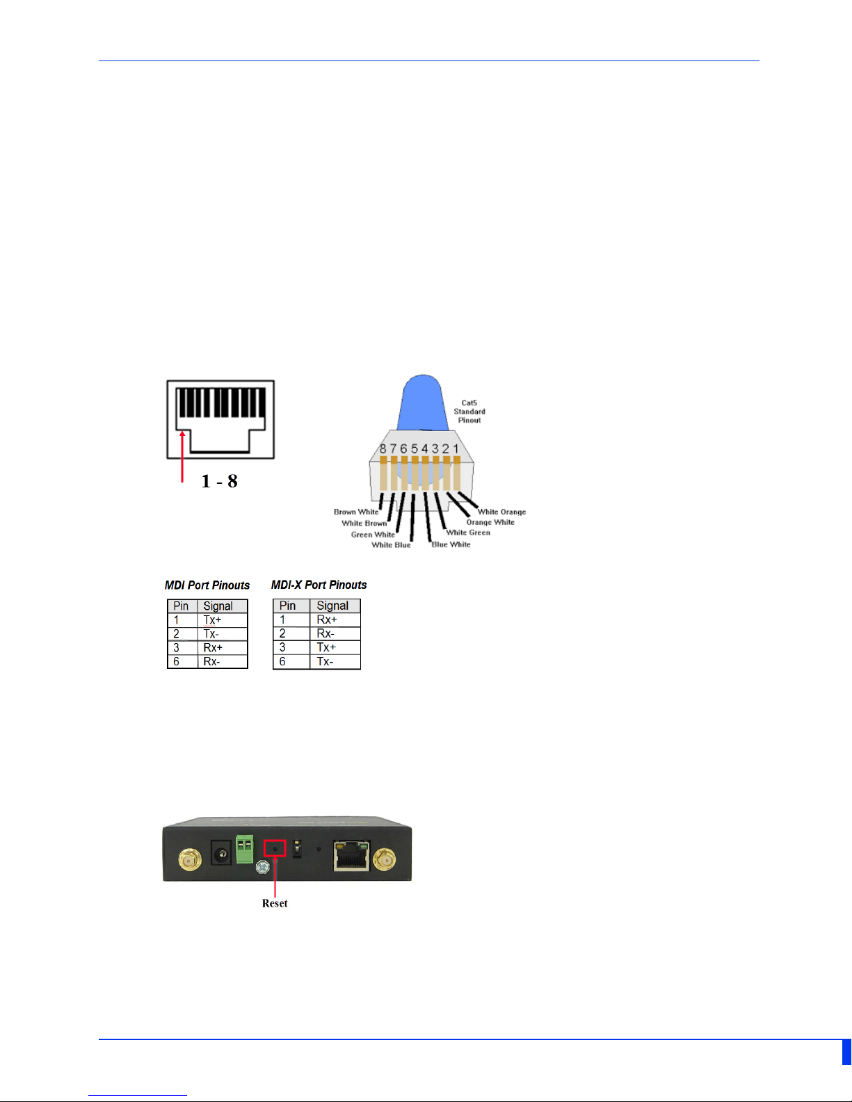
Ethernet Connector - 8-pin RJ-45
Resetting the Switch
To reset the IOLAN insert a paper clip into the inset hole labelled as Reset and gently
press inwards. The Power/Ready LEDs on the IOLAN SDS2 L will go On and then
momentarily Off when released to show that the unit has been reset. All links will be
dropped and the MAC tables will be cleared.
Reset to Factory Default Configuration
To reset the IOLAN insert a paper clip into the inset hole labelled as Reset and gently
press inwards. If you hold the reset button between 3 and 10 seconds, the IOLAN SDS2 L
IOLAN SDS2 LA/LE Hardware Installation Guide
Page 13

will reset the configuration to factory default (either the Perle or custom default configu‐
ration). If you hold the reset button greater than 10 seconds, then the IOLAN SDS2 L will
reset the configuration to the Perle factory default configuration.The Power/Ready LEDs
on the IOLAN SDS2 L will go On and then momentarily Off when released to show that
the unit has been reset. All links will be dropped and the MAC tables will be cleared.
Configuring the IOLAN
The IOLAN can be configured, operated and monitored using any of the following
methods. See the IOLAN User’s Guide for more details.
CLI
A text‐based Command Line Interface based on industry standard syntax and structure.
The CLI can be accessed from the console port without a valid IP address for the initial
setup. Once an IP address has been assigned the IOAN can also be accessed by Telnet,
SSH, SNMP or the Web interface.
Web Device Manager
The Perle Web Device Manager is an embedded Web based application that provides an
easy to use browser interface for configuring and managing the IOLAN. The IOLAN SDS2 L
can be accessed through any standard desktop web browser. The IOLAN must have a
valid IP address.
DeviceManager
This utility provides the ability to do either an initial setup (out of the box) or to configure
and manage the IOLAN. In order to use this utility the IOLAN must be connected to your
network.
For more information on configuring your IOLAN SDS2 L, see the IOLAN User’s Guide.
IOLAN SDS2 LA/LE Hardware Installation Guide
Page 14
Appendix A - Technical Specifications
IOLAN SDS2 L Technical Specifications
SDS2 L
-40°C to 75°C
Operating Temperature
Storage Temperature
Operating and Storage
Humidity 5 to 95% (non condensing)
Weight 0.4 Kg (0.88lbs)
-40°F to 167°F
-40°C to 85°C
-40°F to 185°F
Dimensions
Contacting Technical Support
Contact information for the Perle Technical Assistance Center (PTAC) can be found at the
link below.
https://www.perle.com/support_services/support_request.shtm
Warranty / Registration
This product is covered by the Perle IOLAN SDS Warranty. Details can be found at:
https://www.perle.com/support_services/warranty.shtml
110 by 111 by 24 mm
4.3 by 4.4 by 0.9 in
.
IOLAN SDS2 LA/LE Hardware Installation Guide
Page 15
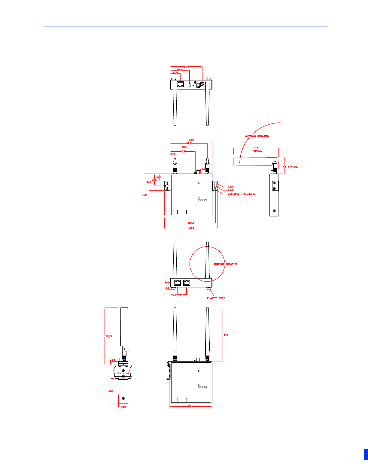
Appendix B - Mechanical Drawing
IOLAN SDS2 LA/LE Hardware Installation Guide
Page 16
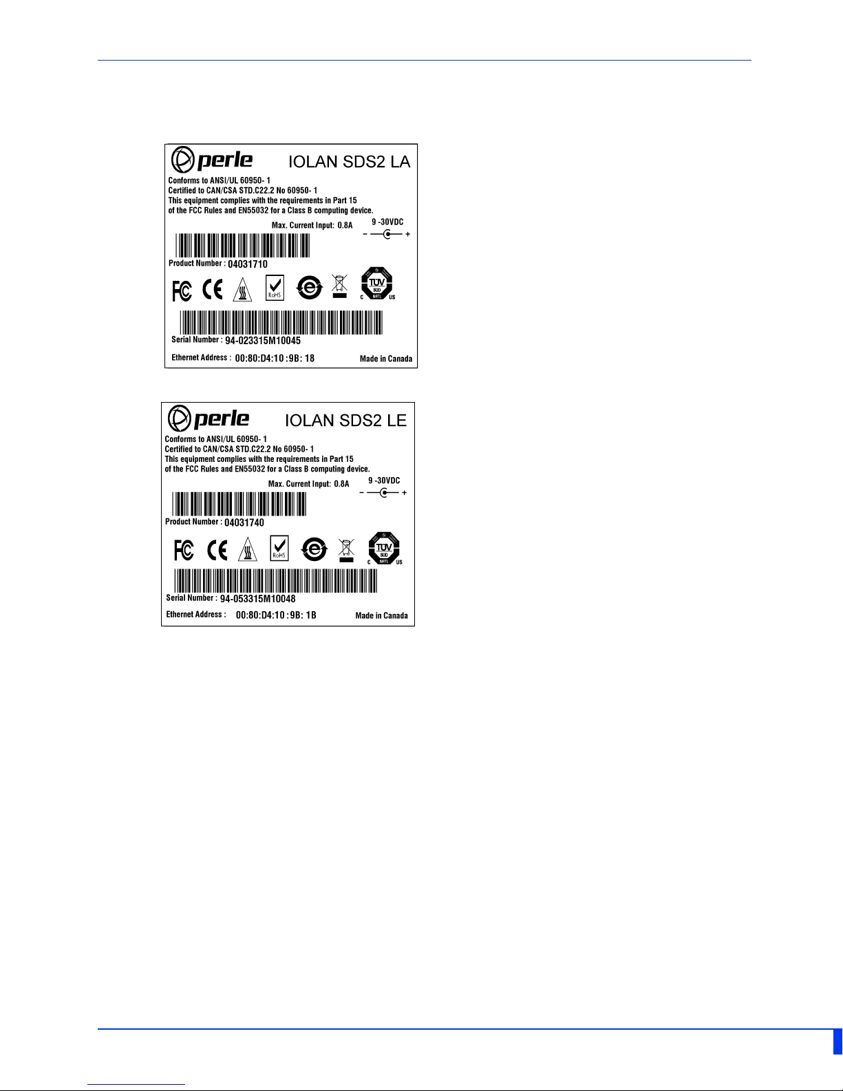
Appendix C - Sample Label
IOLAN SDS2 LA/LE Hardware Installation Guide
Page 17
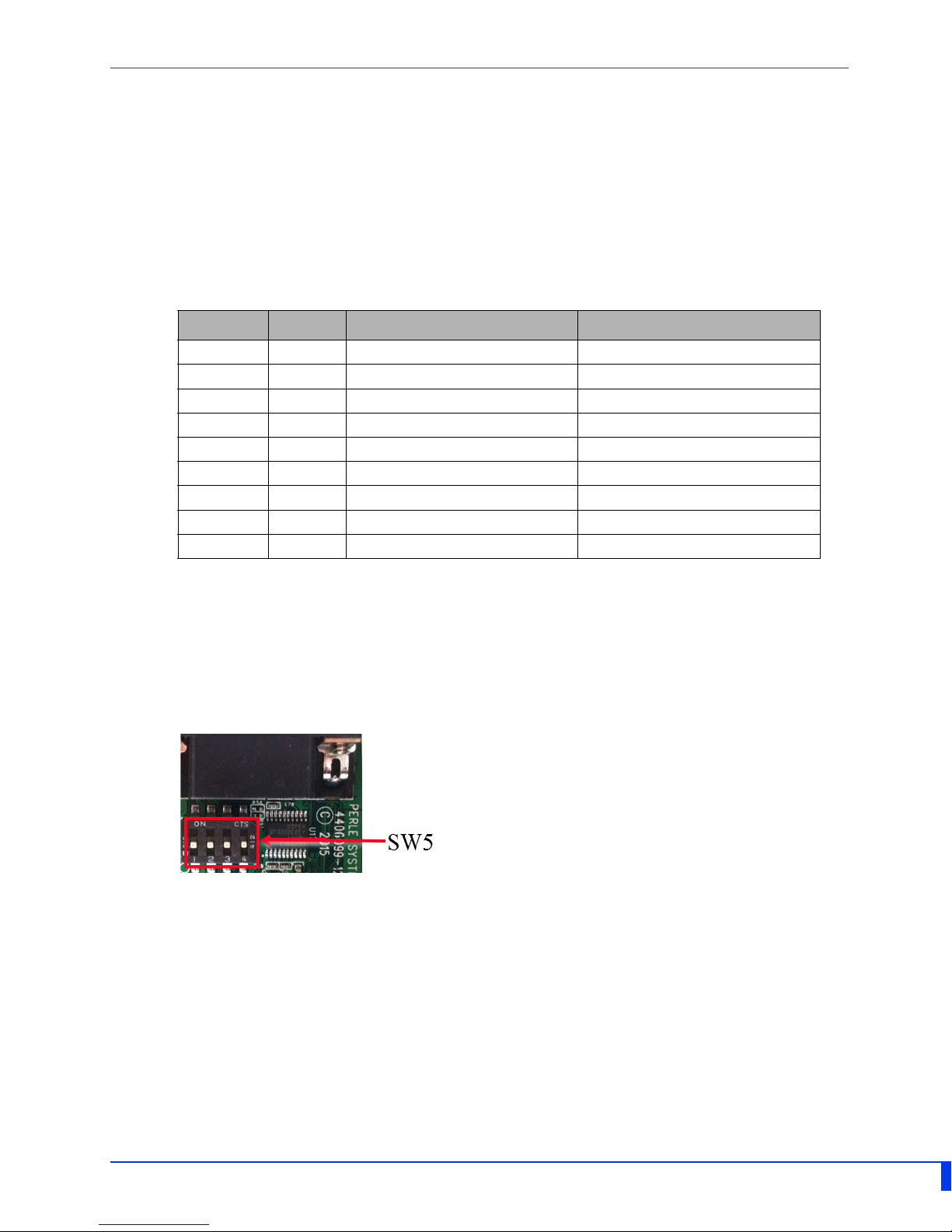
Switch pair one and two used for Serial port 1
Switch pair three and four used for Serial port 2
Appendix D - Cabling and Connectors
This appendix provides pinouts for the serial RJ45 port and the Ethernet cable.
A Starter Kit (optional) can be purchased from https://www.perle.com/products.shtml.
The serial port can operate in either EIA 232, 422 or 485 mode. This is a software config‐
uration. If EIA 422 or 485 is selected, the line termination may need to be set. SW5 has
two switches associated with the serial port. See Figure 3.
RJ45 Socket Pinouts
Pinout RS232 EIA 422/485 Full Duplex RS485 Half Duplex
1 (out) DCD ‐ ‐
2 (out) RxD RxD+
3 (in) TxD TxD‐ TxD‐/RxD‐
4 (in) DTR
5 GND GND GND
6 (out) DSR ‐
7 RTS TxD+ TxD+/RxD+
8 (out) CTS RxD‐ ‐
9
‐
‐‐
‐
Terminating 485/Full/Half and 422 Mode
When in 485/full/half or 422 mode, termination is not necessary unless the IOLAN’s are
the end points.
Remove the screws from the case and gently lift the top section of the case from the
bottom section. Locate SW 5 on the board.
Set ‐ RX Termination: First Switch of Pair ON (used for 422/485 half duplex)
Set ‐ TX Termination: Second Switch of Pair ON (used for 485 full duplex).
Note: For EIA‐232 these switches must be in the OFF position (default)
Ethernet Cable
The 10/100/1000BaseT(X) port is located on the back of the IOLAN SDS2 L. This Ethernet
port will automatically adjust depending on the type of Ethernet cable used (straight‐
through or cross‐over), and the type of device (NIC‐type or HUB/Switch‐type) connected
to the port.
Requirements:
• Cat 5 UTP or STP, Cat 5e cables
• 24‐22 AWG (0.20mm2 ‐ 0.33mm2)
• Straight through or Ethernet Crossover cable
IOLAN SDS2 LA/LE Hardware Installation Guide
Page 18

Appendix E - IOLAN Maintenance
• Ensure there is clearance of 50.8mm (2 inches) on all sides of the IOLAN SDS2 L to
provide proper airflow through the unit
• Do not use solvents or cleaning agents on this unit
• Keep vent holes clear of debris
• If case gets dirty wipe with a dry cloth
• Ensure all cables are in good working condition and replace any frayed cables or
cables without clips
IOLAN SDS2 LA/LE Hardware Installation Guide
Page 19
Appendix F - DIN Rail Mounting
A optional DIN Rail can be purchased for this product.
This appendix provides instructions on the following:
• Mounting the IOLAN on a DIN Rail
• Removing the IOLAN from the DIN Rail
Mounting the IOLAN on a DIN Rail
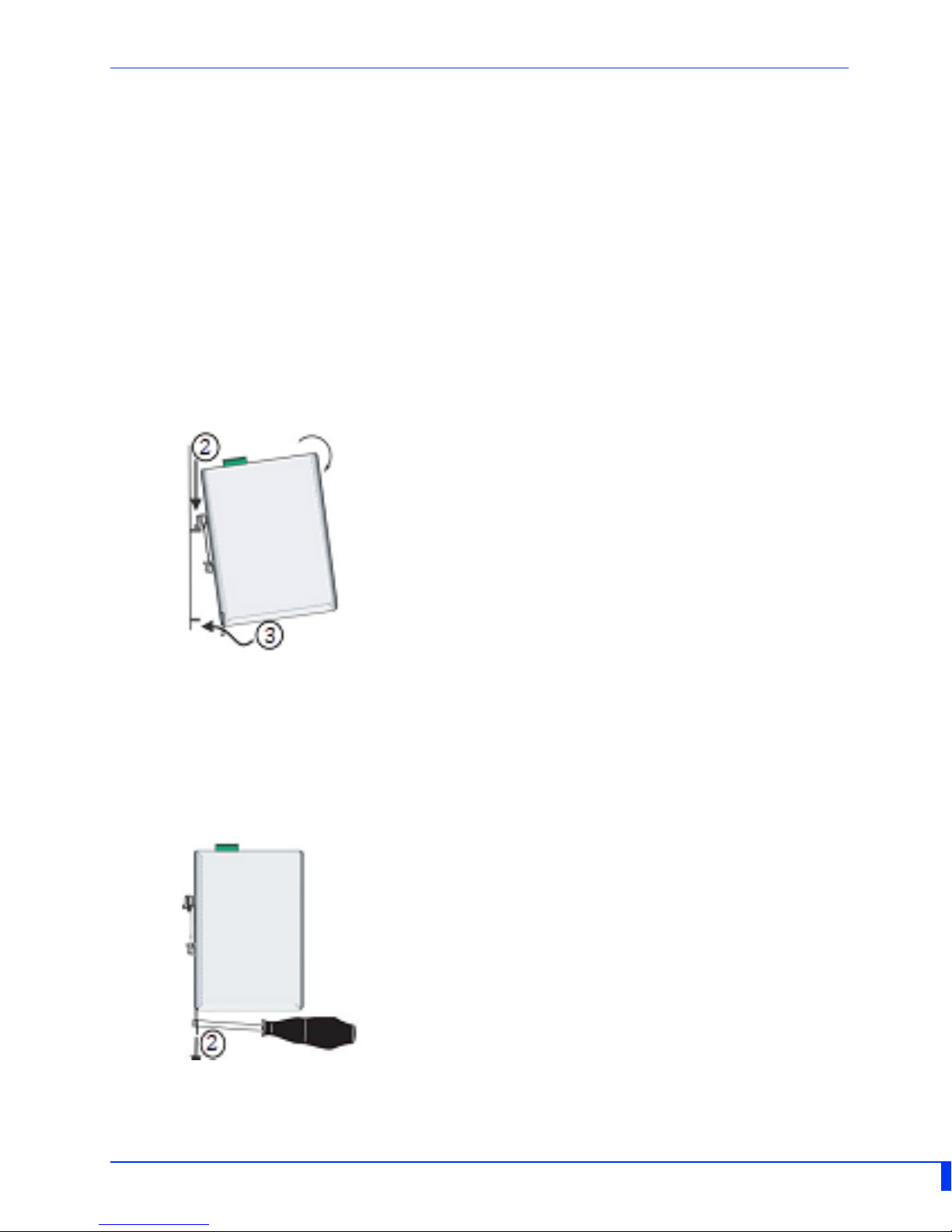
1. Screw the DIN rail clip to the back of the IOLAN.
2. Position the IOLAN so that the top hooks of the DIN rail clip attach onto the top of the
DIN rail.
3. Rotate the bottom of the IOLAN towards the rail. This will snap the bottom hooks of
the DIN rail clip onto the bottom of the DIN rail.
See diagram below.
Removing the IOLAN from the DIN Rail
1. The DIN rail attachment clip has a slot at the bottom of the latch that is visible
beneath the IOLAN when it is mounted.
2. Insert a flat blade screwdriver into the slot and twist the base to release the clip. Alter‐
natively a downward force on the clip will release the clip.
3. When the clip is released, pull the bottom of the IOLAN out slightly and remove the
IOLAN from the DIN rail.
IOLAN SDS2 LA/LE Hardware Installation Guide
 Loading...