

Page 1

IOLAN DS1 G/DS1T G/SDS1 G/SDS1T G Quick Start Guide- P/N 5500417-10 (Rev B)
IOLAN DS1 G/DS1T G
SDS1G/SDS1T G
Quick Start Guide
______________________________________________________________
The DS1/DS1T/SDS1/SDS1T G models provide Serial to Ethernet connectivity.
Leading edge features include; universal software selectable EIA 232/422/485
interface, next generation IP support (IPV6) and 10/100/1000 Ethernet speeds.
This guide covers basic installation and configuration and is intended for first time
setup or product evaluation.
Complete details can be found in the following guides at
www.perle.com/downloads.
• IOLAN User’s Guide
• IOLAN Command Line Interface Reference Guide
• IOLAN DS1 G/DS1T G/SDS1 G/SDS1T G Hardware Installation Guide
What’s in the box?
The IOLAN
• DS1-GR - 1 port with one RJ45 serial port
• DS1T-GR - 1 port with Extended Temperature RJ45 serial port
• DS1-G9 - 1 port with one DB9M serial port
• DS1T-G9 - 1 port (Extended Temperature) with one DB9M serial port
• DS1-G25F - 1 port with one DB25F serial port
• SDS1-GR - 1 port with one RJ45 serial port
• SDS1-G9 - 1 port with one DB9M serial port
• SDS1T-G9 - 1 port (Extended Temperature) with one DB9M serial port
• SDS1-G25F - 1 port with a DB25F serial port
External power supply
A Quick Start Guide (this document)
RJ45-DB9 adapter (RJ45 models only)
Power adapter, strain relief strap and rubber feet
Wall mount brackets
Page 2
IOLAN DS1 G/DS1T G/SDS1 G/SDS1T G Quick Start Guide- P/N 5500417-10 (Rev B)
2
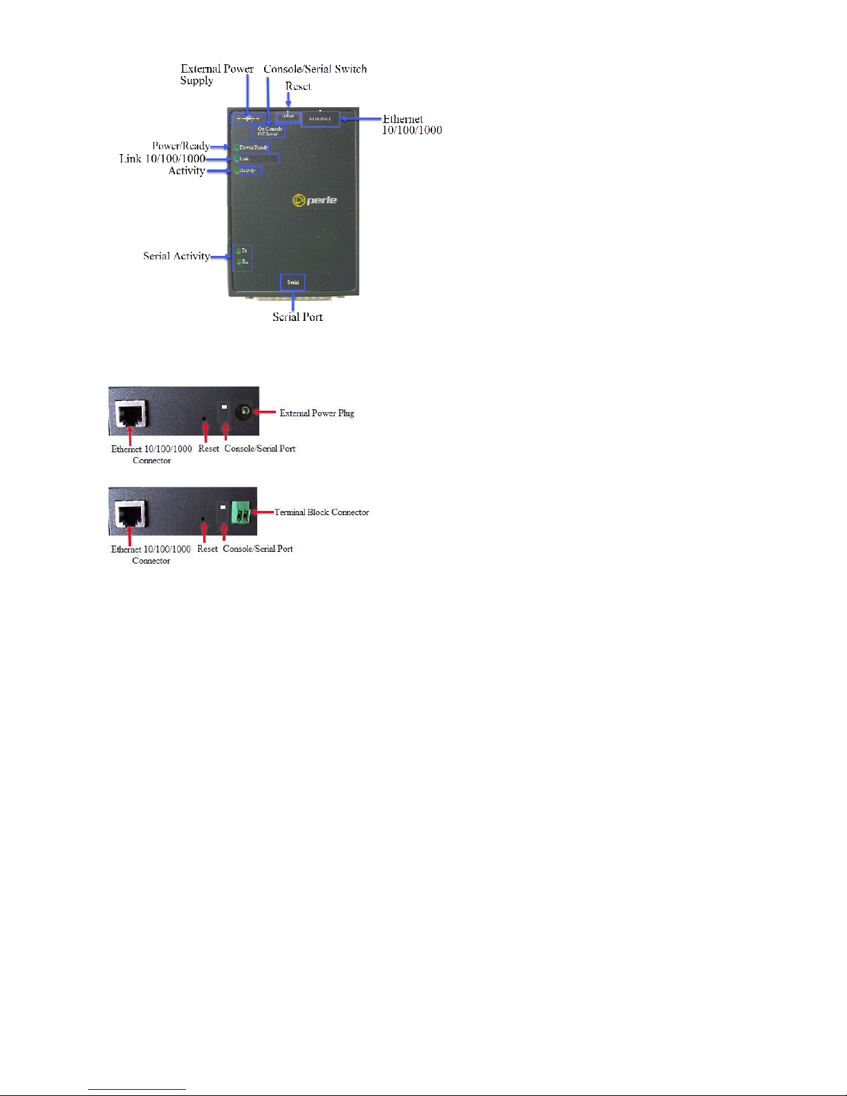
Hardware Overview
Note: The Serial Port can be either RJ45, DB9M or DB25F
Back View DS1 G or SDS1 G with connector for Barrel Connection
Back View DS1T G or SDS1T G with connector for Terminal Connection
Button/Switch Functions
Reset Button
The inset RESET button will reboot the IOLAN if pushed in and released quickly. It
will reset the IOLAN to factory defaults if pushed in and held for more than three
seconds
Console/Serial Switch
The IOLAN is set in the factory to serial (down position). Unless you plan to attach a
console to the IOLAN, leave the dip switch in the serial position. If this DIP switch is
set to the up position, then the serial port is in console mode. In console mode, the
port provides access to the IOLAN management function using the industry
standard CLI command set. See the IOLAN Command Line Interface Reference
Guide.
Connecting the Hardware
Connecting the barrel connector
Plug the barrel connector end into the IOLAN, then plug the power adapter into a
power source. The Power/Ready LED should show a solid green after the boot
sequence.
Page 3

IOLAN DS1 G/DS1T G/SDS1 G/SDS1T G Quick Start Guide- P/N 5500417-10 (Rev B)
3
Wiring the Terminal Block
1. Ensure power is NOT applied to the wires prior to connection.
2. On each end wire (12-20 AWG), remove the insulation from the copper wire 5
mm (3/16 of an inch).
3. Loosen the left screw on the top of the terminal connector block, then insert
your positive (+) wire into the left terminal and screw it down tight (.51Nm
torque). Loosen the right screw on the top of the terminal connector block,
then insert your negative (-) wire into the right terminal and screw it down
tight (.51Nm torque).
4. Turn on power at source.
5. Connect the Ethernet cable from the RJ-45 plug (10/100/1000) to the HUB or
switch that will provide network connectivity (if applicable to your
application).
6. The console dip switch on the IOLAN should be set to the up position for
serial mode.
7. Connect the power cord strain relief and the grounding lug, if desired. See
IOLAN DS G/DS1T G/SDS1 G/SDS1T G Hardware Installation Guide for details.
Power On Cycle
When the power is connected to the IOLAN, the Power/Ready LED will cycle
through several sequences and will end in a solid green once the unit is fully
booted and ready to be configured. If the LED is not solid green after two minutes,
see the DS1 G/DS1T G/SDS1 G/SDS1T G Hardware Installation Guide.
LED Guide
System Ready
• Green Solid—System Ready
• Flashing—System is booting or DIP switch is in console mode
• Yellow—Flashing—Booting
• Red—Error condition. See IOLAN DS1 G/DS1T G/SDS1 G/SDS1T G
Hardware Installation Guide
Page 4

IOLAN DS1 G/DS1T G/SDS1 G/SDS1T G Quick Start Guide- P/N 5500417-10 (Rev B)
4
Link 10/100/1000
• Green—1000 Mbps (flashes with activity)
• Amber—10/100 Mbps (flashes with activity)
• Off—No LAN connection
Serial Activity
• Off—No serial activity
• On—Tx/Rx flashes with transmit/receive serial activity
Connecting Ethernet
Connect the network to the Ethernet port using a Cat5/5e Ethernet cable.
Connecting the Serial Device
Connect the serial device to the IOLAN serial port.
See the IOLAN DS1 G/DS1T G/SDS1 G/SDS1T G Hardware Installation Guide for
pinout details and how to terminate the serial port for 485/Full/Half and 422 mode
if your application requires it.
Configuring the Unit
The IOLAN features several different configuration methods (i.e. HTTP, Telnet,
SNMP) as well as an external Windows based Utility (DeviceManager). For the
most up to date documentation on any of these configuration methods see the
IOLAN User's Guide or for the most recent version of the Device Manager and
other utilities, please refer to the Perle website at www.perle.com
Connecting to the IOLAN
1. Install the DeviceManager to your laptop or PC.
2. Start the DeviceManager program from installed programs.
3. Under the DeviceManager menu, select File, then select Connect to.
4. Your IOLAN will show as Unconfigured in the list.
5. Select your IOLAN from the list and select the Assign IP button.
6. Assign a valid IP address to the IOLQAN that is on your network.
7. You will be prompted by the software for the admin password before being
able to connect and configure the IOLAN (superuser (case sensitive)).
8. You should change the admin password to restrict unauthorized access to the
IOLAN.
Registering and Contacting Technical Support for the IOLAN
You should register IOLAN online at:
www.perle.com/support_services/warranty_reg.asp
Contact information for the Perle Technical Assistance Center (PTAC) can be found
at the link below.
www.perle.com/support_services/support_request.shtm
 Loading...