

Page 1

IOLAN DS Family
SDS/SCS/STS
User’s Guide
Version 2.5
Part #5500161-25
November 2006
Page 2

Copyright Statement
This document must not be reproduced in any way whatsoever, either printed or electronically, without the consent of:
Perle Systems Limited,
60 Renfrew Drive
Markham, ON
Canada
L3R 0E1
Perle reserves the right to make changes without further notice, to any products to improve reliability, function, or
design.
Perle, the Perle logo, and IOLAN are trademarks of Perle Systems Limited.
Microsoft, Windows 98, Windows NT, Windows 2000, Windows Server 2003, Windows XP, and Internet Explorer are
trademarks of Microsoft Corporation.
Netscape is a trademark of Netscape Communications Corporation.
Mozilla Firefox is a trademark of the Mozilla Foundation.
Solaris is a registered trademark of Sun Microsystems, Inc. in the USA and other countries.
Perle Systems Limited, 2005-2006.
FCC Note The IOLAN Device Server has been found to comply with the limits for a Class A digital
device, pursuant to Part 15 of the FCC rules. These limits are designed to provide
reasonable protection against harmful interference when the equipment is operated in a
commercial environment. This equipment generates, uses, and can radiate radio frequency
energy and, if not installed and used in accordance with the instructions in this Guide, may
cause harmful interference to radio communications. Operation of this equipment in a
residential area is likely to cause harmful interference, in which case the user will be
required to correct the interference at his/her own expense.
EN 55022: 1998, Class A, Note
WARNING This is a Class A product. In a domestic environment this product may cause radio interference in which case
the user may be required to take adequate measures.
Caution: the IOLAN Device Server is approved for commercial use only.
WARNING The IOLAN Device Server SDS T models operate in an ambient air temperature above 70 oC. However,
at 70 oC and above, a burn hazard exists if the metal case is touched without proper hand protection.
Page 3

Table of Content s
Preface ...............................................................................23
About This Book ........................................................................ 23
Intended Audience..................................................................... 23
Documentation........................................................................... 23
Typeface Conventions............................................................... 24
Online Help................................................................................. 24
Contacting Technical Support.................................................. 25
Making a Technical Support Query ......................................................25
Who To Contact................................................................................. 25
Have Your Product Information Ready .............................................. 25
Making a support query via the Perle web page................................ 25
Repair Procedure....................................................................................26
Feedback on this Manual....................................................................... 26
Chapter 1 Introduction......................................................27
About the IOLAN Device Server ............................................... 27
IOLAN Device Server Models.................................................... 27
Device Server Features............................................................. 28
Hardware................................................................................................. 28
Software .................................................................................................. 28
Security ...................................................................................................29
IOLAN Device Server User’s Guide, Version 2.5 3
Page 4

Table of Contents
Supported Products/Versions...................................................29
Web Browsers.........................................................................................29
SNTP ........................................................................................................29
SSH...........................................................................................................30
Typical Applications Summary .................................................30
Managing the Device Server..................................................................30
Managing/Accessing devices attached to the Device Server.............30
Network Security.....................................................................................31
Chapter 2 Installation........................................................33
Introduction.................................................................................33
IOLAN Device Server Components...........................................33
What’s Included ......................................................................................33
What You Need to Supply......................................................................33
Available Accessories............................................................................34
Desktop Model Power Supply Requirements.......................................34
Serial Only Models ............................................................................. 34
I/O Models.......................................................................................... 34
Rack Mount DC Power Requirements...................................................34
Electrical Supply Details..................................................................... 34
Connecting DC Power Supply(s) to the Device Server...................... 34
Disconnecting 48V Power Supplies from the Device Server.............. 35
Power Over Ethernet Specifications.....................................................36
Getting to Know Your Device Server........................................36
1-Port........................................................................................................36
2-Port........................................................................................................37
4-Port........................................................................................................37
Rack Mount..............................................................................................38
Console Port/LED View...................................................................... 38
Serial/Ethernet View........................................................................... 38
Installing a Rack Mount Device Server.................................................38
LED Guide................................................................................................39
Desktop Models .................................................................................. 39
Rack Mount Models ............................................................................ 39
Console Mode vs. Serial Mode: Desktop Models ................................40
Dedicated Console Port: Rack Mount Models .....................................40
4 IOLAN Device Server User’s Guide, Version 2.5
Page 5

Table of Contents
Powering Up the Device Server................................................ 40
Serial Only Models ................................................................................. 40
I/O Models ............................................................................................... 41
Setting Jumpers......................................................................... 41
1-Port Device Server DB25 Male/Female.............................................. 41
1-Port Device Server RJ45.....................................................................42
1-Port Device Server RJ45 P (Power Over Ethernet) ..........................42
1-Port Device Server DB9...................................................................... 43
2-Port Device Server SDS1M (Modem)................................................. 43
2-Port Device Server ..............................................................................44
4-Port Desktop Device Server............................................................... 45
Digital I/O Module................................................................................... 46
Analog Input Module..............................................................................47
Wiring I/O Diagrams................................................................... 47
Digital I/O.................................................................................................47
Digital Input Wet Contact ................................................................... 47
Digital Input Dry Contact.................................................................... 48
Digital Output Sink ............................................................................. 48
Digital Output Source......................................................................... 48
Analog Input............................................................................................49
Current............................................................................................... 49
Voltage............................................................................................... 49
Temperature Input..................................................................................49
Thermocouple.................................................................................... 49
RTD 2-Wire........................................................................................ 50
RTD 3-Wire........................................................................................ 50
RTD 4-Wire........................................................................................ 50
Relay Output........................................................................................... 50
Normally Open Contact...................................................................... 50
Normally Closed Contact ................................................................... 51
Setting an Initial IP Address ..................................................... 51
Using DeviceManager............................................................................52
Using a Direct Connection.....................................................................53
Using DHCP/BOOTP...............................................................................54
Using ARP-Ping......................................................................................55
IPv6 Network. .......................................................................................... 55
5
Page 6

Table of Contents
Serial Pinouts..............................................................................56
DB25 Male................................................................................................56
DB25 Female ...........................................................................................57
RJ45 .........................................................................................................58
DB9 Male (Serial Only)............................................................................59
DB9 Male I/O............................................................................................59
Power Over Ethernet Pinouts....................................................60
EIA-232 Cabling Diagrams.........................................................61
Terminal DB25 Connector......................................................................61
DB25 Male.......................................................................................... 61
DB25 Female...................................................................................... 61
RJ45................................................................................................... 62
DB9 Male............................................................................................ 62
Modem DB25 Connector........................................................................63
DB25 Male.......................................................................................... 63
RJ45................................................................................................... 63
DB9 Male............................................................................................ 64
Chapter 3 Configuration Methods ...................................65
Introduction.................................................................................65
DeviceManager ...........................................................................65
WebManager ...............................................................................66
Using the WebManager..........................................................................66
CLI................................................................................................66
Menu ............................................................................................66
Accessing the Menu...............................................................................67
Menu Conventions..................................................................................67
DHCP/BOOTP..............................................................................67
SNMP ...........................................................................................68
Required Support MIBs..........................................................................68
Configuring the Device Server Through the MIB.................................68
IOLAN+ Interface ........................................................................69
6 IOLAN Device Server User’s Guide, Version 2.5
Page 7

Table of Contents
Chapter 4 Configuring the Device Server.......................73
Introduction................................................................................ 73
Configuring the Device Server ................................................. 73
General Device Server Configuration................................................... 73
Authentication ........................................................................................ 73
Device Server Services.......................................................................... 74
TruePort...................................................................................................74
Hardware Configuration.........................................................................75
Ethernet Connection .......................................................................... 75
Serial Connection............................................................................... 75
Other.................................................................................................. 75
Port Buffering .........................................................................................75
Local Port Buffering............................................................................ 76
Remote Port Buffers........................................................................... 76
Modbus Configuration............................................................... 77
Overview.................................................................................................. 77
Configuring a Master Gateway........................................................... 77
Configuring a Slave Gateway............................................................. 77
Modbus Gateway Settings.....................................................................78
Modbus Master Gateway................................................................... 78
Modbus Slave Gateway..................................................................... 78
Modbus Line Settings............................................................................ 79
Modbus Master Settings .................................................................... 79
Modbus Slave Settings ...................................................................... 79
Example Scenario...................................................................................80
Email Notification....................................................................... 82
Machine To Machine Connections........................................... 82
Users Connecting to Serial Devices ........................................ 83
Users Connecting to the LAN................................................... 83
Connecting To the Device Server...................................................... 83
Connecting Through the Device Server............................................. 84
7
Page 8

Table of Contents
Setting Up Lines .........................................................................84
DSLogin...................................................................................................84
Direct/Silent/Reverse Connections.......................................................84
Virtual Modems.......................................................................................85
BIDIR........................................................................................................85
TruePort...................................................................................................85
Signal I/O .................................................................................................85
UDP ..........................................................................................................86
PPP Dial On Demand..............................................................................87
Printers ....................................................................................................88
Remote Printing Using LPD................................................................ 88
Remote Printing Using RCP............................................................... 88
Remote Printing Using Host-Based Print Handling Software............. 88
SSL/TLS...................................................................................................88
Serial Tunnel Settings............................................................................89
Setting Up Users.........................................................................89
User Accounts.........................................................................................89
User Levels..............................................................................................90
Sessions..................................................................................................90
Users Connecting from LAN to Device Server to Serial Device.........90
Easy Port Access Menu ..................................................................... 90
Reverse Sessions and Multisessions................................................. 91
Configuring Network Options ...................................................92
Hosts........................................................................................................92
Gateways.................................................................................................92
RIP............................................................................................................92
RIP for Clients Configuration and Operation...................................... 92
Additional PPP and SLIP Functionality - RIP Packet Exchange ........ 92
DNS/WINS................................................................................................93
Syslog......................................................................................................93
SNMP........................................................................................................93
Configuring Time........................................................................93
Setting the Device Server’s Time..........................................................93
Time Settings ..........................................................................................93
SNTP ........................................................................................................93
8 IOLAN Device Server User’s Guide, Version 2.5
Page 9

Table of Contents
Keys and Certificates ................................................................ 94
SSH.......................................................................................................... 94
Users Logging into the Device Server Using SSH (Reverse)............ 94
Users Passing Through the Device Server Using SSH (Dir/Sil) ........ 95
LDAP........................................................................................................ 95
HTTPS......................................................................................................95
SSL/TLS...................................................................................................95
Language support...................................................................... 96
Loading a Supplied Language ..............................................................96
Translation Guidance............................................................................. 97
Software Upgrades and Language Files.............................................. 97
Downloading Terminal Definitions........................................... 98
Creating Terminal Definition Files........................................................98
TFTP Configuration ................................................................. 100
Resetting Configuration Parameters ..................................... 100
Lost Admin Password............................................................. 100
DHCP/BOOTP........................................................................... 101
DHCP/BOOTP Parameters................................................................... 101
SLIP vs. PPP............................................................................. 102
Creating Custom Applications ............................................... 102
I/O Model Features................................................................... 102
Failsafe Timer ....................................................................................... 102
Alarms ................................................................................................... 103
UDP........................................................................................................103
UDP Unicast Format........................................................................ 103
UDP Unicast Example...................................................................... 104
I/O Modbus Slave..................................................................................104
Modbus Serial Application Connected to the Serial Port ................. 104
Modbus Serial Application Connected to the Network..................... 105
Modbus TCP Application.................................................................. 105
9
Page 10

Table of Contents
Modbus I/O Access...............................................................................105
Function Codes ................................................................................ 105
A4/T4 Registers................................................................................ 106
A4D2/A4R2 Registers ...................................................................... 106
D4/D2R2 Registers........................................................................... 107
Serial Signals.................................................................................... 107
TruePort.................................................................................................108
TruePort/Modbus Combination......................................................... 108
API Over TruePort Only.................................................................... 108
Digital Channels....................................................................................109
Digital Input....................................................................................... 109
Digital Output.................................................................................... 110
Temperature Channels.........................................................................111
Analog Channels...................................................................................112
Relay Channels.....................................................................................113
Serial Signals ........................................................................................113
Calibrating Analog Input......................................................................114
Calibrating Voltage........................................................................... 114
Calibrating Current ........................................................................... 114
Calibrating Temperature Input.............................................................114
Calibrating Thermocouple ................................................................ 114
Calibrating RTD................................................................................ 114
Chapter 5 Using the DeviceManager.............................115
Introduction...............................................................................115
Starting a New Session............................................................115
Managing a Device Server ...................................................................116
Populating the Device Server List .................................................... 116
Assigning a Temporary IP Address to a New Device Server........... 117
Adding/Deleting Static Device Servers............................................. 117
Creating a New Device Server Configuration.....................................118
Opening an Existing Configuration File .............................................118
Connecting to a Device Server................................................118
Managing a Device Server.......................................................119
DeviceManager Work Flow ..................................................................119
Creating/Editing Configuration Files ..................................................119
Working With the Device Server Configuration................................ 119
Working With a Local Configuration File .......................................... 119
10 IOLAN Device Server User’s Guide, Version 2.5
Page 11

Table of Contents
Configuring the Server............................................................ 120
Configuring the Main Server Window................................................. 120
Server............................................................................................... 120
Services ........................................................................................... 121
Configuring Advanced Server Settings.............................................. 122
Configuring Port Buffering..................................................................124
Configuring TruePort Baud.................................................................124
Configuring Authentication................................................................. 125
Local................................................................................................. 125
RADIUS............................................................................................ 126
Kerberos........................................................................................... 127
LDAP................................................................................................ 127
TACACS+ ........................................................................................ 128
SecurID............................................................................................ 129
NIS................................................................................................... 130
Configuring the Hardware ...................................................................130
Configuring the SSH Server................................................................131
SSL/TLS Settings..................................................................................132
Cipher Suite ..................................................................................... 133
Validation Criteria............................................................................. 134
Configuring the Modbus Gateway...................................................... 135
Configuring Server Email Alerts.........................................................136
PCI Configuration................................................................................. 137
Custom App..........................................................................................137
Configuring Lines.................................................................... 138
Advanced Line Settings....................................................................... 140
Service Settings....................................................................................142
DSLogin ........................................................................................... 142
Raw Settings.................................................................................... 143
Telnet Settings................................................................................. 143
BIDIR Settings.................................................................................. 144
Rlogin Settings................................................................................. 145
SLIP Settings ................................................................................... 145
PPP Settings.................................................................................... 147
SSH Client Settings.......................................................................... 152
UDP Settings.................................................................................... 153
VModem Settings............................................................................. 154
SSL/TLS Settings............................................................................. 155
Cipher Suite ..................................................................................... 156
Validation Criteria............................................................................. 157
11
Page 12

Table of Contents
Server Tunnel Settings..................................................................... 158
Client Tunnel Settings ...................................................................... 158
Modbus Slave Settings..................................................................... 159
Modbus Master Settings................................................................... 159
Remote IP Slave Mappings.............................................................. 160
Custom App Settings........................................................................ 161
TruePort Settings.............................................................................. 162
Configuring Line Email Alerts .............................................................163
Packet Forwarding................................................................................164
Copying Line Settings to Another Line(s)..........................................166
Configuring Modems............................................................................166
Configuring I/O .........................................................................167
Global Settings......................................................................................167
Temperature Settings....................................................................... 167
Failsafe Timer Settings..................................................................... 167
Modbus Settings............................................................................... 168
TruePort Settings.............................................................................. 168
UDP Settings.................................................................................... 168
Channels................................................................................................170
Digital Output.................................................................................... 170
Digital Input....................................................................................... 171
Relays............................................................................................... 172
Analog .............................................................................................. 174
Basic Alarm Settings ........................................................................ 175
Advanced Alarm Settings................................................................. 176
Temperature..................................................................................... 177
Configuring Users ....................................................................178
Configuring Line Access......................................................................181
Configuring Sessions...........................................................................182
Configuring the Default User...............................................................182
Configuring the Network..........................................................183
Configuring Hosts.................................................................................183
Configuring SNMP................................................................................184
Configuring TFTP..................................................................................185
Configuring DNS/WINS.........................................................................185
Configuring Gateways..........................................................................186
Configuring Syslog...............................................................................187
Configuring RIP.....................................................................................188
12 IOLAN Device Server User’s Guide, Version 2.5
Page 13

Table of Contents
Configuring Time..................................................................... 189
Configuring Time Settings...................................................................189
Configuring SNTP Settings .................................................................190
Configuring Administration Tasks......................................... 191
Configuring Bootup Files ....................................................................191
Configuring the MOTD File..................................................................192
I/O Status/Control .................................................................... 192
Statistics................................................................................... 193
Tools ......................................................................................... 193
Saving a Configuration To File............................................................193
Getting a Configuration File................................................................193
Configuring Multiple Device Servers..................................................193
Downloading Device Server Firmware............................................... 194
Setting the Device Server’s Date and Time........................................ 195
Rebooting the Device Server...............................................................195
Resetting the Device Server to Factory Defaults .............................. 195
Resetting the SecurID Node Secret....................................................195
Resetting/Killing a Line........................................................................196
Keys and Certificates........................................................................... 197
Custom Files.........................................................................................198
Saving Crashes to a Dump File ....................................................... 198
Downloading Terminal Definitions.................................................... 198
Downloading a Language File.......................................................... 198
Downloading a Custom App File...................................................... 198
I/O Channels..........................................................................................198
Calibrating Analog Channels............................................................ 198
Resetting Calibration Data............................................................... 199
Setting DeviceManager Options .........................................................199
13
Page 14

Table of Contents
Chapter 6 Command Line Interface...............................201
Introduction...............................................................................201
CLI Conventions.......................................................................201
Command Syntax..................................................................................201
Command Shortcuts.............................................................................202
Command Options................................................................................202
Server Commands....................................................................203
Server Commands................................................................................203
Set Console...................................................................................... 203
Set Custom-App............................................................................... 203
Set Port-Buffering............................................................................. 204
Set Server......................................................................................... 205
Set SSL Server................................................................................. 207
Set Service....................................................................................... 208
Show Console .................................................................................. 209
Show Custom-App............................................................................ 209
Show Server..................................................................................... 209
Show Port-Buffering ......................................................................... 209
Show Modbus................................................................................... 209
Hardware Commands...........................................................................210
Set Ethernet...................................................................................... 210
Show Hardware................................................................................ 210
SSH Server Commands........................................................................210
Set SSH-Server................................................................................ 210
Show SSH-Server ............................................................................ 211
SSL/TLS Commands.............................................................................211
Set SSL Server................................................................................. 211
Set SSL Server Cipher-suite ............................................................ 213
Show SSL......................................................................................... 214
Modbus Commands..............................................................................214
Set Modbus Gateway....................................................................... 214
Show Modbus................................................................................... 215
14 IOLAN Device Server User’s Guide, Version 2.5
Page 15

Table of Contents
Authentication Commands..................................................................215
Set Authentication............................................................................ 215
Set Authentication Local .................................................................. 216
Set Authentication Kerberos ............................................................ 216
Set Authentication LDAP.................................................................. 216
Set Authentication NIS..................................................................... 217
Add RADIUS.................................................................................... 217
Delete RADIUS................................................................................ 217
Set Authentication RADIUS ............................................................. 218
Set Authentication TACACS+.......................................................... 218
Set Authentication SecurID.............................................................. 219
Show Authentication ........................................................................ 219
TruePort Baud Commands..................................................................220
Set TruePort Remap-Baud............................................................... 220
Show TruePort................................................................................. 220
Email Commands ................................................................................. 220
Set Email-Alert Server...................................................................... 220
Show Email-Alert Server.................................................................. 221
User Commands ...................................................................... 221
Logged Into the Device Server Commands....................................... 221
Admin............................................................................................... 221
Help.................................................................................................. 221
Kill Line............................................................................................. 221
Kill Session....................................................................................... 221
Logout.............................................................................................. 222
Menu................................................................................................ 222
Ping.................................................................................................. 222
Resume............................................................................................ 222
Rlogin............................................................................................... 222
Screen.............................................................................................. 222
Set Termtype.................................................................................... 223
Set User........................................................................................... 223
Set User Session ............................................................................. 224
Show Line Users.............................................................................. 224
SSH.................................................................................................. 225
Syslog Console................................................................................ 226
Show Sessions................................................................................. 226
Show Termtype................................................................................ 226
Start.................................................................................................. 226
Telnet............................................................................................... 227
Version............................................................................................. 228
15
Page 16

Table of Contents
Configuring Users.................................................................................228
Add User........................................................................................... 228
Delete User....................................................................................... 228
Set Default User............................................................................... 228
Set User............................................................................................ 232
Set User Session.............................................................................. 236
Show Default User............................................................................ 236
Show User........................................................................................ 236
Line Commands........................................................................237
1-Port vs. 2-Port+ Line Commands.....................................................237
Line Commands....................................................................................237
Set Line ............................................................................................ 237
Set Line Interface ............................................................................. 241
Set Line Service ............................................................................... 242
Set Modem....................................................................................... 244
Set Termtype.................................................................................... 245
Show Line......................................................................................... 245
Line Service Commands......................................................................245
Set Custom-App............................................................................... 245
Set Rlogin-Client............................................................................... 245
Set Telnet-Client............................................................................... 246
Set SSH-Client ................................................................................. 247
Set PPP............................................................................................ 248
Set SLIP ........................................................................................... 252
Set UDP............................................................................................ 253
Set Vmodem..................................................................................... 254
Set SSL Line..................................................................................... 255
Set SSL Line Cipher-suite................................................................ 256
Set Modbus-Slave Line .................................................................... 257
Set Modbus-Master Line .................................................................. 258
Show Custom-App............................................................................ 258
Show Interface.................................................................................. 259
Show PPP ........................................................................................ 259
Show Rlogin-Client........................................................................... 259
Show SLIP........................................................................................ 259
Show SSH-Client.............................................................................. 259
Show Telnet-Client........................................................................... 259
Show Modbus................................................................................... 259
Show UDP........................................................................................ 259
Show Vmodem................................................................................. 259
16 IOLAN Device Server User’s Guide, Version 2.5
Page 17

Table of Contents
Modem Commands .............................................................................. 260
Add Modem...................................................................................... 260
Delete Modem.................................................................................. 260
Set Modem....................................................................................... 260
Show Modems ................................................................................. 260
Email Commands ................................................................................. 261
Set Email-Alert Line ......................................................................... 261
Show Email-Alert Line...................................................................... 261
Packet Forwarding Commands...........................................................262
Set Packet-Forwarding Line............................................................. 262
Show Packet-Forwarding Line......................................................... 264
Network Commands ................................................................ 264
SNMP Commands.................................................................................264
Add Community................................................................................ 264
Add Trap .......................................................................................... 264
Delete Community............................................................................ 265
Delete Trap ...................................................................................... 265
Set SNMP ........................................................................................ 265
Show SNMP..................................................................................... 265
TFTP Commands..................................................................................266
Set Server TFTP.............................................................................. 266
Hosts Commands.................................................................................266
Add Host .......................................................................................... 266
Delete Host ...................................................................................... 266
Set Host ........................................................................................... 266
Show Hosts...................................................................................... 267
DNS/WINS Commands.........................................................................267
Add DNS.......................................................................................... 267
Add WINS ........................................................................................ 267
Delete DNS...................................................................................... 267
Delete WINS .................................................................................... 267
Show Server..................................................................................... 267
Gateway Commands............................................................................ 268
Add Gateway.................................................................................... 268
Delete Gateway................................................................................ 268
Set Gateway..................................................................................... 269
Show Gateways............................................................................... 269
Logging Commands.............................................................................270
Set Syslog........................................................................................ 270
Show Syslog .................................................................................... 270
17
Page 18

Table of Contents
RIP Commands .....................................................................................271
Add RIP............................................................................................ 271
Delete RIP........................................................................................ 271
Set RIP............................................................................................. 272
Show RIP.......................................................................................... 272
Show RIP Peers............................................................................... 272
Time Commands.......................................................................273
Server Commands................................................................................273
Set Time........................................................................................... 273
Set Timezone ................................................................................... 273
Show Time........................................................................................ 273
Show Timezone................................................................................ 273
SNTP Commands..................................................................................274
Add SNTP......................................................................................... 274
Delete SNTP..................................................................................... 274
Set SNTP.......................................................................................... 275
Show SNTP...................................................................................... 275
Show SNTP-Info............................................................................... 275
Time/Date Setting Commands.............................................................276
Set Date............................................................................................ 276
Set Summertime............................................................................... 276
Set Summertime Fixed..................................................................... 276
Set Summertime Recurring.............................................................. 277
Show Date........................................................................................ 277
Show Summertime........................................................................... 277
Administration Commands......................................................278
Bootup Commands...............................................................................278
Reboot.............................................................................................. 278
Reset................................................................................................ 278
Reset Factory................................................................................... 278
Save ................................................................................................. 278
Set Bootup........................................................................................ 278
Show ARP........................................................................................ 279
Show Bootup.................................................................................... 279
TFTP File Transfer Commands............................................................279
Netload............................................................................................. 279
Netsave ............................................................................................ 280
Keys and Certificates Commands.......................................................280
Netload............................................................................................. 280
Netsave ............................................................................................ 281
18 IOLAN Device Server User’s Guide, Version 2.5
Page 19

Table of Contents
MOTD Commands ................................................................................282
Set MOTD........................................................................................ 282
Show MOTD..................................................................................... 282
Statistic Commands ................................................................ 282
Configuration Statistics.......................................................................282
Show Netstat.................................................................................... 282
Show Netstat Statistics .................................................................... 282
Show Modbus Statistics................................................................... 283
Show Routes.................................................................................... 283
Run-Time Statistics..............................................................................283
Delete Arp........................................................................................ 283
Show Arp.......................................................................................... 283
Show Serial...................................................................................... 283
Uptime.............................................................................................. 283
IOLAN+ User Commands........................................................ 283
IOLAN+............................................................................................ 283
I/O Commands.......................................................................... 284
Global I/O Commands..........................................................................284
Set IO UDP ...................................................................................... 284
Set IO Failsafe ................................................................................. 284
Set IO Modbus................................................................................. 285
Set IO Temperature-Scale............................................................... 285
Set Line..................................................................................................285
Set Line Service............................................................................... 285
Set IOChannel.......................................................................................285
Set IOChannel Mode........................................................................ 285
Set IOChannel Digital I/O................................................................. 286
Set IOChannel Digital Input.............................................................. 286
Set IOChannel Digital Input (Serial Pins)......................................... 287
Set IOChannel Digital Output........................................................... 288
Set IOChannel Digital Output (Serial Pins)...................................... 289
Set IOChannel Relay ....................................................................... 290
Set IOChannel Analog (True Analog) .............................................. 291
Set IOChannel Analog (Temperature) ............................................. 292
Kill IOChannel.................................................................................. 294
Show IO ........................................................................................... 294
Show IOChannel.............................................................................. 295
I/O Channel Control Commands......................................................... 295
Digital Output ................................................................................... 295
Digital Input...................................................................................... 295
Relay................................................................................................ 295
Analog Input..................................................................................... 296
19
Page 20

Table of Contents
Calibrating Analog Input (Analog/Temperature)................................296
Calibrate Analog............................................................................... 296
Reset Calibration.............................................................................. 296
Appendix A RADIUS........................................................297
Introduction...............................................................................297
Supported RADIUS Parameters ..............................................297
Accounting Message................................................................300
Mapped RADIUS Parameters to Device Server Parameters.301
Perle RADIUS Dictionary Example..........................................302
Appendix B TACACS+ ....................................................305
Introduction...............................................................................305
TACACS+ Parameter Values ...................................................305
Direct Users. ..........................................................................................305
Direct User Example Settings..............................................................307
Reverse Users.......................................................................................308
Reverse User Example Settings..........................................................309
Appendix C SSL/TLS Ciphers ........................................311
Introduction...............................................................................311
Valid SSL/TLS Ciphers.............................................................311
Appendix D Troubleshooting.........................................313
Introduction...............................................................................313
Hardware Problems..................................................................313
Communication Issues ............................................................313
DeviceManager Problems........................................................314
Host Problems ..........................................................................314
RADIUS Authentication Problems ..........................................315
20 IOLAN Device Server User’s Guide, Version 2.5
Page 21

Table of Contents
Login Problems........................................................................ 315
Problems with Terminals ........................................................ 315
Unknown IP Address............................................................... 316
DHCP/BOOTP Problems.......................................................... 316
Callback Problems................................................................... 317
Language Problems................................................................. 317
Modem problems ..................................................................... 317
PPP problems........................................................................... 317
Printing Problems.................................................................... 318
Long Reboot Cycle .................................................................. 318
SSL/TLS.................................................................................... 318
I/O Digital or Relay................................................................... 319
Appendix E Utilities.........................................................321
Introduction.............................................................................. 321
TruePort.................................................................................... 321
API I/O Access Over TruePort ................................................ 322
API Request Format............................................................................. 322
API Response Format..........................................................................322
Error Codes...................................................................................... 323
Decoder..................................................................................... 323
21
Page 22

Table of Contents
Appendix F Accessories.................................................325
Introduction...............................................................................325
Installing a Perle PCI Modem Card .........................................325
Starter Kit (Adapters/Cable) ....................................................328
RJ45F to DB25M DTE Crossover Adapter..........................................328
RJ45F to DB25M DCE Modem Adapter...............................................329
RJ45F to DB25F DTE Crossover Adapter...........................................330
RJ45F to DB9M DTE Crossover Adapter............................................331
RJ45F to DB9F DTE Crossover Adapter.............................................332
Sun/Cisco RJ45M Connector Cable for Rack Mount Models ...........332
Glossary...........................................................................333
Index.................................................................................335
22 IOLAN Device Server User’s Guide, Version 2.5
Page 23

Preface
About This Book
This guide provides the information you need to:
z configure the Device Server
z incorporate the Device Server into your production environment
Intended Audience
This guide is for administrators who will be configuring the Device Server.
Some prerequisite knowledge is needed to understand the concepts and examples in this guide:
z If you are using an external authentication application(s), working knowledge of the
authentication application(s).
z Knowledge of TFTP, the transfer protocol the Device Server uses.
Documentation
The following documentation is included on the Device Server installation CD:
z IOLAN Device Server Family Quick Start Guide
z IOLAN Device Server User’s Guide
z TruePort User’s Guide
z TruePort Installation and Configuration Guide for Windows NT
z Online Help in the DeviceManager (automatically installed with the DeviceManager application)
z Link to knowledge base
IOLAN Device Server User’s Guide, Version 2.5 23
Page 24

Typeface Conventions
Typeface Conventions
Most text is presented in the typeface used in this paragraph. Other typefaces are used to help you
identify certain types of information. The other typefaces are:
Typeface Example Usage
At the C: prompt, type:
add host
Set the value to TRUE. The typeface used for TRUE is also used when referring to
subscribe project subject
run yourcode.exec
File, Save This typeface and comma indicates a path you should
IOLAN User’s Guide This typeface indicates a book or document title.
See About the IOLAN Device Server
on page 27 for more information.
Online Help
Online help is provided in the DeviceManager. You can click on the What’s This button ( or )
and then click on a field to get field-level help. Or, you can press the F1 key to get window-level
help. You can also get the User’s Guide online by selecting
This typeface is used for code examples and
system-generated output. It can represent a line you type
in, or a piece of your code, or an example of output.
an actual value or identifier that you should use or that is
used in a code example.
The italicized portion of these examples shows the
typeface used for variables that are placeholders for
values you specify. This is found in regular text and in
code examples as shown. Instead of entering
you enter your own value, such as
for
yourcode, enter the name of your program.
follow through the menus. In this example, you select
Save from the File menu.
This indicates a cross-reference to another chapter or
section that you can click on to jump to that section.
Help, Help Topics.
stock_trader, and
project,
24 IOLAN Device Server User’s Guide, Version 2.5
Page 25

Contacting Technical Support
Making a Technical Support Query
Who To Contact
Contacting Technical Support
Note:
If you bought your product from a registered Perle supplier, you must contact their Technical Support
department; they are qualified to deal with your problem.
Perle offers free technical support to Perle Authorised Distributors and Registered Perle
Resellers.
Have Your Product Information Ready
When you make a technical support enquiry please have the following information ready:
Item Write Details Here
Product Name
Problem Description
Your Name
Company Name and
Address
Country
Phone Number
Fax Number
Email Address
Making a support query via the Perle web page
If you have an internet connection, please send details of your problem to Technical Support using
the email links provided on the Perle web site in the
Click here to access our website at the following URL:
http://www.perle.com
Support/Services area.
25
Page 26

Contacting Technical Support
Repair Procedure
Before sending a Device Server for repair, you must contact your Perle supplier. If, however, you
bought your product directly from Perle you can contact directly.
Customers who are in Europe, Africa or Middle East can submit repair details via a website form.
This form is on the Perle website,
Click here to access our web site at the following URL:
http://www.perle.com/support_services/rma_form.asp
Feedback on this Manual
If you have any comments or suggestions for im proving this manual please email Perle using the
following address:
Email: [email protected]
Please include the title, part number and date of the manual (you can find these on the title page at
the front of this manual).
www.perle.com, in the Support/Services area.
26 IOLAN Device Server User’s Guide, Version 2.5
Page 27

Introduction Chapter 1
1
About the IOLAN Device Server
The Device Server is an Ethernet communications/terminal server that allows serial devices to be
connected directly to LANs. The Device Server can connect to a wide range of devices including:
z T erminals for multi-user UNIX systems
z Data acquisition equipment (manufacturing, laboratory, scanners, etc.)
z Retail point-of-sale equipment (bar coding, registers, etc.)
z PCs using terminal emulation or SLIP/PPP
z Modems for remote access and Internet access
z ISDN adapters for branch remote access and Internet access
z All types of serial printers
The performance and flexibility of the Device Server allows you to use a wide range of high speed
devices in complex application environments. The Device Server will work in any server
environment running TCP/UDP/IP.
IOLAN Device Server Models
The IOLAN Device Server comes in several different models to meet your production environment
needs:
z DS—Offered as a 1-port unit, this model provides basic Device Server functionality. This model
can be ordered with RJ45, DB9 male, DB25 female, or DB25 male connection options. There is
also a line of DS models that support Analog Input, Temperature Input, Relay Output, and/or
Digital I/O.
z TS—The model does everything the DS model does plus has two RJ45 serial ports (supports
EIA-232 only). This model does not support the power out/power in pins or I/O.
z SDS—This model does everything the DS model does plus additional features such as external
authentication, SSH, SSL, port buffering, email alerts, RIP, DNS/WINS, plus much more. This
model has an EIA-232/422/485 switchable interface. Rack mount models have a dedicated
Console port and support gigabit Ethernet. The 1-port model can be ordered with RJ45, DB9
male, DB25 female, or DB25 male connection options. Some SDS models support Power Over
Ethernet or have an internal modem. There is also a line of SDS models that support Analog
Input, Temperature Input, Relay Output, and/or Digital I/O; all models in this line are extended
temperature models, meaning that they can operate in higher temperature environments.
z STS—This model does everything the DS model does plus additional features such as external
authentication, SSH, SSL, port buffering, email alerts, RIP, DNS/WINS, plus much more. This
model has an EIA-232 interface. Rack mount models have a dedicated Console port and support
gigabit Ethernet. Some models support dual input DC power.
IOLAN Device Server User’s Guide, Version 2.5 27
Page 28

Device Server Features
z SCS—This model does everything the DS model does plus additional features such as external
authentication, SSH, SSL, port buffering, email alerts, RIP, DNS/WINS, plus much more. This
model has an EIA-232 interface. Rack mount models have a dedicated Console port. This model
comes equipped with PCI interface (supports the Perle PCI modem card), gigabit support, dual
Ethernet, and can have dual AC power.
Device Server Features
The Device Server is a communications server used for making serial network connections. It
attaches to your TCP/IP network and allows serial devices such as modems, terminals, or printers to
access the LAN. It also allows LAN attached devices to access serial devices attached to the Device
Server.
Hardware
The Device Server hardware features can include (depending on the model):
z Auto sensing 10/100/1000 RJ45 Ethernet interface.
z Universal, software-selectable EIA-232/422/485 interface (the SCS/STS models are only
EIA-232).
z Full modem control using DTR, DSR, CTS, RTS and DCD.
z Tx and Rx activity indicators.
z External AC or DC power supply, or power over serial or Ethernet.
z LEDs for diagnostic testing.
z Self-test on power-up.
z Reset switch.
z PCI modem card.
z Dedicated console.
z Analog Input, Temperature Input, Relay Output, and/or Digital I/O.
Software
The Device Server software features include:
z Multiple ways to configure the Device Server:
– Easy Config Wizard, an easy configuration wizard that allows you to complete basic Device
Server configuration
– DeviceManager, a fully functional Windows 98/NT/2000/ME/Server 2003/XP
configuration/management tool
– WebManager, a web browser option for configuring/managing the Device Server
– Menu, a window-oriented menu interface for configuration and user access
– CLI, a Command Line Interface option for configuration/management and user access
– SNMP, allowing remote configuration via SNMP as well as statistics gatherin g
– DHCP/BOOTP, a method of automatically updating the Device Server
– IOLAN+ interface, for IOLAN+ users, Device Server models with 16 ports or fewer can be
configured using the IOLAN+ menu
z IPv6 support.
z Support for TCP/IP and UDP protocols including telnet, rlogin, and SSH.
z Remote access support including PPP, SLIP, and CSLIP.
z Printer support via LPD and RCP.
z Vi rtual modem emulation.
28 IOLAN Device Server User’s Guide, Version 2.5
Page 29

Security
Supported Products/Versions
z ‘Fixed tty’ support for several operating systems (TruePort).
z DHCP/BOOTP for automated network-based setup.
z Dynamic statistics displays and line status reporting for fast problem diagnosis.
z Multi session support on a single terminal.
z Interoperability with IP routing through gateway tables.
z Domain Name Server (DNS) support.
z WINS support for Windows
®
environments.
The Device Server security features can include (depending on your Device Server model):
z SSH connections.
z SSL connections.
z Supervisory and port (line) password.
z Port locking.
z PPP authentication via PAP or CHAP.
z Per-user access level assignment.
z Logging via Syslog.
z RADIUS accounting.
z Email notification.
z External authentication using any of the following systems:
– RADIUS
– Kerberos
– TACACS+
– NIS
– SecurID
– LDAP
z Trusted host filtering, allowing only those hosts that have been configured in the Device Server
access to the Device Server.
z Idle port timers, which close a connection that has not been active for a specified period of time.
z Ability to individually disable daemons/services that won’t be used by the Device Server.
Supported Products/Versions
Web Browsers
The WebM anager has been tested on Windows and Linux with the following web browsers:
z Netscape—7.x
z Internet Explorer—6.x
z Mozilla Firefox—1.x
SNTP
Versions 1, 2, 3, and 4 are supported. SNTP version must be specified for SNTP configuration.
Introduction 29
Page 30

Typical Applications Summary
SSH
SSH 1 is supported with the following ciphers:
z Blowfish
z 3DES
SSH 2 is supported with the following ciphers:
z 3DES
z Blowfish
z AES (128/192/256-bit)
z CAST128
z Arcfour
Typical Applications Summary
Managing the Device Server
The Device Server can be managed and configured by administrators through various methods,
allowing them full configuration capabilities and easy access to management statistics and tools.
Administrators can access the Device Server using the following methods:
z Connection through Ethernet using the DeviceManager, a Windows-based configuration
application.
z Connection through Ethernet using WebManager, via a web browser.
z Direct connection to the serial port using a Serial Terminal or Terminal Emulation Software.
z From the network through the Ethernet interface using reverse Telnet (Port 23) or reverse SSH
(Port 22).
z Through a serial port configured for PPP/SLIP allowing for remote access (Telnet session)
through a modem.
z Through an SNMP agent, using the Device Server MIB.
Managing/Accessing devices attached to the Device Server
The Device Server can be configured to allow users or administrators to view or manage specific
devices on the Device Server’s serial port across the Ethernet interface using two different methods.
z Direct Connect—users can directly connect to the device on the serial port by Telnet or SSH
(
Line Service must be set to Rev Telnet or Rev SSH) using the Device Server’s configured IP
address and the serial device’s assigned TCP port number.
z Easy Port Access—users can connect to the Device Server using the configured Device Server’s
IP address by reverse Telnet (port number 23) or reverse SSH (port number 22), and are provided
with a device menu displaying the name of the device that the user has access to. This feature
eliminates the need for administrators and users to recall the specific port number associated with
a certain device connected to the Device Server. The user can simply connect to a specific device
based upon the name of the device and then return to the device menu without disconnecting its
initial reverse Telnet or reverse SSH connection.
30 IOLAN Device Server User’s Guide, Version 2.5
Page 31

Network Security
The Device Server provides a comprehensive suite of security features to allow an organization to
implement robust security planning to prevent unauthorized access. These include several external
authentication methods, trusted host filtering, and the ability to disable individual services.
For a secure LAN connection, the Device Server supports SSH version 1 and ver sion 2 protocol.
Remote server connections with SSH protocol uses an encrypted data channel with support for
password and public key authentications.
Typical Applications Summary
Introduction 31
Page 32

Typical Applications Summary
32 IOLAN Device Server User’s Guide, Version 2.5
Page 33

Inst allation Chapter 2
2
Introduction
This chapter tells you what is packaged with your IOLAN Device Server, how to power up the
Device Server to make sure it works correctly, and how to assign the Device Server an IP address
through the LAN.
IOLAN Device Server Components
What’s Included
When you open your IOLAN Device Server package, you should have the following components:
z The Device Server
z External power supply (unless it’s a P series (power over Ethernet) or an I/O model)
Note:
z Quick Start Guide (for I/O models, a soft copy exists on the CDROM)
z Warranty Card
z A CD-ROM containing documentation, firmware, DeviceManager, etc.
z Administration cable (consisting of an RJ45-->DB9F adapter and a 3’ RJ45 cable) for models
that have an RJ45 connector
Added components for rack mount models:
z Administration cable (consisting of an RJ45-->DB9F adapter and a 3’ RJ45 cable)
z Rack mounting kit
z (SCS models only) IOLAN wiring starter kit (see Appendix F, Accessories on page 325 for
pinout diagrams).
If the desktop Device Server model was bought in bulk, you must supply the power
supply. For rack mount models, the power supply is included for AC power models only.
What You Need to Supply
Before you can begin, you need to have the following:
z A serial cable
z An Ethernet 10/100/1000BASE-T cable if you are connecting the Device Server to the network
IOLAN Device Server User’s Guide, Version 2.5 33
Page 34

IOLAN Device Server Components
Available Accessories
The following accessories are available for purchase for the Device Server:
z DIN Rail Mounting Kit (35mm) for the desktop models
z PCI modem card for SCS rack mount models
z 3 meter RJ45M-RJ45M 8-wire Sun/Cisco modular cable
z RJ45 to DB25 DTE Male adapter
z RJ45 to DB25 DCE Male adapter
z RJ45 to DB25 DTE Female adapter
z RJ45 to DB9 Male DTE adapter
z RJ45 to DB9 Female DTE adapter
Contact your distributor for details.
Desktop Model Power Supply Requirements
Serial Only Models
If you are providing a power supply for a desktop Device Server model, your power supply mu st
meet the following requirements:
z Output between 9-30V DC.
z The cable attached to the power supply should be about 20AWG, length 6 feet approx. The barrel
dimensions of the cable-plug are OD=5.5, ID=2.1, and length= 9.5mm, with a straight barrel, and
positive polarity on the inside and negative polarity on the outside.
z Power can also be provided by pin 1 on the DS/SDS1 model; Serial Port 2, pin 1 on the SDS2
model; Serial Port 4, pin 1 on the SDS4/SCS4 models; or over Ethernet on the P series models
(power over Ethernet).
I/O Models
If you are providing a power supply for a desktop Device Server I/O model, your power supply must
meet the following requirements:
z Output between 9-30V DC and a minimum of 600mA current.
Note:
The maximum load for the Relay channel is 1A @ 30VDC or 0.5A @ 120VAC.
Rack Mount DC Power Requirements
Read this section if your Device Server model has 48V dual DC power.
Electrical Supply Details
The Device Server is supplied with an integral Terminal Connections block to facilitate connection to
a DC source(s). The DC supply(s) should have adequate over-current protection within the closed
rack system and comply with local or national standards applicable to the installation territory.
Note:
Connecting DC Power Supply(s) to the Device Server
Connecting the DC supply(s) to the Device Server should be performed in the following sequence:
1. Switch Off the Power Supplies and the Device Server.
2. Connect the attached devices to the serial ports.
The equipment must be grounded for safety and to ensure ESD protection for correct
operation and protection of the internal circuitry.
34 IOLAN Device Server User’s Guide, Version 2.5
Page 35
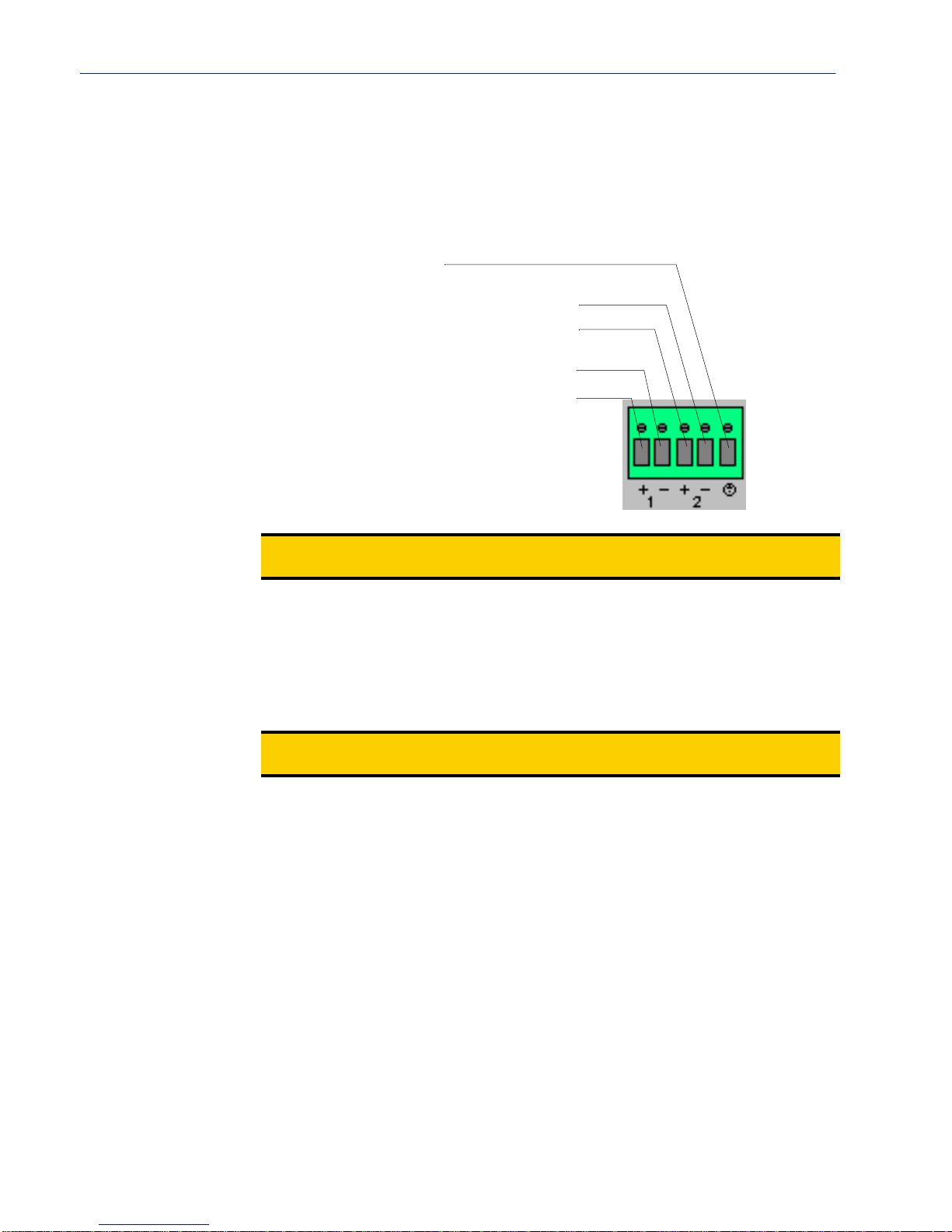
IOLAN Device Server Components
3. Connect the primary and secondary DC input using the following specifications:
a. Use wire gauge 20 to 22 AW G.
b. Strip insulation 7mm from wire ends. (If using stranded wire, twist all strands together to
ensure all wire strands are used for the connection.)
c. Connect supply with reference to the terminal bl ock diagram and electrical specifications:
Earthing wire
Secondary Supply: Negative (-) wire
Secondary Supply: Positive (+) wire
Primary Supply: Negative (-) wire
Primary Supply: Positive (+) wire
DC Power Supply
Note:
When connecting only a single power supply source, ensure the connection is the
primary supply and the secondary terminals are left unconnected.
Primary Supply:
Positive (+) wire to Circuit 1, terminal marked +
Negative (-) wire to Circuit 1, terminal marked -
Secondary (back-up) Supply:
Positive (+) wire to Circuit 2, terminal marked +
Negative (-) wire to Circuit 2, terminal marked -
Note:
When connecting dual power supply sources, the Device Server supports a common
positive (+) circuit arrangement ONLY.
Earthing Wire:
Ground wire to terminal marked with circular earthing symbol.
Screws:
Tighten terminal connector block screws to 7 lbs-inches torque.
4. Switch On the power supplies.
5. Switch On the Device Server. (The power LEDS 1 and 2 will indicate the status of the power
source at the respective input. If both the primary and secondary power source are available, both
LED 1 and LED 2 will be luminated indicated power detected from each input.)
Disconnecting 48V Power Supplies from the Device Server
To disconnect the power supply(s) from the Device Server, do the following:
1. Switch off the Device Server.
2. Switch off the power source(s).
3. Disconnect all DC power input cables from the Device Server terminal connector block.
4. Remove any attached devices to the serial or Ethernet port(s).
Your Device Server is ready to be moved.
Installation 35
Page 36
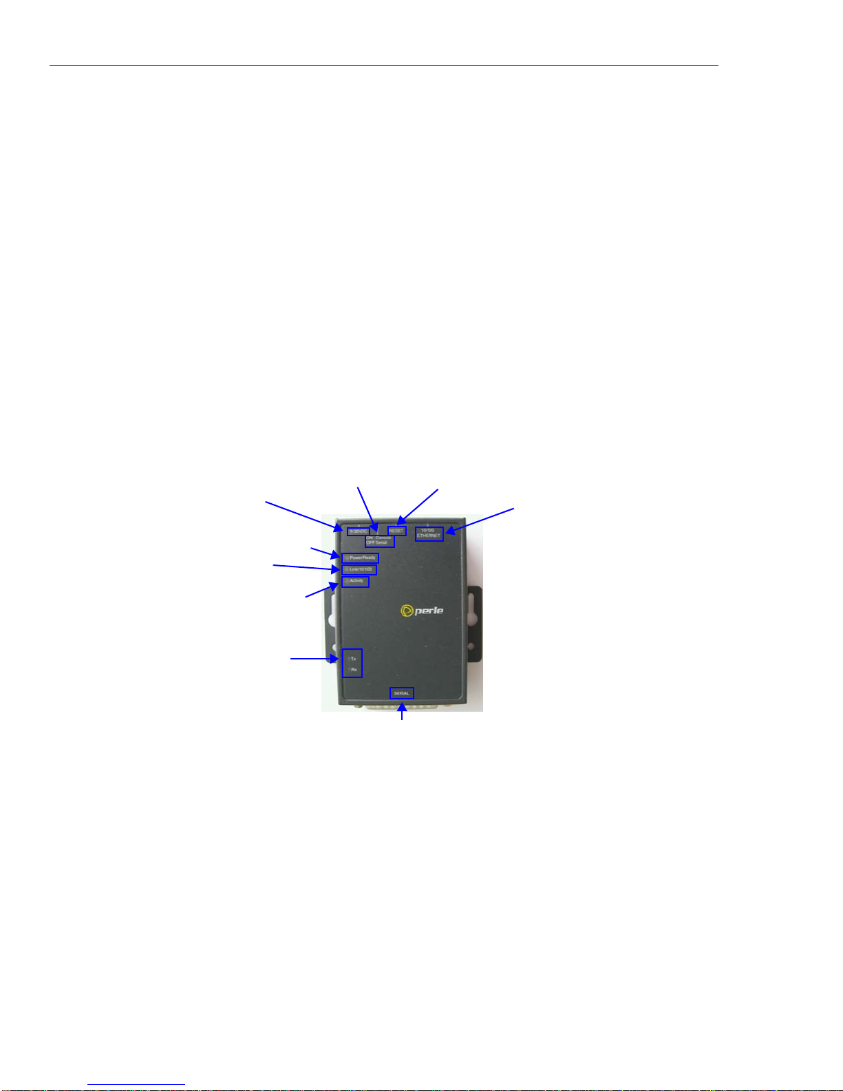
Getting to Know Your Device Server
Power Over Ethernet Specifications
The IOLAN Device Server SDS P models can only accept power from an IEEE 802.3AF compliant
PSE device. Power Source Equipment (PSE) can provide up to 13W of power to a powered device, in
this case, the Device Server, using one of the following methods:
z Using the two unused twisted pair wires (10/100Mb only).
z Using the two data pairs or "phantom power" method (100Mb).
The 1-port/4-port SDS P model comes with an external power supply, while the 2-port SDS P model
does not come with an external power supply option. If you are using the power over Ethernet feature
in conjunction with the serial power pinout, the power output is always 5 volts, regardless of ho w the
jumpers are set.
Getting to Know Your Device Server
The inset RESET button will reboot the Device Server if pushed in and released quickly and will
reset the Device Server to factory defaults if pushed in and held for more than three seconds.
1-Port
This section describes the components found on the Device Server 1-port models.
Console/Serial
Mode Switch
Power Supply
Power
LAN Connection
LAN Activity
Serial Activity
Serial Connection
The 1-port Device Server has one serial connection that is one of the following: DB25 male, DB25
female, RJ45, or DB9 male.
Reboot/Reset to
Factory Defaults
Ethernet
Interface
36 IOLAN Device Server User’s Guide, Version 2.5
Page 37
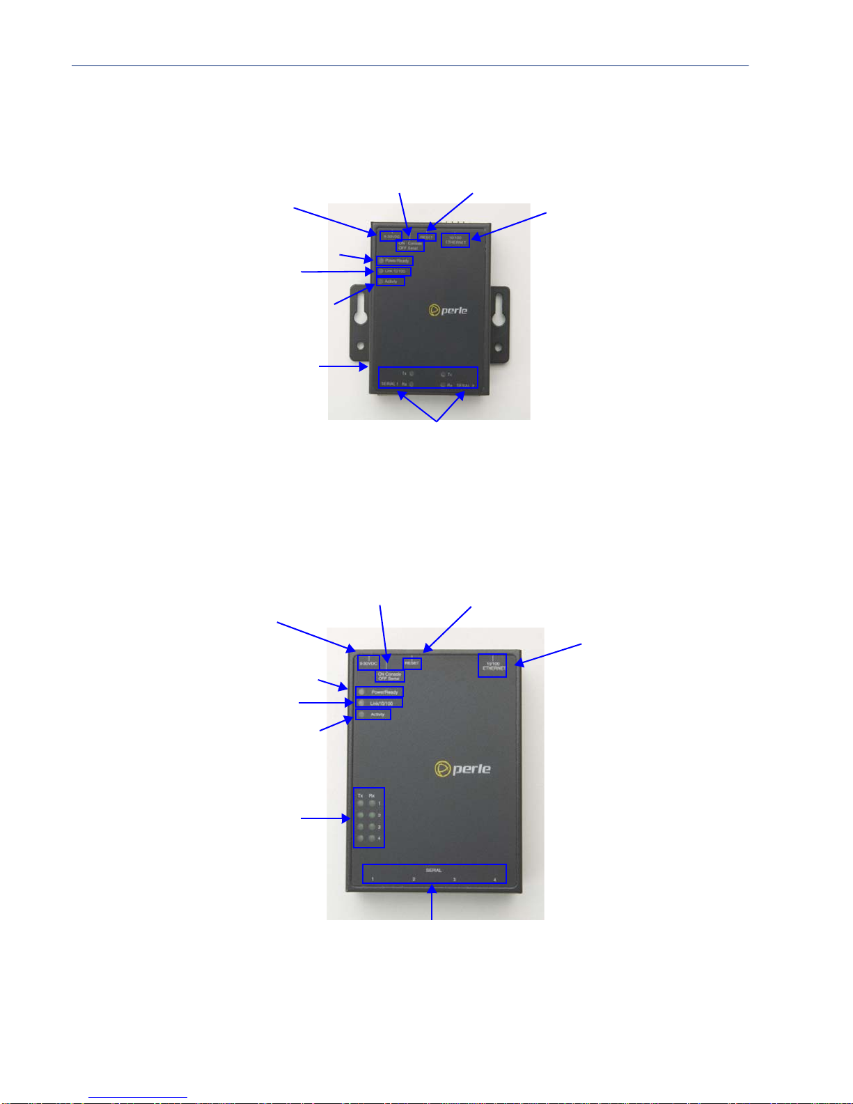
2-Port
Getting to Know Your Devi ce Server
This section describes the components found on the Device Server 2-port models.
Console/Serial
Mode Switch
Power Supply
Reboot/Reset to
Factory Defaults
Ethernet
Interface
Power
LAN Connection
LAN Activity
Serial Activity
Serial Connection
The 2-port Device Server has two RJ45 serial connections. If you are using the 2-port Device Server,
you can use an 8-pin connector if you do not need the power in (pin 1) or power out (pin 10) pins.
The 2-Port P model (power over Ethernet) does not come with a power supply.
4-Port
This section describes the components found on the Device Server 4-port models.
Console/Serial
Mode Switch
Reboot/Reset to
Factory Defaults
Power Supply
Ethernet
Interface
Power
LAN Connection
LAN Activity
Serial Activity
Serial Connection
The 4-port Device Server model has four RJ45 serial connections.
Installation 37
Page 38
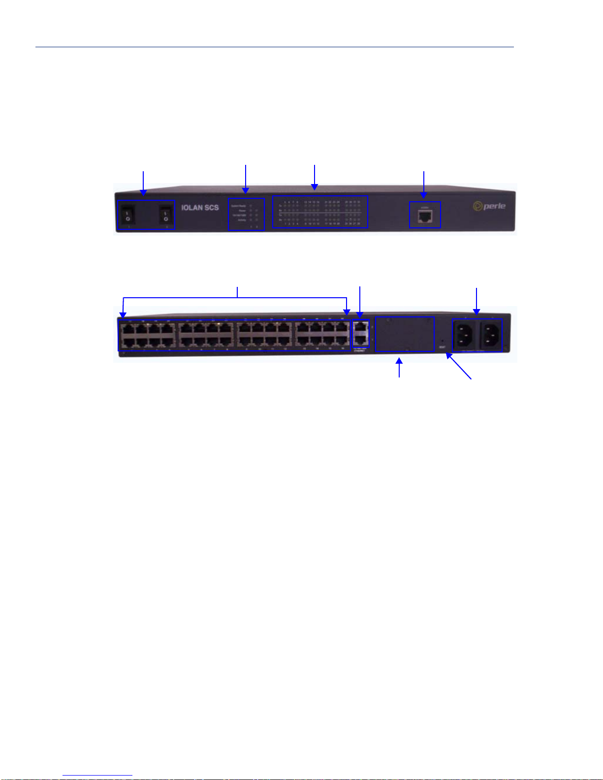
Getting to Know Your Device Server
Rack Mount
This section describes the basic components of all rack mount Device Server models. This example
uses an IOLAN SCS with dual ethernet and dual AC power.
Console Port/LED View
Power ON/OFF
Server LEDs
Serial/Ethernet View
Serial Ports
Installing a Rack Mount Device Server
Using the rack mount brackets included with your Device Server, you can rack mount the Device
Server from the front or the back of the chassis, depending on your environment. Make sure you
don’t block the Device Server’s side air vents. Each Device Server is 1U in height, and does not
require any extra space between units; therefore, you can rack mount up to five Device Servers in a
5U rack.
Line Serial Activity
Dual Ethernet
Console Port
PCI Card Faceplate
(SCS models only)
Dual AC Power
Reboot/Reset to
Factory Defaults
38 IOLAN Device Server User’s Guide, Version 2.5
Page 39

LED Guide
Getting to Know Your Devi ce Server
Desktop Models
The Device Server LEDs display the following information:
z Power/Ready—(Green/Red/Yellow) This LED starts out red at the beginning of power up. If
this LED remains red, indicates that there is a critical error (see
313). It flashes green to indicate that the Device Server is booting, then flashes green/yellow
when the firmware is being updated. This LED then remains solid green to indicate that the
Device Server is ready.
z Link/10/100
– Green—10 Mbits
– Yellow—100 Mbits
– Off—no LAN connection
z Activity—Flashes Green for transmit (TX) or receive (RX) LAN data
z Tx—Flashes with transmit serial activity
z Rx—Flashes with receive serial activity
z Downloading firmware—(Green/Yellow) The Device Server will flash green/yellow, indicating
that it is downloading new firmware.
Hardware Problems on page
Rack Mount Models
The Device Server LEDs display the following information:
z Power/Ready—(Green/Red/Yellow) When the Device Server boots up, it can experience one of
four possibilities:
–Good Boot: When the Device Server cycles through a good boot, the Power/Ready LED
cycles for several seconds and then stays a solid green.
– Noncritical Error Boot: When the Device Server cycles through a boot and a noncritical
error occurs, such as a bad port, the Power/Ready LED will flash red briefly before
displaying a solid green. You should reboot the Device Server while moni toring the Console
port to view the error information.
– Critical Error Boot: When the Device Server cycles through a boot and a critical error
occurs, such as corrupted firmware, the Power/Ready LED continues to flash red. View the
Device Server reboot through the Console port for information on how to correct the
problem.
– Fatal Error Boot: When the Device Server cycles through a boot and a fatal error occurs,
the Power/Ready LED stays a solid red (see
z Link/10/100/1000
– Green—10/100 Mbits
– Yellow—1000 Mbits
– Off—no LAN connection
z Activity—Flashes Green for transmit (TX) or receive (RX) LAN data
z Tx—Flashes with transmit serial activity
z Rx—Flashes with receive serial activity
z Downloading firmware—(Green/Yellow) The Device Server will flash green/yellow, indicating
that it is downloading new firmware.
Hardware Problems on page 313).
Installation 39
Page 40
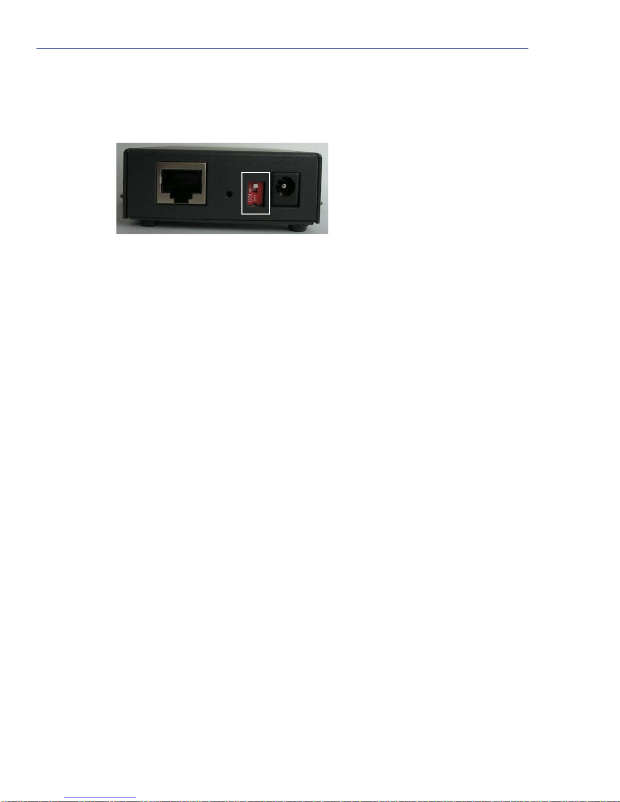
Powering Up the Device Server
Console Mode vs. Serial Mode: Desktop Models
You will notice a little switch at the back of the desktop Device Server models for switching the
Device Server to either Console or Serial mode. Note that the Extended Temperature models have
two switches, Switch 1 is used for Console mode and Switch 2 is unused.
When the switch is down (ON), the Device Server is in Console mode; when the switch is up, the
Device Server is in Serial mode. Console mode is used when you have a direct connection between a
serial device (like a terminal or a PC) and the Device Server, accessed by the Admin user to
configure/manage the Device Server. You can connect directly to the Device Server in Serial mode,
but the Device Server will not display all the messages/information you will get in Console mode.
Console mode automatically sets the
No, Bits to 8, Stop Bits to 1, and Parity to None, in addition to displaying extra system messages.
Your Device Server
Device Server ignores any
Serial mode is used when the Device Server acts as a communications server, or anytime you are not
connecting directly to the Device Server to configure it. On the 2-port/4-port desktop Device Server
model, the Console port is Port 1.
Line 1 will not work in a production environment in Console mode, because the
Line settings when in Console mode.
Serial Interface to EIA-232, Speed to 9600, Flow Control to
Dedicated Console Port: Rack Mount Models
The rack mount Device Server models have a dedicated Console port, located on the side of the
Device Server that displays the LEDs. You can configure the baud rate and flow control of the
dedicated Console port. You can view diagnostic information wh en you are con nected to the Console
port.
Powering Up the Device Server
Serial Only Models
Before you attach the Device Server to your network or try to configure it, we suggest that you power
it up to verify that it works properly. To power up the Device Server, perform the following steps:
1. Plug the external power supply into the Device Server and then into the electrical outlet or
connect it to the PSE if you have a P series (power over Ethernet) model.
2. If the Device Server is working correctly, you should see the LEDs cycle for several seconds and
then remain a solid green, indicating that it is ready to configure/use.
You are now ready to begin communicating wi th you r IOLAN Device Server. The last step of the
installation process is to set an IP address for the Device Server; this is necessary before it can be
configured and put into production.
Before you start to configure the Device Server, you should set the desktop Device Server jumpers if
you want to terminate the line or use the power in pin feature (instead of an external power supply, if
your desktop Device Server model supports it).
40 IOLAN Device Server User’s Guide, Version 2.5
Page 41

I/O Models
Setting Jumpers
Before you attach the Device Server to your network or try to configure it, we suggest that you power
it up to verify that it works properly. To power up the Device Server, perform the following steps:
1. Unplug the power plugable terminal block from the Device Server.
2. Loosen the screws and then insert your positive (+) wire into the left terminal and screw it down.
Insert the negative (-) wire into the right terminal and screw it down.
3. Plug the power terminal block back into the Device Server.
4. Plug the power supply into the electrical outlet.
5. If the Device Server is working correctly, you should see the LEDs cycle for several seconds and
then remain a solid green, indicating that it is ready to configure/use.
You are now ready to connect your I/O peripherals to the Devi ce Server and then begin
communicating with your IOLAN Device Server. The last step of the installation process is to set an
IP address for the Device Server; this is necessary before it can be configured and put into
production.
Before you start to configure the Device Server, you should set the Device Server jumpers for Digital
I/O (see
channels.
Digital I/O Module on page 46) or Analog Input (Analog Input Module on page 47)
Setting Jumpers
The Device Server contains jumpers that you might need to set before you configure it and put it into
production. You can set the power out pin, pin 9, to a fixed 5V DC output or to the external adapter
output; this can range from 9-30V DC (if an external adapter is shipped with the Device Server, it has
a 12V DC output). By default, the power out pin is set to no power. You can set the Device Server
line termination to
I/O models).
1-Port Device Server DB25 Male/Female
To change the settings, do the following:
1. Unplug the Device Server from the electrical outlet and disconnect everything from the box.
2. Open the case by unscrewing the two side screws, one on each side, and lifting off the top of the
case. You should see the followin g:
Pin1
Serial Connection
J9
J4
on or off (this is off by default) if you are using EIA-422/485 (not applicable for
Screw
DIP
J1
Switch
Power
Reset
RJ45
3. T o change the power pin out, locate J4. For the fixed 5V DC output, jumper pins 1 and 2. For the
output to equal the external adapter input, jumper pins 2 and 3.
4. To turn line termination on, locate and jumper both J1 and J9.
5. Close the Device Server case by replacing the case lid and the two screws. You can now power it
on with the new settings.
Screw
Installation 41
Page 42
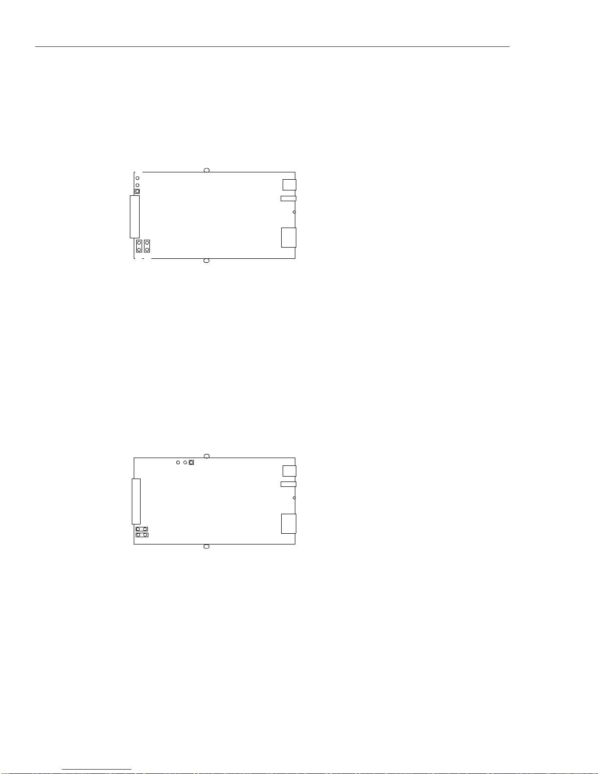
Setting Jumpers
1-Port Device Server RJ45
To change the settings, do the following:
1. Unplug the Device Server from the electrical outlet and disconnect everything from the box.
2. Open the case by unscrewing the two side screws, one on each side, and lifting off the top of the
case. You should see the followin g:
Screw
Screw
DIP
Switch
Power
Reset
RJ45
RJ45 Serial
J4
Pin1
J1
J9
3. T o change the power pin out, locate J4. For the fixed 5V DC output, jumper pins 1 and 2. For the
output to equal the external adapter input, jumper pins 2 and 3.
4. To turn line termination on, locate and jumper both J1 and J9.
5. Close the Device Server case by replacing the case lid and the two screws. You can now power it
on with the new settings.
1-Port Device Server RJ45 P (Power Over Ethernet)
To change the settings, do the following:
1. Unplug the Device Server from the electrical outlet and disconnect everything from the box.
2. Open the case by unscrewing the two side screws, one on each side, and lifting off the top of the
case. You should see the followin g:
Screw
J4
RJ45 Serial
J8
J7
Pin1
DIP
Switch
Screw
Power
Reset
RJ45
3. T o change the power pin out, locate J4. For the fixed 5V DC output, jumper pins 1 and 2. For the
output to equal the external adapter input, jumper pins 2 and 3.
4. To turn line termination on, locate and jumper both J7 and J8.
5. Close the Device Server case by replacing the case lid and the two screws. You can now power it
on with the new settings.
42 IOLAN Device Server User’s Guide, Version 2.5
Page 43
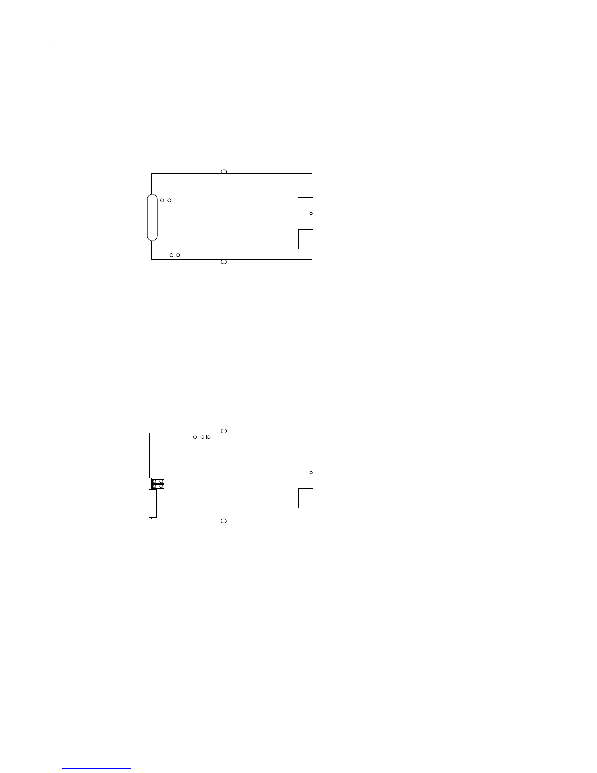
1-Port Device Server DB9
To change the settings, do the following:
1. Unplug the Device Server from the electrical outlet and disconnect everything from the box.
2. Open the case by unscrewing the two side screws, one on each side, and lifting off the top of the
case. You should see the followin g:
DB9 Serial
J9
Screw
DIP
Switch
Setting Jumpers
Power
Reset
J11
Screw
3. To turn line termination on, locate and jumper both J11 and J9.
4. Close the Device Server case by replacing the case lid and the two screws. You can now power it
on with the new settings.
2-Port Device Server SDS1M (Modem)
To change the settings, do the following:
1. Unplug the Device Server from the electrical outlet and disconnect everything from the box.
2. Open the case by unscrewing the two side screws, one on each side, and lifting off the top of the
case. You should see the followin g:
Screw
RJ45 Serial
J8
J7
Modem
J4
Pin1
DIP
Switch
RJ45
Power
Reset
RJ45
3. T o change the power pin out, locate J4. For the fixed 5V DC output, jumper pins 1 and 2. For the
output to equal the external adapter input, jumper pins 2 and 3.
4. To turn line termination on, locate and jumper both J7 and J8.
5. Close the Device Server case by replacing the case lid and the two screws. You can now power it
on with the new settings.
Screw
Installation 43
Page 44
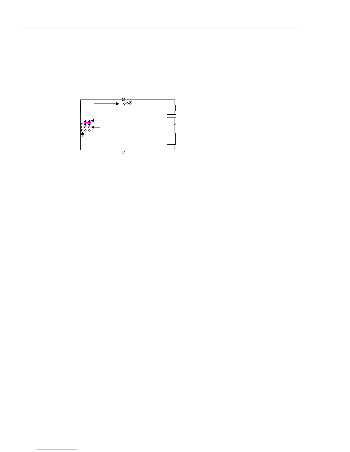
Setting Jumpers
2-Port Device Server
To change the settings, do the following:
1. Unplug the Device Server from the electrical outlet and disconnect everything from the box.
2. Open the case by unscrewing the two side screws, one on each side, and lifting off the top of the
case. You should see the followin g:
RJ45
1
J7
J9
Pin1
RJ45
2
3. To change the power pin out, locate the set of three pins associated with the line you want to set
(Line 1 is J4; Line 2 is the set the three pins just to the left of port 2). For the fixed 5V DC
output, jumper pins 1 and 2. For the output to equal the external adapter input, jumper pins 2
and 3.
4. To turn line termination on for Line 1, locate and jumper both J7 and J8 (as shown in the
diagram). To turn line termination
5. Close the Device Server case by replacing the case lid and the two screws. You can now power it
on with the new settings.
Screw
J4
Pin1
J8
J11
DIP
Switch
Power
Reset
RJ45
Screw
on for Line 2, locate and jumper both J11 and J9.
44 IOLAN Device Server User’s Guide, Version 2.5
Page 45
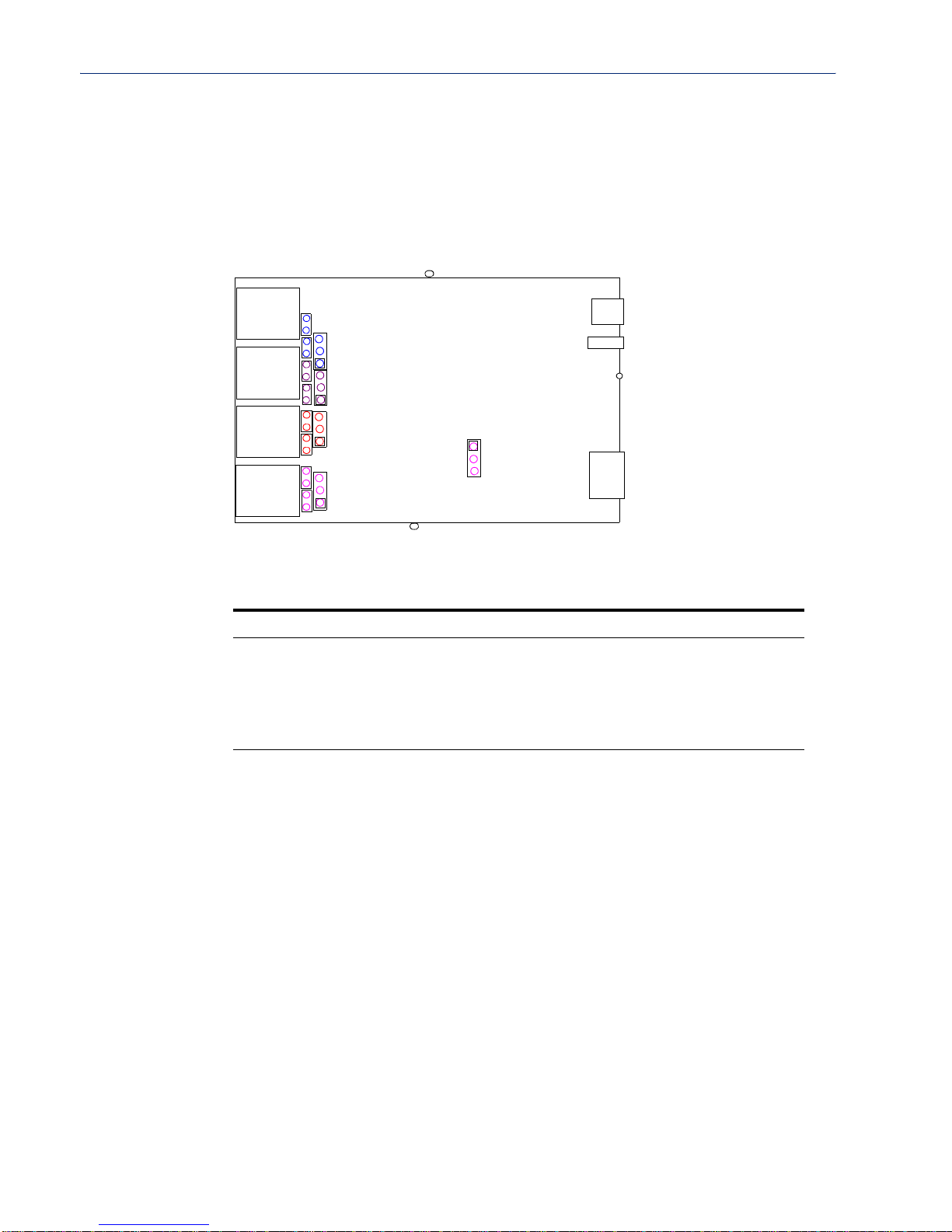
4-Port Desktop Device Server
To change the settings, do the following:
1. Unplug the Device Server from the electrical outlet and disconnect everything from the box.
2. Open the case by unscrewing the two side screws, one on each side, and lifting off the top of the
case. You should see the followin g:
Setting Jumpers
Screw
1
J8
J4
J7
J11
2
J5
J9
J24
3
J10
J22
The pin with the
square represents
DIP
Switch
Power
Reset
Pin 1 --->
J25
4
J6
J23
RJ45
Screw
3. The following table describes how to jumper the pins for line termination, fixed 5V output, and
for output equal to the external adapter input:
Port/Line # Line Termination 5V Output Input Volt Output
1 Jumper J7 and J8 J4, jumper pins 1 & 2 J4, jumper pins 2 & 3
2 Jumper J9 and J11 J5, jumper pins 1 & 2 J5, jumper pins 2 & 3
3 Jumper J22 and J24 J10, jumper pins 1 & 2 J10, jumper pins 2 & 3
4 Jumper J23 and J25 J6, jumper pins 1 & 2 J6, jumper pins 2 & 3
4. Close the Device Server case by replacing the case lid and the two screws. You can now power it
on with the new settings.
Installation 45
Page 46

Setting Jumpers
Digital I/O Module
Device Servers that have Digital I/O have an input/output jumper that mu st be set for each channel
and must match the software configuration for each channel. Depending on the model, the placement
of the digital I/O board can change, so the diagram below shows how to set jumper for any digital
board.To change the settings, do the following:
1. Detach the Device Server from the electrical power source and disconnect everything from the
box.
2. Open the case by unscrewing the five side screws, two on each side plus the grounding screw,
and lifting off the top of the case. You should see the following configurat ion for the digital I/O
board:
Channel 2/4
J5
Pin1
Pin1
J3
Channel 1/3
I/O
Note:
Jumper pins 1 and 2 for Input. Jumper pins 2 and 3 for Output.
3. To configure either Channel 1 or Channel 3 (depending on how many Digital channels your I/O
supports and following the mylar channel definitions) for Input, jumper J3 pin 1 and 2 (as
shown); this is the default setting. To configure either Channel 2 or Channel 4 (depending on
how many Digital channels your I/O supports and following the mylar channel definitions) for
Output, jumper J5 pin 2 and 3 (as shown).
4. Close the Device Server case by replacing the case lid and the five screws. You can now power it
on with the new settings.
46 IOLAN Device Server User’s Guide, Version 2.5
Page 47

Analog Input Module
Device Servers that have Analog Input have a voltage/current jumper that must be set for each
channel and must match the software configuration for each channel. To change the settings, do the
following:
1. Detach the Device Server from the electrical power source and disconnect everything from the
box.
2. Open the case by unscrewing the five side screws, two on each side plus the grounding screw,
and lifting off the top of the case. You should see the following configurat ion for the analog
input board:
Wiring I/O Diagrams
Channel 1
JP1 JP2
Channel 2
I/O
3. To configure Channel 1 for Voltage, no jumper should be set (as shown); this is the default
setting. To configure Channel 2 for Current, jumper both J2 pins (as shown).
4. Close the Device Server case by replacing the case lid and the five screws. You can now power it
on with the new settings.
Wiring I/O Diagrams
This section describes how to wire the various Device Server I/O models.
Digital I/O
Make sure the Digital I/O jumpers support the software setting; see Digital I/O Module on page 46
for jumper settings.
Digital Input Wet Contact
If you are using a wet contact for your Digital input, for channel D1 connect one wire to D1 and the
other wire to GND. The power source is supplied by the GND (ground) connector.
D1
Channel 3
JP3
D2
GND
I/O
COM
Channel 4
JP4
VCC
Power
Source
Installation 47
Page 48
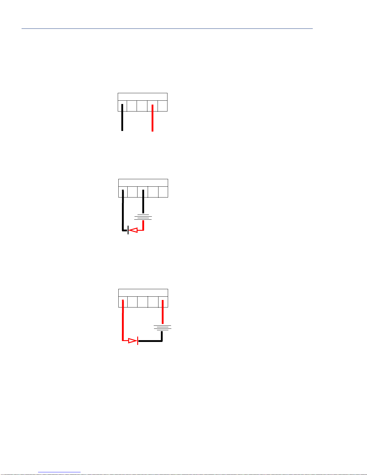
Wiring I/O Diagrams
Digital Input Dry Contact
If you are using a dry contact for your Digital input, for channel D1 connect one wire to D1 and the
other wire to COM. The power source is supplied by the COM (common) connector.
D1
D2
GND
COM
VCC
Power
Source
Digital Output Sink
For a Digital output sink (ground) configuration for channel D1, follow the diagram below.
D1
D2
GND
COM
VCC
Battery
+
-
+
Device
Digital Output Source
For a Digital output source (voltage) configuration for channel D1, follow the diagram belo w.
D1
D2
GND
COM
VCC
+
Battery
+
Device
-
-
48 IOLAN Device Server User’s Guide, Version 2.5
Page 49

Analog Input
Wiring I/O Diagrams
Make sure the Analog jumpers support the software setting; see Analog Input Module on page 47 for
jumper settings.
Current
To connect channel A1 with a 2-wire shielded cable, connect the positive wire to A1+, the negative
wire to A1-, and optionally the shield to GND.
A1+
A1-
A2+
A2-
-
+
If you have the positive/negative wires reversed, the output will always read 0 (zero).
A3+
A3-
A4+
A4-
GND
shield
Voltage
To connect to Channel A1 with a 2-wire shielded cable, connect the positive wire to A1+, the
negative wire to A1-, and optionally the shield to GND.
If you have the positive/negative wires reversed, the polarity of the voltage will be reversed.
Temperature Input
If you are using RTD sensors, a short detected status will be displayed if the wires are connected
improperly. RTD or thermocouple sensors will display an open detection status when the circuit is
broken.
Thermocouple
To connect to Channel A1 with a 2-wire cable, connect the positive wire to A1+ and the negative
wire to A1-; you will not be using the A1s connection.
A1+
A1-
A2+
A2-
-
+
A1+
A1-
A1s
A2+
A2-
A3+
A3-
A4+
A4-
GND
shield
A3+
A3-
A3s
A2s
A4+
A4-
A4s
-
+
Installation 49
Page 50
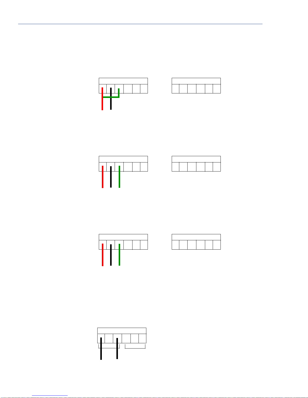
Wiring I/O Diagrams
RTD 2-Wire
In a 2-wire RTD configuration, connect the excite wire to A1-, the return wire to A1+, an d ju mper the
sense wire from A1s with a insulated wire going to A1+.
A3+
A3-
A3s
A1+
A1-
A1s
sense
A2+
A2s
A2-
A4+
A4s
A4-
return
excite
RTD 3-Wire
In a 3-wire RTD configuration, connect the return wire to A1+, the excite wire to A1-, and the sense
wire to A1s.
A3+
A3-
A1+
return
excite
A3s
A1-
A1s
A2+
sense
A2s
A2-
A4+
A4-
A4s
RTD 4-Wire
In a 4-wire RTD configuration, connect the return wire to A1+, the excite wire to A1-, the sense wire
to A1s, and leave the fourth wire disconnected.
A3+
A3-
A3s
A1+
A1-
A1s
A2+
A2s
A2-
A4+
A4-
A4s
return
Relay Output
Normally Open Contact
To connect Relay channel R1 for a circuit that is normally inactive, connect one wire to the COM
(common) connector and one wire to the NO (normally open) connector.
COMNCNONOCOM
50 IOLAN Device Server User’s Guide, Version 2.5
excite
R1
sense
NC
R2
Page 51

Setting an Initial IP Address
Normally Closed Contact
To connect relay channel R1 for a circuit that is normally active, connect one wire to the COM
(common) connector and one wire to the NC (normally closed) connector.
COMNCNONOCOM
R1
NC
R2
Setting an Initial IP Address
This section describes the different methods you can use to set the Device Server IP address.
Following is a list of methods for setting the Device Server IP address and a short explanation of
when you would want to use that method:
z Easy Config Wizard—The Easy Config Wizard is automatically launched from the CD ROM
included with your Device Server. Y o u can use the Easy Config Wizard to set the Device
Server’s IP address and configure the line(s).
z DeviceManager—Use this method when you can connect the Device Server to the network and
access the Device Server from a Windows
application that can be used for Device Server configuration and management.
z Direct Connection—Use this method when you can connect the Device Server directly to a
dumb terminal, essentially logging directly into the Device Server. Using this method, you will
need to configure and/or manage the Device Server using either the Menu or CLI.
z DHCP/BOOTP—Use this method when you have a BOOTP or DHCP server running and you
can connect the Device Server to your network. The Device Server will automatically obtain an
IP address from a local network DHCP/BOOTP server when this service is enabled (it is
disabled by default).
z ARP-Ping—Use this method when you can connect the Device Server to the network and want
to assign a temporary IP address to the Device Server by specifying an ARP entry and then
pinging it.
z IPv6 Network—When the Device Server is connected to an IPv6 network, its local link address
is determined using stateless auto configuration.
®
PC. The DeviceManager is a Windows-based
Note:
Regardless of which method you use, the Device Server must reside within the same network
as the host you are accessing it from.
Once an IP address has been assigned to the Device Server, in most cases, you can continue to use the
same method to configure and/or manage the Device Server. See
on page 65 for more information on the different methods you can use to manage/configure the
Device Server.
Chapter 3, Configuration Methods
Installation 51
Page 52

Setting an Initial IP Address
Using DeviceManager
To use the DeviceManager, you must first install it on a Windows 98/2000/NT/ME/Server 2003/XP
operating system (Windows NT requires Service Pack 4 or later) that resides in the same network as
the Device Server. The DeviceManager installation wizard can be found on the CD-ROM included in
the Device Server package.
1. Connect the Device Server to the LAN and plug it in; it will automatically boot up (rack mount
models will need to be turned On).
2. From the CD-ROM that was included in the Device Server packaging, select the DeviceManager
link.
3. Click on the link under Location and click Open to automatically start the DeviceManager
installation.
4. Install the DeviceManager by following the installation wizard. On the last window, check the
Yes, I want to launch DeviceManager now. box and click the Finish button.
5. On the Manage Device Server tab, click the Search Local Network button.
6. Any Device Server that does not have an IP address will be displayed as Not Configured, with
the
Model and MAC Address to identify the Device Server. Highlight the Device Server that you
want to assign an IP address to and click the
7. Type in the IP address that you want to assign to this Device Server and click the Assign IP
button.
Assign IP button.
Note:
This is just a temporary IP address that you can use to open a session to the Device
Server for configuration.
8. You are now ready to configure the Device Server. Double-click the Device Server you just
assigned the temporary IP address to, to open a configuration session. Type
factory default Admin user password) in the Login window and click
superuser (the
OK.
9. Expand the Server Configuration folder and select Server. You can choose to enter a permanent
IP address in the
Note:
If your network runs a DHCP server and you don’t want the Device Server to obtain its
IP Address from the DHCP server (or if you’re not sure if there is a DHCP server and
you want to assign a permanent
Internet Address field and the Subnet/Prefix Bits field of the Server window.
IP Address), disable the DHCP/BOOTP Service in this
window.
10. Click the Apply button when you’re done with the Server window. To permanently assign the IP
address, you need to download the new configuration file and then reboot the Device Server.
11. Download the configuration file to the Device Server by selecting Tools, Download
Configuration to Unit
.
12. Reboot the Device Server by selecting Tools, Reboot Server.
For more information on configuring the Device Server using DeviceManager, see Chapter 5, Using
the DeviceManager on page 115.
52 IOLAN Device Server User’s Guide, Version 2.5
Page 53

Using a Direct Connection
You can connect to the Device Server using a PC with a terminal emulation package, such as
HyperTerminal or a terminal.
1. Connect the Device Server to your PC or dumb terminal. Make sure the DIP switch is in Console
mode (desktop models, this sets the Device Server serial port to EIA-232) or that you are
connected to the dedicated Console port (rack mount models). When connecting a terminal or PC
directly (without modems), the EIA-232 signals need to be crossed over (‘null modem’ cable).
See
EIA-232 Cabling Diagrams on page 61 for cabling diagrams.
2. Using a PC emulation application, such as HyperTerminal, or from a dumb terminal, set the Port
settings to 9600 Baud, 8 Data bits, No Parity, 1 Stop Bits, and No Hardware Flow control to
connect to the Device Server. You can change these settings for future connections on the rack
mount models (the Device Server must be rebooted for these changes to take place).
3. When prompted, type admin for the User and superuser for the Password. Y ou should now see
the a prompt that displays the model type and port number; for example,
4. You are now logged into the Device Server and can set the IP address by typing from the
command line using the Command Line Interface (CLI).
For single Ethernet connection models, type:
set server internet <ipv4address>
Setting an Initial IP Address
SCS16#.
For dual Ethernet connection models, type:
set server internet eth1 <ipv4address>
Where ipv4address is the IP Address being assigned to the Device Server.
5. T ype the following command:
save
6. If you are going to use another configuration method, such as WebManager or DeviceManager,
unplug a desktop Device Server or turn Off a rack mount Device Server. On a desktop Device
Server, change the DIP switch to Off Serial (DIP switch in the up position) and connect it to your
serial device. Plug the Device Server back in, automatically rebooting the Device Server in the
process.
7. If you want to complete the configuration using a direct connection, see Chapter 3,
Configuration Methods on page 65 and/or Chapter 6, Command Line Interface on page 201.
After you complete configuring the Device Server, unplug the Device Server. Change the Device
Server DIP switch to Off Serial (DIP switch in the up position) and connect it to your serial
device. Plug the Device Server back in, automatically rebooting the Device Server in the process.
Installation 53
Page 54

Setting an Initial IP Address
Using DHCP/BOOTP
If you are using BOOTP, you need to add an entry for the Device Server that associates the MAC
address (found on the back of the Device Server) and the IP address that you want to assign to the
Device Server. After you have made the MAC address/IP address association for BOOTP, use the
following directions for BOOTP or DHCP.
You can connect to the Device Server using a PC with a terminal emulation package, such as
HyperTerminal or a terminal.
1. Connect the Device Server to your PC or dumb terminal. Make sure the DIP switch is in Console
mode (desktop models, this sets the Device Server serial port to EIA-232) or that you are
connected to the dedicated Console port (rack mount models). When connecting a terminal or PC
directly (without modems), the EIA-232 signals need to be crossed over (‘null modem’ cable).
See
EIA-232 Cabling Diagrams on page 61 for cabling diagrams.
2. Using a PC emulation application, such as HyperTerminal, or from a dumb terminal, set the Port
settings to 9600 Baud, 8 Data bits, No Parity, 1 Stop Bits, and No Hardware Flow control to
connect to the Device Server. You can change these settings for future connections on the rack
mount models (the Device Server must be rebooted for these changes to take place).
3. When prompted, type admin for the User and superuser for the Password. Y ou should now see
the a prompt that displays the model type and port number; for example,
4. You are now logged into the Device Server and can set the IP address by typing from the
command line using the Command Line Interface (CLI). Type the following command:
set server service dhcp/bootp o n
5. T ype the following command:
save
6. The the following command:
reboot
7. When the Device Server reboots, it will automatically poll for an IP address from the
DHCP/BOOTP server. If you have a Device Server with dual Ethernet, each Ethernet connection
will automatically be assigned an IP address, you can access the Device Server through either IP
address.
If for some reason it cannot obtain an IP address from your DHCP/BOOTP server, you will have to
either connect to the Device Server on the console port and reboot it or push the Reset to Factory
button to access the Device Server.
You are now ready to configure the Device Server. See Chapter 3, Configuration Methods on page
65 for information on the different Device Server configuration methods.
SCS16#.
54 IOLAN Device Server User’s Guide, Version 2.5
Page 55

Using ARP-Ping
You can use the ARP-Ping (Address Resolution Protocol) method to temporarily assign an IP address
and connect to your Device Server to assign a permanent IP address. To use ARP-Ping to temporarily
assign an IP address:
1. From a local UNIX/Linux host, type the following at the system command shell prompt:
arp -s a.b.c.d aa:bb:cc:dd:ee:ff
On a Windows® 98 or newer system, type the following at the command prompt:
arp -s a.b.c.d aa-bb-cc-dd-ee-ff
(where a.b.c.d is the IPv4 address you want to temporarily assign to the Device Server, and
aa:bb:cc:dd:ee:ff is the Ethernet (MAC) address of Device Server, found on the back of the
unit.
2. Whether you use UNIX or Windows®, you are now ready to ping to the Device Server. Here is a
UNIX example of the sequence to use:
arp -s 192.168.209.8 00:80:d4:00:33:4e
ping 192.168.209.8
You are now ready to configure the Device Server. See Chapter 3, Configuration Methods on page
65 for information on the different Device Server configuration methods.
Setting an Initial IP Address
IPv6 Network
The Device Server has a factory default link local IPv6 address that takes the following format:
Device Server MAC Address: 00-80-D4-AB-CD-EF
Link Local Address: fe80::0280:D4ff:feAB:CDEF
The Device Server will also listen for IPv6 router advertisements to learn a global address. You do
not need to configure an IPv4 address for a Device Server residing in an IPv6 network.
You are now ready to configure the Device Server. See Chapter 3, Configuration Methods on page
65 for information on the different Device Server configuration methods.
Installation 55
Page 56
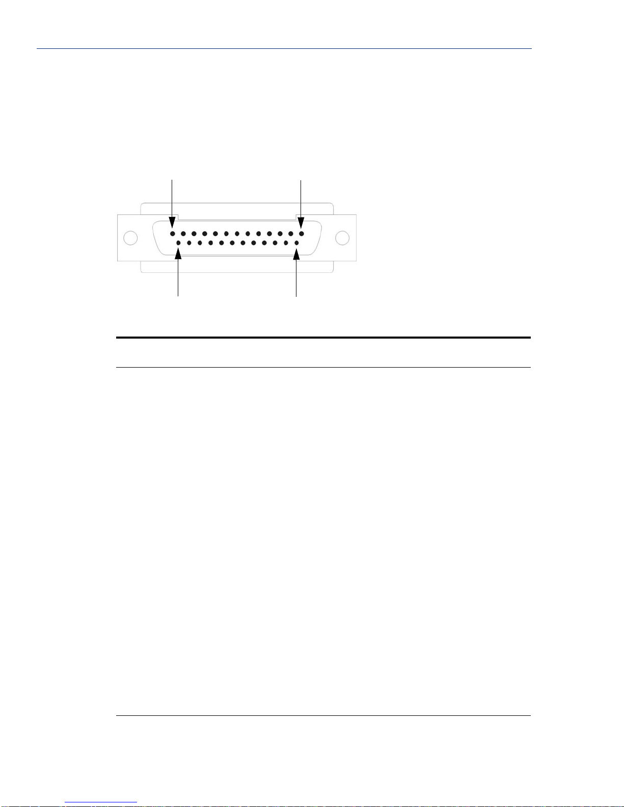
Serial Pinouts
Serial Pinouts
DB25 Male
This section defines the pinouts for the DB25 male connection used on the 1-port Device Server. The
power out pin, Pin 9, is available in the SDS model only.
Pin 1
Pin 14
The following table provides pinout information:
Pinout EIA-232
1 Shield Shield Shield Shield
2 (out) TxD
3 (in) RxD
4 (out) RTS
5 (in) CTS
6 (in) DSR
EIA-422
Pin 13
Pin 25
EIA-485
Full Duplex
EIA-485
Half Duplex
7 GND GND GND GND
8 (in) DCD
9 Power out Power out Power out Power out
12 Power in Power in Power in Power in
13 CTS14 TxD+ TxD+ DATA+
15 TxD- TxD- DATA18 RTS+
19 RTS20 (out) DTR
21 RxD+ RxD+
22 RxD- RxD25 CTS+
The power in pin, pin 12, can be 9-30V DC.
56 IOLAN Device Server User’s Guide, Version 2.5
Page 57

DB25 Female
This section defines the pinouts for the DB25 female connection used on the 1-port Device Server.
The power out pin, Pin 9, is available in the SDS model only.
Serial Pinouts
Pin 13
Pin 25
The following table provides pinout information:
Pinout EIA-232
1 Shield Shield Shield Shield
2 (in) RxD
3 (out) TxD
4 (out) CTS
5 (in) RTS
6 (in) DTR
EIA-422
Pin 1
Pin 14
EIA-485
Full Duplex
EIA-485
Half Duplex
7 GND GND GND GND
8 (in) DCD
9 Power out Power out Power out Power out
12 Power in Power in Power in Power in
13 RTS14 RxD+ RxD+ DATA+
15 RxD- RxD- DATA18 CTS+
19 CTS20 (out) DSR
21 TxD+ TxD+
22 TxD- TxD25 RTS+
The power in pin, pin 12, can be 9-30V DC.
Installation 57
Page 58

Serial Pinouts
RJ45
This section defines the pinouts for the RJ45 connection . 1-port, 2-port, and 4-port deskto p Device
Server models have a 10-pin RJ45 connector and all rack mount Device Server models have an 8-pin
RJ45 connector. These pinouts do not apply to I/O models.
Pin 1
Pin 10
The following table provides pinout information:
Pinout
10-pin
Pinout
8-pin EIA-232
EIA-422
EIA-485
Full Duplex
EIA-485
Half Duplex
1 Power In Power In Power In Power In
2 (in) 1 DCD
3 (out) 2 RTS TxD+ TxD+ DATA+
4 (in) 3 DSR
5 (out) 4 TxD TxD- TxD- DATA6 (in) 5 RxD RxD+ RxD+
7 6 GND GND GND GND
8 (in) 7 CTS RxD- RxD9 (out) 8 DTR
10 Power out Power out Power out Power out
The power in pin, Pin 1, can be 9-30V DC. The 2-port Device Server has power in on Port 2 only.
The 4-port Device Server has power in on Port 4 only.
58 IOLAN Device Server User’s Guide, Version 2.5
Page 59

DB9 Male (Serial Only)
This section defines the pinouts for the DB9 male connection used on the 1-port Device Server that is
serial only (not I/O).
Serial Pinouts
DB9 Male I/O
The following table provides pinout information:
Pinout
9-pin
EIA-232
EIA-422/485
Full Duplex
EIA-485
Half Duplex
1 (in) DCD
2 (in) RxD RxD+
3 (out) TxD TxD+ DATA+
4 (out) DTR
5 GND GND GND
6 (in) DSR RxD7 RTS
8 (in) CTS
9 TxD- DATA-
This section defines the pinouts for the DB9 male connection used on the 1-port Device Server I/O
models.
The following table provides pinout information:
Pinout
9-pin
EIA-232
1(in) DCD
2 (in) RxD RxD+
3 (out) TxD TxD- TxD-/RxD4 (out) DTR
5 GND GND GND
6 (in) DSR RxD7 RTS TxD+ TxD+/RxD+
8 (in) CTS
9
EIA-422/485
Full Duplex
EIA-485
Half Duplex
Installation 59
Page 60

Power Over Ethernet Pinouts
Power Over Ethernet Pinouts
This section defines the pinouts for the RJ45 Ethernet connection used on the Device Server SDS P
or Device Server SCS P models.
Pin 1
Pin 8
The following table provides pinout information:
Pinout Standard 802.3AF Unit-4 Wire 802.3AF Unit-8 Wire
1 Tx+ Tx+/+Voltage Tx+
2 Tx- Tx-/+Voltage Tx3 Rx+ Rx+/-Voltage Rx+
4 N/C +Voltage
5 N/C +Voltage
6 Rx- Rx-/-Voltage Rx7 N/C -Voltage
8 N/C -Voltage
60 IOLAN Device Server User’s Guide, Version 2.5
Page 61

EIA-232 Cabling Diagrams
This section shows how to create EIA-232 cables that are compatible with the Device Server.
Terminal DB25 Connector
The following diagrams show how the null modem cable should be configured when connecting to a
terminal DB25.
DB25 Male
EIA-232 Cabling Diagrams
IOLAN DS1
DB25 (DTE)
2 (TxD) 3 (RxD)
3 (RxD) 2 (TxD)
4 (RTS) 5 (CTS)
5 (CTS) 4 (RTS)
6 (DSR) 20 (D TR)
7 (GND) 7 (GND)
20 (DTR) 6 (DSR)
DB25 Female
IOLAN DS1
DB25 (DCE)
3 (TxD) 3 (RxD)
2 (RxD) 2 (TxD)
5 (RTS) 5 (CTS)
Terminal DB25
(DTE)
Terminal DB25
(DTE)
4 (CTS) 4 (RTS)
20 (DSR) 20 (DTR)
7 (GND) 7 (GND)
6 (DTR) 6 (DSR)
Installation 61
Page 62

EIA-232 Cabling Diagrams
RJ45
IOLAN RJ45
10-pin 8-pin
4 (DSR) 3 20 (DTR)
3 (RTS) 2 5 (CTS)
5 (TxD) 4 3 (RxD)
6 (RxD) 5 2 (TxD)
7 (GND) 6 7 (GND)
8 (CTS) 7 4 (RTS)
9 (DTR) 8 6 (DSR)
DB9 Male
Terminal DB25
(DTE)
IOLAN DS1
DB9 Male
3 (TxD) 3 (RxD)
2 (RxD) 2 (TxD)
7 (RTS) 5 (CTS)
8 (CTS) 4 (RTS)
6 (DSR) 20 (D TR)
5 (GND) 7 (GND)
4 (DTR) 6 (DSR)
Terminal DB25
(DTE)
62 IOLAN Device Server User’s Guide, Version 2.5
Page 63

Modem DB25 Connector
The following diagrams show how a standard straight through cable should be configured when
connecting to a DB25 modem.
DB25 Male
EIA-232 Cabling Diagrams
IOLAN DS1
DB25 (DTE)
2 (TxD) 2 (RxD)
3 (RxD) 3 (TxD)
4 (RTS) 4 (CTS)
5 (CTS) 5 (RTS)
6 (DSR) 6 (DSR)
7 (GND) 7 (GND)
8 (DCD) 8 (DCD)
20 (DTR) 20 (DTR)
RJ45
IOLAN RJ45
10-pin 8-pin
2 (DCD) 1 8 (DCD)
Modem DB25
(DCE)
Modem DB25
(DCE)
3 (RTS) 2 4 (CTS)
4 (DSR) 3 6 (DSR)
5 (TxD) 4 2 (Rx D)
6 (RxD) 5 3 (TxD)
7 (GND) 6 7 (GND)
8 (CTS) 7 5 (RTS)
9 (DTR) 8 20 (DTR)
Installation 63
Page 64

EIA-232 Cabling Diagrams
DB9 Male
IOLAN DS1
DB9 Male
1 (DCD) 8 (DCD)
2 (RxD) 3 (TxD)
3 (TxD) 2 (RxD)
4 (DTR) 20 (DTR )
5 (GND) 7 (GND)
6 (DSR) 6 (DSR)
7 (RTS) 4 (CTS)
8 (CTS) 5 (RTS)
Modem DB25
(DCE)
64 IOLAN Device Server User’s Guide, Version 2.5
Page 65

Configuration Methods Chapter 3
3
Introduction
This chapter provides information about the different methods you can use to configure the Device
Server. Before you can configure the Device Server, you must assign an IP address to the Device
Server. You can assign an IP address to the Device Server using one of the following methods:
z Using the DeviceManager as described in Using DeviceManager on page 52.
z Using ARP-Ping as described in Using ARP-Ping on page 55.
z Using a direct connection to the Admin port as described in Using a Direct Connection on page
53.
DeviceManager
The DeviceManager is a fully functional Windows 98/NT/2000/ME/Server 2003/XP Device Server
configuration/management tool. You must install the DeviceManager from the CD-ROM included
with the Device Server. Through the DeviceManager, you can:
z assign an IP address to new Device Servers.
z perform firmware updates.
z create configuration files, which can be immediately downloaded to the Device Server.
z save configuration files locally in the Device Server’s native binary format or to a text file. The
text configuration file can be edited with a text editor.
z open a session to a Device Server and import a (saved) configuration file.
z view statistics for a Device Server.
z download/upload keys/certificates to/from the Device Server.
z download custom files, such as new terminal definitions and a custom language file.
z download a configuration file to multiple Device Servers.
You can use the DeviceManager as a stand-alone application to create configuration files that can be
saved locally or you can use the DeviceManager to open a session to a Device Server to actively
manage and configure it.
See Chapter 5, Using the DeviceManager on page 115 for information on configuring/managing the
Device Server with DeviceManager.
IOLAN Device Server User’s Guide, Version 2.5 65
Page 66

WebManager
WebManager
The WebManager is a web-browser based method of configuring/ma nagi ng a Device Server.
To access a Device Server through the WebManager, open up your web browser and type in the IP
address of the Device Server that you want to manage/configure. A login screen will appear. Before
you type in the Admin user password (the factory default password is
Secure Login Click Here
Passphrase must already be defined in the Device Server configuration and the SSL/TLS
certificate/private key and CA list must have already been downloaded to the Device Server; see
and Certificates on page 94 for more information). If you are accessing the Device Server in
non-secure HTTP, just type in the Admin password.
Using the WebManager
The Server Configuration window is displayed after you first log on. The running Device Server
configuration is displayed in the WebManager. You navigate through the different configuration
windows by selecting the configuration window from the drop-down options in the upper-lefthand
corner of the browser.
When you have completed all the changes to a configuration window, click the Submit button. After
you make all your configuration changes, click the
to take effect immediately, click the
and then click the
Save to FLASH button, your changes will be lost the next time the Device Server reboots. After you
click the
Reboot button, you will need to reconnect and login to the Device Server.
superuser), select the For a
link if you are using the secure HTTP (HTTPS) mode (the SSL
Keys
Save to FLASH button. If you want your changes
Reboot button. Yo u can make changes to a line, Submit them,
Kill Line button to test the changes immediately; however, if you do not click the
CLI
Menu
Note:
The Command Line Interface (CLI) is a command line option for Device Server
configuration/management and user access. See
a full explanation of how to use the CLI.
If you are an existing IOLAN+ customer and would like to configure the Device Server in the native
IOLAN+ CLI, you can type the command
User Level Normal or higher). See your IOLAN User’s Guide for information on using the IOLAN+
CLI. See
Note:
The Menu is a window-oriented Device Server configuration and user access option. To manage the
Device Server, you will also need to use the CLI, WebManager, or DeviceManager, as you cannot
download or upload files to the Device Server through the Menu.
If you are an existing IOLAN+ customer and would like to configure the Device Server in the native
IOLAN+ menu interface, you can type the command
menu interface (you must have
on using the IOLAN+ interface. See
IOLAN+ interface.
Use the WebManager’s drop-down menus to navigate through the WebManager. Do not use
the browser’s Back button.
Chapter 6, Command Line Interface on page 201 for
iolan+ to use the native IOLAN+ CLI (you must have
IOLAN+ Interface on page 69 for more information about IOLAN+ interface.
The IOLAN+ interface not supported on Device Server models with more than 16 ports or
the DS1 model.
iolan+ to display and use the native IOLAN+
User Level Normal). See your IOLAN User’s Guide for information
IOLAN+ Interface on page 69 for more information about
66 IOLAN Device Server User’s Guide, Version 2.5
Page 67

Accessing the Menu
Menu access is available to any user whose Line Service is set to DSLogin, and whose User Service
is set to
z Menu—Users with User Level Menu will only see the sessions that have been set up for them.
DSPrompt. What the user sees depends on what the User Level is set to:
They can start predefined sessions, kill (stop) a running session, resume a session, and logout of
the Device Server.
z Restricted—Users with User Level Restricted can basically perform the same tasks as a Menu
user, except that they have the option of performing these tasks via the Menu or the CLI.
z Normal—Users with User Level Normal can do everything a Restricted user can do, plus start a
free session (connecting to any host on the network), set up their own user parameters (sessions,
password, language, hotkey prefix), define their terminal, and become the Admin user (if they
know the Admin password).
z Admin—Users with User Level Admi n (not the Admin user), have complete access to the
Device Server, the same as the Admin user. Through the Menu program, the Admin level user
can configure the Device Server, although there are several tasks that can only be done in the
CLI, such as downloading and uploading files and saving the configuration to FLASH.
Menu Conventions
You select an option from the Menu by using the keyboard up and down arrows to navigate the list.
When the menu item you want to access is highlighted, press the
list of options or to get the configuration screen, depending on what you select. When you are done
configuring parameters in a screen, press the
exit the form
you will be prompted with
to return to the screen so you can press
If there are a number of predefined options available for a field, you can scroll through those items by
pressing the
arrows to highlight the option you want, and then press
DHCP/BOOTP
Enter key to either get to the next
Enter key and then the Enter key again to Accept and
. If you want to discard your changes, press the Esc key to exit a screen, at which point
Changes will be lost, proceed? (y/n), type y to discard your changes or n
Enter to submit your changes.
Space Bar or you can type l (lowercase L) to get a list of options, use the up/down
Enter to select it.
DHCP/BOOTP
If you have a DHCP/BOOTP server and the Device Server’s Server Service DHCP/BOOTP is
enabled, the Device Server can obtain its IP address and several configuration parameters from the
DHCP/BOOTP server when it boots up. However, you must use another method for creating the
configuration file, like the DeviceManager, WebManager, or the CLI. See
Parameters on page 101 for more information on the DHCP/BOOTP parameters that can be set for
the Device Server.
When DHCP/BOOTP is enabled and there is a DHCP/BOOTP server within the network, the IP
Address obtained from DHCP/BOOTP will always override the Device Server’s configured IP
Address when the Device Server is rebooted.
DHCP/BOOTP
Configuration Methods 67
Page 68
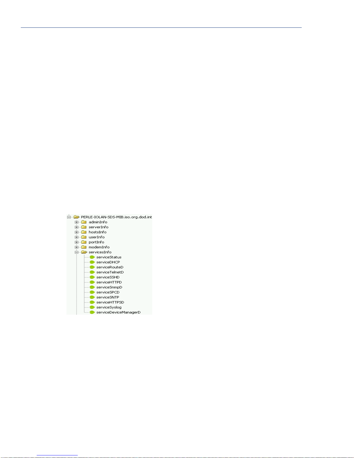
SNMP
SNMP
Before you can configure/manage the Device Server using SNMP, you need to set the Device Server
IP address and configure a read-write user for SNMP version 3 or a community for SNMP version 1
or 2. You can use DeviceManager, CLI, or the Menu to set the IP address and user/community (don’t
forget to reboot the Device Server before connecting with the SNMP manager to make your changes
take effect).
Required Support MIBs
You need to have the following MIBs installed in your SNMP manager:
z SNMPv2-SMI
z SNMPv2-TC
z IPV6-TC
Configuring the Device Server Through the MIB
Once the IP address and user/community have been set, load the perle-sds.MIB file from the
Device Server CD-ROM into your SNMP manager (this MIB works for all SDS, SCS, and STS
models).
Connect to the Device Server through your SNMP manager using its IP address to configure/manage
the Device Server. Expand the
folders. Below is an example of the configurable parameters under the
PERLE-IOLAN-SDS-MIB folder to see the Device Server’s parameter
ServicesInfo folder.
The first variable in each folder is the Status variable, for example, serviceStatus. When you
perform a
z 1—Indicates that the container folder is active with no changes.
z 2—Indicates that the container folder is active with change(s).
GET on this variable, one of the following values will be returned:
Once you have completed setting the variables in a folder, you will want to submit your changes to
the Device Server. To do this, set the
Status variable to 6.
z 4—Indicates that the changes in the container folder are to be submitted to the Device Server.
z 6—Indicates that the changes in the container folder are to be discarded.
If you want to save all the changes that have been submitted to the Device Server, you need to
expand the
adminInfo container folder and SET the adminFunction to 1 to write to FLASH. To make
the configuration changes take effect,
68 IOLAN Device Server User’s Guide, Version 2.5
Status variable to 4. If you want to discard the changes, set the
SET the adminFunction to 3 to reboot the Device Server.
Page 69

IOLAN+ Interface
If you are an existing IOLAN+ user and would like to configure the Device Server using the
IOLAN+ interface, you can type
configuration menu. The IOLAN+ interface is supported on all Device Server SDS, SCS, and STS
models up to and including 16-ports.
IOLAN+ Interface
iolan+ at the CLI command prompt to access the IOLAN+
Note:
The Device Server and the IOLAN+ admin user share the same password. The default admin
password is superuser (not iolan).
If you choose to use the IOLAN+ configuration interface, you should always configure the Device
Server using the IOLAN+ interface, as fields do not map directly between the native Device Server
interface and the IOLAN+ interface. Therefore, you could set a field parameter in one interface and
unknowingly override a parameter (or several parameters) in the other interface. If you configure a
field in the native Device Server configuration interface to a value that is invalid in the IOLAN+
interface and then attempt to use the IOLAN+ interface, the invalid field value will show up as
****** (all asterisks), although the Device Server will interpret the value as valid.
You should be aware that the followi ng IOLAN+ configuration fields are not available in this
implementation of the IOLAN+ interface:
z You no longer have the option of selecting access, Authentication/Logging. Also, kill, reboot,
and
stats are not available.
z When you select port, the following fields are not available on the Port Setup Menu:
** Administrator ** PORT SETUP MENU REMOTE-ADMIN
Hardware Flow ctrl Keys
Speed [9600 ] Flow ctrl [None ] Hot [^A] Intr [^C]
Parity [None ] Input Flow [Enabled ] Quit [^]] Kill [^\]
Bit [8] Output Flow [Enabled ] Del [^H] Sess N/A
Stop [1 ] Echo [^E]
Break [Disabled] IP Addresses
Monitor DSR [No ] Src [ ] Mask [ ]
Monitor DCD [No ] Dst [ ]
Interface [EIA-232] Access
User Options Access [Local ]
Name [abcd ] Keepalive [No ] UDP Retries N/A
Terminal type [dumb ] Rlogin/Telnet N/A Retry Interval N/A
TERM [ ] Debug options N/A Authentication N/A
Video pages [5] Map CR to CR LF [No ] Mode [Raw ]
CLI/Menu [CLI ] Hex data N/A Connection [None ]
Reset Term [No ] Secure N/A Host [ ]
MOTD [Yes ] Remote Port [0 ]
Local Port [10001]
________________________________________________________________________________
z User, Name—only when using LPD/LPR, Name no longer is used as the queue name
z Options, Rlogin/Telnet
z Options, Debug options
z Options, Hex data
z Options, Secure
z Keys, Sess
z Access, UDP Retries
z Access, Retry Interval
z Access, Authentication
Configuration Methods 69
Page 70

IOLAN+ Interface
z When you select line, Access, the following fields are not available on the Access Menu:
** Administrator ** ACCESS MENU REMOTE-ADMIN
TTY Name Access Authentication Mode UDP Retries Interval
1 [abcd ] [Local ] N/A [Raw ] N/A N/A
2 [abcdef ] [Local ] N/A [Raw ] N/A N/A
________________________________________________________________________________
z Authentication
z UDP Retries
z Interval
z When you select line, Options, the following fields are not available on the Options Menu:
** Administrator ** OPTIONS MENU REMOTE-ADMIN
TTY Opt CR HEX Rlogin/Telnet Keepalive
1 N/A [No ] N/A N/A [No ]
2 N/A [No ] N/A N/A [No ]
________________________________________________________________________________
z Opt
z HEX
z Rlogin/Telnet
70 IOLAN Device Server User’s Guide, Version 2.5
Page 71

IOLAN+ Interface
z When you select access, Remote access sites., the following fields are not available on the
Remote Access Systems Screen:
** Administrator ** REMOTE ACCESS SYSTEMS SCREEN REMOTE-ADMIN
Sitename [ ]
User name [ ]
Password [ ]
Device type ( )
Service type N/A
Inactivity N/A
Phone number [ ]
Login-script N/A
________________________________________________________________________________
z Service type
z Inactivity
z Login-script
z When you select access, Remote site devices., the following fields are not available on the
Remote Site Device Screen:
** Administrator ** REMOTE SITE DEVICES SCREEN REMOTE-ADMIN
Type [ ]
IP Addresses
Src Addr N/A
Dst Addr N/A
Modem
Config [ ]
Dial Comm N/A
Hang Up N/A
PPP Configuration Dialer Configuration
Restart timer [3 ] Dial Timeout [45]
Max Retries [10] Dial Retries [2 ]
Inactivity [0 ]
________________________________________________________________________________
z IP Address, Src Address
z IP Address, Dst Address
z Modem, Dial Comm
z Modem, Hang Up
Configuration Methods 71
Page 72

IOLAN+ Interface
When you select server, the following fields are not available on the Server Configuration menu:
** Administrator ** SERVER CONFIGURATION REMOTE-ADMIN
Name [wchiewsds2 ] Debug mode N/A
IP address [172.16.22.7 ]
Subnet mask [255.255.0.0 ]
Ethernet address (00:80:d4:88:88:88) Ethernet speed [AUTO ]
Language [English ]
Identification [ ]
Lock [Disabled]
Password limit [3 ]
CR to initiate N/A
SNAP encoding N/A
Boot host [ ] Boot diagnostics N/A
Boot file [ ]
Init file [ ]
MOTD file [ ]
Domain name [ ]
Name server [ ] NS Port N/A
WINS server [ ]
________________________________________________________________________________
z Debug mode
z CR to initiate
z SNAP encoding
z Boot diagnostics
z NS Port
A new parameter was added, Interface, to the to Port Setup Menu, to specify whether you are setting
up the serial line as a EIA-232 or EIA-422 line.
72 IOLAN Device Server User’s Guide, Version 2.5
Page 73

Configuring the Device
4
Server Chapter 4
Introduction
This chapter provides general information about configuring the Device Server for your production
environment. Although this chapter is not specific to any configuration method, there should be
enough information that you can apply the information to any of the configuration methods.
When you are configuring the Device Server, remember that none of your configuration changes will
be permanent until you submit/apply your changes, save to FLASH, and reboot the Device Server.
Configuring the Device Server
General Device Server Configuration
At this point, you should already have assigned the Device Server an IP address. Therefore, you have
your choice of how to configure the Device Server by using the DeviceManager, WebManager, Menu,
CLI, or SNMP.
Authentication
Authentication can be handled by the Device Server or through an external authentication server.
Authentication is different from authorization, which can restrict a user’s access to the network
(although this can be done through the concept of creating sessions for a user, see
for more information on user sessions). All authentication does is ensure that the user is defined within
the authentication database—with the exception of using the
Authentication
For external authentication, the Device Server supports RADIUS, Kerberos, LDAP, TACACS+,
SecurID, and NIS. You can specify a primary authentication method and a secondary authentication
method. If the primary authentication method fails (cannot connect to the server or authentication
fails), the secondary authentication method is tried. This allows you to specify two different
authentication methods. If you do specify two different authentication methods, the user will be
prompted for his/her username once, but will be prompted for a password for each authentication
method tried. For example, user Alfred’s user ID is maintained in the secondary authentication
database, therefore, he will be prompted for his password twice, because he is not in the primary
authentication database.
Unlike the other external authentication methods, RADIUS and TACACS+ can also send back Line
and
User parameters that are used for the duration of the connection. Therefore, any parameters
configured by RADIUS or TACACS+ will override the same parameters configured in the Device
Server. See
TACACS+ on page 305 for TACACS+ parameter information.
, which can accept any user ID as long as the user knows the configured password.
Appendix A, RADIUS on page 297 for RADIUS parameter information or Appendix B,
Sessions on page 90
Guest authentication option under Local
IOLAN Device Server User’s Guide, Version 2.5 73
Page 74

Configuring the Device Server
Device Server Services
In order to be as flexible and accessible as the Device Server is, it can run several predefined daemon
and client applications. The Device Server can run the following daemon applications:
z TelnetD
z SPCD (the TruePort daemon)
z DeviceManagerD
z HTTPD
z HTTPSD
z SSHD
z SNMPD
z RouteD
z MODBUSD
If you disable any of the daemons, it can affect how the Device Server can be used or accessed. For
example, if you disable HTTPSD and HTTPD, you will not be able to access the Device Server with
the WebManager. If you disable DeviceManagerD, the DeviceManager will not be able to connect to
the Device Server. If you do not want to allow users to Telnet to the Device Server, you can disable
TelnetD; therefore, disabling daemons can also be used as an added security method for accessing the
Device Server.
The following client applications can run on the Device Server:
z Syslog
z DHCP/BOOTP
z SNTP
If you do not have a DHCP/BOOTP server in your network, we recommend that you disable the
DHCP/BOOTP service to speed up Device Server reboots (otherwise, the Device Server waits for a
DHCP/BOOTP packet until it times out, about a minute, on a reboot).
By default, all daemon and client applications are enabled and running on the Device Server.
TruePort
The TruePort utility acts as a COM port redirector that allows applications to talk to serial devices
across a network as though the serial devices were directly attached to the server. For Device Server
I/O models, you can also monitor and control I/O through the TruePort client. Yo u can map the baud
rate of the host COM port to a higher baud rate for the serial line that connects the serial device and
the Device Server. You must be running the TruePort daemon on the host that is accessing the serial
device for this to work. See
74 IOLAN Device Server User’s Guide, Version 2.5
TruePort on page 321 for more information about the TruePort utility .
Page 75

Hardware Configuration
Configure the Ethernet interface that is connecting the Device Server to the LAN and the serial cable
that is connecting the Device Server to the serial device.
Ethernet Connection
You need to know the Ethernet interface speed and duplex as follows, unless you are using the Auto
detect option:
z 10 Mbps half or full duplex
z 100 Mbps half or full duplex
z 1000 Mbps half or full duplex (available on rack mount models only)
Serial Connection
You also need to know the serial interface specifications as follows (SCS and STS models support
only EIA-232):
z EIA-232 and its speed
z EIA-422 and its speed
z EIA-485 and
– its speed
– half duplex with/without echo suppression or full duplex
– TX driver control is automatic or RTS
Configuring the Device Server
Other
The most important thing to keep in mind when configuring the hardware parameters is to make sure
that they are consistent with the serial device you have connected to the port. So, if you are
connecting to a modem that sends out a DSR signal, you probably want to turn the
option on. Following is a list of just some of the other hardware configuration options:
z Data Bits—5 to 8
z Stop Bits—1, 1.5, 2 (1.5 not supported on all models)
z Monitor DSR—on, off
z Monitor DCD—on, off
z Parity—None, Odd, Even, Space, Mark
z Flow—Software, Hardware, or None (Hardware flow control is not supported by some
Port Buffering
The port buffering feature allows data activity on the Device Server’s serial ports to be held in
memory for viewing at a later stage without affecting the normal operation of the serial ports.
Port Buffering is required by system administrators to capture important information from devices
attached to the Device Server. If a device (such as a Router) has a problem and sends a warning
message out of its console port while no one is connected, the warning can be lost. With
Buffering
aid administrators in diagnosing and fixing problems.
Monitor DSR
configurations)
Port
enabled, the messages will be captured in memory or in a file and can be viewed later to
Configuring the Device Server 75
Page 76

Configuring the Device Server
Local Port Buffering
Port buffer information for the serial port can be viewed after successful connection to a device on a
serial port. The user can toggle between communicating to the device on the serial port and viewing
the port buffer data for that device by entering a configurable string (default ~view). Note that local
port buffers have a 256KB size and are flushed after a Device Server reboot.
To view the local port buffer for a particular serial port, you must connect to the device on that serial
port by Telnet or SSH (the
established a connection to a device, you can enter the
the display to the content of the port buffer for that particular serial port. To return to communicating
to the device, press the
off.
To navigate through the port buffer data, the following chart illustrates the keyboard keys or “hot
keys” that can be used to view the port buffer data. Press the
communicate with the device on that particular serial port.
Keyboard Buttons Hot Keys Direction
Page Up <CTRL>B Up
Page Down <CTRL>F Down
Home <CTRL>T Top of the buffer data (oldest data)
Line Service must be set to Rev Telnet or Rev SSH). Once you have
View Port Buffer String at any time to switch
ESC key and the communication session will continue from where you left
ESC key and to continue to
End <CTRL>E Bottom of the buffer (latest data)
ESC Exit viewing port buffer data.
Remote Port Buffers
The Device Server also supports Remote Port Buffering. The Remote Port Buffering feature allows
data received from the serial lines on the Device Server to be sent to a remote server, supporting NFS
(Network File System), for logging purposes. The data that is transmitted to the remote NFS server
can be raw data or encrypted for security reasons. This feature only logs data from the serial line that
is configured with
administrators the capability to analyse data and messages from the servers connected to the Device
Server.
Remote Port Buffering data can encrypted and time stamped (configurable options) and is transmitted
to an NFS server where a unique remote files is created using the Device Server’s configured
Name
for each line. If the Line Name is left at a default setting (blank), the Device Server will create
unique files using the Device Server’s Ethernet MAC address and line number. It is recommended
that a unique NFS directory and
NFS host for Remote Port Buffering. The filenames will be created on the NFS host with a
extension to indicate data encrypted files or
Decoder utility application, available on Windows (DOS/9x/NT/ME/2000/Server 2003/XP), SUN
Solaris x86, SUN Solaris SPARC 64 and 32, Linu x x86, can be run on the NFS server to convert the
encrypted data to a readable file for administrators to analyze. NOTE: The Windows/DOS platform
restricts the converted readable file to an 8.3 filename limitation.
The data that is sent to the remote buffer file is appended to the end of the file (even through Device
Server reboots), so you will want to create a size limit on the file on you r rem o te NFS host, to keep
the buffer file size from becoming too large for your system.
Line Service Rev Telnet or Rev SSH. The Remote Port Buffering feature gives
Line
Line Name be configured if multiple Device Servers use the same
.ENC
.DAT for unencrypted files. If the data is encrypted, the
76 IOLAN Device Server User’s Guide, Version 2.5
Page 77

Modbus Configuration
This sections provides a brief overview of the steps required to configure a Device Server for your
Modbus environment. You can read the
Settings on page 79 sections for more specific information about the Modbus settings.
Overview
Configuring a Master Gateway
To configure a Master Gateway (Modbus Master resides on the serial side of the Device Server), do
the following:
1. Verify that the default Modbus Gateway settings (the settings to the Slave Gateway do not apply
here) in the Server section work in your environment; if they don’t configure as required.
2. Set the Line Service parameter to Modbus Master for the Line connected to the Modbus serial
Master.
3. In the Modbus Master settings, map the Modbus TCP Slave’s IP addresses and their UIDs that
the Modbus serial Master will attempt to communicate with.
Configuring a Slave Gateway
To configure a Slave Gateway (Modbus Master resides on the TCP/Ethernet network), do the
following:
1. Verify that all the default Modbus Gateway settings in the Server section work in you r
environment; if they don’t configure as required.
2. Set the Line Service parameter to Modbus Slave for the Line connected to the Modbus serial
Slaves.
3. In the Modbus Slave settings, specify the Modbus Slave UIDs that the Modbus TCP Master will
attempt to communicate with.
Modbus Configuration
Modbus Gateway Settings on page 78 and Modbus Line
Configuring the Device Server 77
Page 78
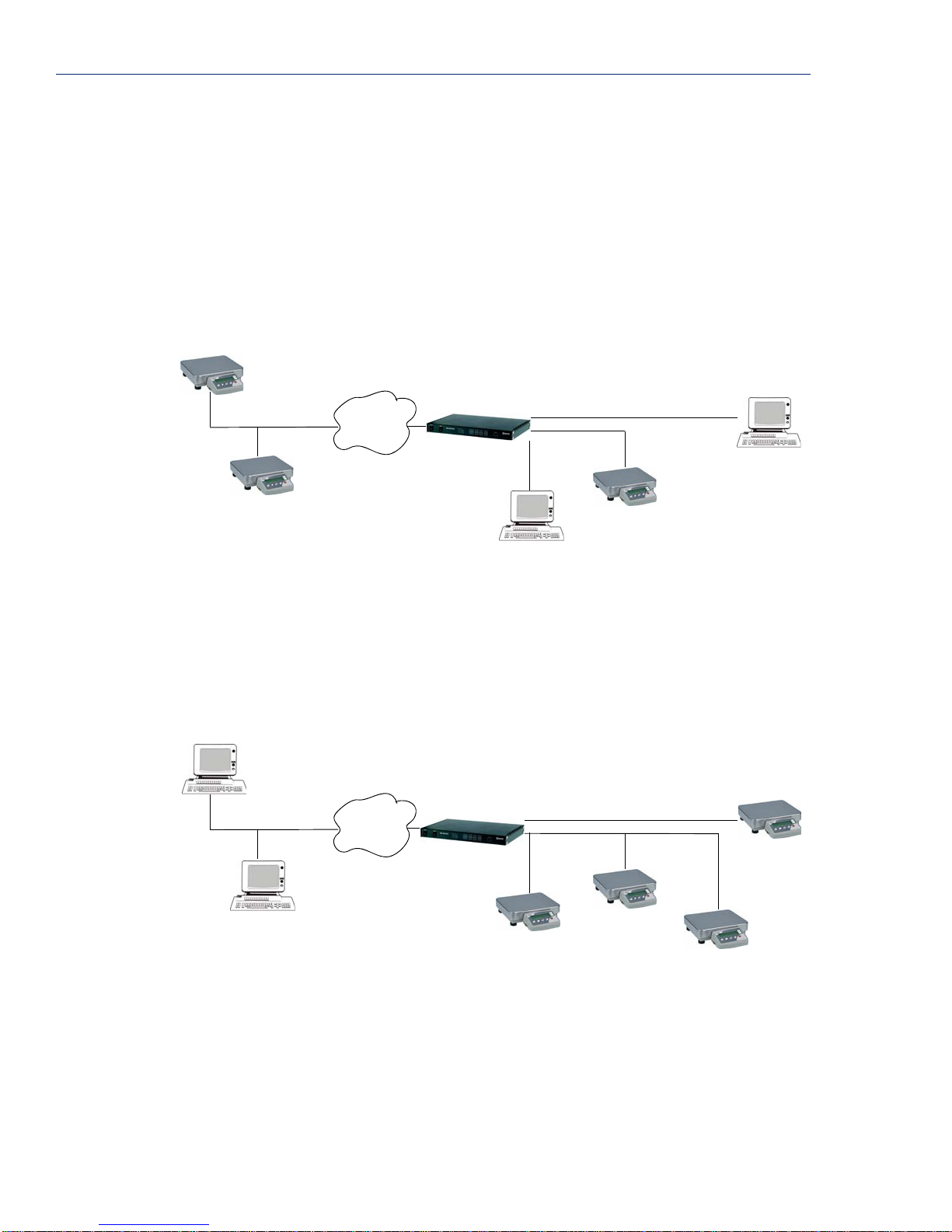
Modbus Configuration
Modbus Gateway Settings
The scenarios in this section are used to illustrate how the Modbus Gateway settings are incorporated
into a Modbus device environment. Depending on how your Modbus Master or Slave devices are
distributed, the Device Server can act as both a Slave and Master Gateway(s) on a multiport Device
Server or as either a Slave or Master Gateway on a single port Device Server.
Modbus Master Gateway
The Device Server acts as a Master Gateway when the Modbus Master resides on the serial side of
the Device Server. Each Modbus Master can communicate to UIDs 1-247.
Modbus Slave
TCP
Network
Master Gateway
Device Server
Serial
EIA-232
EIA-422/485
Modbus Master
Modbus Slave
Modbus Master
Modbus Slave
Modbus Slave Gateway
The Device Server acts as a Slave Gateway when the Modbus Master resides on the TCP/Ethernet
network and the Modbus Slaves reside on the serial side of the Device Server. Note that there is only
one Slave Gateway for the Device Server. You can define only one Slave Gateway for the Device
Server, although multiple lines/ports can participate as part of that gateway (depending on how you
configure the
Modbus Master
Modbus Master
Line Service settings).
TCP
Network
Slave Gateway
Device Server
Modbus Slave
Serial
EIA-232
EIA-422/485
Modbus Slave
Modbus Slave
Modbus Slave
78 IOLAN Device Server User’s Guide, Version 2.5
Page 79
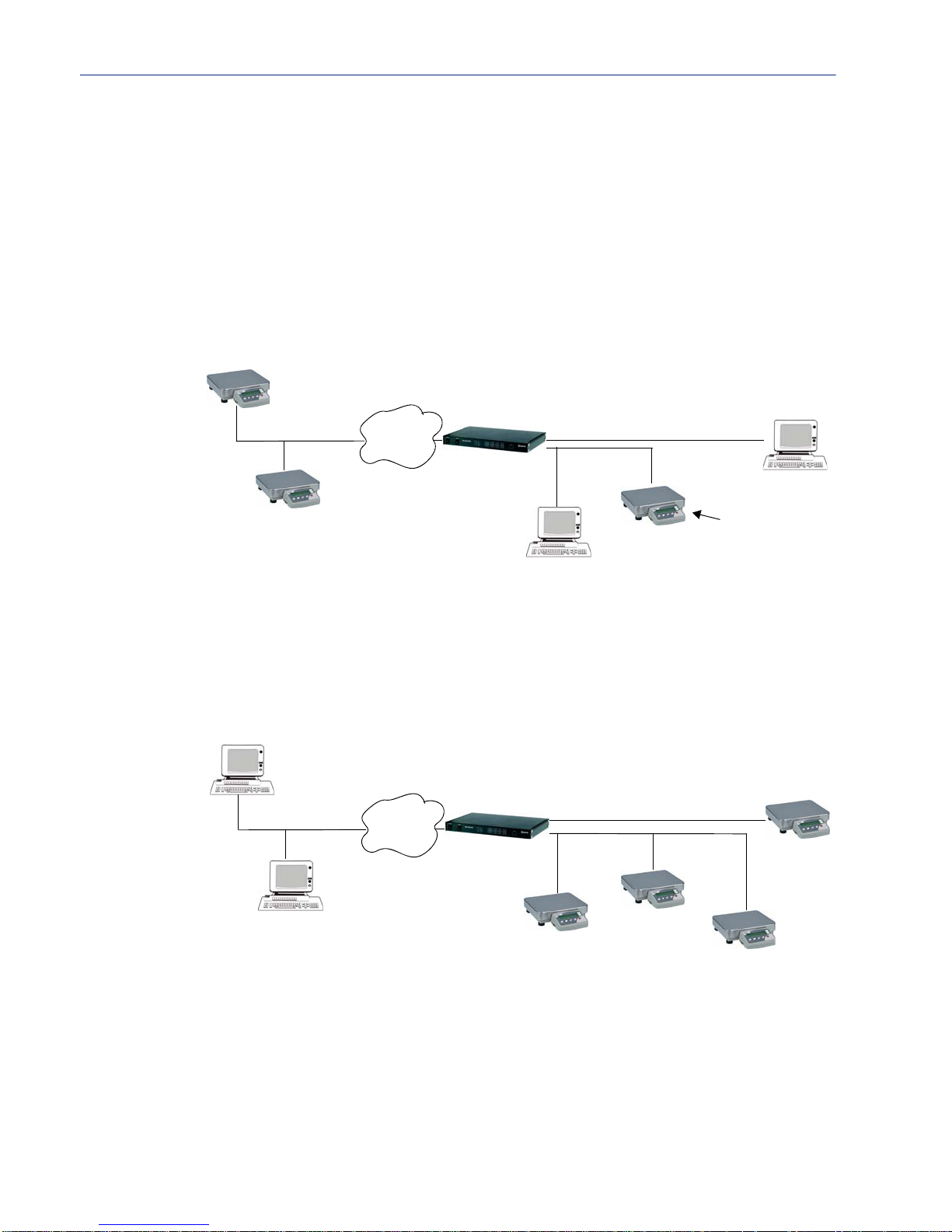
Modbus Line Settings
Modbus Master Settings
When you have Modbus Masters on the serial side of the Device Server, configure the Line as a
Modbus Master. If you also have a Modbus serial Slave on the same serial network as the serial
Modbus Master that communicates with that serial Master, do not define its UID in the Remote Slave
IP Mappings settings, or the Modbus serial Slave may not function properly. You must configure the
Modbus TCP Slaves (we term these as Remote Slave IP Mappings) on the TCP/Ethernet side so the
Device Server can properly route messages to the appropriate UIDs configured for those remote
Modbus TCP Slaves.
Modbus Slave
Modbus Configuration
TCP
Master Gateway
Network
Device Server
Serial
EIA-232
EIA-422/485
Modbus Master
Modbus Slave
Modbus Slave
Do not include
in Device Server
configuration
Modbus Master
Modbus Slave Settings
When you have Modbus Slaves on the serial side of the Device Server, configure the Line as a
Modbus Slave. There is only one Slave Gateway in the Device Server, so all Modbus serial Slaves
must be configured uniquely for that one Slave Gateway; all Modbus serial Slaves must have unique
UIDs, even if they reside on different serial ports, because they all must be configured to
communicate through the one Slave Gateway.
Modbus Master
TCP
Network
Slave Gateway
Device Server
Serial
EIA-232
EIA-422/485
Modbus Slave
Modbus Master
Modbus Slave
Modbus Slave
Modbus Slave
Configuring the Device Server 79
Page 80
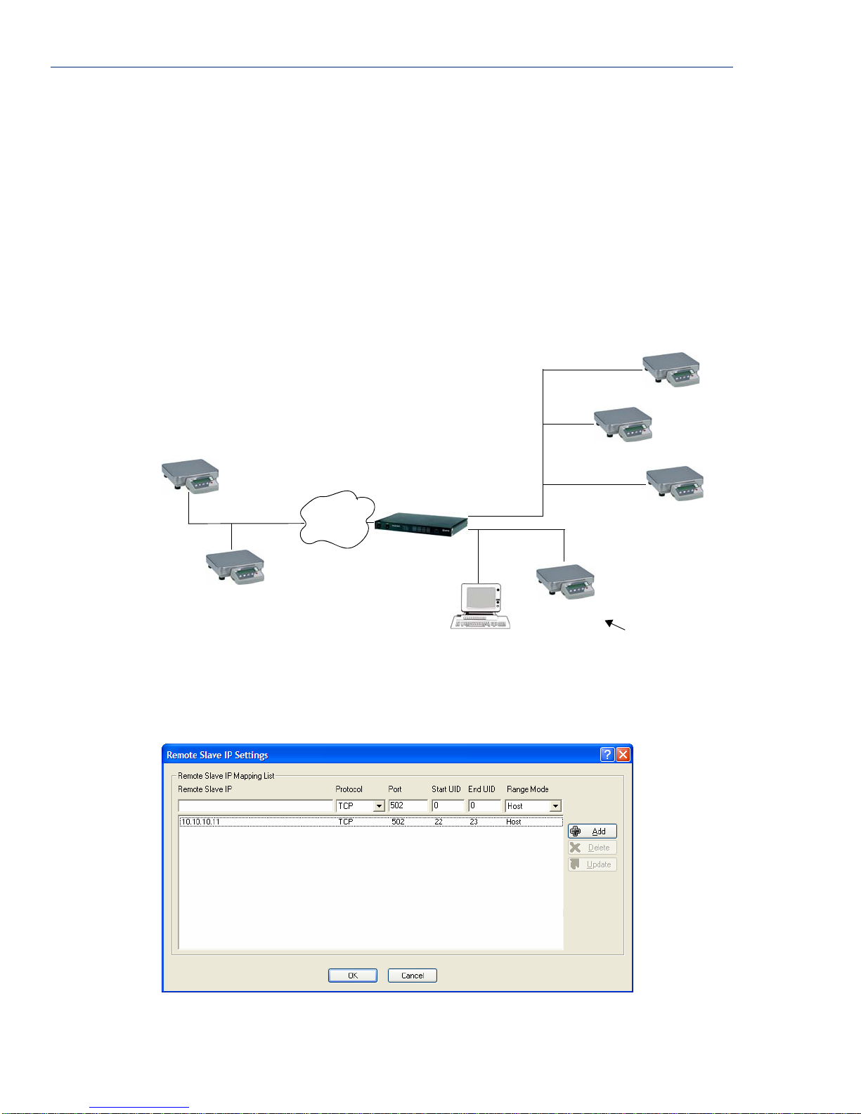
Modbus Configuration
Example Scenario
The following example describes the settings that you would configure to set up a Modbus
environment on a multiport Device Server, where the Modbus Master resides on a serial port/line
connected to the Device Server. This scenario assumes two things, that the
Modbus daemon) is enabled and that the default
The Modbus Master communicates with Modbus Slaves that reside on the TCP/Ethernet network and
on another serial port defined as part of the Slave Gateway in the Device Server, and with a Modbus
serial Slave (UID 10) that is on the same serial line as the Modbus Master itself. The Device Server
will act as a Master Gateway for the Modbus serial Master and allow it to communicate to the remote
Modbus TCP Slaves. By configuring the Device Server’s own IP address as a remote Modbus Slave
and having the Slave Gateway configured, the Modbus serial Master can communicate with Modbus
serial Slaves on another serial port/line on the Device Server (UIDs 6-8).
Modbus Slave
IP: 10.10.10.12
UID: 23
TCP
Network
Modbus Gateway settings have not been changed.
Master Gateway/Port 2
Slave Gateway/Port 1
Device Server
EIA-422/485
IP: 10.10.10.10
Service ModbusD (the
UID: 6
UID: 7
UID: 8
Modbus Slaves
Port 1
Port 2
Modbus Slave
IP: 10.10.10.11
UID: 22
Modbus Slave
Modbus Master
UID: 10
Do not include
in Device Server
configuration
When the Modbus Master is communicating with the TCP/Ethernet Modbus Slaves, the Line/port
that the Modbus Master is attached to must be configured with a
Line Service of Modbus Master.
By configuring the Remote Slave IP settings as:
80 IOLAN Device Server User’s Guide, Version 2.5
Page 81
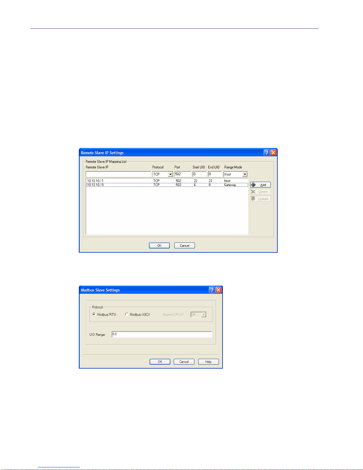
Modbus Configuration
The Device Server will send a request and expect a response from a Modbus Slave with an IP
Address of 10.10.10.11 on Port 502 with UID 22 and from Modbus Slave with and IP Address of
10.10.10.12 on Port 502 with UID 23 (remember when
Range Mode is set to Host, the Device
Server increments the last octet of the IP address for each UID specified in the range).
Also note that the Modbus Slave (UID 10) that is on the same line as the Modbus Master should not
be configured anywhere in the Device Server’s Master Gateway table for that serial port, or a Modbus
Exception may be sent (if this option is enabled) because the Device Server will attempt to connect
and send to a non-existent remote Modbus TCP Slave and a response timeout can occur.
To communicate with the Modbus Slaves on the serial side of the Device Server, the Device Server
must also be configured to be a Slave Gateway. The Modbus Slaves on a serial port attached to the
Device Server must be connected to a Line/port that is configured for the
Slave
. To communicate with the Modbus Slaves on the serial port configured as part of a Slave
Line Service of Modbus
Gateway, the Remote Slave IP settings are configured as:
The Device Server also acts as a Slave Modbus Gateway, receiving all the messages for IP address
10.10.10.10 and routing them to Modbus Slave devices with UIDs 6,7, and 8.
You must also configure the Line Service as Modbus Slave for the Modbus serial slaves as:
The Modbus serial Master will attempt to communicate through the Modbus Master Gateway to
Modbus serial Slaves with UIDs 6, 7, and 8. In order to accomplish this, the communication is routed
through the Device Server’s Modbus Slave Gateway from the Device Server’s Modbus Master
Gateway, to the serial Slaves.
Configuring the Device Server 81
Page 82
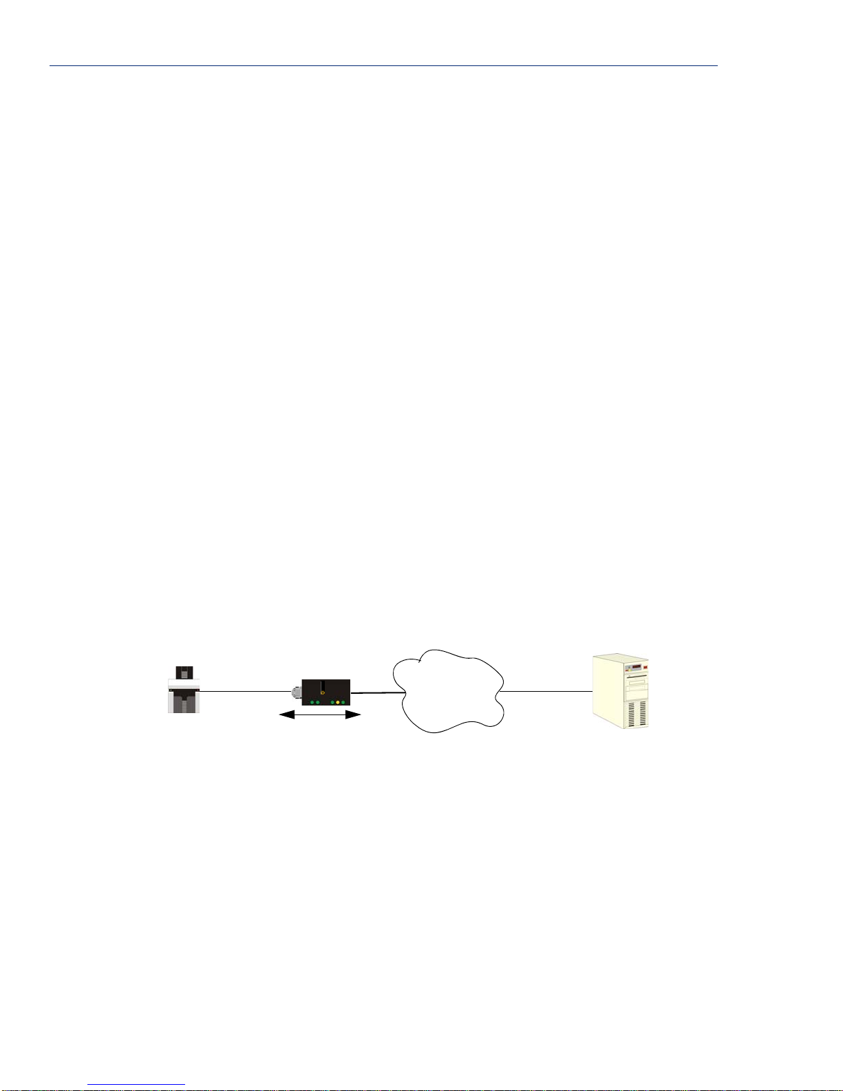
Email Notification
Email Notification
Email notification can be set at the Server and/or Line levels. You can set email notification at these
levels because it is possible that the person who administers the Device Server might not be the same
person who administers the serial device(s) attached to the Device Server port. Therefore, email
notification can be sent to the proper person(s) responsible for the hardware.
Email notification requires an SMTP host that is accessible by the Device Server to process the email
messages sent by the Device Server. When you enable email notification at the Server level, you can
also use those settings for the Line, or you can configure email notification specifically for each Line.
When you choose an event
select
Level Error, you will get notifications for all events that trigger Error, Critical, Alert, and
Emergency messages. The level order, from most inclusive to least inclusive, is as follows: Debug,
Info, Notice, Warning, Error, Critical, Alert, Emergency.
The following events trigger an email notification on the Server for the specified Level:
z Reboot, Alert Level
z Device Server Crash, Error Level
z Authentication Failure, Notice Level
z Successful Login, Downloads (all), Configuration Save Commands, Info Level
The following event triggers an email notification on the Line for the specified Level:
z DSR signal loss, Warning Level
z I/O alerts, Critical Level
Level, you are selecting the lowest notification level; for example, if you
Machine To Machine Connections
If you are using the Device Server to connect two hosts, allowing data to flow freely between them,
you just need to configure the
serial device is a security Card Reader that needs to transmit and receive information to/from a host
on the network that maintains the Card Reader’s application every time an employee uses an access
card to attempt to gain entry to the company.
Card
Device Server
Reader
After configuring the Server parameters (Server Name, IP Address, Ethernet and Serial interfaces,
etc.), the
Line Service is set to Sil Raw , which creates an automatic, continuous connection between
the Card Reader and its associated application on the Security host (though the Device Server), by
specifying the Security host name (which must already be configured in the Device Server’s Host
Table) and TCP/IP port number. Therefore, the Card Reader can make a request to the Security host
card reader application for employee verification, also logging access time, employee name, etc., and
the Security host application can send back a code that does or does not unlock the door.
Server and the Line (no User required). In the following example, the
perle
Network
Security
82 IOLAN Device Server User’s Guide, Version 2.5
Page 83

Users Connecting to Serial Devices
For a user to connect to the serial device connected to the Device Server from the LAN, the Line
Service
or go through the Easy Port Access Menu, depending on the
Users who are Level Admin or Normal will access the serial device directly; the user must connect to
the Device Server’s IP address and port number (the
login with a user name and password; if this is successful, the user is automatically connected to the
serial device.
Users who are Level Restricted or Menu can access the serial device through the Easy Port Access
Menu, which displays the line number and name and a logout option; the user just needs to connect to
the Device Server’s IP address. The user will be asked to login with a user name and password; if this
is successful, the Easy Port Access Menu is displayed. When a Menu-level user connects to the
Device Server using SSH, the Easy Port Access Menu will display only those lines that have been
configured for Reverse SSH. Similarly, if a Menu-level user connects using Telnet, the Easy Port
Access Menu will display only those lines that have been configured for Reverse Telnet. If the
Menu-level user connects using a protocol that is not configured on any of the Device Server’s lines,
nothing but
Line protocol must match.
must be set to Rev Telnet or Rev SSH. The user will either access the serial device directly
User Level setting.
DS Port parameter). The user will be asked to
Logout will be displayed on the Easy Port Access Menu; the connection protocol and the
Users Connecting to Serial Devices
Users Connecting to the LAN
For a user to connect to the LAN through the Device Server from a serial device, the Line Service
can be set to any
User accounts should be created when:
z authentication is being done locally by the Device Server.
z authentication is being done by an external authentication method, but there are settings that you
would like to ’pick up’ from the local user configuration. If you use RADIUS or TACACS+,
RADIUS/TACACS+ parameters overwrite
z you want to create predefined sessions for a user to limit that user’s access to the network.
z you have a user with a special use requirement, like a callback requirement.
Users can log into the Device Server without having a User set up, when external authentication is
being done. In this case, an externally authenticated user would inherit the
configuration while logged into the Device Server.
Connecting To the Device Server
When a user connects to the Device Server, that user can be authenticated either locally or externally
and is usually set up with predefined sessions or given the opportunity to configure a
access any host using any protocol (must have a
Session
respectively. So, user Dennis is authenticated by the Device Server (either locally or externally) and
then chooses to configure a
have attempted to access any host on the network).
). In this example, the user must have a Line and User Service of DSLogin and DSPrompt,
Direct or Silent setting, plus PPP, SLIP, Bidir, or DSLogin.
User parameters, which overwrite Line parameters.
Free Session to the HR_Server using the Telnet protocol (Dennis could
Default User
Free Session to
Level of at least Normal to configure a Free
Dumb Terminal
Dennis
User: Dennis
perle
Device Server
Network
Free Session: Telnet
HR_Server
Configuring the Device Server 83
Page 84
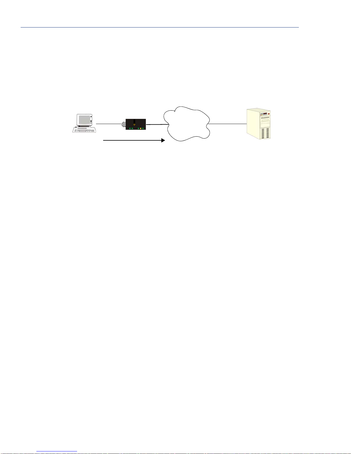
Setting Up Lines
Connecting Through the Device Server
When a user connects through the Device Server, that user can be authenticated either locally or
externally and is usually set up with a
successfully, passes the user onto the specified host. Therefore, the
and the
the
User Service is set to whatever protocol the user will use to access the host; in this example,
User Service is set to Telnet. When User Service Telnet is selected, the IP address of the
HR_Server is specified as the target Host IP. User Dennis will always have to log into the same server
with this configuration.
Dumb Terminal
Dennis
Setting Up Lines
Lines and ports are often used interchangeably. They are almost the same, that is, each line has an
associated port number (Line 1 starts with port 10001 by default), so port buffering settings are the
same as the buffering settings for the line.
How you set up a line is really determined by the device that is connected to the line. This section
goes over some of the common ways a line is used and things that you will want to keep in mind
when configuring the line.
perle
Device Server
User Service that, once authentication is completed
Line Service is set to DSLogin
Network
HR_Server
DSLogin
When you configure the Line for DSLogin, users connecting to the Device Server will have to go
through some form of authentication, either local or remote authentication. Regardless of whether a
user has been configured in the User table (local authentication) or is inheriting the Default User’s
attributes (remote or Guest authentication), when a
that connection (
DSLogin.
Telnet, Rlogin, SSH, SLIP, or PPP) will inherit the connection settings defined for
Direct/Silent/Reverse Connections
Direct connections bypass the Device Server, enabling the user to log straight into a specific host. A
direct connection is recommended where a user logging in to the Device Server is not required. It is
also recommended where multiple sessions are not a requirement. Direct connections require user
interaction: the message
session to the host is not initiated until
displayed. The message is redisplayed on logout.
Silent connections are the same as direct connections except that they are permanently established.
The host login prompt is displayed on the screen. Logging out redisplays this prompt. Silent
connections, unlike direct connections, however, make permanent use of pseudo tty (system)
resources and therefore consume host resources even when not in use.
Reverse connections enable a host on the network to establish a connection to a serial device through
the Device Server port.
Press return to continue is displayed on the user’s screen and the
User Service is selected (other than DSprompt),
Enter is pressed, after which the host login prompt is
84 IOLAN Device Server User’s Guide, Version 2.5
Page 85

Virtual Modems
Vmodem is a feature of the Device Server that provides “modem like” communication between two
Device Servers on a network or between a Device Server and a host. This feature behaves like two
modems connected across a telephone line. Typically, you use the
multiple devices communicating with a central site. With just a single IOLAN Device Server at each
end of the network, you don’t need to use multiple modems, avoiding the associated costs of calls and
connections.
The data is sent in raw format from the virtual modem and can be received by another Device Server
or a host. This data can be sent automatically using the
host and port number of the receiver; if the receiving side is also a Device Server, set the
Service
initiate bidirectional data flow) and the Device Server port that the data is coming in on (this should
match the port number on the sending Device Server). Or, you can manually start a connection by
typing
ip_address can be in IPv4 or IPv6 formats and is the IP address of the receiver. For example,
ATD123.34.23.43,10001 or you can use ATD12303402304310001, without any punctuation
(although you do need to add zeros where there are not three digits presents, so that the IP address is
12 digits long).
BIDIR
When you configure BIDIR, you are creating a bidirectional raw connection, meaning that the
connection can be initiated from either the Ethernet or serial side. The Device Server initiates TCP
connections to the configured host and port and listens for TCP connections on the
configured for the
Setting Up Lines
Vmodem feature when you have
Monitor DSR option and then configuring the
Line
to Rev Raw or Vmodem (Rev Raw if the Device Server is only receiving, Vmodem to
ATD<ip_address>,<port_number> and end the connection by typing +++ATH. The
DS Port
Line.
TruePort
Signal I/O
When you configure a line for TruePort, the Device Server provides a complete COM port interface
between the attached serial device and the network. You can also set the
which allows either the client or the Device Server to initiate communication. See
321 and the TruePort documentation for your operating system more information.
When you configure a line for Signal I/O, you are using the DSR, DCD, CTS, DTR, and RTS serial
pins for I/O channel digital input (DSR, DCD, and CTS) or digital output (DTR and RTS). Only after
Signal I/O is specified as the Line Service can you configure the serial pins for I/O.
Client Initiated option,
TruePort on page
Configuring the Device Server 85
Page 86
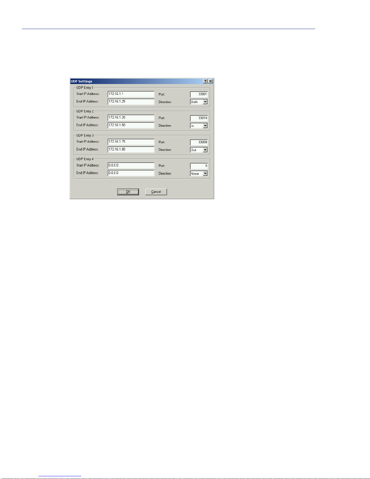
Setting Up Lines
UDP
When you configure UDP, you are setting up a range of IP addresses and a port number that you will
use to send UDP data to or receive UDP data from. For example:
The UDP configuration window, taken from the DeviceManager, is configured to:
z UDP Entry 1
All hosts that have an IP address that falls within the range of 172.16.1.1 to 172.16.1.25
and listen to
only receive UDP data from the hosts in that range with a source
z UDP Entry 2
Port 33001 will receive UDP data from the serial device. The serial device will
Port of 33001.
All UDP data received from hosts that have an IP address that falls within the range of
172.16.1.20 to 172.16.1.50 and Port 33010 will be sent to the serial device. The Device
Server will not send any data received on its serial port.
z UDP Entry 3
All hosts that have an IP Address that falls within the range of 172.16.1.75 to 172.16.1.80
and who listen to
Port 33009 will receive UDP data from the serial device. No UDP data will be
sent to the serial device.
z UDP Entry 4
This entry is disabled since Direction is set to None.
If Direction is set to In or Both, and Port is set to 0 (zero), the Device Server will learn a host IP
Address and Port number based on the first UDP packet it receives and will then only send and/or
accept UDP data from that host.
86 IOLAN Device Server User’s Guide, Version 2.5
Page 87
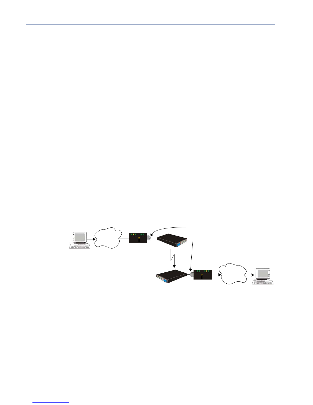
PPP Dial On Demand
If you want to configure a line to use PPP dial on demand, do the following:
1. Create an entry for the modem and its initialisation string.
2. Set the Line Service to PPP.
3. Set the Line Dial parameter to Out, enter the Phone Number that the modem will be calling, and
set the
Modem parameter to the modem you just added.
4. Set the Line Idle Timer to a value that is not zero (setting this value to zero creates a permanent
connection).
5. In the PPP configuration, enter either a Local and/or Remote IPv4 Address or a Local and/or
Remote IPv6 Interface Identifier and create a Host entry for either IP address/interface
identifier. Note that this IP address or interface identifier should be on its own unique network;
that is, not part of the local or remote networks.
In the example below, the local network has an IP address of 172.16.0.0/16 and the remote
network has an IP address of 204.16.0.0/16, so we arbitrarily assigned the
Address
created a
Address
6. Create a Gateway with Service as Network or Host with the host entry you just created. If you
want the connection to be able to reach any host is the remote network, set the
Network and specify the network IP address and subnet/prefix bits; if you want the connection to
go directly to a specific remote host, set the
In the example below, we created a Gateway entry using Host PPP_GW, assigned the Service as
Host (meaning that the connection will automatically go to a remote host), and provided the
Destination Address as 204.16.25.72.
Any traffic that goes through the gateway will automatically cause PPP to dial out.
Setting Up Lines
PPP Local IP
as 195.16.20.23 and the PPP Remote IP Address as 195.16.20.24. We also
Host entry, PPP_GW with IP Address 195.16.20.23 (the same as the PPP Local IP
).
Service to
Service to Host and specify the host’s IP address.
Local Host
172.16.0.0
Network
perle
Device Server
PPP Local IP Addr: 195.16.20.23
PPP Remote IP Addr: 195.16.20.24
204.16.0.0
perle
Network
Remote Host
204.16.25.72
Configuring the Device Server 87
Page 88

Setting Up Lines
Printers
Remote Printing Using LPD
When setting up a serial line that access a printer using LPD, do the following:
1. Set the Line Service to Printer and configure the Speed, Flow Control, Stop Bits, Parity, and
Bits parameters so that they match th e printer’s port settings.
2. Save your settings and kill the line.
3. Verify that LPD has been configured on the network host. To configure LPD on the network
host, you need to know the name or IP address of the Device Server and the print queue, either
raw_p<port_number> for a raw data connection or ascii_p<portnumber> for an ASCII
character connection. You can opt ionally append
<control d> or <form feed> to the end of the print job.
_d or _f to the queue name to add a
Remote Printing Using RCP
When setting up a serial line that accesses a printer using RCP, do the following:
1. Set the Line Service to Printer and configure the Speed, Flow Control, Stop Bits, Parity, and
Bits parameters so that they match th e printer’s port settings.
2. Save your settings and kill the line.
3. T o execute a print job, use the following syntax:
rcp filename/ip_address DeviceServerName:p<#>
SSL/TLS
where <#> is the Device Server line port number (DS Port).
Remote Printing Using Host-Based Print Handling Software
Printers connected to the Device Server can be accessed by TCP/IP hosts using print handling
software.
1. Set the Line Service to Rev Raw and configure the Speed, Flow Control, Stop Bits, Parity, and
Bits parameters so that they match th e printer’s port settings.
2. Save your settings and kill the line.
3. The print handling software needs to know the Name of the Device Server and the DS Port
number assigned to the printer port.
You can create an encrypted connection using SSL/TLS for any of the raw data line options: any Raw
settings,
There is an extensive selection of SSL/TLS ciphers that you can configure for your SSL/TLS
connection; see
enable peer certificate validation, for which you must supply the validation criteria that was used
when creating the peer certificate (this is case sensitive, so keep that in mind when enabling this
option).
BIDIR, or VModem. You can set up the Device Server to act as an SSL/TLS client or server.
Modbus Gateway Settings on page 78 for a list of SSL/TLS ciphers. You can also
88 IOLAN Device Server User’s Guide, Version 2.5
Page 89
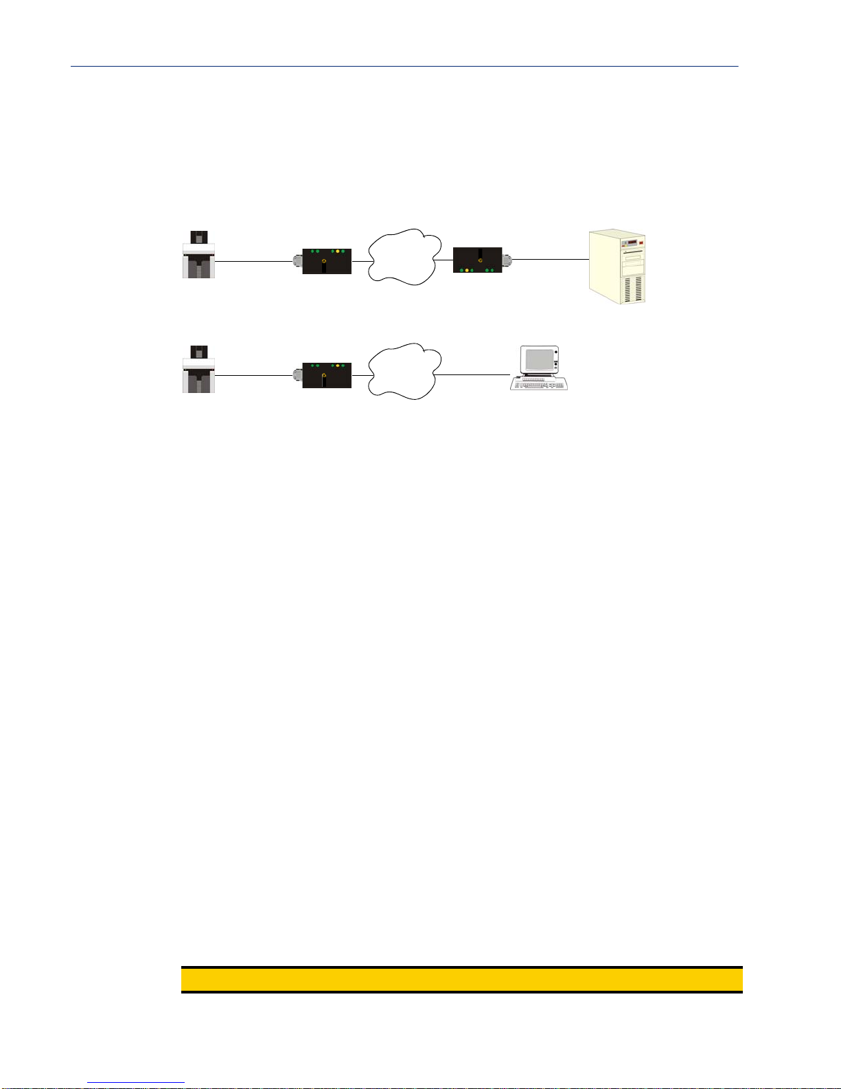
Serial Tunnel Settings
The purpose of the serial Line Service Client/Server Tunnel is to allow two Device Servers that are
connected back-to-back over Ethernet to virtually link two serial ports, based on RFC 2217. The
serial device that initiates the connection is the
although once the serial communication tunnel has been successfully established, the tunnel will stay
connected and communication can go both ways.
Setting Up Users
Client Tunnel and the recipient is the Server Tunnel,
Serial
Server
Tunnel
Device Server
The Server Tunnel will also support Telnet Com Port Control protocol as detailed in RFC 2217.
Serial
Server
Tunnel
Device Server
The port signals will also follow the signals on the other port. If one port receives DSR then it will
raise DTR on the other serial port. If one port receives CTS then it will raise RTS on the other port.
The CD signal is ignored.
Setting Up Users
You can create up to four users, in addition to the Admin user (who cannot be deleted) on all desktop
Device Server models. On rack mount models, you can create up to 48 users, in addition to the
Admin user (who cannot be deleted).
A user can even represent a device, like a barcode or a card swipe device, that you want to be
authenticated.
perle
Network
perle
Device Server
perle
Network
Serial
Client
Tunnel
Running
2217 Application
User Accounts
When a serial device (like a dumb terminal or a barcode reader) is trying to access a host through the
Device Server, you can configure user accounts when users:
z are authenticated by the Device Server (either locally or by an external authentication server) and
z want a single or multiple session(s) to a network host; here they initially login to the Dev ice
z need a profile different from the Default user profile.
When a host is accessing a serial device (like a modem or a server), you can configure user accounts
where users:
z are being provided a remote access service, like a SLIP or PPP connection, and they are being
z are using a reverse telnet connection to manage a UNIX server or a router and want to be
z are using reverse SSH to connect to the Device Server not as a Guest user.
z need a profile different from the Default user profile.
Note:
then connect to a network host.
Server before starting that session. The Device Server is used to configure and start the session.
locally authenticated by the Device Server.
authenticated.
You do not need user accounts for users who are externally authenticated.
Configuring the Device Server 89
Page 90

Setting Up Users
User Levels
There are four User Levels: Admin, Normal, Restricted, and Menu. Setting up users is only
necessary when the users are actually connecting to the Device Server. Oftentimes, the Device Server
is used as a gateway to a network and the user never actually logs into the Device Server itself. Users
who do log into the Device Server (
will have to navigate by either the Menu or CLI (except for users with
Line Service set to DSLogin and User Service set to DSPrompt)
Menu privileges, who can only
use the Menu).
z Admin—Users with Admin privileges have full administrative access to the IOLAN Device
Server. This is not the same as the Admin user, but has equal authority (the Admin user is a
permanent, factory-set user on the IOLAN Device Server).
z Normal—Users with Normal privileges have access to the Sessions menu and associated CLI
only . They can start sessions, define and predefine sessions, and can change their own user
environment.
z Restricted—Users with Restricted privileges have access to a restricted Sessions menu and
associated CLI; they can only open sessions predefined for them by the Admin user, but not alter
their own environment or sessions. Predefined sessions can also be configured to start
automatically at login.
z Menu—Users with Menu privileges have access to predefined session. All other functionality is
unavailable.
When the Admin user logs into the Device Server, the prompt ends with a #, whereas all other users’
prompts ends with a
$ or £, depending on the character set.
Sessions
Sessions are defined for users who are coming in through a serial device and are connecting to a host
on the LAN.
Users who have successfully logged into the Device Server (User Service set to DSprompt) can start
up to four login sessions on LAN hosts. These users start sessions through the Menu option
Sessions.
Multiple sessions can be run simultaneously on the same host or on different hosts. Users can switch
between different sessions and also between sessions and the Device Server using hotkey commands.
Users with Admin or Normal privileges can define new sessions and connect through them, even
configure them to start automatically on login to the Device Server.
Restricted and Menu users can
only start sessions predefined for them by the Admin user.
Users can be configured to have access to a specific port and access modes for this port, such as
Read/Write (RW), Read Input (RI), Read Output and Read Both (RI & RO).
Users Connecting from LAN to Device Server to Serial Device
Easy Port Access Menu
The Easy Port Access Menu is displayed when a Restricted or Menu level user logs into the box
from the Ethernet side (
Easy Port Access Menu displays the line number, line name, line protocol (either
rev-ssh), and a logout option. You can only access a line if it has the same connection protocol as
the one you used to log into the Device Server. So, if you used SSH to log into the Device Server and
the
Line Service is set for Rev Telnet, you will not be able to access the serial device connected to
that line.
Line Service set to Rev Telnet or Rev SSH) to access a serial device. The
rev-tel or
90 IOLAN Device Server User’s Guide, Version 2.5
Page 91

Setting Up Users
Reverse Sessions and Multisessions
(2 Port+ only) The interaction between reverse sessions and multisessions is somewhat complex, so
the definition of each parameter is provided to give you a context for their interaction.
Reverse Session—The definition of a Reverse Session is a TCP connection to a TCP port (defined in
the Line configuration as the
or
Reverse Raw. Other LAN to Device Server connections, such as the connection to the well-known
Telnet or SSH ports (the management TCP ports of 23 for Telnet and 22 for SSH), do not count as
reverse sessions.
Reverse Session Limit—This server parameter is the maximum number of Reverse Sessions (as
defined above) that can be active on the Device Server at any given moment. This value is
completely independent of the Line
maximum of 20, that only says that the total number of reverse sessions cannot exceed 20; it says
nothing about total number of reverse sessions per line, total number of active line, etc.
The minimum value is 1. The maximum value is determined as follows:
1. Add up all the serial ports, internal modems, and PCI slots in the Device Server. This number
equals the maximum number of lines available on the Device Server.
2. If the maximum number of lines is less than 4 exclusive (that is, 1, 2, or 3), then multiply that
number by 4 to obtain the maximum Server
maximum number of lines by 2 to obtain the maximum Server
Multisessions—The Line Multisessions limit is the number of additional reverse sessions (beyond
the first reverse session) allowed on the line. Therefore, if this number is set to 5, the total number of
reverse sessions allowed on the line is 5+1 or 6.
The default and minimum value is 0, which means that reverse Multisessions is disabled and you
only get the 1 default reverse session; therefore, the maximum value is the maximum
Reverse Session Limit
Reverse Session Security—If this Line parameter is enabled, the user must login when making a
Reverse Telnet connection to a configured DS Port (the TCP port associated with the line that is
configured for a reverse connection). If the line is configured for
redundant, because a login is always required when SSH is specified.
So, in order to make multiple reverse connections to a line, the line must be configured to log users in
so the user’s Line Access Rights can be obtained from the User profile (regardless of whether that
profile comes from a defined User, the Default User’s settings, or is passed to the Device Server from
TACACS+ or RADIUS). This means that one of the following conditions have been met:
z The line is configured for Reverse Telnet and Reverse Session Security is enabled.
z The line is configured for Reverse SSH.
If users are connecting to the Device Server by the management TCP port (or well-known port of 23
for Telnet and 22 for SSH), they always have to login to the Device Server and depending on their
access level can get:
admin—standard CLI/Menu with admin privileges
normal—standard CLI/Menu with normal privileges
restricted—Easy Port Configuration Menu
menu—Easy Port Configuration Menu
If users are connecting to the Device Server by the IP address and configured DS Port (for example,
the line has a configured
telnet 101.170.12.15 88 command), a line set up for Reverse Telnet would require a login if
Reverse Session Security is enabled, otherwise, the User settings would dictate what the user sees.
For
Reverse SSH, the user always has to login to the Device Server.
DS Port) on a line that is configured for Reverse Teln et, Reverse SSH,
Multisessions number. If the Reverse Session Limit is set to a
Reverse Session Limit, otherwise, multiply the
Reverse Session Limit.
Server
-1.
Reverse SSH, this option is
DS Port of 88, so the user would connect with the
Configuring the Device Server 91
Page 92

Configuring Network Options
Configuring Network Options
Hosts
This is probably one of the first Device Server options you want to configure, since so many other
configuration options require a preconfigured host. You can use any host name you want, since the
host name is used only by the Device Server. You can configure up to 20 hosts using IPv4 or IPv6
internet addresses on desktop Device Server models; you can configured up to 49 hosts on rack
mount Device Server models.
Gateways
Gateways are hosts that connect Local Area Networks (LANs) together. If you want to access a host
that isn’t on your local network, you will be connected via a gateway. Gateways route data via other
gateways until the destination local network is reached. There are three types of gateways:
z Default—A gateway that provides general access beyond your local network.
z Host—A gateway reserved for accessing a specific host external to your local network.
z Network—A gateway reserved for accessing a specific network external to your local network.
You can specify up to 20 gateways on desktop Device Server models; you can specify up to 58
gateways on rack mount Device Server models.
RIP
The Routing Information Protocol (RIP) is a routing protocol used with almost every TCP/IP
implementation. Its function is to pass routing information from a router or gateway to a
neighbouring router(s) or gateway(s). RIP messages contain information about destinations which
can be reached and the number of hops which are required. The hop-count is the basic metric of RIP
and so RIP is referred to as a ’distance vector protocol’. RIP messages are carried in UDP datagrams.
RIP for Clients Configuration and Operation
The administrator can selectively advertise networks remotely connected via a SLIP/PPP link on the
Ethernet connection, and pass RIP routing information to remotely connected clients. As this can be
undesirable in some environments, this behavior is configurable and is defaulted to the non-routing
behavior.
Additional PPP and SLIP Functionality - RIP Packet Exchange
Transmission and reception of Routing Information Protocol (RIP) packets over PPP and SLIP
connections can be configured on a per user basis or on a per line basis. The
associated with a line and each local user determines the exchange of RIP packets between the
Device Server and remotely connected users connected from the serial side. For a user authenticated
by RADIUS, the
The administrator has four options for setting the routing and Framed-Routing parameters:
z None—Routing information is not exchanged across the link. This is the default setting for a line
and a locally defined user.
z Send—Routing information is only transmitted to the remote user.
z Listen—Routing information is only received from the remote user.
z Send and Listen—Routing information is transmitted to and received from the remote user.
The setting for the Line Routing parameter is the default for a connection, but the setting for the local
User Routing parameter or RADIUS Framed-Routing parameter is used if this differs from the Line
Routing
parameter.
Framed-Routing parameter determines the exchange of RIP packets.
Routing parameter
92 IOLAN Device Server User’s Guide, Version 2.5
Page 93

DNS/WINS
You can configure up to four DNS and four WINS servers. You can configure WINS servers for
PPP-client name resolution and DNS servers for PPP-client name resolution and Device Server host
name resolution (for example, when specifying
Syslog
The Device Server can be configured to send system log messages to a syslog daemon running on a
remote host if the
the syslog information and specify the level for which you want syslog information sent.
Syslog service is activated. You can configure a primary and secondary host for
SNMP
If you are using SNMP to manage/configure the Device Server, or to view statistics or traps, you
must set up a User in SNMP version 3 or a Community in SNMP version 1,2 to allow your SNMP
manager to connect to the Device Server; this can be done in the DeviceManager, WebManager, CLI,
or Menu. You must then load the perle-sds.MIB (found on the CD-ROM packaged with the Device
Server) file into your SNMP manager before you connect to the Device Server.
Configuring Time
Configuring Time
Bootup file).
The Device Server has a real-time internal clock, allowing the date and time to be set and viewed. It
will maintain the time over a short power outage and after reboots of the Device Server. If you do not
set the time, it will start the clock at the factory set time.
Setting the Device Server’s Time
When you set the Device Server’s time, the connection method and time zone settings can affect the
actual internal clock time that is being set. For example, if you are connecting to the Device Server
through the DeviceManager and your PC’s time zone is set to Pacific Standard Time (GMT -8:00)
and the Device Server’s time zone is set to Eastern Standard Time (GMT -5:00), the Device Server’s
time is actually three hours ahead of your PC’s time. Therefore, if you set the Device Server’s time to
2:30 pm in the DeviceManager (Tools, Set Unit Da te/Time), the Device Server’s actual internal
clock time is 5:30 pm. This is the only configuration method that interprets the time and converts it
between time zones, as necessary.
All other configuration methods set the Device Server’s internal clock time to the time specified, with
no interpretation.
Time Settings
You can set standard and summer time (day light savings time) in the Device Server. You can specify
the summer time settings as absolute, on a fixed date and time, or relative, on something like the third
day of the third week at this time in June.
SNTP
You can configure your SNTP client in the Device Server to automatically synchronize the Dev ice
Server’s time.
Configuring the Device Server 93
Page 94
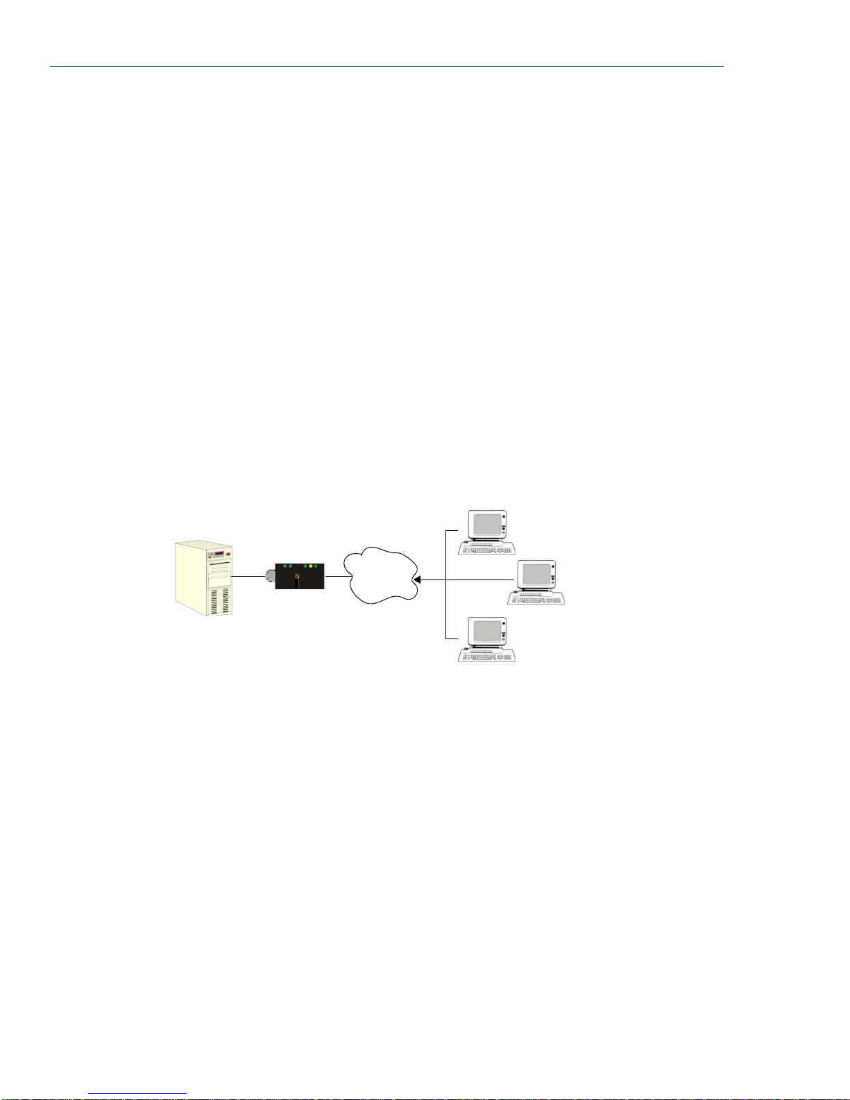
Keys and Certificates
Keys and Certificates
When you are using SSH, SSL/TLS, LDAP, or HTTPS, you will need to install keys and/or
certificates or get server keys in order to make those options work properly. All certificates need to be
created and all keys need to be generated outside of the Device Server, with the exception of the
Device Server SSH Public keys, which already exist in the Device Server. SSH keys must be
generated using the OpenSSH format.
Certificate Authorities (CAs) such as Verisign, COST, GTE CyberTrust, etc. can issue certificates. Or,
you can create a self-signed certificate using a utility such as OpenSSL.
SSH
When you are using the SSH connection protocol, keys need to be distributed to all users and the
Device Server. Below are a couple of example scenarios for key/certificate distribution.
Users Logging into the Device Server Using SSH (Reverse)
In the following example, users are connecting to the Device Server via SSH from the LAN.
Therefore, the following keys need to be exchanged:
z Upload the Device Server SSH Public Key to each user’s host machine who is connecting and
logging into the Device Server using SSH.
z Download the SSH Public Key from each user’s host machine who is connecting and logging
into the Device Server using SSH.
Server
perle
Network
Device Server
Device Server Private Key
Lynn Public Key
Tracy Public Key
Dennis Public Key
SSH
Lynn
Device Server Public Key
Lynn Private Key
Tracy
Device Server Public Key
Tracy Private Key
Dennis
Device Server Public Key
Dennis Private Key
94 IOLAN Device Server User’s Guide, Version 2.5
Page 95
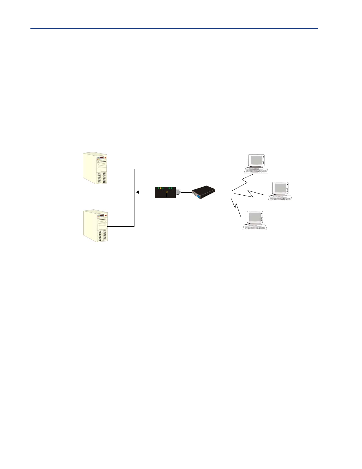
Keys and Certificates
Users Passing Through the Device Server Using SSH (Dir/Sil)
In the following example, users are connecting to servers on the LAN through a serial device (a
modem). The
first log into the Device Server and then are connected to a specified host (configured for the user
when
User Service SSH is selected) through an SSH connection. Lynn and Tracy automatically
connect to the HR Server and Dennis automatically connects to the Development Server via SSH
through the Device Server. All the SSH negotiation is being done between the Device Server and the
target servers, therefore, the following keys need to be exchanged:
z Download the SSH Host Public Key to the Device Server for each of the hosts that the Device
Server is connecting to.
z Download the SSH User Private Key for each user whose User Service is set to SSH.
z Copy the SSH User Public Key to the host that the user is connecting to (this is done outside the
scope of the Device Server).
Line Service is set to DSLogin and the User Service is set to SSH, therefore, users
Lynn
LDAP
HTTPS
Sales Server
Sales Server Private Key
Dennis Public Key
SSH
perle
Device Server
Sales Server Public Key
HR Server Public Key
Lynn Private Key
Tracy Private Key
Dennis Private Key
Dennis
Tracy
HR Server
HR Server Private Key
Lynn Public Key
Tracy Public Key
If you are using LDAP external authentication, you must download a CA list to the Device Server
that includes the certificate authority (CA) that signed the LDAP certificate on the LDAP host. See
Keys and Certificates on page 94 for more information.
If you are using the WebManager in secure mode (HTTPS), you need to download the SSL/TLS
private key and certificate to the Device Server. You also need to set the
with the same password that was used to generate the key. See
Keys and Certificates on page 94 for
SSL Passphrase parameter
more information.
SSL/TLS
You can configure the SSL/TLS server to encrypt data that is sent between the Device Server and an
SSL/TLS client. You can configure the cipher combinations that you want the connection to use and
configure peer validation, if you want to use it.
Configuring the Device Server 95
Page 96

Language support
Language support
T wo language files, in addition to English, are supplied on the supplemental CD, French and German.
You can use any of these language files to create a translation into a language of your choice. You can
download the language file (whether the language is supplied or translated) into the Device Server
and select the
WebManager field labels display in your language.
You can view Menu, CLI, or WebManager in one other language only (as well as English). If you
download another language file, this new language will replace the first language you downloaded.
You can revert to English at any time; the English language is st ored permanently in the Device
Server and is not overwritten by your new language. Each user logged into the Device Server can
operate in either English or the downloaded language.
Loading a Supplied Language
This section describes how to download a language file using the CLI, since it is the least intuitive
method. French and German language files are provided on the supplemental CD.
T o load one of the supplied languages into the Device Server, so the Menu, CLI and WebManag er
fields appear in another language, do the following:
1. Open the supplemental CD and identify the language file, either Iolan_ds_French.txt or
Iolan_ds_German.txt, or supply one of your own translated files.
2. Copy the language file to a host machine on the network; place it in the main file system or on
the main hard drive.
3. Either use the TFTP defaults in the Device Server or, configure as necessary, TFTP in the Device
Server.
4. In the CLI of the Device Server, enter the host IP address and file name; for example,
netload customlang 172.16.4.1 / temp/Iolan_ds_ French.txt
Language option of Customlang (custom language), making the Menu, CLI, and
The Device Server will download the language file via TFTP.
5. To set an individual user to the new language, go to the Users menu and, in the Language field
select
Customlang. In the CLI (only) you can set individual users or all users to the new
language; see the
6. The user will see the change of language when he/she logs out (Main Menu, Sessions Menu,
Logout) and logs back into the Device Server. If, as Admin user, you change your language
setting to
and exit the
language.
Note:
Customlang, you will see the text menus display in the new language when you save
If you download a new software version, you can continue to use your language unchanged;
however, we recommend translating the new strings, which will be added to the end of the
language file. A
On successful download, the Customlang in the Device Server will be overwritten by the
new language.
set user * command.
Change User form. Users with Level Normal can also change their display
Reset to Factory Defaults will reload the Customlang as English.
96 IOLAN Device Server User’s Guide, Version 2.5
Page 97

Translation Guidance
To help you with your translation, of supplied ASCII text language files we offer the following
guidance:
z The Device Server will support languages other than English (and the supplied German and
French languages). The English language file,
each line at the beginning of the line. If a translated line goes over that character length, it will be
displayed truncated in the Menu, CLI, or WebManager.
z Translate line for line, do not omit lines if you do not know the translation; leave the original
untranslated text in place. Also, you must maintain the same sequential order of lines. It is a good
practice to translate the file using a text editor that displays line numbers, so you can periodically
verify that the line sequence has not changed from the original file (by comparing it to the
original file).
z Keep all translations in quotes, otherwise the line will not display properly.
z Each line must end with a carriage return.
z If a line contains only numbers, for example 38400, leave that line in place, unchanged (unless
you are using a different alphabet).
Software Upgrades and Language Files
If you receive a software upgrade for the Device Server, the language files supplied on the
supplemental diskette/CD might also have been updated. We will endeavour to provide a list of those
changes in another text file on the same supplemental CD.
Language support
english.txt, displays the character length of
Note:
The upgrade of your software (firmware) will not change the display of the language in the
Menu, CLI, or WebManager.
If you are already using one of the supplied languages, French or German, you probably want to
update the language file in the Device Server. Until you update the Device Server with the new
language file, new text strings will appear in English.
If you are already using a language translated from an earlier version, you probably want to amend
your translation. When a language file is updated, we will try to maintain the following convention:
1. New text strings will be added to the bottom of the file (not inserted into the body of the existing
file).
2. Existing text strings, if altered, will be altered in sequence; that is, in their current position in the
file.
3. The existing sequence of lines will be unchanged.
4. Until you have the changes translated, new text strings will appear in the Menu, CLI, or
WebManager in English.
Configuring the Device Server 97
Page 98

Downloading Terminal Definiti ons
Downloading Terminal Definitions
All terminal types can be used on the Device Server. Some terminal types which are not already
defined in the Device Server, however, are unable to use Full Screen mode (menus) and may not be
able to page through sessions properly. When installed, the Device Server has several defined
terminal types—Dumb, WYSE60, VT100, ANSI, TVI925, IBM3151, VT320, and HP700.
If you are not using, or cannot emulate, any of these terminal types, you can add up to three
additional terminal definitions to the Device Server. The terminal definitions can be downloaded
from a TCP/IP host.
To download terminal definitions, follow these steps:
1. Decide which TCP/IP host you are going to use. It must be a machine with enabled.
2. Configure TFTP in the Device Server as necessary.
3. Download the new terminal definition to the Device Server as Term1, Term2, or Term3.
4. In the Line configuration, select the Terminal Type Termx that you custom defi ned.
Creating Terminal Definition Files
To create new terminal definition files, you need to copy and edit the information from the terminfo
database.
1. On a UNIX host, change directory to /usr/lib/terminfo/x (where x is the first letter of the
required terminal type). For a Wyse60, for example, you would enter the command
cd /usr/lib/terminfo/w.
2. The termcap files are compiled, so use the command infocmp termfile to read the required
file (for example:
3. Check the file for the attribute xmc#n (where n is greater than or equal to 1). This attribute will
corrupt menu and form displays making the terminal type unsuitable for using Menu mode.
4. If the terminal definition is suitable, change to a directory of your choice.
5. Rename and copy the file to the directory specified at step 4. using the command
infocmp termfile > termn where n is greater than or equal to 1; (for example,
infocmp wy50 > term1). Make sure the file has global read and execute permission for its
entire path.
6. Edit the file to include the following capabilities in this format:
infocmp wy60).
term=
acsc=
bold=
civis=
clear=
cnorm=
cup=
rev=
rmacs=
rmso=
smacs=
smso=
page=
circ=
98 IOLAN Device Server User’s Guide, Version 2.5
Page 99

For example:
term=AT386 | at386| 386AT |386at |at/386 console
acsc=jYk?lZm@qDtCu4x3
bold=\E[1m
civis=
clear=\E[2J\E[H
cnorm=
cup=\E[%i%p1%02d;%p2%02dH
rev=\E4A
rmacs=\E[10m
rmso=\E[m
smacs=\E[12m
smso=\E[7m
page=
circ=n
Downloading Terminal Definitions
Note:
As you can see from the example, capabilities which are not defined in the terminfo file must
still be included (albeit with no value). Each entry has an 80 character limit.
On some versions of UNIX, some of the capabilities are appended with a millisecond delay
(of the form $<n>). These are ignored by the Device Server and can be left out.
The ‘acsc’ capability, if defined, contains a list of character pairs. These pairs map the
characters used by the terminal for graphics characters to those of the standard (VT100)
character set.
Include only the following character pairs:
jx, kx, lx, mx, qx, tx, ux and xx
(where x must be substituted by the character used by the terminal). These are the
box-drawing characters used to display the forms and menus of Menu mode. They must be
entered in this order.
The last two capabilities will not be found in the terminfo file. In the page field you must
enter the escape sequence used by the terminal to change screens. The
whether the terminal can use
y or n. These capabilities can be found in the documentation supplied with the terminal.
to
previous page and next pa ge control sequences. It must be set
circ field defines
Configuring the Device Server 99
Page 100

TFTP Configuration
TFTP Configuration
Note:
TFTP can be configured for two unique transfer operations:
1. Between the DeviceManager and a Device Server. This configuration is accessed by selecting
2. Between the Device Server and a host. This configuration is accessed by selecting Network,
You must have a TFTP server running on any host that you are uploading or downloading files
to/from. If you are using the DeviceManager and transferring a local file to a Device Server, you still
need to have a TFTP server running on your PC. When you specify the file path, the path must be
relative to the default path set in your TFTP server software.
TFTP file transfers send via UDP packets. When the packet delivery is interrupted for any
reason and a timeout occurs, that packet is resent if the retry count allows it. Therefore, if a
very large file is being transferred and is interrupted, the entire file is not resent, just the part
of the file and was not received.
Tools, Options from the DeviceManager’s tool bar. You can specify the number of times the
DeviceManager’s TFTP server retries a file transfer to a Device Server, how many seconds the
TFTP process will wait (timeout) before retrying to transfer a file, and the UDP port that will be
used for the file transfer between the DeviceManager and the Device Server. (DeviceManager
only.)
TFTP in the DeviceManager, by typing set server tftp in the CLI, by selecting Network
Configuration
SNMP MIB, or by selecting
of times the Device Server’s TFTP client retries a file transfer to a host and how many seconds
the TFTP process will wait (timeout) before retrying to transfer a file.
, TFTP from the Menu, by selecting ServerInfo, tftpRetry and tftpTimeOut in the
Network, TFTP in the WebManager. You can configure the number
Resetting Configuration Parameters
You can reset the Device Server to its factory settings through any of the following methods:
z You can push in the recessed button at the back of the Device Server hardware for more than
three seconds (pushing it in and then quickly releasing will just reboot the Device Server)
z DeviceManager, select Tools, Reset to Factory Default s
z CLI, at the command line type, reset factory
z WebManager, click the Factory Defaults button
z Menu, select Network Configuration, Reset to Factory Defaults
z SNMP, in the adminInfo folder, Set the adminFunction variable to 2
Lost Admin Password
If the Admin user password is lost, there are only two possible ways to recover it:
z reset the Device Server to the factory defaults
z have another user that has admin level rights, if one is already configured, reset the Admin
password
100 IOLAN Device Server User’s Guide, Version 2.5
 Loading...