

Page 1
IDS-509GPP Switches Quick Start Guide P/N 5500400-10 (Rev A) Version #A1.16.03.2017
IDS-509GPP Switches
Quick Start Guide
___________________________________________________
This guide covers basic installation and configuration and is intended for first time
setup or product evaluation.
Complete details can be found in the following guides at www.perle.com/downloads.
• IDS-509GPP Hardware Installation Guide
• IDS Managed Switches User Guide – Pro Feature Set
• IDS Managed Switches CLI Guide – Pro Feature Set
What’s in the box?
• The IDS switch
• Quick Start Guide (this document)
Hardware Overview
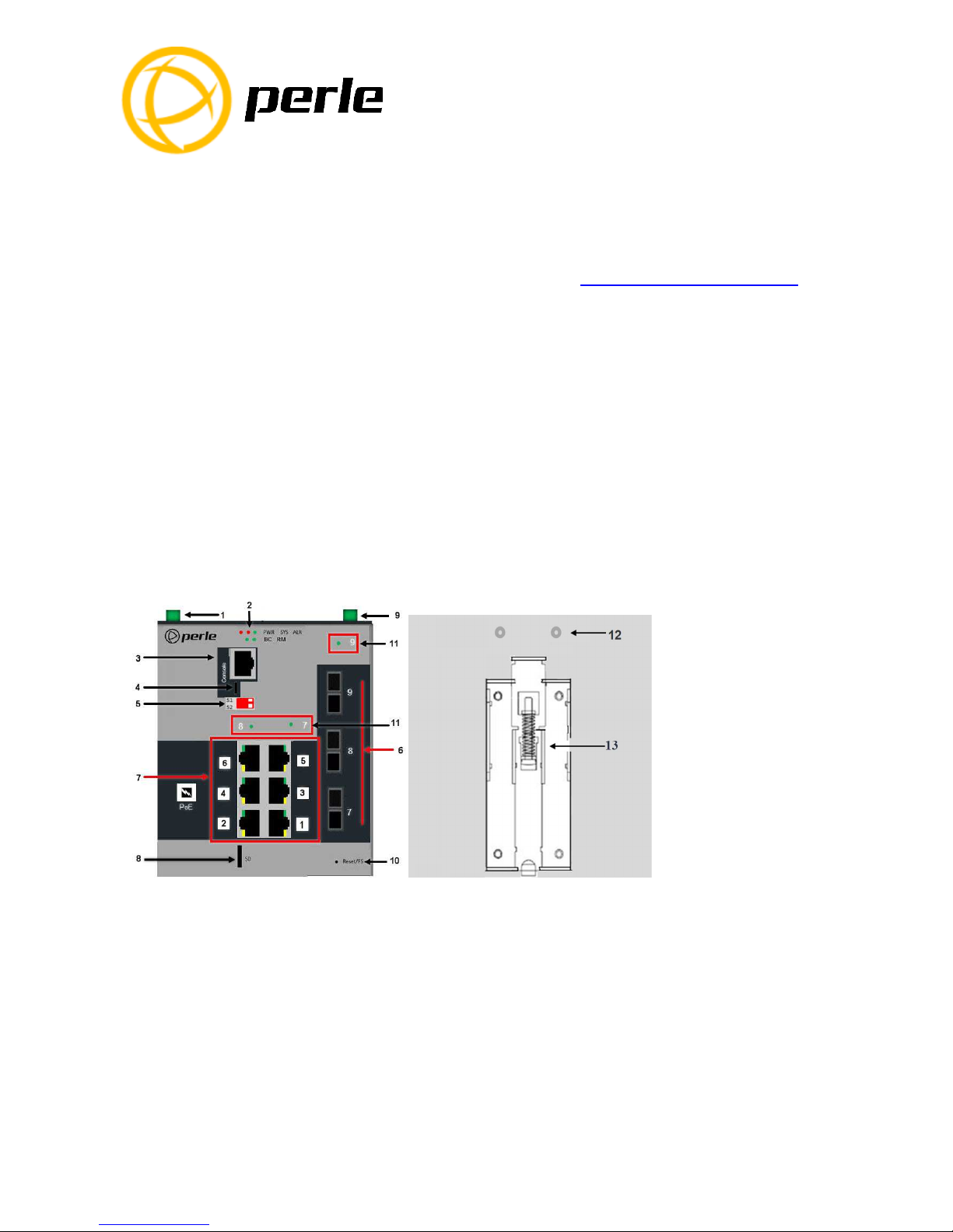
Front View Back View
1 –
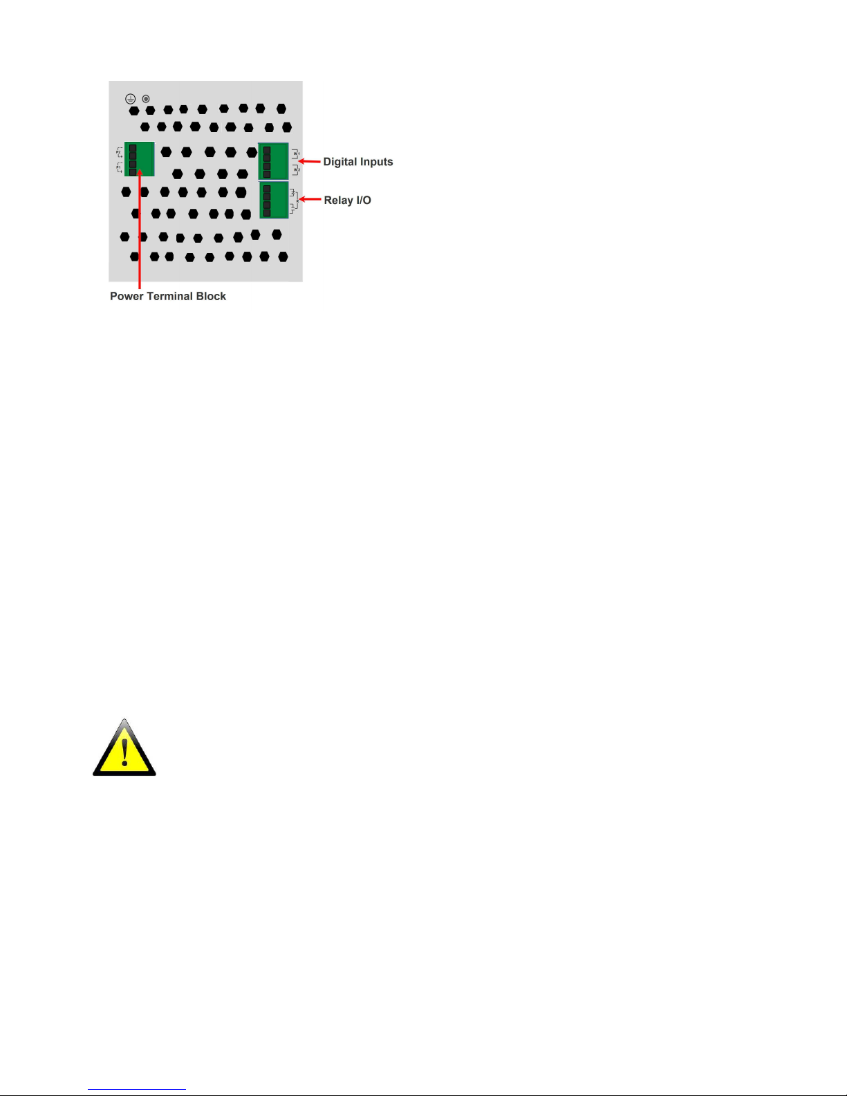
Terminal Block for Power 1, 2
7 –
PoE
/
PoE+ Enabled Ethernet Ports
2 – Status LEDs
8 –
SD Card Slot
3 – Console Port
–
serial
9 – Digit
al Inputs/Relay I/O
4 – Console Port
–
USB
10 –
Reset/FS(Fast Setup)
5 – DIP switches
11 – Fiber Status LEDs
6 –
1000Base
-
X SC/ST Fiber Ports
12 – Wall Mount Bracket Screw Holes
13 – DIN Rail Clip
Page 2
IDS-509GPP Switches Quick Start Guide
2
Wiring the Terminal Block
Connecting the switch to ground (optional)
If your installation requires additional grounding, refer to the Hardware Installation
Guide for information on connecting ground.
Connecting power to the IDS switch
You may connect both sets of power inputs to provide redundant power.
1. Ensure the power source is off prior to connection.
2. Using a pair of 12-16AWG wires, strip them both 7-8mm (5/16”).
3. Loosen the terminal block screws and connect positive (+) / negative (-) wires in
the +/- terminals.
4. Tighten terminal screws (0.51Nm torque). Ensure the wires are securely fastened.
5. Re-insert the terminal block connector if removed. Turn power on at source. Check
LED indicators for status.
6. Connect P2 (power source 2, beginning at Step 1.
For complete wiring instructions and for all Hazardous Locations and general safety warnings
consult the Hardware Installation Guide.
Connecting PoE/PoE+ devices
• Supports IEEE 802.3af (Type 1) and IEEE 802at-2009(Type 2) standards
• For PoE devices up to 15.4 watts per port
• For PoE+ devices up to 30 watts per port
Connecting Ethernet
Connect network or devices to Ethernet ports (1-9) using Cat5/5e Ethernet cables
Page 3

IDS-509GPP Switches Quick Start Guide
3
LED Indicators
(For detailed information refer to the Hardware Installation Guide)
PWR (Power Inputs)
• Green—P1 and P2 Power inputs are within specifications
• Orange—P1 or P2 not providing power within specifications
• Red—Neither P1 or P2 providing power within specifications
SYS (System status)
• Green blinking—System booting
• Green solid—System operating normally
• Green blinking fast—Fast Setup mode activated
• Red—Hardware fault or firmware load error.
Ethernet Port Link / Speed (Green and Yellow LEDs)
• 1000 Mbps Green on, Yellow off
• 100 Mbps Green on, Yellow on
• 10 Mbps Green off, Yellow on
Note: Flashing indicates activity
Note: Alr (Alarm), BC (Backup Coupling), RM (Ring Master) see
Hardware Installation Guide
Page 4
IDS-509GPP Switches Quick Start Guide
4
Fast Setup
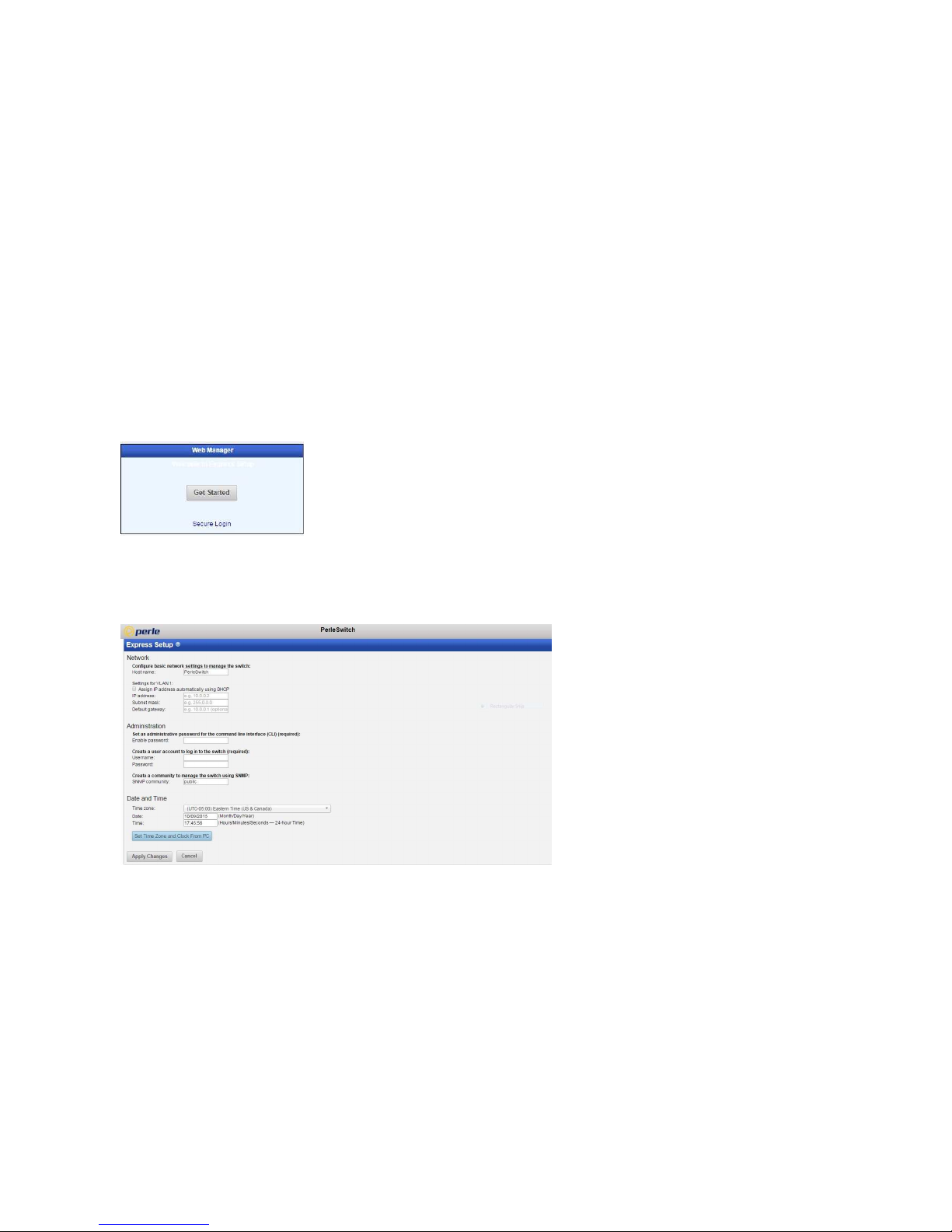
Fast Setup provides a simple method of doing an initial setup from a PC. It only
requires a PC Ethernet connection and a web browser. Other methods to configure the
IDS Switch can be found in the IDS Switch User’s guide.
1. Your PC must be set to obtain an IP address automatically using DHCP (See
Control Panel ->Network and Sharing Center -> Change adapter settings ->Local
Area Connection Properties ->Internet Protocol Version (TCP/IPv4) ->Properties >Select Obtain an IP address automatically.
2. Press and hold the reset button (9) on the switch for 4 seconds and then release it.
Since the reset button is recessed in the switch, a small tool such as a paper clip
will be required. The yellow and green LEDs on an unused RJ-45 connector will
flash rapidly to indicate where to plug in the Ethernet cable from your PC.
3. Using a web browser, enter to a well known webpage such as www.google.com,
you will be automatically directed to the IDS Get Started screen.
Note: While in Fast setup mode the IDS switch will use an IP address of 169.254.0.1. If step 3 fails to direct
the browser properly, then enter the switch’s IP address into the browser’s address bar
.
4. Once connected, fill in the required fields, apply changes to save and exit. The
configuration changes will be immediately applied to the switch.
5. The PC can now be reset to its normal network address and the switch can be
accessed using the conventional IP addressing.
© 2017 Perle Systems Limited. All rights reserved.
 Loading...