

Page 1

IDS-205F Hardware Installation Guide
Managed Industrial Ethernet Switches
www.perle.com
Updated: August 2016
Revision 1.00
Document Part#: 5500370-10
Page 2

THE SPECIFICATIONS AND INFORMATION REGARDING THE PRODUCTS IN THIS GUIDE ARE SUBJECT TO CHANGE
WITHOUT NOTICE. ALL STATEMENTS, INFORMATION, AND RECOMMENDATIONS IN THIS GUIDE ARE BELIEVED TO BE
ACCURATE BUT ARE PRESENTED WITHOUT WARRANTY OF ANY KIND, EXPRESS OR IMPLIED. USERS MUST TAKE
FULL RESPONSIBILITY FOR THEIR APPLICATION OF ANY PRODUCTS.
This equipment has been tested and found to comply with the limits for a Class A digital device, pursuant to part 15 of the FCC
rules. These limits are designed to provide reasonable protection against harmful interference when the equipment is operated in a
commercial environment. This equipment generates, uses, and can radiate radio-frequency energy and, if not installed and used in
accordance with this hardware guide may cause harmful interference to radio communications. Operation of this equipment in a
residential area is likely to cause harmful interference, in which case users will be required to correct the interference at their own
expense.
Modifications to this product not authorized by Perle could void the FCC approval and negate your authority to operate the product.
Perle reserves the right to make changes without further notice, to any products to improve reliability, function, or design.
Perle, the Perle logo, and IDS Switch are trademarks of Perle Systems Limited.
©2016. Perle Systems Limited.
IDS-205F Hardware Installation Guide
Page 3

Table of Contents
Preface . . . . . . . . . . . . . . . . . . . . . . . . . . . . . . . . . . . . . . . . . . . . . . . . . . . . . . . . . . . . . . . . . . . . . . . . . . . . . . . . . . . . . . . . . . . . . . . . . . . . . . . .2
Overview . . . . . . . . . . . . . . . . . . . . . . . . . . . . . . . . . . . . . . . . . . . . . . . . . . . . . . . . . . . . . . . . . . . . . . . . . . . . . . . . . . . . . . . . . . . . . . . . . . . . . .3
Switch Model View . . . . . . . . . . . . . . . . . . . . . . . . . . . . . . . . . . . . . . . . . . . . . . . . . . . . . . . . . . . . . . . . . . . . . . . . . . . . . . . . . . . . . . . . . . . .4
LED Indicators . . . . . . . . . . . . . . . . . . . . . . . . . . . . . . . . . . . . . . . . . . . . . . . . . . . . . . . . . . . . . . . . . . . . . . . . . . . . . . . . . . . . . . . . . . . . . . . . . 5
Ports . . . . . . . . . . . . . . . . . . . . . . . . . . . . . . . . . . . . . . . . . . . . . . . . . . . . . . . . . . . . . . . . . . . . . . . . . . . . . . . . . . . . . . . . . . . . . . . . . . . . . . . . . .6
Port Status Indicators . . . . . . . . . . . . . . . . . . . . . . . . . . . . . . . . . . . . . . . . . . . . . . . . . . . . . . . . . . . . . . . . . . . . . . . . . . . . . . . . . . . . . . . . . . 7
Installation . . . . . . . . . . . . . . . . . . . . . . . . . . . . . . . . . . . . . . . . . . . . . . . . . . . . . . . . . . . . . . . . . . . . . . . . . . . . . . . . . . . . . . . . . . . . . . . . . . . .8
Cautions and Warnings . . . . . . . . . . . . . . . . . . . . . . . . . . . . . . . . . . . . . . . . . . . . . . . . . . . . . . . . . . . . . . . . . . . . . . . . . . . . . . . . . . . .8
Terminal Block-Power Connectors . . . . . . . . . . . . . . . . . . . . . . . . . . . . . . . . . . . . . . . . . . . . . . . . . . . . . . . . . . . . . . . . . . . . . . . . . .9
Connecting the Console Port . . . . . . . . . . . . . . . . . . . . . . . . . . . . . . . . . . . . . . . . . . . . . . . . . . . . . . . . . . . . . . . . . . . . . . . . . . . . . .10
Connecting Destination Ports . . . . . . . . . . . . . . . . . . . . . . . . . . . . . . . . . . . . . . . . . . . . . . . . . . . . . . . . . . . . . . . . . . . . . . . . . . . . .11
Resetting the Switch . . . . . . . . . . . . . . . . . . . . . . . . . . . . . . . . . . . . . . . . . . . . . . . . . . . . . . . . . . . . . . . . . . . . . . . . . . . . . . . . . . . . . .12
Booting the Switch . . . . . . . . . . . . . . . . . . . . . . . . . . . . . . . . . . . . . . . . . . . . . . . . . . . . . . . . . . . . . . . . . . . . . . . . . . . . . . . . . . . . . . .13
Fast Setup Mode . . . . . . . . . . . . . . . . . . . . . . . . . . . . . . . . . . . . . . . . . . . . . . . . . . . . . . . . . . . . . . . . . . . . . . . . . . . . . . . . . . . . . . . . . .13
Password Recovery . . . . . . . . . . . . . . . . . . . . . . . . . . . . . . . . . . . . . . . . . . . . . . . . . . . . . . . . . . . . . . . . . . . . . . . . . . . . . . . . . . . . . . .13
Configuring the IDS Switch . . . . . . . . . . . . . . . . . . . . . . . . . . . . . . . . . . . . . . . . . . . . . . . . . . . . . . . . . . . . . . . . . . . . . . . . . . . . . . . .14
Appendix A - Technical Specifications . . . . . . . . . . . . . . . . . . . . . . . . . . . . . . . . . . . . . . . . . . . . . . . . . . . . . . . . . . . . . . . . . . . . . . . . .15
Appendix B - Labels . . . . . . . . . . . . . . . . . . . . . . . . . . . . . . . . . . . . . . . . . . . . . . . . . . . . . . . . . . . . . . . . . . . . . . . . . . . . . . . . . . . . . . . . . .17
Appendix C - Mechanical Drawings . . . . . . . . . . . . . . . . . . . . . . . . . . . . . . . . . . . . . . . . . . . . . . . . . . . . . . . . . . . . . . . . . . . . . . . . . . .18
Appendix D - IDS DIN Rail and Wall Mounting . . . . . . . . . . . . . . . . . . . . . . . . . . . . . . . . . . . . . . . . . . . . . . . . . . . . . . . . . . . . . . . . .19
Appendix E - IDS Maintenance . . . . . . . . . . . . . . . . . . . . . . . . . . . . . . . . . . . . . . . . . . . . . . . . . . . . . . . . . . . . . . . . . . . . . . . . . . . . . . . .21
Appendix F - Cables and Connectors . . . . . . . . . . . . . . . . . . . . . . . . . . . . . . . . . . . . . . . . . . . . . . . . . . . . . . . . . . . . . . . . . . . . . . . . . .22
Page 4

Preface
Audience
This guide is for the network or computer technician responsible for installing Perle IDS-205 series
switches. We assume that you are familiar with the concepts and terminology of Ethernet and local area
networks.
Purpose
This document describes the hardware and physical characteristics of the Perle IDS switch. It covers
hardware features as well as installation and operation of the switch. This document does not cover how
to configure your Perle IDS switch. Information to configure your Perle IDS switch can be found in the
Perle IDS User’s Guide
Package Contents
• IDS switch with attached DIN rail mounting bracket
• Quick Start Guide
Document Conventions
This document contains the following conventions:
Most text is presented in the typeface used in this paragraph. Other typefaces are used to help you
identify certain types of information. The other typefaces are:
2
Note: Means reader take note: notes contain helpful suggestions.
Caution: Means reader be careful. In this situation, you might perform an action that could result in
equipment damage or loss of data.
Warning: IMPORTANT SAFETY INSTRUCTIONS
Means danger. You are in a situation that could cause bodily injury. Before you work on any equipment,
be aware of the hazards involved with electrical circuitry and be familiar with standard practices for
preventing accidents. Only qualified personnel should connect power to this unit.
IDS-205F Hardware Installation Guide
Page 5
Overview
This chapter discusses the following topics:
• LED Indicators
• Switch Model View
•Ports
• Port Status Indicators
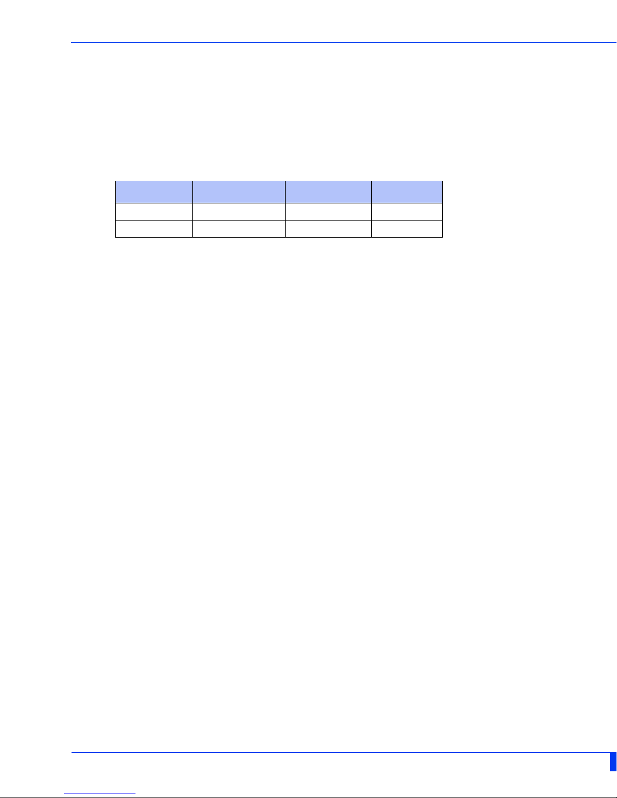
The table below gives a brief overview of the models covered in this guide. For more details and for the
most up-to-date list of models, please refer to the product pages at www.perle.com.
Standard Models Port 1-4 Port 5 Temp
IDS-205F-XXXXXX 10/100/1000Base-T (RJ45) 100Base-X SC/ST fiber Standard
IDS-205F-XXXXXX-XT 10/100/1000Base-T (RJ45) 100Base-X SC/ST fiber Industrial
Note: xxxxxx denotes the specific type of fiber port installed. Refer to the Perle Website for up to date
details on the available options.
3
IDS-205F Hardware Installation Guide
Page 6
Switch Model View
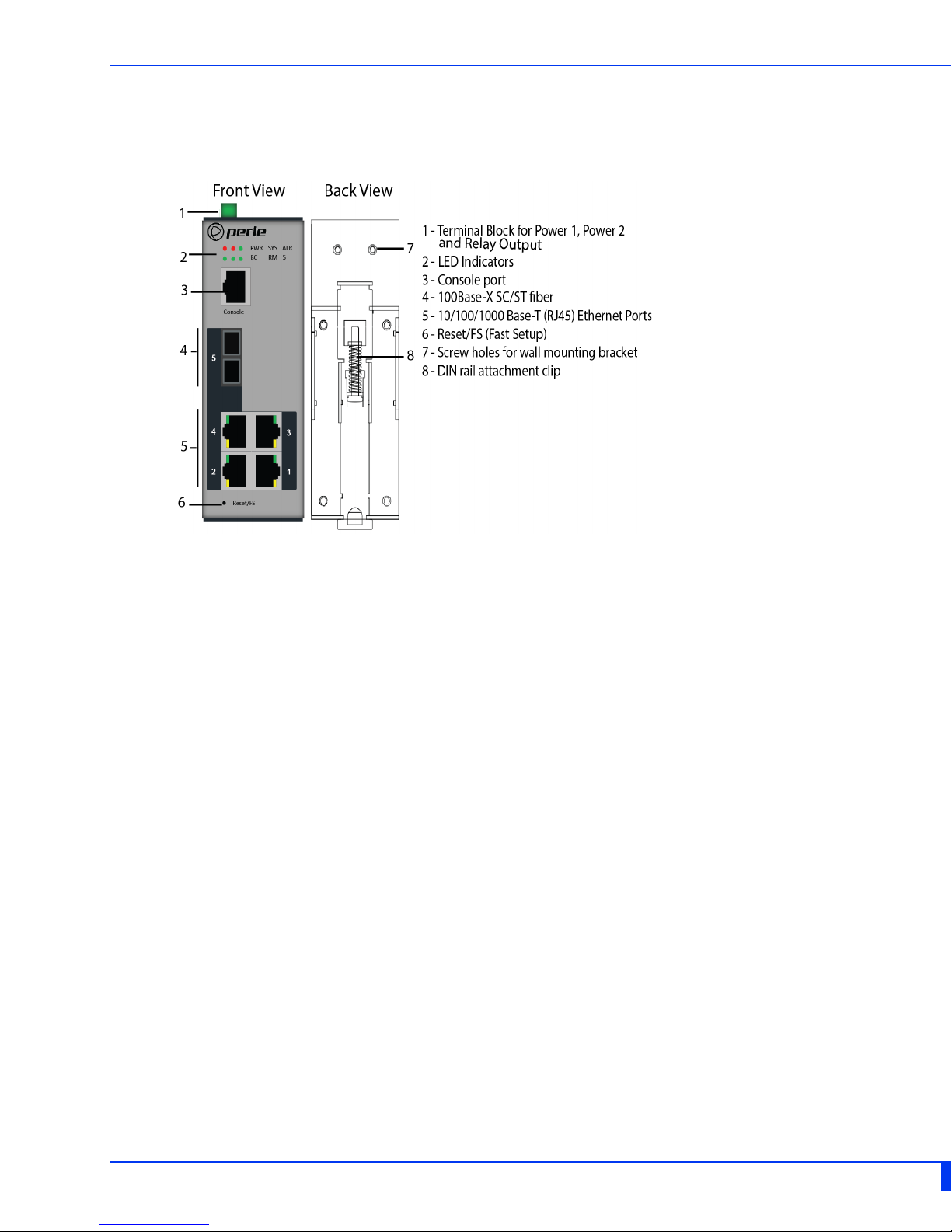
IDS-205F
4
Note: Fiber Port may appear different, depending on the type of fiber port installed.
IDS-205F Hardware Installation Guide
Page 7
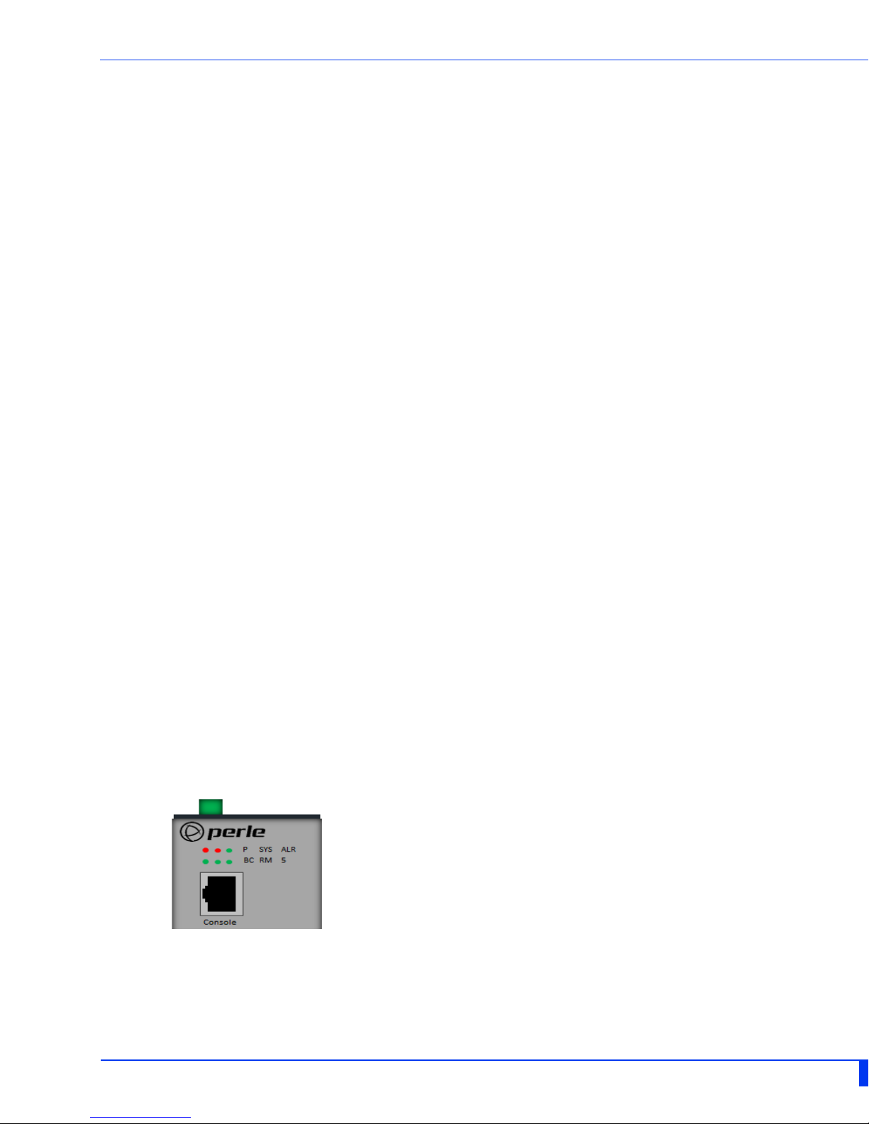
LED Indicators
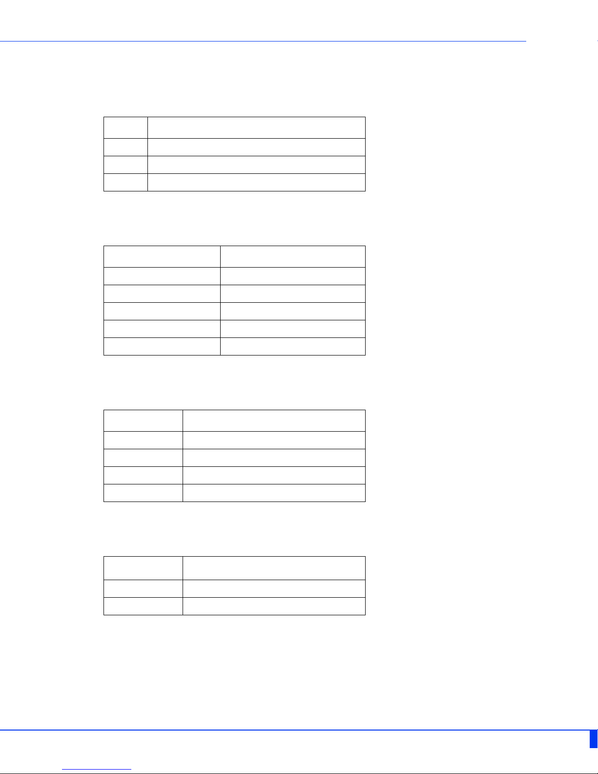
P (Power Inputs)
State Description
Green P1 and P2 Power inputs within specifications
Yellow P1 or P2 Providing power within specifications
Red
Sys (System Status)
State Description
Green - blinking (after power on) System booting
Green - solid System ready/operating normally
Green - blinking slowly Fast Setup Mode activated/port available
Green - blinking fast Fast Setup Mode activated/no port available
Red
Alr (Alarm)
State Description
Off No alarms configured
Green - solid Alarms configured, but no alarms detected
Neither P1 or P2 providing power within specifications
Hardware fault or firmware load error
Red - solid
Red - blinking
BC (Backup Coupling)
State Description
Off Backup Coupling not enabled
Green - solid Backup Coupling Link enabled
Alarm condition detected
Alarm condition detected and Alarm Relay activated
IDS-205F Hardware Installation Guide
Page 8
RM (Ring Master)
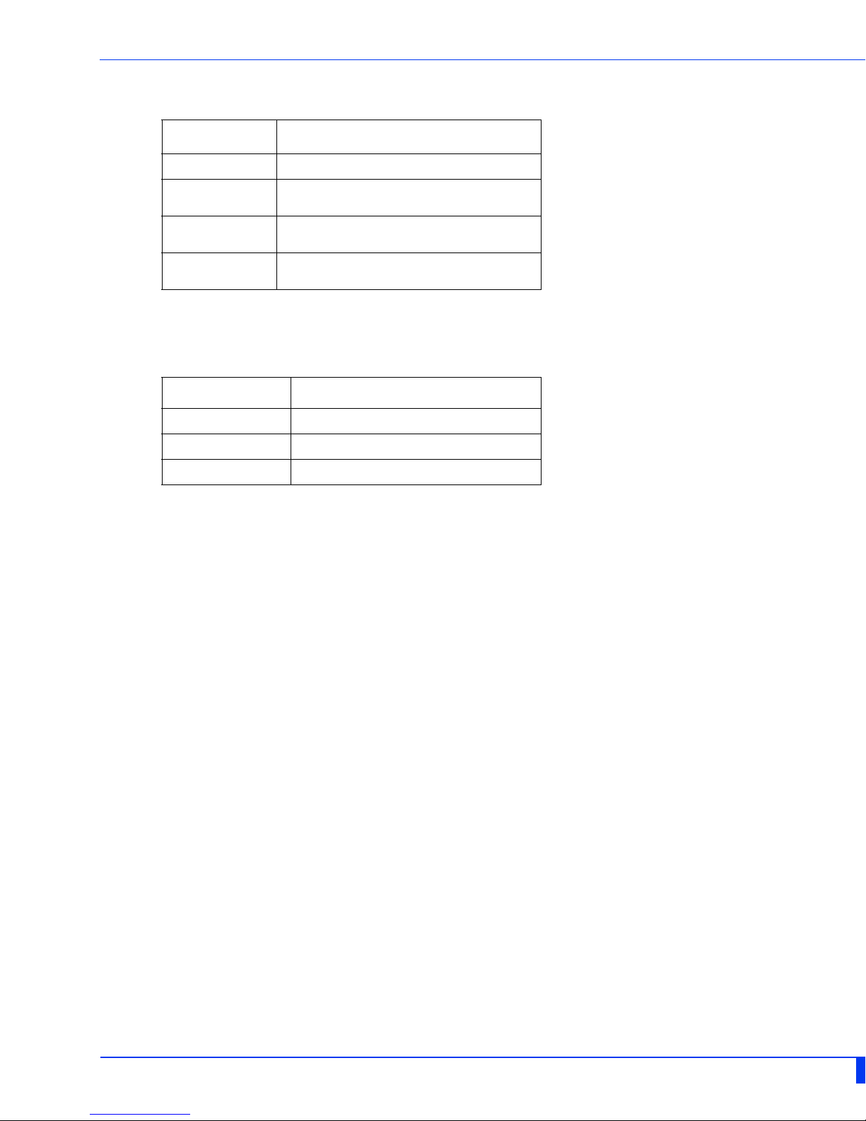
State Description
Off Ring Master not activated
LED Indicators 6
Green - solid Ring Master Active, redundant port blocked. Coupling Link
Green - flashing Ring Master unable to establish a ring due to missing link on
Yellow - solid Ring Master Active, redundant port unblocked - indicates a
enabled
one of the Ring ports
break in the Ring
5 (Port 5 - Fiberport Link/Activity)
State Description
Off Link Down
Green - blinking Link and activity
Green - blinking slowly Port in error disable or suspended state
IDS-205F Hardware Installation Guide
Page 9

Ports
10/100/1000Base-T Ports
These ports provide the standard gigabit Ethernet interface. They provide speeds of 10/100 or
1000 Mb/s through twisted pair (UTP) cables of up to 100 meters (328ft) in length.
RJ-45 Console Port
This is a console management port which will provide access to the switch management function using
our industry standard CLI command set. This port has an RJ-45 connector. See RJ-45-Console Port Pinouts for pinouts.
100Base-X SC/ST Fiber Ports
These ports provide a built in fiber module that provides fiber connectivity at 100 Mb/s. These fiber
ports are available on the switches in a variety of distances, wavelengths and connector types. Consult
the full model list at www.perle.com.
Power Connector
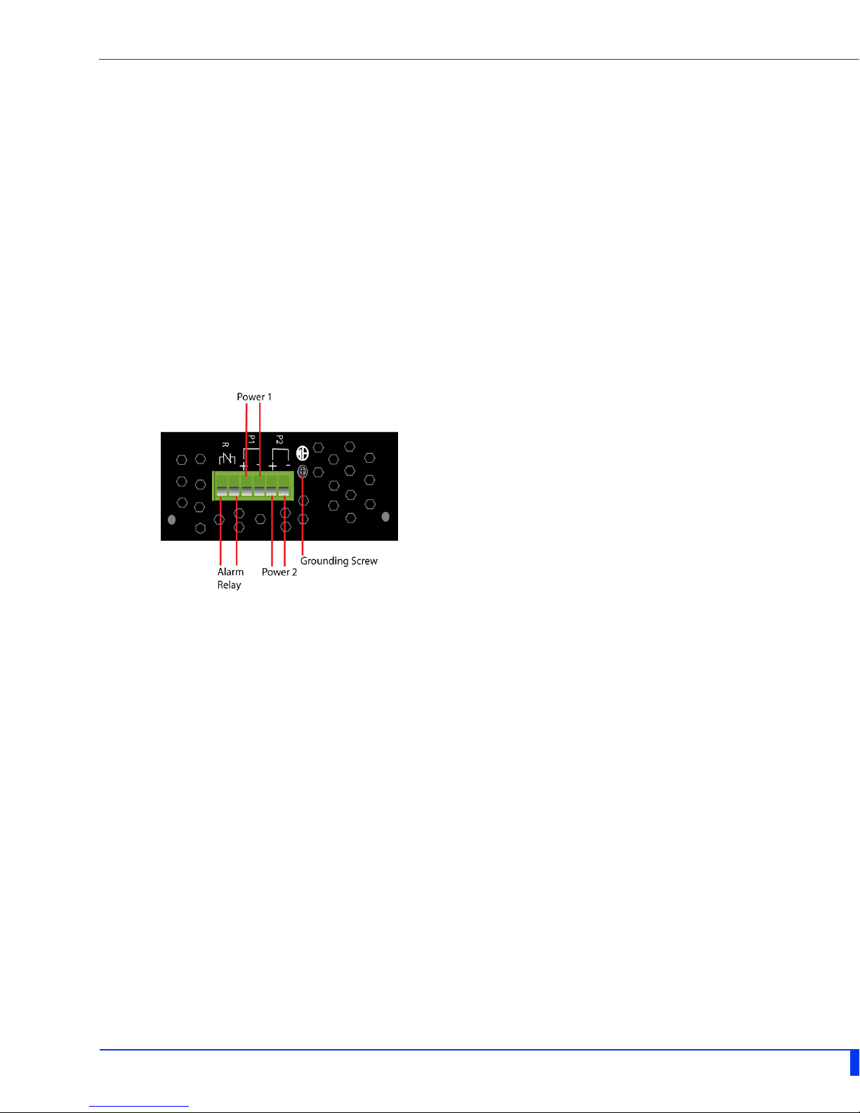
The power input connector has provisions for dual inputs. Two independent power sources can be used
to power the switch. If one power input fails, the other power input will power the switch.
7
Alarm Relay Connector
The Alarm Relay can be energized by the software or hardware under certain conditions. It can then be
used to trigger an external alarm circuit such as a light or sounding device. This connector provides a
Normally Closed (NC) dry contact on the connector block.
IDS-205F Hardware Installation Guide
Page 10
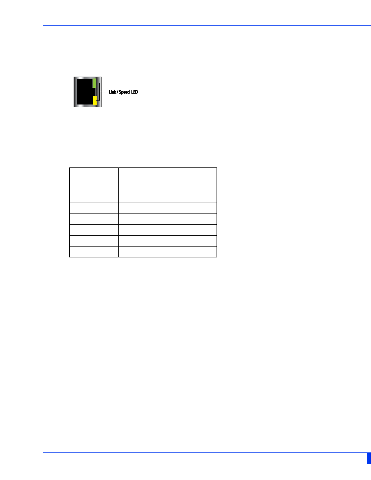
Port Status Indicators
Ethernet Port Status Indicators
Port Link / Speed (Green and Yellow LEDs)
State Description
Green 1000 Mbps
8
Green / Yellow 100 Mbps
Yellow 10 Mbps
On solid Port Link
Random blinking Port Link and Activity
Slow blinking Error disabled
Rapid blinking Port in Fast Setup Mode
IDS-205F Hardware Installation Guide
Page 11

Installation
This chapter discusses the following topics:
• Cautions and Warnings
• Terminal Block-Power Connectors
• Grounding the IDS Switch
•Connecting Power to the IDS Switch
• Wiring the Relay Alarm
•Connecting the Console Port
•RJ45 Console Port
• Resetting the Password
• Connecting Destination Ports
• Configuring the IDS Switch
Cautions and Warnings
General Cautions and Warnings
Warning: Power sources must be off prior to beginning the power connection steps. Read the installa-
tion instructions before you connect the unit to its power source.
Warning: Ensure that the voltage and current ratings of the intended power source are appropriate for
the IDS switch as indicated on the product label.
Warning: Ensure that the installation and electrical wiring of the equipment is performed by trained
and qualified personnel and that the installation complies with all local and national electrical codes.
Warning: This unit should be installed in a restricted access location where access can only be gained
by service personnel or users who have been instructed about the reasons for the restrictions applied to
the location and about any precautions that shall be taken; and access is through the use of a tool or
lock and key, or any means of security, and is controlled by the authority responsible for the location.
Warning: If the unit is installed vertically in a living or office environment, the device must be operated
exclusively in switch cabinets with fire protection characteristics in accordance with EN-60950-1
Warning: The working voltage inputs are designed for operation with Safety extra low Voltage (SELV).
Connect only to SELV circuits with voltage restrictions in line with IEC/EN 60950-1.
Hazardous Location Warnings
Warning: This equipment shall be installed in an enclosure that provides a degree of protection not less
then IP54 in accordance with EN-60079-15 and accessible only by the use of a tool.
Warning: The equipment shall only be used in an area of not more than pollution degree 2, as defined
in IEC 60664-1.
Warning: These devices are open-type devices that are to be installed in an enclosure with tool remov-
able cover or door, suitable for the environment.
Warning: This equipment is suitable for use in Class 1, Division 2, Groups A, B, C, D, or only non hazard-
ous locations.
Warning: WARNING-EXPLOSION HAZARD - Do not disconnect equipment unless power has been
removed or the area is known to be non-hazardous.
Warning: WARNING-EXPLOSION HAZARD - Substitution of any components on this switch may impair
suitability for Class 1, Division 2.
Warning: Transient protection shall be provided that is set at a level not exceeding 140% of the peak
rated voltage value at the supply terminals to the equipment.
Warning: Ensure power has been removed at the source of the alarm circuit prior to proceeding with
the connections to the alarm relay.
Warning: Ensure that voltage and current supplied by the alarm circuits are within the stated Alarm
Relay specifications.
IDS-205F Hardware Installation Guide
Page 12
Warning: In hazardous location installations, failure to remove from the source prior to completing the
wiring connections to the alarm relay could cause an electrical arc resulting in a possible explosion.
Warning: Power supply of the equipment must be rated appropriately (see Appendix for specifications)
with limited power. Limited power means complying with one of the following requirements.
Class 2 circuit according to Canadian Electrical Code, Part 1, C22.1
Class 2 circuit according to National Electrical Code, NFPA-70
Limited Power Supply (LPS) according to EN/IEC 60950-1;
Limited-energy circuit according to EN/IEC 61010-1
Warning: If this equipment is used in a manner not specified by the manufacturer, the protection pro-
vided by the equipment may be impaired.
Warning: In case of malfunction or damage, no attempts at repair should be made. Do not dismantle
the product. All repairs need to be made by a qualified Perle representative.
Warning: Explosion hazard. Do not remove or replace lamps, fuses or plug-in modules (as applicable)
unless power has been disconnected or the area is free of ignitable concentrations.
Warning: Explosion hazard. Do not disconnect while the circuit is live or unless the area is free of ignit-
able concentrations.
Terminal Block-Power Connectors
Installation 10
Grounding the IDS Switch
Caution: Minimum temperature rating of the cable to be connected to the field wiring terminals is
105° C.
If your installation requires additional grounding, follow this procedure.
Grounding the chassis requires the following items:
• One grounding lug (not provided)
• One 12 AWG (3.31 mm²) wire (not provided)
1 Attach the ground wire to the grounding lug; follow the instructions from the ground lug
manufacturer.
2 Attach the grounding lug to the chassis and secure with the grounding screw provided.
IDS-205F Hardware Installation Guide
Page 13
Connecting Power to the IDS Switch
The IDS switch has two power inputs that can be connected simultaneously to provide redundant
power. If one power source fails the other source acts as a backup, and automatically powers the switch.
Conductors suitable for use in an ambient temperature of 98
minals.
1 Ensure the power source is off prior to connection.
2 Strip 2x12-20AWG (3.31 mm² - 0.52 mm²) twisted pair copper wires 7-8 mm.
3 Loosen the terminal block screws and connect positive (+) / negative (-) wires into the +/-
terminals.
4 Tighten terminal screws (0.5Nm torque). Ensure the wires are securely fastened.
5 Re-insert the Terminal Block connector if removed. Turn on power source. Check LED indicators in
the guide for power status.
6 Connect P2 (power source 2, beginning at Step 1).
7 Ensure that there is one individual conductor for each clamping point.
Wiring the Relay Alarm
The IDS switch has a Normally Closed (NC) relay with terminals located on the top panel of the unit. The
IDS switch can be connected to an external powered device such as a siren or light for visual or audible
notification of an alarm status.
1 Ensure the power source is off prior to connection.
2 Strip 2x12-20AWG (3.31 mm² -0.52 mm²) twisted pair copper wires 7-8 mm.
3 Loosen the terminal block screws and connect wires into the terminals.
4 Tighten terminal screws. Ensure the wires are securely fastened.
5 Re-insert the Terminal block connector if removed.
6 Turn on power source.
Installation 11
o
C must be used for the Power Supply Ter-
Connecting the Console Port
The IDS switch can be fully configured and managed from the console port. The console port provides
direct access to the Command Line Interface (CLI). See Console Port and RJ45-Console Port Pinouts for
proper console port pinouts.
RJ45 Console Port
The console port uses a shielded cable with an 8-pin female connector (with DTE pinouts).
Front View
1 Connect an RJ45 cable to the IDS switch console port (RJ45) and the other end of the cable to a
COM port on your PC.
2 Choose Start > Control Panel > Systems or equivalent on the Windows Operating System you are
using.
IDS-205F Hardware Installation Guide
Page 14

Installation 12
3 Click the Hardware tab and choose Device Manager, Expand the Ports(COM & LPT) section. This will
expand the drop down to show the number of com ports on your system. Connect the cable to one
of these ports (probably com1 or com2).
4 Start an terminal-emulation program (such as Putty or SecureCRT) on the COM port where you have
connected the cable PC.
5 Configure this COM port within the terminal emulation program with the following parameters:
•9600 baud
•8 data bits
•1 stop bit
•No parity
•None (flow control)
6 Connect power to the switch as described in Connecting Power to the IDS Switch.
7 The PC will display the bootloader sequence.
8 When the booting (see Booting, Resetting the Switch) of the IDS is completed, press Enter to
display the setup prompt.
War ning : If you connect or disconnect the console cable with the power applied to the switch or any
device on the network, an electrical arc can occur. This could cause an explosion when installed in a hazardous location. Ensure the power is removed from all devices prior to making the cable connection.
Connecting Destination Ports
Data Port Connections
By default all of the 10/100/1000 ports will automatically set themselves up to match the speeds of all
attached devices. If auto negotiation is not supported by one or more attached devices, the ports can
be configured to operate at fixed speeds and duplex settings.
Warning: In hazardous location installations, failure to remove the power from the source prior when
completing the wiring connections to the Ethernet ports could cause an electrical arc resulting in a possible explosion.
To connect to 10Base-T, 100Base-TX or 1000Base-T follow these steps:
1 When connecting to devices, workstations, servers or routers connect a straight through Ethernet
cable to a 10/100/1000 RJ45 connector on the front of the IDS switch. Gigabit Ethernet requires
CAT5 or better.
2 Once the device is connected and link is established the link LEDs will turn on. These LEDs will
indicate whether you have a 10,100 or 1000 Mb/s link to the switch. See. (LED Indicators) for more
details.
Note: It may take a few seconds for the device to become active. By default the IDS switch will have
Rapid Spanning Tree (RSTP) protocol enabled. This protocol will first check the network for any cabling
loops prior to bringing the port up, in order to prevent network disruptions.
To connect to the 100Base-X Fiber devices:
1 Connect a fiber with the appropriate connector and fiber type for the specific IDS model. Ensure
that the device being connected to matches the fiber characteristics of the switch.
2 Once the fiber is connected and a link is established the LED (5) will display link and activity.
IDS-205F Hardware Installation Guide
Page 15
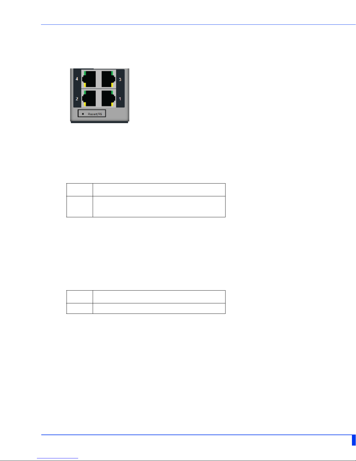
Resetting the Switch
The Reset/Fast Setup button is located near the bottom of the switch. A small tool such as a paper clip is
needed to access the recessed button.
Soft Reset
To reset/restart the switch you can perform a soft reset. Press and immediately release the reset button
to perform a soft reset.
Installation 13
LED Behavior
PWR The PWR LED will remain solid yellow during the boot process. Once the
system software has been loaded the PWR LED will reflect the status of
the power inputs.
Hard Reset
Hard Reset performs a power-off for the switch without requiring a disconnection of power. Once
powered off, the switch can be powered back on by pressing the reset switch again or by disconnecting
power at source and re-applying. Press and hold the reset button for at least 8 seconds. The switch will
perform a complete power down and stay in the powered off state. Press the reset button to power the
switch on.
LED Behavior
ALL All LEDs will be off after 8 seconds.
Reset to Factory Default Configuration
The IDS-205F can be reset to the Factory default configuration. When this is done, all configuration,
user IDs, passwords and security certificates are deleted. The start-up and backup software are unaffected. Follow this procedure:
• Power off the switch
• Press and hold the reset button
• While continuing to hold the reset button, apply power to the switch
• ALR LED will go on after power up; when it goes out; release the reset button
The switch is now reset to factory default configuration.
IDS-205F Hardware Installation Guide
Page 16
Booting the Switch
When first applying power to the IDS switch, it will startup and go through the boot process. The LEDs
will behave according to the table below.
LED Behavior
Installation 14
PWR Yellow during the booting process. Once the system software has been
SYS Green blinking - Boot process underway.
loaded, the PWR LED will reflect the status of the power inputs.
Fast Setup Mode
This mode allows you to perform initial configuration of the switch using your Web browser. Fast Setup
Mode can be activated when the switch is in Factory Default Mode. This mode assigns an IP address to
the switch and to a connected PC to permit configuration. Your switch will be shipped to you in Factory
default mode. See the Quick Start Guide that came with your IDS switch on how to connect to your
switch for the first time.
LED Behavior
PWR
Port Link / Speed Rapid blinking on the first available RJ-45 port to which the PC can be
Press and hold the Reset/FS button. Release button when LED changes from
Red to Yellow.
connected.
Password Recovery
When the switch is not in factory default the "Fast Setup Mode" sequence will activate Password
recovery.
Note: The password recovery feature can be disabled in the software.
LED Behavior
ALR
On solid - during reset process
Off - to indicate that reset has completed
IDS-205F Hardware Installation Guide
Page 17

Configuring the IDS Switch
The IDS switch can be configured, operated and monitored using any of the following methods. See the
IDS User’s Guide for more details.
CLI
A familiar text-based Command Line Interface that is based on accepted industry standard syntax and
structure. The CLI can be accessed from the console port. Once a valid IP address is configured on the
switch, Telnet or SSH can also be used to access the switch for administration purposes. See the IDS
Command Line Reference Guide for more information.
Web Device Manager
The Perle Web Device Manager is an embedded Web based application that provides an easy to use
browser interface for managing the switch. This interface provides the ability to configure and manage
the switch. This is accessible through any standard desktop web browser. Requires switch to have a valid
IP address.
Fast Setup
Installation 15
SNMP
This utility provides the ability to do either an initial setup (out of the box) or a recovery setup. In order
to use this utility a PC must be connected to one of the switches data ports and the function is activated using
the reset button on the front panel.
The switch can be managed with an SNMP compatible management station that is running platforms
such as HP Openview or Perle’s PerleVIEW NMS.
IDS-205F Hardware Installation Guide
Page 18
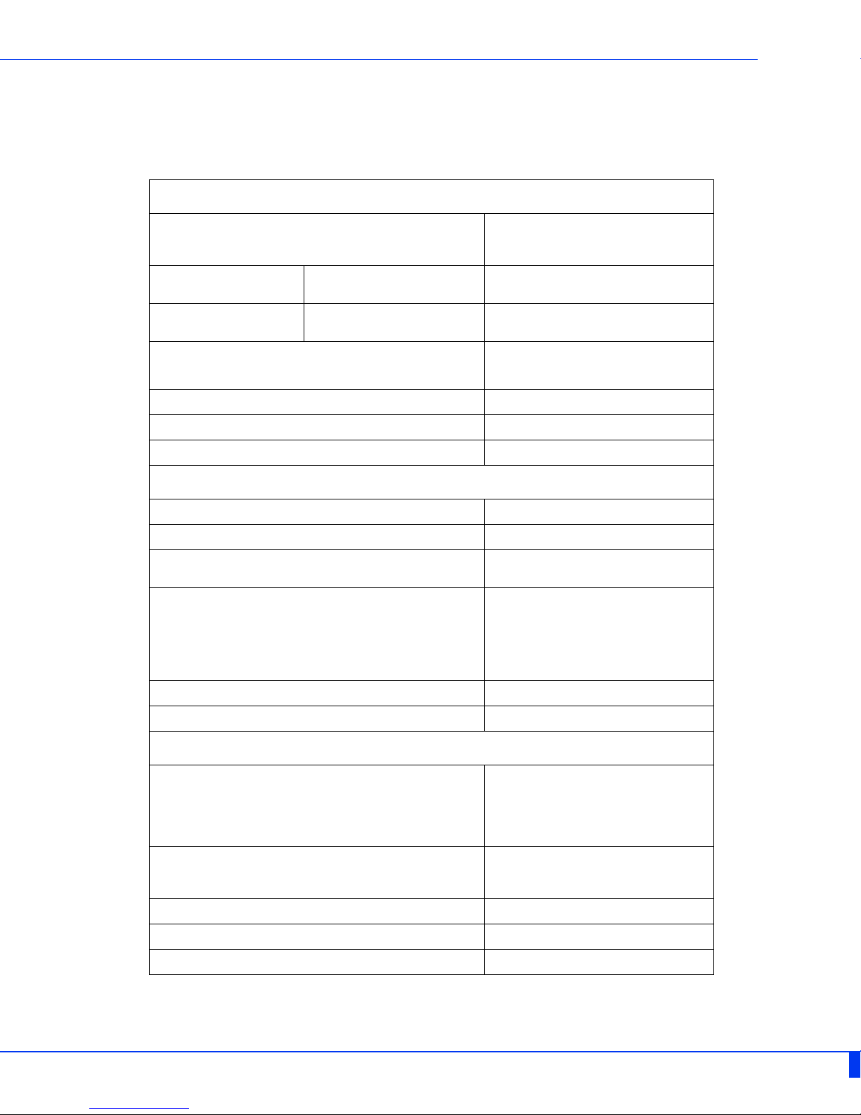
Appendix A - Technical Specifications
This appendix provides the technical specification for the IDS-205F(-XT) switches.
Specifications
Dual input terminal block 9.6 to 60 VDC
Models Rated Voltage Max. Rated
IDS - 205F(-XT) 9.6 Vdc 0.350A
Rated Cable Temperatures
IDS-205F
IDS-205F(-XT)
Overload Current Protection Fuse
Reverse Polarity Protection Yes
Weight 610 grams
(CLASS 2) Current
SELV, limited-energy per 61010-1 cl.9.4
Alarm Relay Output
1.0A at 24Vdc
0.5A at 48Vdc
>74°C
>90°C
Interfaces
10/100/1000Base-T (RJ45) Industry standard RJ-45 connector
Fiber 100Base-X Fixed Fiber (SC/ST) - varies by model
Console RJ-45 connector
LED Indicators PWR - Power Inputs
SYS - System Status
ALR - Alarm
BC - For Future Use
RM - For Future Use
5 - Fiber Port Link/Activity
Ports 1-4 G/Y - Link/Activity/Speed
Reset/FS (Fast Setup) switch Inset on front panel
Terminal Block Rated at 105°C (221°F)
Environmental
Operating Temperature
Commercial Models (IDS-205F)
Industrial Models (IDS-205F-XT)
Storage Temperature
Commercial Models (IDS-205F)
Industrial Models (IDS-205F-XT)
Operating Humidity 5% to 90% non-condensing
Storage Humidity 5% to 95% non-condensing
Operating Altitude Up to 3,048 m (10,000 ft)
IDS-205F Hardware Installation Guide
-10°C to 60°C (14°F to 140°F)
-10°C ≤ TAMB ≤ to 60°C
-40°C to 75°C (-40°F to 167°F)
-40°C ≤ TAMB ≤ 75°C
-25°C to 75°C (-13°F to 167°F)
-40°C C to 85°C (-40°F to 185°F)
Page 19

Appendix A - Technical Specifications 17
IP Ingress Protection IP20
Regulatory Approvals
Standard Safety cUL 60950-1, EN 60950, EN/IEC 60950
Industrial Safety UL 61010-1, UL 61010-2-201
EMI/EMC FCC 47 Part 15 - Class A
Standard emissions FCC 47 Part 15 Class A CISPR
Hazloc (Hazardous locations) ANSI/ISA 12.12.01 Class1 Division 2
Minimum EMC and Immunity EN/IEC 61000-4-2(ESD); Contact
Laser Safety EN 60825-1:2007 FDA/CDRH 21
IEEE Compliance 802.3-10BaseT
EN 61010-1, EN 61010-2-201
CISPR22:2008 / EN55022:2010 Class A CISPR
24:2010/EN55024:2010
22:2008/EN55022:2010(Class A)
CISPR 24:2010EN 55024:2010
Groups A-D A TEX Class 1 Zone 2
discharge +/- 6kV
Air Discharge +/- 8kV
EN/IEC 61000-4-4(EFT);
DC power line, +/- 2kV,
Data line +/- 4kV
EN/IEC 61000-4-5(SURGE);
DC power line Line/Line +/- 4kV,
Line/Earth +/- 2kV,
Data line/earth +/- 2kV
EN/IEC 61000-4-6 (CS);
150kHz to 80 MHz: 10V
EN/IEC 61000-4-8 (Magnetic Field)
EN/IEC 61000-6-2 (General Immunity)
CFR1040.10/CFR1040.11
802.3u-100Base-TX
100BaseFX
802.3x-Flow Control
802.3z-1000BaseLX
802.3ab-1000BaseTX
Note: The safety certifications apply only to ambient temperatures under 60°C (140°F). However, the IDS
switch can function in the environmental conditions listed above.
Contacting Technical Support
Contact information for the Perle Technical Assistance Center (PTAC) can be found at the link below.
A Technical Support Query may be made via this webpage.
www.perle.com/support_services/support_request.shtml
Warranty / Registration
This product is covered by the Perle Ethernet Switches Warranty. Details can be found at:
https://www.perle.com/support_services/warranty.shtml
IDS-205F Hardware Installation Guide
Page 20
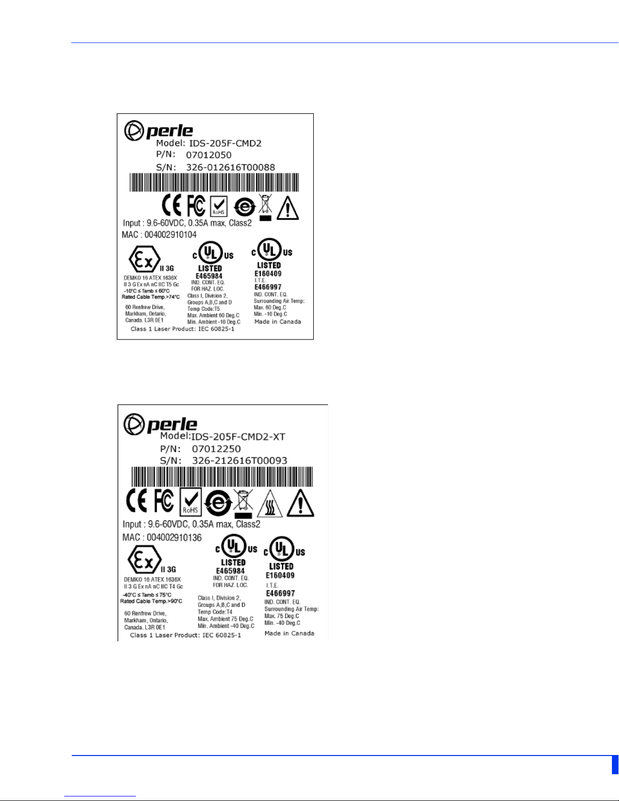
Appendix B - Labels
IDS-205F
18
IDS-205F-XT
IDS-205F Hardware Installation Guide
Page 21
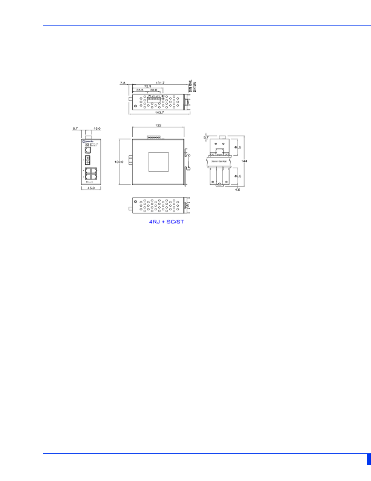
Appendix C - Mechanical Drawings
5-port RJ-45
19
IDS-205F Hardware Installation Guide
Page 22
Appendix D - IDS DIN Rail and Wall Mounting
This appendix provides instruction on the following:
• Mounting the IDS Switch on a DIN Rail
• Removing the IDS from the DIN Rail
• Wall Mounting the IDS
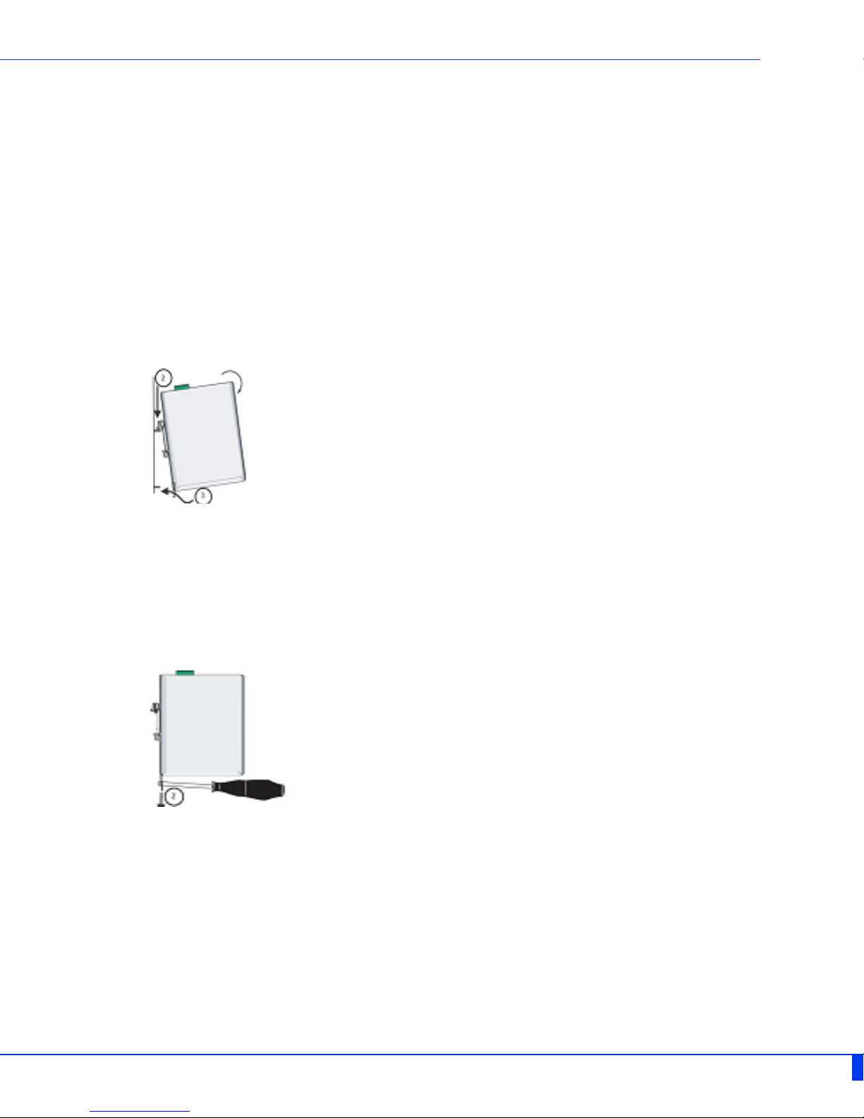
Mounting the IDS Switch on a DIN Rail
1 The DIN rail clip will be fixed to the back of the IDS unit when you receive the switch.
2 Position the IDS switch such that the top hooks of the DIN rail clip attach onto the top of the DIN
rail.
3 Rotate the bottom of the IDS switch towards the rail. This will snap the bottom hooks of the DIN
rail clip onto the bottom of the DIN rail.
See diagram below
Removing the IDS from the DIN Rail
1 The DIN rail attachment clip has a slot at the bottom of the latch that is visible beneath the switch
when it is mounted.
2 Insert a flat blade screwdriver into the slot and twist the base to release the clip. Alternatively a
downward force on the clip will release the clip.
3 When the clip is released, pull the bottom of the switch out slightly and remove the switch from the DIN rail.
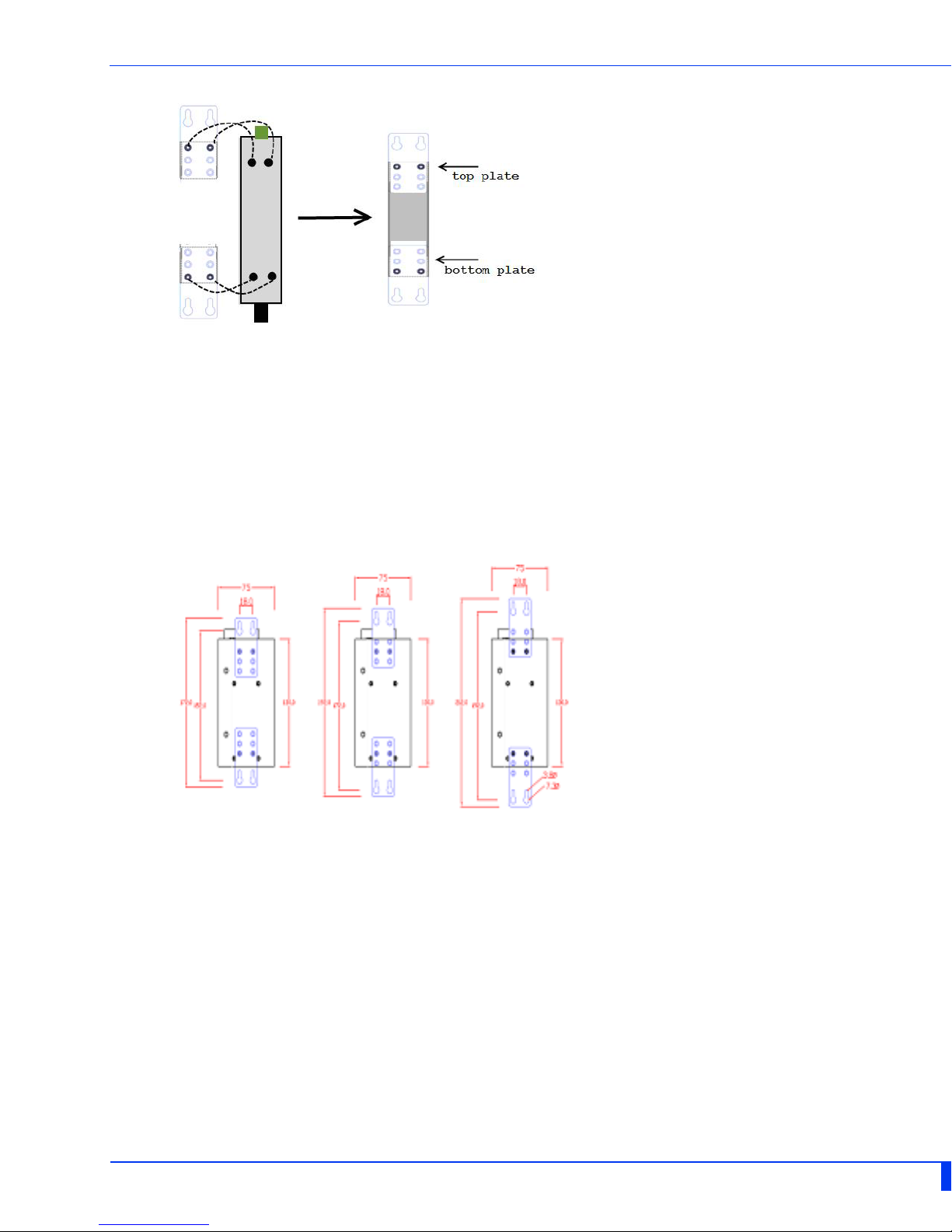
Wall Mounting the IDS
If you have purchased the optional wall mounting kit then proceed as below:
1 Remove the DIN rail clip from the rear panel on the IDS switch.
2 Attach the wall mount plates to the IDS switch as shown below using the screws provided in the kit.
IDS-205F Hardware Installation Guide
Page 23
Appendix D - IDS DIN Rail and Wall Mounting 21
3 Use the wall mount plates as a guide to mark the spot where the screws will be placed.
4 Drive the screws into the wall leaving about 2 mm of the screw protruding from the wall to allow
room for sliding the wall mount panel between the wall and the screws.
5 Once the screws are fixed to the wall, insert the four screw heads through the large parts of the
keyhole shaped screw openings
6 Pull the IDS switch down to lock the IDS switch to the wall mount.
7 Tighten the four screws securely to the wall.
Note: for best results use screws with the following attributes Head diameter .5 - .6 mm
Shaft diameter 3 -3.5 mm
IDS-205F Hardware Installation Guide
Page 24

Appendix E - IDS Maintenance
• Ensure there is clearance of 50.8mm (2 inches) on all sides of the IDS switch to provide proper
airflow through the unit
• Do not use solvents or cleaning agents on this unit
• Keep vent holes clear of debris
• If case gets dirty wipe with a dry cloth
• Ensure all cables are in good working condition
• Replace any frayed cables or cables without clips
22
IDS-205F Hardware Installation Guide
Page 25
Appendix F - Cables and Connectors
This appendix discusses the following topics:
• RJ45-Console Port Pinouts:
•Ethernet cables
• Ethernet Connector - 8 pin RJ45
• Fiber Port Cabling Requirements
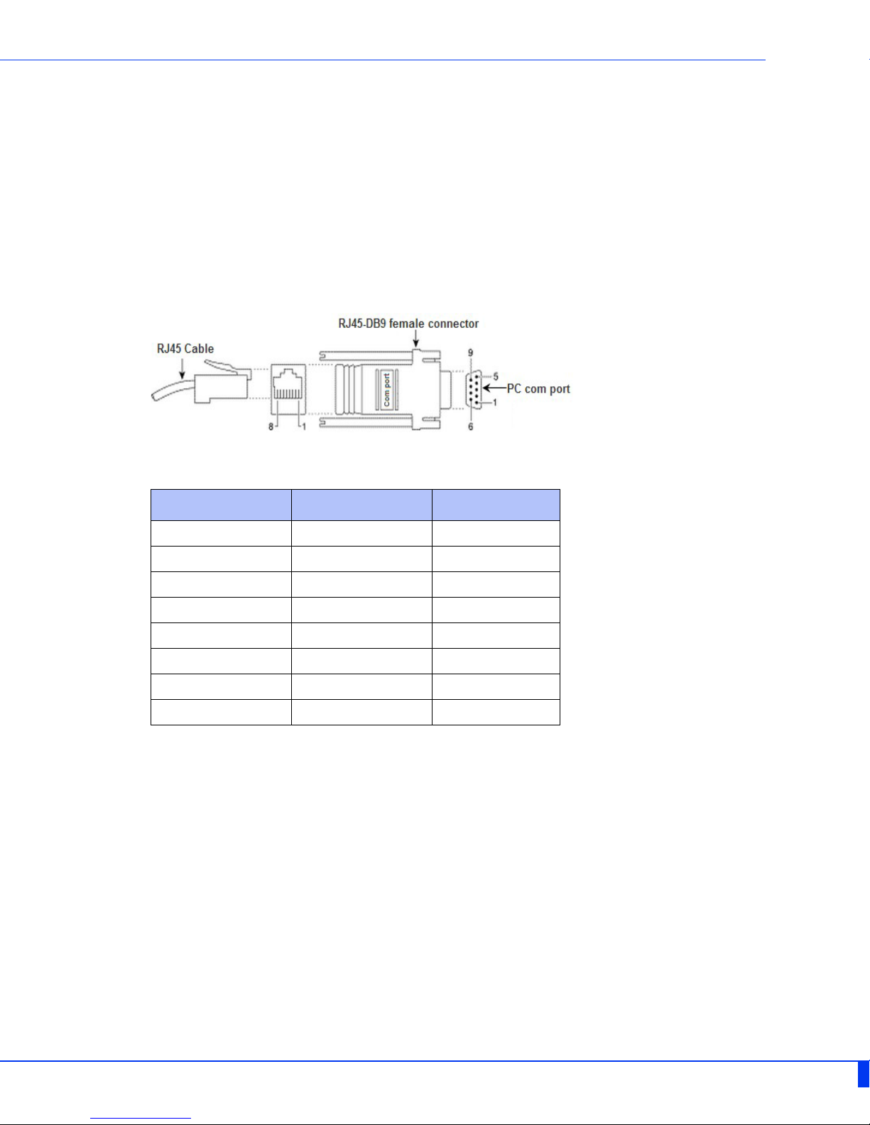
RJ45-Console Port Pinouts
The console port uses a shield cable with an 8-pin female connector (with DTE pinouts).
RJ-45 Console Function Direction
1 RTS OUT
2DTROUT
3TXDOUT
4GND-
5GND-
6RXDIN
7DSRIN
8CTSIN
Ethernet Cables
The 10/100/1000BaseT(X) ports located on the IDS switch’s front panel are used to connect to Ethernetenabled devices. These Ethernet ports will automatically adjust depending on the type of Ethernet
cable used (straight-through or cross-over), and the type of device (NIC-type or HUB/Switch-type) connected to the port.
Requirements:
• Cat 5 UTP or STP, Cat 5e cables
• 24-22 AWG (0.20mm
• Straight through or Ethernet Crossover cable
Note: An optional cable adapter is available to provide RJ45 to DB9 conversion: Perle’s optional RJ45 to
DB9-F crossover adapter model DB0020C enables a straight through Ethernet cable to connect the RJ45
console port to a PC serial port.
2
- 0.33mm2)
IDS-205F Hardware Installation Guide
Page 26
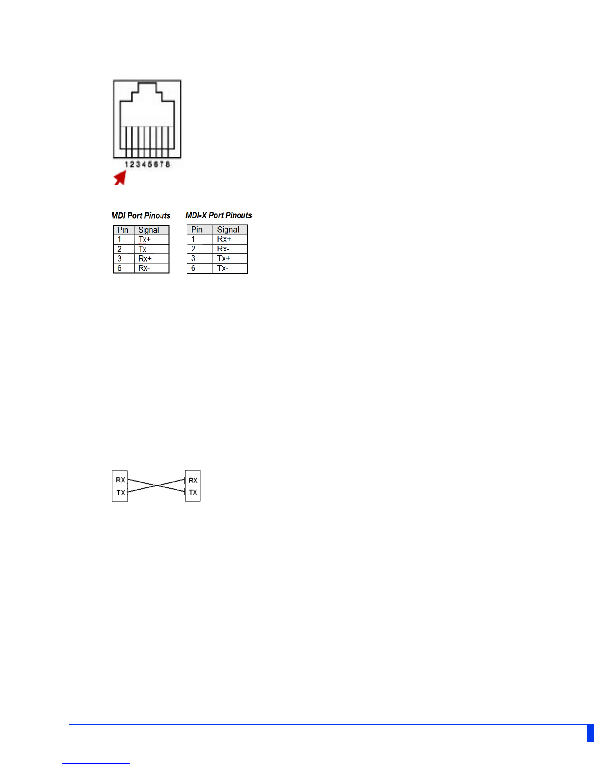
Ethnernet Connector - 8-pin RJ-45
Appendix F - Cables and Connectors 24
Fiber Port Cabling Requirements
Duplex SC or ST Connector
• Multimode 50/125 or 62.5/125 micron fiber cable
• Single mode 9/125 micron fiber cable
Simplex (BIDI, single strand) SC or ST connector
• Multimode 50/125 or 62.5/125 micron fiber cable
• Single mode 9/125 micron fiber cable
Connect the fiber cable to Port 5 on the IDS switch and the other end to a compliant fiber device. If you
are making your own fiber cables, remember that the RX on one side needs to go to TX on the other side
and vice versa. See diagram below.
IDS-205F Hardware Installation Guide
 Loading...