

Page 1

Perle 833 Remote Access Server Guide
5500114-11
Page 2

Copyrights
Copyright 1995-2002, Perle Systems Limited and its suppliers.
Apple, Macintosh, and AppleTalk are trademarks of Apple Computer Inc.
IBM, AT, CA/400, and PC Support/400 are registered trade marks of International
Business Machines Corporation.
Microsoft, MS-DOS and Windows are registered trade marks of Microsoft
Corporation.
Novell and NetWare are registered trademarks of Novell, Incorporated.
All other trademarks mentioned in this document are the property of their respective
owners.
FCC/DOC Compliance Statements
NOTE: This equipment has been tested and found to comply with the limits for a
Class A Digital Device, pursuant to Part 15 of the FCC rules and to DOC Radio
Interference Regulations, C.R.C., c1374. These limits are designed to provide
reasonable protection against harmful interference when the equipment is operated
in a commercial environment. This equipment generates, uses, and can radiate radio
frequency energy and, if not installed and used in accordance with the instruction
manual, may cause harmful interference to radio communications. Operation of this
equipment in a residential area is likely to cause harmful interference in which case
the user will be required to correct the interference at his own expense.
FCC/DOC compliance requires that all I/O cables used with Perle products be
constructed using shielded cable, metal-shelled connectors and conductive
backshells.
CAUTION: Changes or modifications to a Perle product which are not expressly
approved by Perle Systems Limited may void the user’s authority to operate the
equipment.
This device complies with Part 15 of the FCC rules. Operation is subject to the
following two conditions: (1) this device may not cause harmful interference, and (2)
this device must accept any interference received including interference that may
cause undesired operation.
Page 3

Table Of Contents
Table of Contents
Table of Contents ....................................................................................................iii
Preface...................................................................................................................... ix
About this Guide...........................................................................................................ix
About the Document Set ...............................................................................................x
Chapter 1: Introduction .......................................................................................... 1
Perle 833 Remote Access Server...................................................................................1
Supported Protocols.......................................................................................1
Dial-In............................................................................................................................1
Dial-Out.........................................................................................................................2
Manager Program ..........................................................................................................3
Initial Configuration ......................................................................................................3
Over the LAN.................................................................................................3
Direct Connect ...............................................................................................4
Dial-In Connection......................................................................................... 6
Chapter 2: Perle 833 Hardware Installation ......................................................... 7
Hardware Overview.......................................................................................................7
Perle 833 Server Models ................................................................................8
Front Panel .....................................................................................................8
LEDs ..............................................................................................................9
Hardware Installation for Ethernet Perle 833 Server ..................................................10
Hardware Installation for Token-Ring Perle 833 Server............................................. 12
Setting the IP Address .................................................................................................13
Modem Installation......................................................................................................14
System Defaults...........................................................................................................14
Chapter 3: Manager Software Installation and Setup ...................................... 15
Manager Overview ......................................................................................................15
Connection ................................................................................................... 15
Client Software ............................................................................................16
System Requirements.................................................................................................. 16
Installing Manager Software .......................................................................................17
Connecting to the Perle 833 Server .............................................................................18
Perle 833 Remote Access Server Guide iii
Page 4

Table Of Contents
In-band Connection ..................................................................................... 18
Direct Connection........................................................................................ 18
Dial-In Connection ...................................................................................... 20
Server List................................................................................................................... 20
Update Firmware ........................................................................................................ 22
Manager Main Screen................................................................................................. 23
Menu bar...................................................................................................... 24
File Menu..................................................................................................... 24
View Menu .................................................................................................. 25
Configure Menu........................................................................................... 25
Statistics....................................................................................................... 26
Event Log .................................................................................................... 26
Window Menu ............................................................................................. 27
Help Menu ................................................................................................... 28
Tool bar........................................................................................................ 28
Chapter 4: Server Configurations .......................................................................31
Configuration Overview ............................................................................................. 31
Open Configuration File ............................................................................................. 32
Configuration File Window........................................................................................ 33
Server Options ............................................................................................................ 34
Server Filter Assignment ............................................................................................ 36
Setting the date and time ............................................................................. 37
Serial Port Options...................................................................................................... 37
User List Options ....................................................................................................... 40
User Records ............................................................................................... 40
User List Access.......................................................................................... 40
Shared User Lists......................................................................................... 40
Save Configuration File .............................................................................................. 40
Download the Configuration....................................................................................... 41
Protocol Enable/Disable.............................................................................................. 42
Event Log.................................................................................................................... 42
Dialing prefix/port ...................................................................................................... 43
Packet Filtering ........................................................................................................... 43
Chapter 5: Configuring Network Protocols .......................................................47
IP Parameters .............................................................................................................. 47
iv Perle 833 Remote Access Server Guide
Page 5

Table Of Contents
IP Requirements...........................................................................................48
Configuring IP Parameters ...........................................................................49
Client IP Addresses......................................................................................50
Addresses for Direct Polling ........................................................................53
IP Static Routing ..........................................................................................55
Configuring IP Static Routing......................................................................55
IP Filter Definition ...................................................................................................... 57
Add / Edit IP Filter Definition .....................................................................58
IPX Parameters............................................................................................................59
IPX Requirements........................................................................................59
Configuring IPX Parameters ........................................................................59
IPX Static Routes ........................................................................................................61
IPX Network Services..................................................................................61
Configuring IPX Static Routing...................................................................61
MAC addresses............................................................................................................65
MAC addresses and Perle 833 .....................................................................65
Fixed MAC Addresses.................................................................................65
IPX Filter Definition....................................................................................................67
Add / Edit IPX Filter Definition ..................................................................67
AppleTalk Protocol .....................................................................................................69
NetBEUI ......................................................................................................................69
Chapter 6: User Records ....................................................................................... 71
Overview .....................................................................................................................71
Configuring a User Record.......................................................................................... 71
Shared User Lists.........................................................................................................74
Call Back Options........................................................................................................75
User Filter Assignment................................................................................................77
Dial-In Modem Pools ..................................................................................................78
Configuration Steps......................................................................................78
Chapter 7: Dial-In.................................................................................................. 81
Overview .....................................................................................................................81
Configuring Dial-In.....................................................................................................81
Using Windows 95 Dial-up Networking .................................................................82
Perle 833 Remote Access Server Guide v
Page 6

Table Of Contents
What You Need............................................................................................ 82
Configuring a New Connection................................................................... 82
Making a Dial-Up Networking Connection ................................................ 83
Call Back Options........................................................................................ 83
Using Apple Remote Access ...................................................................................... 84
Configuration............................................................................................... 84
Chapter 8: Dial-Out ...............................................................................................85
Overview..................................................................................................................... 85
Configuring Dial-Out.................................................................................................. 85
Port Dial-Out Parameters............................................................................................ 86
Configuration Steps ..................................................................................... 86
Server Dial-Out Parameters ........................................................................................ 90
Configuration Steps ..................................................................................... 90
Dial-Out Modem Pools............................................................................................... 91
Configuration Steps ..................................................................................... 91
Chapter 9: Network Administration ....................................................................93
What is SNMP?........................................................................................................... 93
Configuration Steps ..................................................................................... 94
Trap Hosts.................................................................................................... 95
Communities and Community Tables ......................................................... 95
Viewing Statistics ....................................................................................................... 97
IPX Network Numbers................................................................................ 98
Information Presented for Ports................................................................... 99
Event Log.................................................................................................................. 101
Software Upgrades.................................................................................................... 102
Chapter 10: Security ............................................................................................103
Overview................................................................................................................... 103
Server Access ............................................................................................ 103
Network Access......................................................................................... 104
PAP and CHAP.......................................................................................... 105
Call Back ................................................................................................... 106
Generic User.............................................................................................. 106
Security Services Configuration ............................................................................... 107
vi Perle 833 Remote Access Server Guide
Page 7

Table Of Contents
Administrative Privileges...........................................................................107
Network Access .........................................................................................107
User List.....................................................................................................108
Netware .....................................................................................................108
RADIUS.....................................................................................................109
External Hardware ..................................................................................... 111
Axent.......................................................................................................... 112
SecurID ......................................................................................................114
NT Domain ................................................................................................117
Generic User ...........................................................................................................118
Front Panel Lock ....................................................................................................... 120
Chapter 11: Front Panel...................................................................................... 121
Overview ................................................................................................................... 121
Front Panel Language ................................................................................ 121
Navigational Rules.....................................................................................122
Editing Fields .............................................................................................122
Menu Structure .......................................................................................................... 123
Menu Descriptions..................................................................................................... 128
Chapter 12: Custom Server Configuration ....................................................... 133
Creating a Custom Modem Configuration ................................................................ 133
Modem String Commands .........................................................................134
Changing Link Control Protocol Parameters ............................................................135
Changing the Async Control Map .............................................................................137
Appendix A: Pinout and Cable Diagram........................................................... 139
Asynchronous Connector Pinout...............................................................................139
Pinout .........................................................................................................139
Null modem cable ..............................................................................................140
Introduction................................................................................................140
Diagram......................................................................................................140
Appendix B: Hardware Specifications............................................................... 141
Glossary ................................................................................................................ 143
Index...................................................................................................................... 149
Perle 833 Remote Access Server Guide vii
Page 8

Table Of Contents
viii Perle 833 Remote Access Server Guide
Page 9

Preface
About this Guide
This guide is intended for network administrators or supervisors who need to know how to install
and manage a Perle 833 Remote Access Server on their network. This guide assumes that the network
administrators or supervisors have a solid understanding of their own network environments,
including medium type (Ethernet or Token Ring) and protocols (IP, IPX, or AppleTalk). This guide
is also for the advanced network user.
In this guide you will read about:
• System Overview
Chapter 1 describes the Perle 833 Remote Access Server set of products, features and uses.
• Hardware Installation
Chapter 2 contains the description of the Perle 833 hardware unit and its installation instructions.
• Manager Installation
Chapter 3 introduces the Perle 833 Remote Access Manager program. Instructions on
installation and making a connection to a Perle 833 Remote Access Server are provided.
• Configuration
Chapters 4, 5 and 6 describe the basic parameters that need to be configured on the Perle 833
Remote Access Server. These include naming the server, configuring serial port, LAN protocols
and users.
Chapter 12 provides details on Advanced configuration items that can be used to enhance the
operation of the Perle 833.
•Dial-In and Dial-Out
Chapters 7 and 8 provide details on enabling the Dial-In and Dial-Out services of the Perle 833.
Information is also provided about third party dial-in clients.
• Network Administration
Chapter 9 describes features of the Perle 833 System that allow network administrators to
monitor the status of the Perle 833 and its users. This includes SNMP statistics, Perle 833
statistics and a log file of activity on the server.
Perle 833 Remote Access Server Guide ix
Page 10

About The Document Set
• Security
Chapter 10 describes the security features supported by the Perle 833 System and the procedures
for configuring these features.
• Front Panel
The front panel of the Perle 833 can be used for limited configuration and viewing of statistics.
Chapter 11 describes the uses and operation of the front panel.
About the Document Set
This guide is part of a document set that includes the following publications:
• Perle Remote User’s Guide
• Perle 833 Dial-Out User’s Guide
• Perle 833 Remote Access Server Guide
x Perle 833 Remote Access Server Guide
Page 11

Chapter 1: Introduction
This chapter introduces the Perle 833 Remote Access Server set of products, features and functions.
Perle 833 Remote Access Server
The Perle 833 Remote Access Server is an interface device which allows access to Local Area
Networks (LANs) from the telephone network. Users can dial-in to the LAN from a remote site or
dial-out from the LAN to access a remote host.
Models are available for both Ethernet and Token-Ring LANs, in 2, 4, or 8 port configurations.
Supported Protocols
The LAN connections support the following network protocols
• Novell Internetwork Packet Exchange (IPX)
• Internet Protocol (IP)
• AppleTalk
Dial-In
• NetBios Extended User Interface (NetBEUI)
• Logical Link Control (LLC) and 802.2.
The Dial-In feature allows remote users, using client software, to access a LAN and perform tasks
as if they were directly attached to it, using inexpensive voice-grade telephone circuits and
asynchronous modems.
Remote users can connect to the Perle 833 with a modem using a wide variety of PPP clients or the
Apple Remote Access Client. Among the PPP clients supported are the Perle Remote (for DOS and
Windows 3.x), and the Windows 95 and Windows NT dial-up Networking clients. The Perle Remote
software is provided with the Perle 833 Remote Access Server. See the Perle Remote User’s Guide
(for DOS and Windows 3.x) for more information on the dial-in function. For more information on
other client software, see “Chapter 7: Dial-In” on page 81.
Perle 833 Remote Access Server Guide 1
Page 12
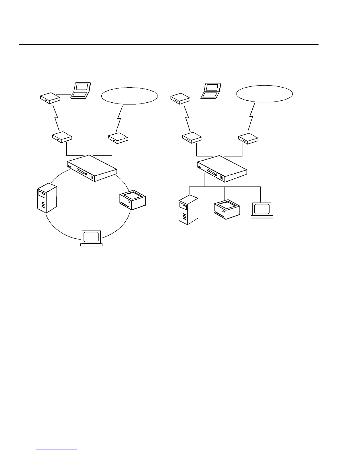
Dial-Out
s
Perle 833 Network Topology
Token Ring LAN Access
Ethernet LAN Access
NetWARE
Windows® NT,
Unix, IBM
Remote Client(s)
Token Ring LAN
LAN Workstations *
Fax, Internet, BBS,
On-Line services
Async modems or
ISDN terminal adapters
speeds up to 115 kbps
Perle 833 for Token
Ring (2, 4 or 8 ports)
Network
Printers
NetWARE
Windows® NT,
Unix, IBM
Remote Client(s)
Ethernet LAN
Network
Printers
Fax, Internet, BBS,
On-Line services
Async modems or
ISDN terminal adapter
speeds up to 115 kbps
Perle 833 for Ethernet
(2, 4 or 8 ports)
LAN Workstations *
Management software can be run from either a local or remote Windows® PC, Windows® 95 or Windows® NT
*
Dial-Out
The Dial-Out function allows users on a LAN workstation to connect to a destination that is external
to their LAN. This is done by dialing out via a Perle 833 modem instead of a modem attached
directly to the user’s PC. The user can connect to a BBS, internet provider or any other service
accessible by the telephone network
The benefit of sharing these modems across a network is that they can make efficient use of the
hardware and phone lines that are already installed on the network.
The Dial-Out feature is accessed using the Perle 833 Dial-Out software. See the Dial-Out User’s
Guide for more details on the dial-out function.
2 Perle 833 Remote Access Server Guide
Page 13

Manager Program
The Perle 833 Manager software is included with the Perle 833 Remote Access Server. It is a
Windows based program that allows network administrators to configure, monitor and manage the
Perle 833 servers on the LAN.
Initial Configuration
In order to configure the unit for the first time, the PC on which the manager is running must
establish communication with the target Perle 833 server. This can be done in one of three ways:
• Over the LAN (Inband)
By connecting both the PC and the server to the LAN, communications can be established
between the two over the LAN using either IP or IPX protocols.
• Direct Connect
By using the direct connect cable provided with the unit, a PC can establish a serial link to the
server via one of the server’s serial connectors.
Chapter 1: Introduction
• Dial-in Connection
By connecting a modem to both the PC and the server, the PC can establish a link.
The following is an overview of the general steps required for each method.
Over the LAN
1. Server Hardware Setup.
Follow the hardware installation procedures as outlined in Chapter 2.
2. For IP networks, set the server’s IP address.
If you intend to assign an IP address to your server via BOOTP or RARP, you do not need to
do anything here since these are the defaults. Otherwise, you will need to enter an IP address
and subnet mask from the front panel under the Configuration LAN Menu. See Chapter 11 for
information on using the front panel.
3. Install the manager.
Install the manager on a LAN workstation. Ensure that the workstation is properly configured
for IP or IPX. If the manager PC is setup for IP, be sure it has an IP address. See Chapter 3 for
Perle 833 Remote Access Server Guide 3
Page 14

Initial Configuration
further information.
4. Start up the manager.
The Perle 833 manager after startup will automatically find the server on the LAN using IP, IPX,
or both.
5. Login to the server.
Select the server from the list. Then login as superusr with no password.
Direct Connect
Windows 3.1
1. Install the Perle Remote software. Refer to the Perle Remote User’s Guide (for DOS and
Windows 3.x) for details.
2. Configure the Perle Remote software for direct connect and 38400 baud rate.
3. Install the manager.
Refer to Chapter 3 for further information. Reboot your PC.
Note: If the manager PC is to use an IP connection, it must be configured with an IP address.
4. Connect the PC and the server.
Connect the PC to the server using the supplied direct connect cable.
5. Power up the Perle 833.
6. Establish the connection.
Using the Perle Remote Dialer (Windows or DOS), connect to the server. Login as superusr
with no password.
Once this is completed, startup the manager. After selecting and connecting to the Perle 833,
you will be asked to log in a second time. Use superusr again.
4 Perle 833 Remote Access Server Guide
Page 15

Chapter 1: Introduction
Windows 95
1. Install the Manager on your PC.
2. If your Windows 95 Modem List does not have a direct connect modem type, do the following
steps:
a) From the modem section on the Control Panel, select Add modem.
b) Choose to select from a list instead of auto detect.
c) From the modem selection list, select Have Disk.
d) Specify the drive and installation directory of the Perle 833 Manager. (Default is
C:\Perle833).
e) From the model list choose Direct Connection.
f) Select your COM port.
3. Set up a dial-up networking connection using the direct connection created above. Set the baud
rate at 38400.
4. In your dial-up network connection, make sure that you have enabled either IP or IPX.
5. For IP connection, set your TCP/IP settings so that the client (your PC) is supplying its own IP
address and enter the address you wish to use.
6. If you are using an IP connection, you will need to set up an IP address and subnet mask in the
Perle 833 server. This can be done through the Front Panel under the Configuration LAN m en u.
See Chapter 11 for information on using the Front Panel.
7. Using the supplied cable, connect the PC to the Perle 833 server.
8. From Dialup networking, start the Dial-up Session. Login to the Perle 833 as Superusr with no
password.
9. Start up the manager. After selecting and connecting to the Perle 833, you will be asked to log
on a second time. Use Superusr again.
Perle 833 Remote Access Server Guide 5
Page 16

Initial Configuration
Dial-In Connection
If neither of the above two methods is possible, you can set up a dial-in connection.
1. Set up the Perle 833.
Using the Front Panel, configure the port parameters to best suit the modem you are using. Note
that the modem selection at this stage is limited. You will need to use the Hayes selection. Cycle
power in the Perle 833 to ensure parameters take effect.
2. Connect your modem.
3. Set up your client software.
For information on setting up the Perle Remote, refer to the Perle Remote User’s Guide. For
Windows 95 or Windows NT, refer to your Windows documentation and Chapter 7 of this guide.
4. Establish the connection, logging on as Superusr with no password.
6 Perle 833 Remote Access Server Guide
Page 17

Chapter 2: Perle 833 Hardware Installation
In this chapter you will learn how to install the Perle 833 Remote Access Server. You will read
about:
• Hardware Overview—cabling requirements, modems, telephone lines, etc.
• LEDs
• Front Panel Operation
• Hardware Installation for Ethernet
• Hardware Installation for Token-Ring
• System Defaults
Hardware Overview
The following items were shipped to you with your Perle 833.
• Perle 833 Remote Access Server
• AC Power Cord
• Null Modem Cable
• Perle 833 Manager (CD-ROM)
• Perle Remote (CD-ROM)
• Perle 833 Dial-Out (CD-ROM)
• Documentation Set
You will also require the following items in order to complete the hardware installation.
Modems
Analog modems capable of at least 14.4 Kbps are recommended, or other asynchronous terminating
device, such as ISDN terminal adapters for each serial port to be used.
Cables
Modem Connection: Cables required to connect the modems to the RS-232 DB9 connectors on the
Perle 833.
Perle 833 Remote Access Server Guide 7
Page 18
Hardware Overview
Ethernet Connection: Cables required to attach the Ethernet LAN to either the RJ-45 connector for
10Base-T, the BNC connector for 10Base-2 (Thinnet) or the AUI connector for 10Base-5 thick
Ethernet LAN’s.
Token Ring Connection: Cables required to attach the Token Ring LAN to either the RJ45
connector for UTP connections or DB9 connection for STP connections.
Telephone System: Cable will be required to attach the modems or Terminal adapters to the
telephone network.
Perle 833 Server Models
There are three different Perle 833 models. Each model has an Ethernet and a Token-Ring version.
• Perle 833/2e or /2t - Two remote ports
• Perle 833/4e or /4t - Four remote ports
• Perle 833/8e or /8t - Eight remote ports
The ‘e’ or ‘t’ at the end of the module number indicates an Ethernet or Token-Ring unit.
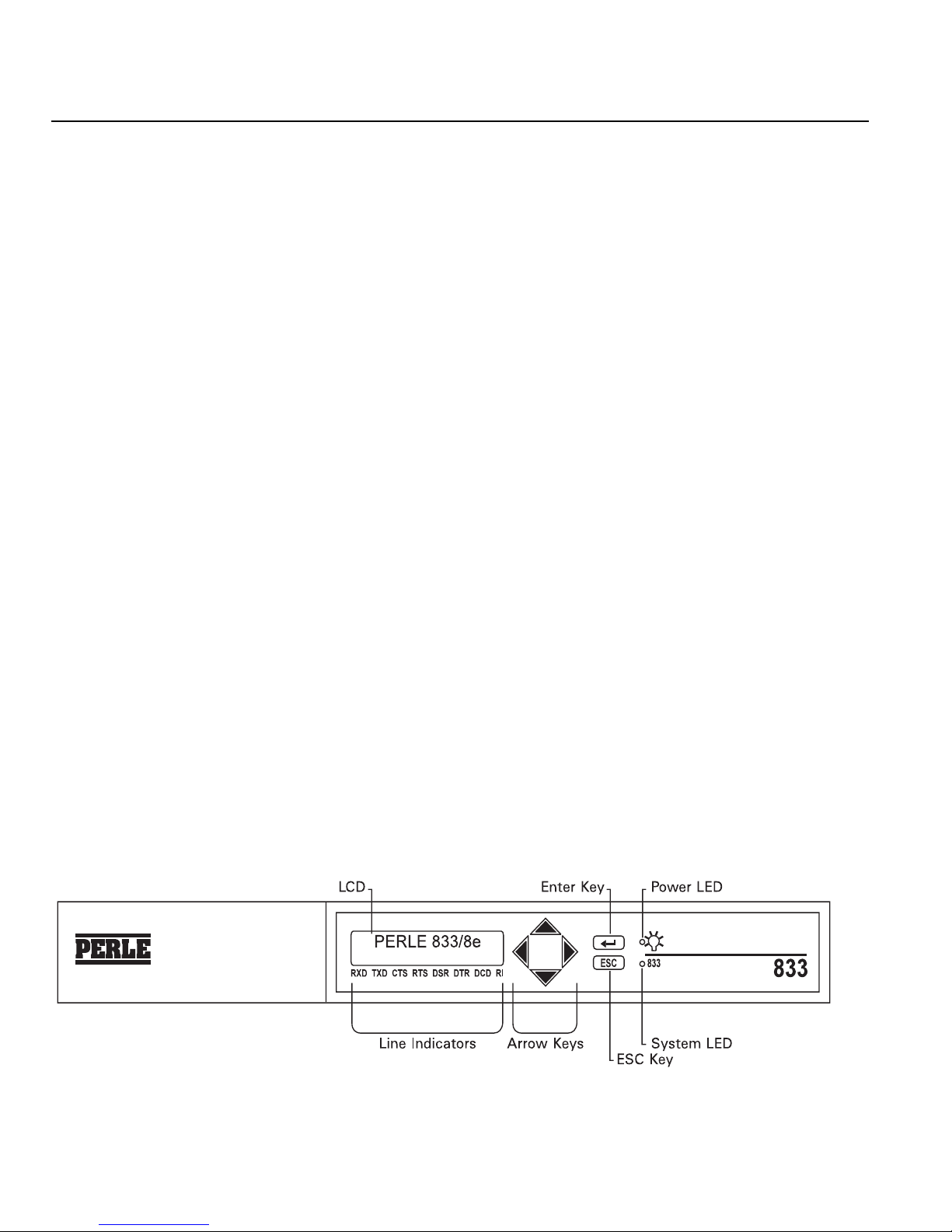
Front Panel
The Front Panel of the Perle 833 consists of a keypad and an LCD display. This front panel is
common to all models of Perle 833 and can be used for obtaining system status and statistics as well
as providing some limited configuration capabilities.
Use the
Use the UP and DOWN arrow keys to view the options within that menu. Press the ESC key once
to return to the previous menu, and press it several times to return to the Perle 833 main menu. For
more information about navigation and editing fields in the front panel display, see “Chapter 11:
Front Panel” on page 121.
When the unit is first powered up the LCD display will cycle through the list of languages that it
supports. Wait until the appropriate language is displayed and then press
↵ (Enter) key to select a menu that is displayed on the LCD panel or to confirm a selection.
↵.
8 Perle 833 Remote Access Server Guide
Page 19
LEDs
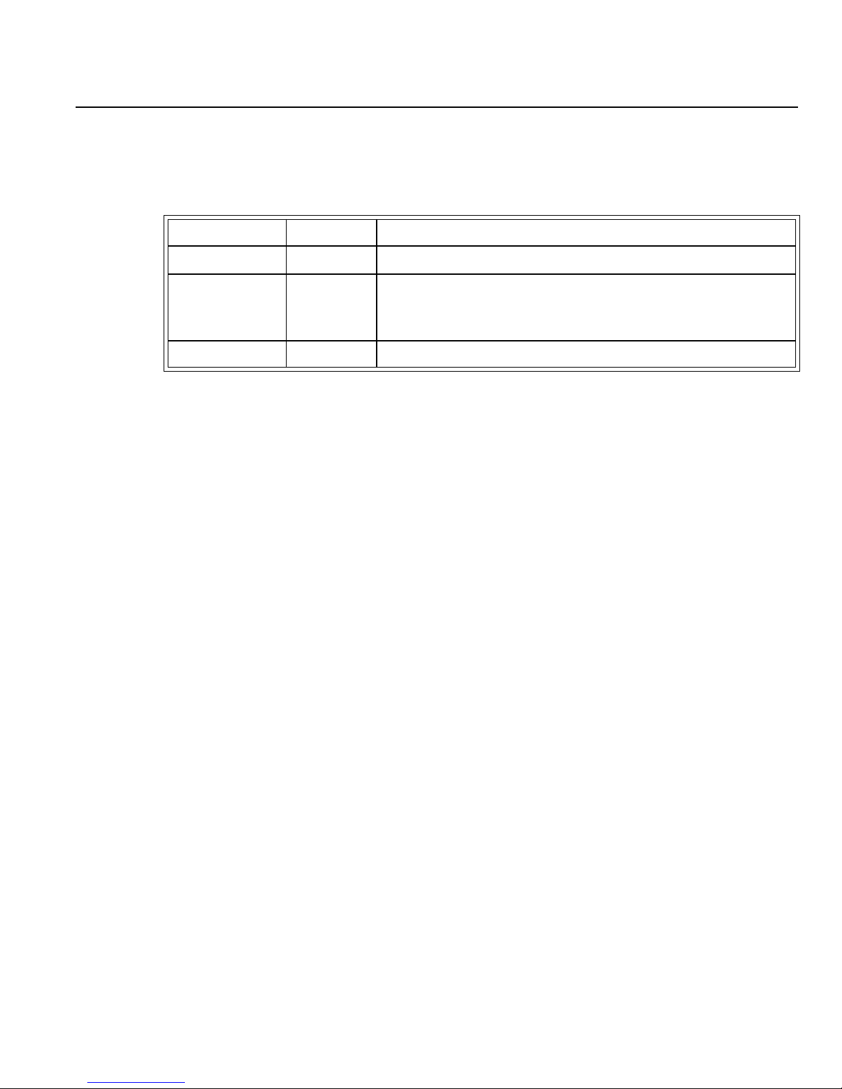
The Perle 833 front and back panel LEDs are described below.
LED Location Function
Power (green) Front Indicates the Perle 833 is connected to AC power.
System (green) Front Blinks continuously when the Perle 833 is operational. Under
normal conditions, this happens approximately 30 seconds
after the unit is plugged in.
Link (yellow) Back Indicates a connection with a LAN.
Chapter 2: Perle 833 Hardware Installation
Perle 833 Remote Access Server Guide 9
Page 20
Hardware Installation for Ethernet Perle 833 Server
Hardware Installation for Ethernet Perle 833 Server
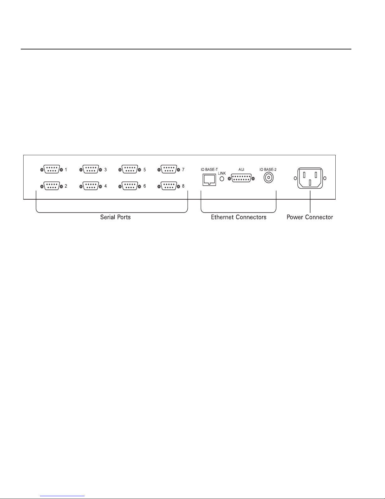
The installation of the Ethernet server involves the following steps.
1. Connect the Ethernet cable to the proper Ethernet connector on the back panel of the Perle 833
(8 port model is shown).
Ethernet Back Panel
Note: Back panels for 2e, 4e, and 8e models differ only in the number of serial ports.
2. Plug the power cable into the back of the Perle 833 and into AC power.
Note: Always connect the power cable into the back of the Perle 833 before connecting it to
the power source, and always disconnect the power cable from the power source before
disconnecting it from the back of the Perle 833.
After a moment, the System (833) LED starts blinking and the LCD begins scrolling through
the list of available languages for front panel display. When the language you wish to display
appears, press
menu, which displays “Perle 833/ne” (where n represents the number of serial ports).
3. If you are using 10BASE-T or 10BASE-2 go to step 4. If you are using 10BASE-5 (AUI), use
the front panel keypad to change the Ethernet connection type.
To change the Ethernet connection type:
a) From the main menu, use the
b) From the Configuration menu, use the
Configuration LAN menu.
c) From the Configuration LAN main menu, use the
The LCD displays the current connection type setting. Press the
↵. Confirm your selection by pressing ↵ again. The LCD then displays the main
↵ key to select the Configuration menu.
↵ key, then the DOWN arrow key to access the
↵ key to access the Connection menu.
↵ key to modify the setting.
10 Perle 833 Remote Access Server Guide
Page 21

Chapter 2: Perle 833 Hardware Installation
d) Using the UP and DOWN arrow keys, select the 10BASE-5 (AUI) option, and press ↵ to
confirm your selection.
e) Reset the system by doing the following:
i) Press the ESC key until you return to the Configuration menu.
ii) From the Configuration main menu, use the
access the Configuration System menu.
iii) Select the System Reset option, and press
main menu is then displayed.
4. The Link LED should be blinking yellow and the front panel should be displaying the main menu
in the selected language.
5. Go to “Setting the IP Address” on page 13.
↵ key, then the DOWN arrow key to
↵ twice to reset the system. The Perle 833
Perle 833 Remote Access Server Guide 11
Page 22
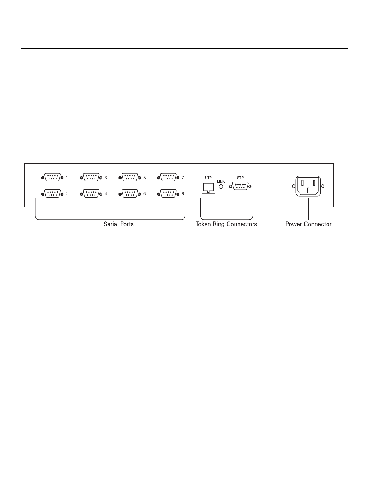
Hardware Installation for Token-Ring Perle 833 Server
Hardware Installation for Token-Ring Perle 833 Server
The installation of the Token-Ring server involves the following steps.
1. Plug the power cable into the power connector on the back panel of the Perle 833 (8 port model
is shown).
Note: Always connect the power cable into the back of the Perle 833 before connecting it to
the power source, and always disconnect the power cable from the power source before
disconnecting it from the back of the Perle 833.
Token-Ring Back panel
Note: Back panels for 2t, 4t, and 8t models differ only in the number of serial ports.
After a moment, the System (833) LED starts blinking and the LCD begins scrolling through
the list of available languages for front panel display. When the language you wish to display
appears, press
menu, which displays “Perle 833/nt” (where n is the number or serial ports).
2. Use the front panel to set the Token-Ring speed to match the speed of your Token-Ring LAN.
a) From the main menu, use the
b) From the Configuration menu, use the
Configuration LAN menu.
c) From the Configuration LAN menu, use the
LCD displays the current connection speed setting. Press the
d) Use the UP and DOWN arrow keys to until the appropriate speed is displayed, then press
the
↵ key to select the connection speed.
e) Reset the system by doing the following:
i) Press ESC until you return to the Configuration menu.
↵. Confirm your selection by pressing ↵ again. The LCD then displays the main
↵ key to select the Configuration menu.
↵ key, then the DOWN arrow key to access the
↵ key to access the Connection menu. The
↵ key to modify the setting.
12 Perle 833 Remote Access Server Guide
Page 23

Chapter 2: Perle 833 Hardware Installation
ii) From the Configuration menu, use the ↵ key, then the DOWN arrow key to access
the Configuration System menu.
iii) Select the System Reset option, and press
main menu is then displayed.
3. The Link LED on the back panel should be blinking yellow and the front panel should be
displaying the main menu in the selected language.
4. Connect the Token-Ring cable to the proper Token-Ring connector on the back panel of the
Perle 833.
5. Proceed with "Setting the IP Address".
Setting the IP Address
The Perle 833 will need to have an IP address if it will be operating in an IP network. If you are not
operating in an IP network or if the network supports a BOOTP or RARP server to supply an IP
address to the Perle 833, skip the next step.
1. From the main menu, use the
2. From the Configuration menu, use the
Configuration LAN menu.
↵ twice to reset the system. The Perle 833
↵ key to select the Configuration menu.
↵ key, then the DOWN arrow key to access the
3. From the Configuration LAN main menu, use the
the IP Address menu.
4. Press the
keys to position the cursor. Then use the Up or Down arrow keys to change the value of a digit.
5. Reset the system by doing the following:
a) Press ESC until you return to the Configuration menu.
b) From the Configuration menu, use the
c) Select the System Reset option, and press
↵ key to start editing the IP Address of the Perle 833. Use the Left and Right arrow
Configuration System menu.
menu is then displayed.
Perle 833 Remote Access Server Guide 13
↵ key, then the DOWN arrow key to access
↵ key, then the DOWN arrow key to access the
↵ twice to reset the system. The Perle 833 main
Page 24

Modem Installation
Modem Installation
Install each modem that is required as follows:
1. Connect the modem cable from the serial port of the modem to the proper serial port of the server.
2. Follow the modem’s installation instructions to power up the modem and connect it to the
telephone network.
System Defaults
The Perle 833 defaults are listed below. The default settings can be changed from the front panel or
the Manager program.
System
Front Panel Lock—no password
Language—not set
Ports
All ports enabled
Modem type - Direct
38,400 baud rate
Broadcast enabled
Multicast enabled
Dial-in enabled
Head and Address compression enabled
LAN
Connection - BNC/10Base-T auto-sensing (Ethernet Unit)
- LAN speed - 16 Mbs (Token-Ring unit)
IP address - none
No Subnet Mask
RARP enabled
BOOTP enabled
14 Perle 833 Remote Access Server Guide
Page 25

Chapter 3: Manager Software Installation and Setup
This chapter describes the Perle 833 Manager program, its installation procedure, and method of
connecting to the Perle 833. In this chapter you will read about:
• Manager Overview
• System Requirements
• Installing Manager Software
• Connecting to the Server via In-band and Serial links
• Manager Main Screen
Manager Overview
The Perle 833 Manager software is a Microsoft Windows application used to configure, monitor and
manage Perle 833 servers. The Perle 833 Manager can do the following:
• Create configuration files to be downloaded to Perle 833 hardware units—different
configurations can be made, saved, and downloaded.
• Upload a Perle 833’s configuration so it can be saved, modified, used in other Perle 833s, or
compared to other configurations.
• Display statistics for a Perle 833.
• Display event logs for a Perle 833.
• Download new firmware to a Perle 833.
Connection
The Manager requires a connection to be established with a Perle 833 remote access server. This can
be accomplished in any of the following ways:
• In-band Connection: Connect a PC to the same network that the Perle 833 server is connected
to, and then use the Manager software to establish an in-band connection using IP or IPX. This
will depend on the network software running on the Manager PC.
• Direct Connection: Use the null modem cable provided with the Perle 833 unit to connect the
PC directly to a Perle 833 serial port, and then use Dial-in client software to establish the
connection.
Perle 833 Remote Access Server Guide 15
Page 26

System Requirements
• Modem Serial Connection: Use modems and Dial-in client software to connect the Manager
PC to the Perle 833 over the telephone network.
Client Software
The Manager software will run over the following clients when using a serial connection:
• Perle Remote (for Dos and Windows 3.x)
(See the Perle Remote User’s Guide for details on installation and setup).
• Windows 95 Dial-Up Networking Client
• Windows NT 3.5 or 4.0 Dial-Up Client
System Requirements
The minimum requirements to use the Perle 833 Manager software are:
• PC-compatible 80386 or faster computer with the following:
• Hard drive with at least 2 MB free storage space
• Microsoft Windows 3.1 or higher with MS-DOS version 5.0 or higher
or
Windows 95
or
Windows NT 4.0
•4 MB RAM
• Windows-compatible mouse
For an in-band connection - IP
• A working IP connection to the LAN. For Windows 3.1 users, a TCP/IP stack is provided on
the Manager disks.
For an in-band connection - IPX
• A working IPX connection to the LAN.
For a Direct connection
• An unused serial (COM) port on the Manager PC. A buffered serial port (for example, one that
uses 16550 UARTs) is strongly recommended. Serial ports on older devices are usually not
16 Perle 833 Remote Access Server Guide
Page 27

Chapter 3: Manager Software Installation and Setup
buffered.
• Dial-In Client software.
• Null modem cable that was supplied with the Perle 833 Server. This is connected between the
serial port of the PC running the manager and a serial port on the Perle 833. For more information
on the Null modem cable see “Appendix B: Hardware Specifications” on page 141.
For a modem serial connection
• An unused serial (COM) port on the Manager PC. A buffered serial port (for example, one that
uses 16550 UARTs) is strongly recommended. Serial ports on older devices are usually not
buffered.
• Dial-In Client software.
• A modem cable for connection between the PC serial port and a modem.
• Analog modems capable of at least 14.4 Kbps are recommended, or other asynchronous
terminating devices, such as ISDN terminal adapters.
• Voice grade telephone lines or high speed service like ISDN.
Installing Manager Software
To install the Perle 833 Manager software, follow these steps.
1. Start Microsoft Windows.
2. Place the Perle 833 Manager CD-ROM in the CD-ROM drive.
3. Windows 3.1
In Program Manager, choose Run from the File menu, type the CD-ROM drive letter (i.e.,
D:\setup) and press Enter.
Windows 95
Click the Start button , click Run, type the CD-ROM drive letter (i.e. ,
Enter.
4. Perform the installation by following the prompts that appear on the screen.
D:\setup ) and press
Perle 833 Remote Access Server Guide 17
Page 28

Connecting to the Perle 833 Server
Connecting to the Perle 833 Server
In-band Connection
IP
The Perle 833 needs an IP address before the Manager can make a connection. This address can be
acquired in the following ways:
• The Perle 833 server will try to acquire an IP address from a BOOTP server or an RARP server
on the LAN.
• If the above step fails, then the configured IP address is used. By default, the Perle 833 does not
have a configured IP address.
• If an IP address has not been set in the Perle 833, then this must be done. An IP address can be
set by using the Front Panel. See “Chapter 11: Front Panel” for instructions.
IPX
Nothing needs to be set up on the server to establish an IPX connection.
Direct Connection
Windows 3.1
1. Install the Perle Remote software. Refer to the Perle Remote User’s Guide (for DOS and
Windows 3.x) for details.
2. Configure the Perle Remote software for direct connect and 38400 baud rate.
3. Connect the PC and the server.
Connect the PC to the server using the supplied direct connect cable.
4. Power up the Perle 833.
5. Establish the connection.
Using the Dialer (Windows or DOS), connect to the server. Login as superusr with no password.
Once this is completed, start up the manager. After selecting and connecting to the Perle 833,
you will be asked to log in a second time. Use superusr again.
18 Perle 833 Remote Access Server Guide
Page 29

Chapter 3: Manager Software Installation and Setup
6. When the connection is established, start Perle 833 Manager.
Windows 95
1. Install the Manager on your PC.
2. If your Windows 95 Modem List does not have a direct connect modem type, do the following
steps:
a) From the modem section on the Control Panel, select Add modem.
b) Choose to select from a list instead of auto detect.
c) From the modem selection list, select Have Disk.
d) Specify the drive and installation directory of the Perle 833 Manager. (Default is
C:\Perle833).
e) From the model list, choose Direct Connection.
f) Select your COM port.
3. Set up a dial-up networking connection using the direct connection created above. Set the baud
rate at 38400.
4. In your dial-up network connection, make sure that you have enabled either IP or IPX.
5. For IP connection, set your TCP/IP settings so that the client (your PC) is supplying its own IP
address and enter the address you wish to use.
6. If you are using an IP connection, you will need to set up an IP address and subnet mask in the
Perle 833 server. This can be done through the Front Panel under the Configuration LAN menu.
See chapter 11 for information on using the Front Panel.
7. Using the supplied cable, connect the PC to the Perle 833 server.
8. From Dialup networking, start the Dial-up Session. Login to the Perle 833 as superusr with no
password.
9. Start up the manager. After selecting and connecting to the Perle 833, you will be asked to log
on a second time. Use superusr again.
Perle 833 Remote Access Server Guide 19
Page 30
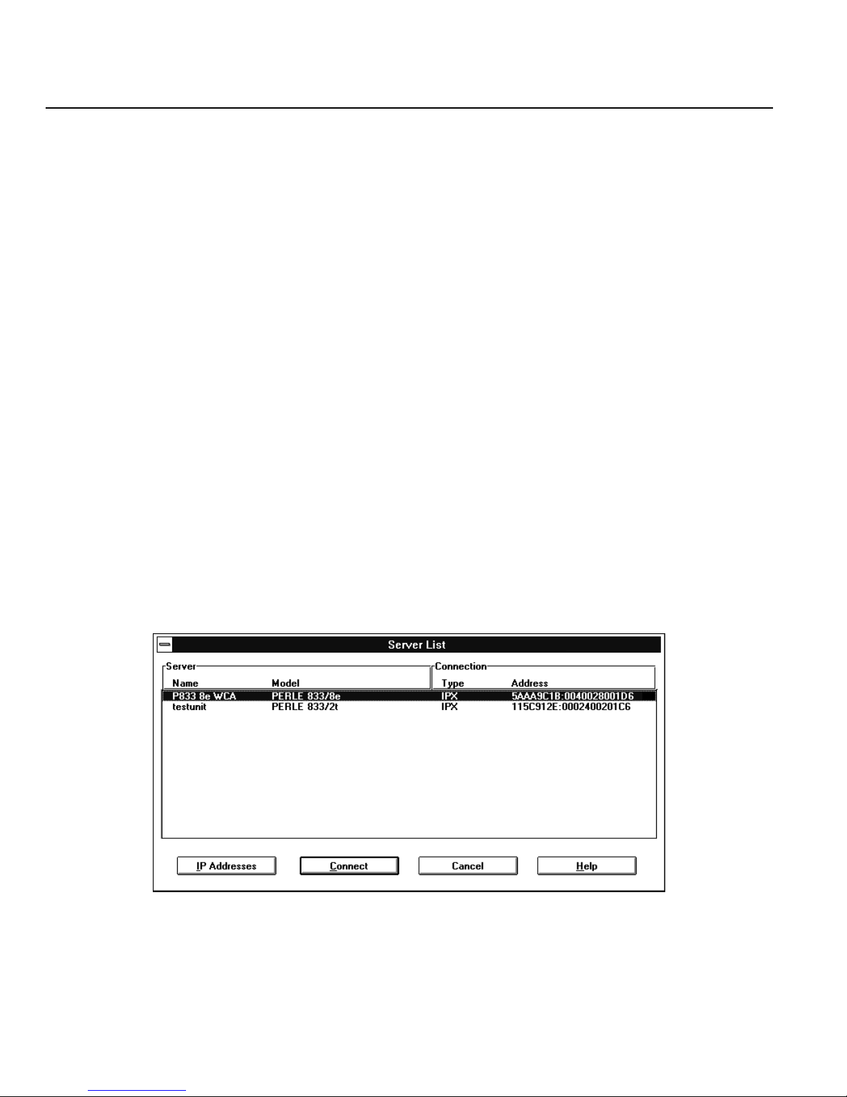
Server List
Dial-In Connection
If neither of the above two methods is possible, you can set up a dial-in connection.
1. Set up the Perle 833.
Using the Front Panel, configure the port parameters to best suit the modem you are using. Note
that the modem selection at this stage is limited. You will need to use the Hayes selection. Cycle
power in the Perle 833 to ensure parameters take effect.
2. Connect your modem.
3. Set up your client software.
For information on setting up the Perle Remote, refer to the Perle Remote User’s Guide. For
Windows 95 or Windows NT, refer to your Windows documentation and Chapter 7 of this guide.
4. Establish the connection, logging on as superusr with no password.
Server List
Once the Perle 833 Manager is running, it automatically locates all Perle 833 servers and displays
them in the Server List window. This is accomplished by sending out a broadcast message using the
following connection types or protocols: IP , and IPX.
To complete the connection to a server:
1. Highlight the server that you want to connect to and click Connect.
20 Perle 833 Remote Access Server Guide
Page 31
Chapter 3: Manager Software Installation and Setup
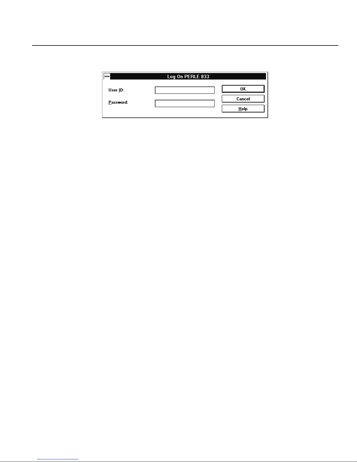
2. The Log On dialog box will appear.
3. Enter the User ID and Password for the selected server and click OK.
Note: The default name for an unconfigured Perle 833 server is: superusr - no password.
You will be required to set a password when you first configure the server.
4. If the User ID and Password are verified, then the Manager main screen is displayed.
Note: If the server you are connecting to is a new unit, you will be required to download
firmware to it before you can begin configuring.
5. A user can elect not to connect to a server by clicking on Cancel in the Server List window.
The Manager main screen is displayed without the Get Configuration and Statistics buttons.
6. If your network contains IP routers that do not route broadcast messages, then click the IP
Addresses button to configure IP Addresses for Direct Polling. See “Addresses for Direct
Polling” on page 53 for instructions.
Perle 833 Remote Access Server Guide 21
Page 32
Update Firmware
Update Firmware
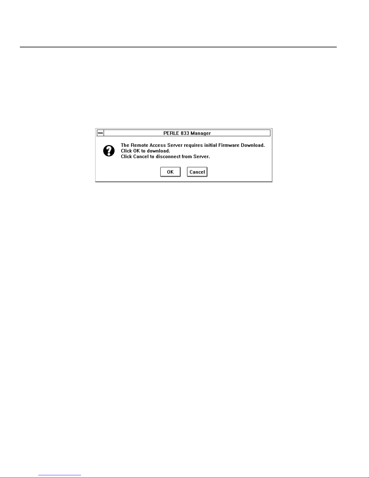
A new Perle 833 from the factory will have a base version of the operating code (firmware). This
firmware version can not be configured by the Manager and must be updated to a working version.
The base version is automatically detected when the Manager makes a connection to a new Perle 833
and superusr is used to log on. This process can take up to two minutes at 38400 baud. The
following dialog box appears:
1. Click OK to start the download process.
2. After the firmware has been downloaded, the Perle 833 will reset itself. Wait five minutes before
trying to connect to the server again for configuration.
3. If the Cancel button is clicked, the Manager will disconnect from the Perle 833 and display the
Server list again.
22 Perle 833 Remote Access Server Guide
Page 33
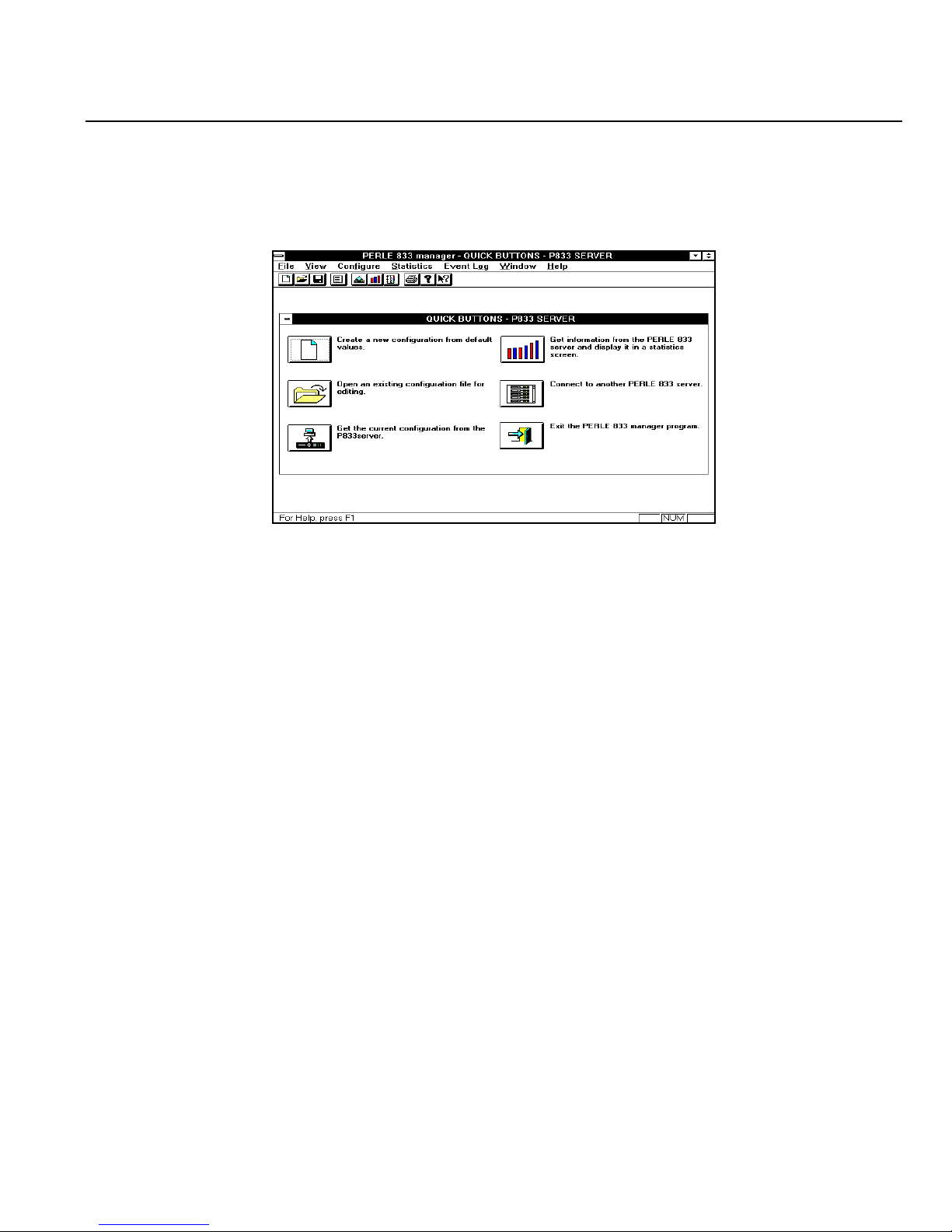
Manager Main Screen
The Perle 833 Manager main screen contains menus and the following tools and windows.
Menu Bar
Tool Bar
Quick Button
Window
Status Bar
Chapter 3: Manager Software Installation and Setup
Menu bar
Contains menus that control the Manager and configure Perle 833s. The Menu bar contains the
following menus—File; View; Configure; Statistics; Event Log; Window; and Help.
Tool bar
Makes it easier to perform some of the most-used menu functions.
Quick Buttons window
A quick way to use the main functions of Perle 833 Manager. Each function is represented by a
button. The Get Configuration and Statistics buttons are not available when a Perle 833 is not
connected.
Status bar
Gives information about menus and menu items when they are selected, and about the status of
some keys on the keyboard.
Perle 833 Remote Access Server Guide 23
Page 34

Manager Main Screen
Menu bar
The menu bar contains all of the menus available when running the Manager. Each menu contains a
list of options that drop down from the Menu title. Some of the menu items are only active when a
configuration file is open.
File Menu
The following options appear under the File menu:
New
Create a new configuration.
Open
Open an existing configuration.
Close
Close the selected configuration file.
Server List
Show all Perle 833 servers found.
Quick Buttons
Display the Quick Buttons window.
Save
Save the currently-selected configuration file.
Save As
Save the currently-selected configuration file as a new file.
Print
Print the currently-selected configuration file.
24 Perle 833 Remote Access Server Guide
Page 35

Print Preview
Show a preview of the currently-selected configuration file.
Print Setup
Select a different printer or change the printer setup.
Numbered file names
The most recent files that were opened are listed here. As a convenience, choose one to open
that file.
Exit
Quit Perle 833 Manager. If unsaved changes have been made to any files, you will be prompted
to save or cancel the changes.
View Menu
Chapter 3: Manager Software Installation and Setup
The following options appear under the View menu:
Tool Bar
This option toggles the tool bar (just below the menu bar) off and on. When the tool bar is
displayed, there is a check mark next to this option.
Status Bar
This option toggles the status bar (at the bottom of the screen) off and on. When the status bar
is displayed, there is a check mark next to this option.
Configure Menu
The Configure menu applies to the Perle 833 to which the Manager is connected, and not to any
configuration file. If a Perle 833 is not connected, the options on this menu are not available. The
following options appear under the Configure menu:
Get Configuration
Upload the configuration from the connected server and display it in the Configuration File
window.
Perle 833 Remote Access Server Guide 25
Page 36

Manager Main Screen
Download Configuration
Download a configuration file (or parts of it) to the Perle 833.
Reset the Perle 833
Reset the Perle 833 or selected serial ports. All user connections will be lost.
Set Date and Time
Set the system date and time on the Perle 833.
Lock Front Panel
Enabled only when connected to a server. Toggles between on and off and takes effect
immediately.
Download Firmware
Download a new version of operating code (firmware) to the Perle 833.
Set to Factory Defaults
Set all parameters in the Perle 833 to factory default values. All existing configuration parameters
will be lost.
Statistics
Only one option is available on the Statistics menu:
Get Statistics
Display the System Statistics window. It gives information about the Perle 833 to which the
Manager is connected.
Event Log
The following options appear under the Event Log menu:
Get Event Log
View information on all activity on the server for the current session.
26 Perle 833 Remote Access Server Guide
Page 37

Chapter 3: Manager Software Installation and Setup
Clear Event Log
Clear all session information from the log.
Change Log Filter
Filters are available for:
• User account usage and security (log on activity, log out activity and failed log on activity)
• Configuration changes (through the manager and front panel)
• System Restarts; Errors (internal Perle 833 server errors)
• PPP details (changes and status information of each PPP session)
• IP details (changes and status information of each IP session).
Window Menu
The following standard operations appear under the Window menu:
Cascade
Resize and overlap all open windows so that their title bars are visible.
Tile
Resize and arrange all windows across the work space with no overlap.
Arrange Icons
Applies only when at least one configuration window has been minimized, making it into an
icon. Choose this option to arrange all icons neatly, starting in the lower left corner.
Numbered file names
The name of each open configuration file is listed at the bottom of the Window menu with a
number to its left. The Quick Buttons window is also listed if it's open. Choose one item to
make it current.
Perle 833 Remote Access Server Guide 27
Page 38
Manager Main Screen
Help Menu
The following options appear under the Help menu:
Index
Brings up the Perle 833 Manager Help index.
Using Help
Gives general information about using Windows Help.
About Perle 833 Manager
Display the version number of the Perle 833 Manager program and a copyright notice.
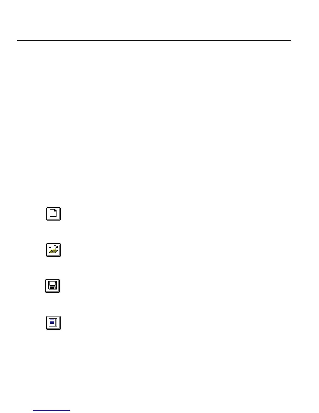
Tool bar
The tool bar, located under the menu bar near the top of the screen, makes it easy to perform some
often-used functions. Each function can be performed from a menu, however, using the tool bar is
much faster.
New file
Start a new configuration file with default values.
Open file
Open an existing configuration file.
Save file
Save the currently selected configuration file.
Server List
Display the list of Perle 833 remote access servers. Select a server to make a connection.
28 Perle 833 Remote Access Server Guide
Page 39
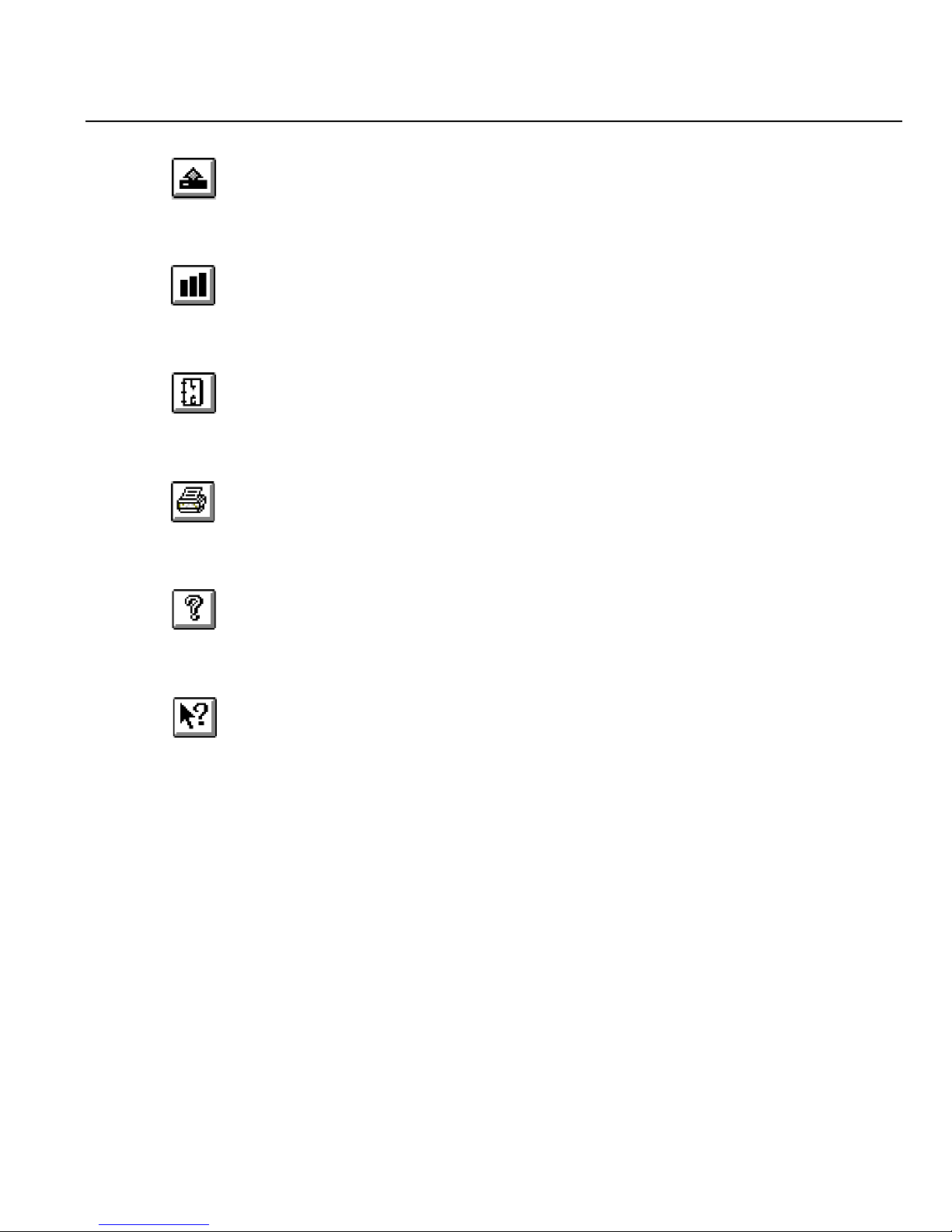
Chapter 3: Manager Software Installation and Setup
Get Configuration
Get the current configuration from the connected Perle 833.
Get Statistics
Get the Statistics data from the Perle 833 and display it in the System Statistics window.
Get Event Log
Get the event log from the Perle 833.
Print
Print the current configuration information.
About
Display the version number of Perle 833 Manager and a copyright notice.
Directed Help
Change the cursor to a question mark. Move the question mark over any screen item and click
to get help information on the item.
Perle 833 Remote Access Server Guide 29
Page 40

Manager Main Screen
30 Perle 833 Remote Access Server Guide
Page 41

Chapter 4: Server Configurations
This chapter describes how to set up a Perle 833. In this chapter you will read about:
• Configuration Overview
• Opening Configuration File
• Server Options
• Port Options
• User List Options
• Downloading a Configuration
Configuration Overview
The following steps describe the basic procedure to configure the Perle 833. The topics are then
discussed in more details in later sections.
1. Open a Configuration File.
This includes uploading a configuration from an attached Perle 833, opening an existing
configuration file on the Manager PC, or creating a new configuration file.
2. Edit the Perle 833 general parameters.
This includes options such as defining modem pools and giving the server a name.
3. Configure the Network Protocols.
Parameters for the protocols, IP and IPX, running on your network may need to be configured.
These parameters include IP addresses, MAC addresses, or IPX frame types.
4. Configure Security features.
Access to the network is controlled by the Perle 833 security features. A security method needs
to be selected and configured.
5. Edit the Perle 833 ports.
Configuring the ports usually involves setting the modem type, baud rate, and access.
Perle 833 Remote Access Server Guide 31
Page 42

Open Configuration File
6. Add / Edit user records.
Users are the people who will dial into the LAN through a Perle 833. Some of the things that
can be configured for each user are: name and department, password, call back options, filters
and connect time duration.
7. Save the file.
Note: Steps 1 through 7 (except for uploading a configuration) can be done without having a
Perle 833 connected to the PC.
8. Download the Configuration
This will copy the configuration file to the Perle 833 and set it in the server’s memory.
Open Configuration File
The configuration file contains a detailed set of configuration data for the Perle 833 including the
server’s name, network protocol parameters, serial port parameters and user records. Once a file has
been created, it can be used to set the configuration for one server or it can be saved and used as a
base for any number of servers. A configuration file can be opened for editing by following one of
the following procedures:
Create a New Configuration File
1. From the Manager File menu, select New.
2. The New Configuration dialog box appears. Select the appropriate Perle 833 server type. Click
OK.
3. The Configuration File window will appear with the default settings for the selected server type.
Open an Existing Configuration File
1. From the Manager File menu, select Open.
2. Select the required configuration file from the file list and click OK.
3. The Configuration File window appears with the setting of the selected configuration file.
32 Perle 833 Remote Access Server Guide
Page 43
Chapter 4: Server Configurations
Get a Perle 833 Current Configuration File
1. From the Manager File menu, select Device List.
2. The Server List window appears. Select the Perle 833 from which you want to get the
configuration file and click Connect.
3. The Log On dialog box appears. Enter a User ID and password. Click OK.
The User ID needs administrative privileges to make a connection with the Manager.
Note: The default administrative name for an unconfigured Perle 833 is:
superusr (with no password)
4. If the User ID and Password are verified, then the Manager Main screen with the Quick Button
window is displayed. Click the Get the current configuration from the server button. The
configuration file will be transferred from the selected server to the Manager PC.
5. The Configuration File window appears with the settings of the selected Perle 833.
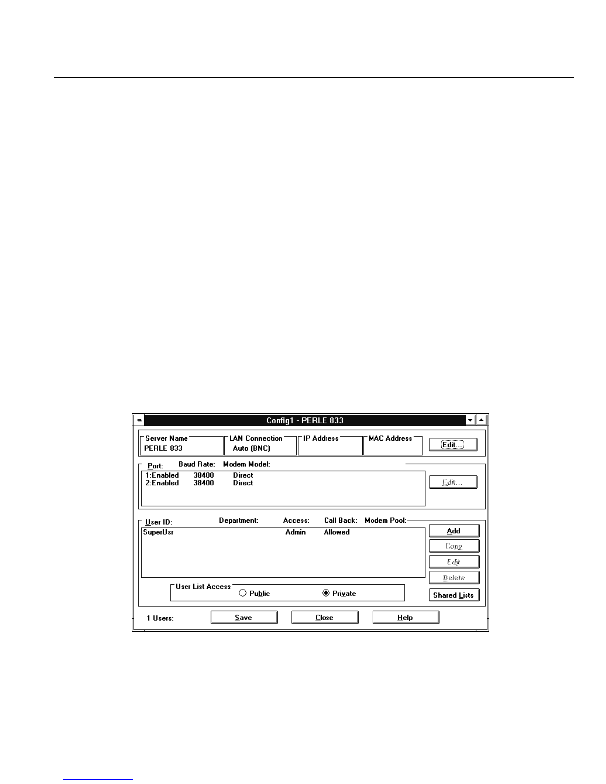
Configuration File Window
The Configuration File window is divided into sections which are described below.
Server
Port
User
Perle 833 Remote Access Server Guide 33
Page 44
Server Options
Server section
Use this section to configure the server itself, including such things as a server name, front panel,
filters, password, connection type, modem pools, IP, IPX and MAC addresses.
Port Section
Configure the serial ports of the Perle 833. This includes modem type, baud rate, dial-out parameters
and many other options.
User List Section
Use this section to Add or Edit User records in the User List. This includes user names, passwords,
filters, call back features, activity time-outs and privileges. Specify how the User List can be used
or found.
Server Options
Follow these steps to configure the server parameters.
1. Open the required configuration file.
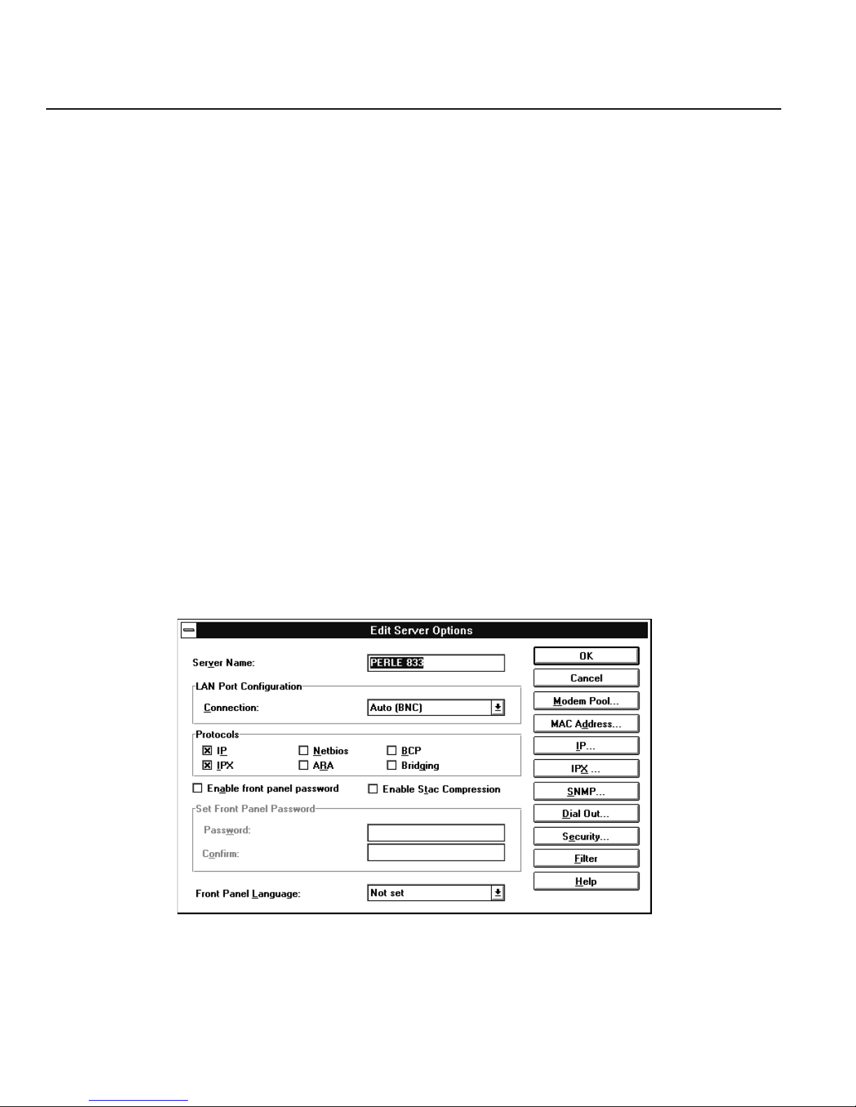
2. From the Server section of the Configuration File window, click Edit. The Edit Server Options
dialog box appears.
34 Perle 833 Remote Access Server Guide
Page 45

Chapter 4: Server Configurations
3. Give the server a name by typing it in the Server Name field.
The server name is used to identify the remote access server on the network. It is used by router
information protocols (RIP) and service advertising protocols (SAP). Make sure to use a name
that properly identifies the server you are naming.
4. From the LAN Port Configuration drop-down list, select a connection. The options depend on
the Perle 833 model:
Ethernet:
Select the type of connector that will be used to connect the Perle 833 to the network. The
choices are:
Auto (BNC) This is the default. This will automatically detect whether the BNC or
10Base-T (RJ-45) connector is being used.
Auto (AUI) This choice will automatically detect whether the AUI or 10Base-T
(RJ-45) connector is being used.
10Base-2 (BNC) The BNC connector will be used.
10Base-T The 10Base-T (RJ-45) connector will be used.
10Base-T (no test) The 10Base-T (RJ-45) connector will be used. The server will not test to
see if a connection has been made.
AUI The AUI connector will be used.
Token-Ring:
Select the correct token-ring speed for the network. The choices are 16 Mbps (default) or
4 Mbps.
5. Enable all protocols that the server needs to process. A protocol is enabled by clicking on its
checkbox. By default, only the IP and IPX protocols are enabled. The Bridging protocol is a
proprietary protocol used by the Perle 833 Dial-In Client (version 4.8 or earlier).
Please note the following:
•If the IP or IPX protocol is disabled, then any other configuration item that uses this
protocol will not be assessable.
• If a security feature that uses the IP or IPX protocol has already been configured, you will
not be allowed to disable the protocol.
Perle 833 Remote Access Server Guide 35
Page 46

Server Filter Assignment
6. If you want a password enabled for the front panel, click on the Enable Front Panel Password
check box and type a password of up to 8 digits long, using the digits 0-9 (no alpha characters
allowed).
7. If you wish to enable Stac (software) compression, click on the Enable Stac Compression check
box. Note that this compression is only useful in an environment where most calls are digital.
On analog calls this compression technique will actually create additional overhead since the
modems are already providing hardware compression of the data. The default is no Stac
compression.
8. The front panel language may be changed, if desired, by selecting another language from the
Front Panel Language drop-down list.
9. Configure the network protocol parameters that are required for your network and for the dialin clients being used for remote access. These parameters are accessed by clicking on the MAC
Address..., IP..., or IPX... buttons. See “Chapter 5: Configuring Network Protocols” on page
47 for a full description of the network parameters and how to configure them.
10. To configure Modem Pools or Dial-Out, see “Chapter 8: Dial-Out” on page 85.
11. To configure SNMP, see “Chapter 9: Network Administration” on page 93.
12. To assign Filters, see “Server Filter Assignment” below for more details.
13. To configure Security, see “Chapter 10: Security” on page 103. You should select the highest
level of security supported by your network.
14. Click OK to save your changes or Cancel to exit without saving.
Server Filter Assignment
Use this window to assign up to 10 IP and 10 IPX filters to the server. The server will process these
filters from the top down, so the order may be important. See “Packet Filtering” for more details on
how the filters are used.
To assign IP and/or IPX filters for the server, follow these steps:
1. Select a filter name from the Defined Filters pull-down list and click Add to add the filter to the
Assigned Filters list.
• You can change the order of the assigned filters by selecting a filter name from the
Assigned Filters list and clicking the Move Up or Move Down buttons.
36 Perle 833 Remote Access Server Guide
Page 47

Chapter 4: Server Configurations
• You can delete a filter assignment by selecting a filter name from the Assigned Filters list
and clicking the Remove button.
2. Set the Default Action to be taken if a packet does not match any assigned filter.The choices
are to Accept or Reject.
3. If you need to define more filters, then click the Define button in either the IP or the IPX section.
The IP Filter Definition or IPX Filter Definition dialog box appears.
4. Click OK to save your changes.
Setting the date and time
Setting the date and time on a Perle 833 is done separately from setting up the configuration file. The
Perle 833 must be connected to the PC running Perle 833 Manager. To set the date and time, follow
these steps:
1. From the Configure menu, select Set Date and Time.
2. In the dialog box that appears, set the appropriate date and time, and click OK.
The date and time are immediately changed in the attached Perle 833.
Serial Port Options
To configure the serial ports, follow these steps.
1. Select the port or ports you want to configure and click the Edit button.
Note: You can configure more than one port at a time by pressing Ctrl and clicking on more
than one port. Fields that are the same among the ports are displayed; fields that are
different among the selected ports are grayed out.
Perle 833 Remote Access Server Guide 37
Page 48
Serial Port Options
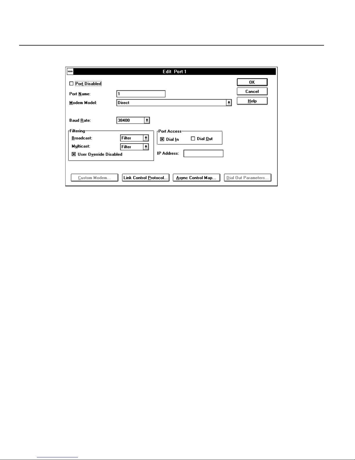
2. The Edit Port dialog box appears.
3. To disable the port, click on the Port Disabled check box.
4. You should give the port a meaningful name. The name will be used in the Perle 833 Dial-Out
software to identify ports that are available for dial-out. If the port name is left blank, the manager
software automatically assigns a numeric name to this field.
5. From the Modem Model drop-down list, select the make and name of your modem. If you can't
find your modem in the list, select the one that most closely resembles your modem.
6. Set the port baud rate from the drop-down list. This rate will be the fixed rate for Dial-In. This
means that Dial-In callers will always run at this speed.
Note: Since modems negotiate to a mutually agreed speed, callers with slower modems will
be able to connect. The parameters should be set to the highest speed at which the
attached modem can run on its serial port.
7. Enter a Dial Prefix string if required. This number will be added to the beginning of a phone
number in the following conditions:
• If the port is used for call back.
• If the port is used for Dial Out. The port must belong to a Modem pool that is configured
for Dial-Out and configured with an auto-dial phone number. If the dial out client
application is dialing the number, then the prefix will not be used. The field would be used
if a port was connected to a PBX line. The prefix can be up to 4 characters in length.
38 Perle 833 Remote Access Server Guide
Page 49

Chapter 4: Server Configurations
8. Optionally, enter an IP address for this port. The network portion of the address must be the
same as network portion of the server’s IP address. The IP address will be assigned to the client
who dials into this port.
9. The Filtering option can be used to either enable or disable the Perle 833’s ability to filter out
Broadcast and Multicast frames (both types or just one) from begin sent over the dial-in link to
the Perle Remote. The settings of these filters depend on the protocol used. For example, for
IPX, you would normally set Broadcast and Multicast to Filter. However, the NetBEUI
protocol or LLC protocol needs to have the Multicast set to Pass. As well some software
applications may require these message frames. See your network administrator for the correct
settings. To configure the filter feature:
a) Select Pass from the drop down lists if required for the Broadcast and Multicast fields.
b) The Perle Remote has the option to override the options set here in the Perle 833. If the User
Override Disabled field is checked, then the Perle Remote will not be able to use its override
function.
10. Set any other necessary parameters. These include:
• Dial-In/Dial-Out port access. A check means enabled. If neither is checked, then the port
can only be used for call back.
• Link Control Protocol parameters (see “Chapter 12: Custom Server Configuration” on
page 133).
Note: Most users will not need to change these parameters because this is an advanced
feature that affects very few users.
• Async Control Character Map (see “Chapter 12: Custom Server Configuration” on page
133).
Note: Most users will not need to change this parameter because this is an advanced feature
that affects very few users.
• Dial-Out parameters (see “Chapter 8: Dial-Out” on page 85).
11. Click OK.
Follow these same steps for any other ports that need to be configured.
Perle 833 Remote Access Server Guide 39
Page 50

User List Options
User List Options
User Records
To add or edit the user records, see “Configuring a User Record” on page 71.
User List Access.
The Perle 833 can be configured to share it's list of User records with other Perle 833 servers on the
LAN. This feature allows the administrator to store all user records in up to two servers instead of
storing a copy of the User List on every server on the LAN. To configure:
Select the access privilege for the User List configured on the Perle 833. The options are:
Public
The User List will be accessible to any remote Perle 833 on the LAN which has been configured
for Search Remote.
Private
The User List will be accessible only to users that connect to the local Perle 833. However, the
local Perle 833 can access the User Lists on other Perle 833 servers on the LAN if the local
server is configured for Search Remote
Shared User Lists.
Click the Shared Lists button to configure the Perle 833 to access the User Lists on other servers.
See “Shared User Lists” on page 74 for configuration instructions.
Save Configuration File
The configuration file should be stored on the Manager PC’s local drive for backup purposes. To
save the configuration file, follow one of the procedures below:
Save a New Configuration File
1. From the Manager File menu, select Save As.
2. Enter a file name for the new configuration and click OK.
3. The Manager will save the configuration in a new file with the specified name.
40 Perle 833 Remote Access Server Guide
Page 51
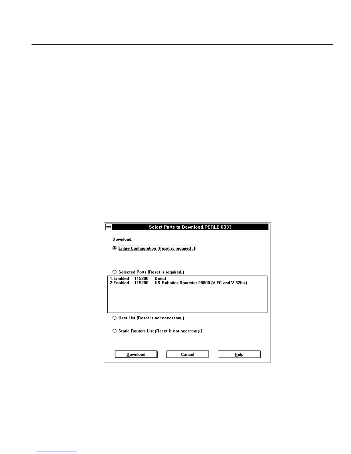
Save an Existing Configuration File
1. From the Manager File menu, select Save.
2. The Manager will save the changes to the configuration in the existing file.
Download the Configuration
The configuration file needs to be downloaded to a Perle 833 for the parameters to take effect. The
entire configuration can be downloaded or just certain sections such as user records or port
configuration. If only sections of the configuration are downloaded, the Perle 833 does not have to
be reset. The following steps describe how to download a configuration:
1. Make sure that the Manager PC is connected to the Perle 833 and that the appropriate
configuration file has been opened.
2. From the Configure menu, select Download Configuration.
Chapter 4: Server Configurations
3. The Download Configuration dialog box appears. Click the radio button beside one of the
following options:
Perle 833 Remote Access Server Guide 41
Page 52

Protocol Enable/Disable
Entire Configuration
The entire configuration file is downloaded and the Perle 833 must be reset before the
configuration changes take effect.
Selected Ports
Select one of the listed ports. Only the configuration for this port will be downloaded. The
port must be reset before the changes take effect.
User List
There is no reset required for this option. The changes will take effect the next time a new
or modified user tries to make a connection.
Static Router List
This will replace the existing list in the Perle 833 and will take effect immediately.
4. Click on the Download button. The Manager will download the selected portions of the
configuration file. If the download selection requires a reset of the server or serial port, the
Manager will ask for a confirmation of the reset.
Note: Any existing user sessions will be terminated when the Perle 833 is reset or a port is
reset
Protocol Enable/Disable
The IP, IPX, Netbios, ARA, BCP and bridging protocols can be turned off and on. At the Server
Level, the unit will prevent any connections with the disabled protocols and also will not use it for
its own purposes (i.e. security access).This feature will also be available at the User Level.
Event Log
The Event logging function has been improved to provide consistent andpertinent information. The
new or improved messages are:
Dial-in begin, Dial-in end
Call-back event ( including the call back number )
Dial-out begin, Dial-out end
The Dial-out number will be logged where it is known. If the number is provided by the application
(i.e. DUN), it will not be logged. The workstation address from where the dial-out initiated will be
logged.
42 Perle 833 Remote Access Server Guide
Page 53

Dialing prefix/port
This feature is useful in a callback environment. The user will be able to configure a dialing prefix
on a port basis. The prefix will be added to thebeginning of the phone number for dialing. This is
useful if you have some modems on PBX lines, and some that are not. This feature can also be used
for dial-out purposes but will only function when the 833 is dialing the number. If the application (
ex. DUN ) is dialing the number, the prefix will not be applied.
Packet Filtering
The Packet Filtering feature allows the Perle 833 Server to accept or reject incoming data packets
that match an entry on a list of defined filters. The filters are based on protocol, and packet addresses.
Up to 50 IP and 50 IPX filters can be defined with the following parameters:
• IP filters can specify Address, Mask, Sub-protocol, and port.
• IPX filters can specify Network, Node, Socket and Sub-protocol
After the filters have been defined, then up to 10 IP and 10 IPX filters can be assigned to the Perle
833 or to each user or to both.
Chapter 4: Server Configurations
Filters will be used by the Perle 833 Server in the following way:
1. The user record for the dial-in user will be checked. If the record has been configured to Disable
Server Filters, then only the user assigned filters will be checked. Proceed to point 4.
2. Incoming data packets are compared with the filters assigned to the server starting with the first
filter in the Server Filter Assignment list. As soon as the packet matches one of the filters, then
the packet is accepted or rejected and no further checking is done.
3. If the packet does not match any of the filters assigned to the server, then the user record will
be checked. If there are no user assigned filters, then the server default action will be carried out
to accept or reject the packet and no further checks are done.
4. The incoming data packet will be compared to the filters assigned to the user, starting with the
first filter in the User Filter Assignment list. As soon as the packet matches one of the filters,
then the packet will be accepted or rejected.
5. If the packet does not match any user assigned filters, then the user default action will be carried
out to accept or reject the packet.
Perle 833 Remote Access Server Guide 43
Page 54

Packet Filtering
To configure IP Filters:
1. From the server section of the configuration file window, click the Edit button. The Edit Server
Options dialog box that appears.
2. Click the IP button. The Edit IP Profile dialog box appears.
3. Click the Define Filters button. The IP Filter Definition dialog box appears.
To configure IPX Filters:
1. From the server section of the configuration file window, click the Edit button. The Edit Server
Options dialog box that appears.
2. Click the IPX button. The IPX Frames and Network Numbers dialog box appears.
3. Click the Define Filters button. The IPX Filter Definition dialog box appears
To assign filters to the Perle 833 server:
1. From the server section of the configuration file window, click the Edit button. The Edit Server
Options dialog box that appears.
2. Click the Filter button. The Server Filter Assignment dialog box appears.
To assign filters to a user:
1. From the users section of the configuration file window, click Add. The Add User dialog box
appears.
2. Click the Filter button. The User Filter Assignment dialog box appears.
Packet filtering works in conjunction with the RADIUS and Shared User List security systems.
Shared User List - Filters can be configured and assigned to a user record on the Remote Perle 833.
These records will be sent to the Local Perle 833 when a user dials in and makes a connection.
44 Perle 833 Remote Access Server Guide
Page 55

Chapter 4: Server Configurations
RADIUS – To use packet filtering with the Radius security server:
1. Define the filters on the Perle 833 Server.
2. Configure the user record on the Radius server with the names of the filters to be assigned to the
User.
3. When a user dials into the Perle 833, the name of the filters will be sent from the Radius server
to the Perle 833.
Perle 833 Remote Access Server Guide 45
Page 56

Packet Filtering
46 Perle 833 Remote Access Server Guide
Page 57

Chapter 5: Configuring Network Protocols
This chapter will provide information and configuration instructions on the network protocols
supported by the Perle 833.
In this chapter you will read about:
• IP parameters, configuration, filters and static routing
• IPX parameters, configuration, filters and static routing
• MAC Addressing
• AppleTalk protocol
•NetBEUI
IP Parameters
IP (Internet Protocol) Address
The IP address is a 4 byte number that uniquely identifies a host on the IP network. The IP
address consists of a network number, which is the same for every host on the subnet, and a host
number, which must be unique for each host on the subnet. The IP address is specified in dotted
decimal notation.
Subnet Mask
A subnet is a logical subsection of an IP network. The Subnet Mask indicates the network portion
of the IP address. Enter an IP network mask address in the Subnet Mask field if there is a specific
mask that your network requires.
Default Gateway
The Default Gateway is used to forward IP packets to IP hosts which are not on the local network.
BOOTP
The Perle 833 can retrieve an IP address for itself from a Bootstrap Protocol (BOOTP) server
located on the LAN. When the Perle 833 is first started up, a BOOTP request is sent every 3
seconds (up to 5 times). If a valid IP address is received, the Perle 833 uses it.
Perle 833 Remote Access Server Guide 47
Page 58

IP Parameters
RARP
The Perle 833 can retrieve an IP address from a Reverse Address Resolution Protocol (RARP)
server. On start-up a RARP request is sent every 3 seconds (up to 5 times). If a valid response
is received, then the IP address is used.
IP Requirements
This section discusses the requirements to run the Perle 833 on an IP network.
1. IP address for the Perle 833. This address will be obtained using the following ways. The Perle
833 will try each of these methods in the order they are described until a valid address is found.
a) Acquire an IP address from a BOOTP server.
b) Acquire an IP address from an RARP server.
c) Use the configured IP address.
2. Subnet Mask.
3. Default Gateway address.
4. IP address for any routing based dial-in clients. This address can be configured in the following
ways. The Perle 833 will look at each of these methods in the order they are described until a
valid address is found.
a) Client specifies an IP address at connect time.
b) The user record has been configured with an IP address.
c) The serial port to which the client is connecting has been configured with an IP address.
d) The Perle 833 has been configured with an IP address pool.
e) The Dynamic Host Configuration Protocol (DHCP) server supplies the IP address.
Note: The Perle Remote does not need an IP address. It uses only MAC addressing for
directing data packets. However, since users may be running IP applications on a PC
running the Perle Remote, they will still need an IP address. The address in this case
will need to be configured on the PC.
48 Perle 833 Remote Access Server Guide
Page 59
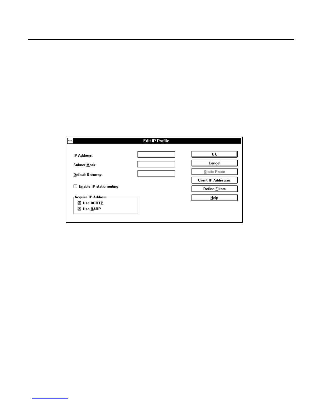
Chapter 5: Configuring Network Protocols
Configuring IP Parameters
To configure IP parameters, follow these steps.
1. If you are to use a BOOTP or RARP server on your network for IP address acquisition, then
install and set up this server.
2. From the Server section of the Configuration File window, click Edit.
3. From the Edit Server Options dialog box, click on the IP button.
4. The Edit IP Profile dialog box appears
5. Locate your cursor in the IP Address field and edit the number. The subnet mask number is
automatically generated following the standard network class rules. You should only change
this if your network has special requirements.
6. Enter an IP address for a Default Gateway if your network is equipped with a Gateway.
7. The Perle 833 will search for an IP address in both a BOOTP and RARP server by default. If
you do not have one of these servers on your network, then clear the check boxes beside the
appropriate server field.
8. To define filters, click the Define Filters button. See “IP Filter Defintion” on page for more
details.
9. To configure IP addresses for dial-in Client users, click the Client IP Addresses button and
enter the required data. See “Client IP Addresses” on page 50.
Perle 833 Remote Access Server Guide 49
Page 60
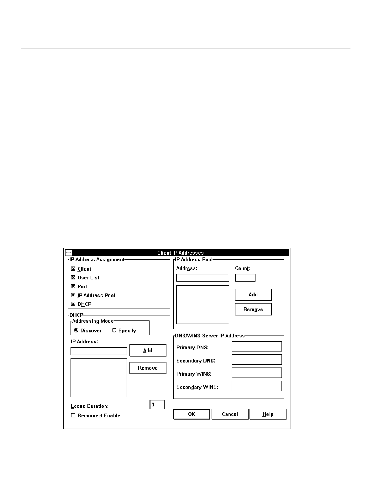
IP Parameters
10. Click OK in the Client IP Address dialog box, and click OK in each subsequent dialog box
until the Configuration File window is visible again.
11. The Perle 833 allows you to se up a unique IP address for each user. The address is configured
in the user records. If you want to specify an IP address for a user, see “Chapter 6: User Records”
on page 71.
12. The Perle 833 allows you to set up a unique IP address for each port on the Perle 833. If you
want to specify an IP address for a serial port, see “Serial Port Options” on page 37.
Client IP Addresses
An IP address is required for any user that dials into a IP network through the Perle 833 using a
routing client such as Windows 95 and Windows NT.
To configure Client IP Addresses:
1. From the Server section of the Configuration File window, choose Edit. In the Edit Server
Options dialog box that appears, click on the IP button. The Edit IP Profile dialog box appears.
2. Click on the Client IP Address button. The Client IP Address dialog box appears.
50 Perle 833 Remote Access Server Guide
Page 61

Chapter 5: Configuring Network Protocols
3. In the IP Address Assignment area, check one or more of the following checkboxes to specify
how the dial-in client is assigned an IP address. The server will use all selected methods in the
order they are listed below. The search will stop when a valid address is found.
a) Client - Dial-in client provides his own address. This address is entered when the dial-in
client is configured.
b) User List - The Perle 833 server's user list can be configured to have an IP address for each
user. If you want to specifiy an IP address for each user, see “Configuring a User Record”
on page 71.
c) Port - Each of the dial-in ports can be configured to have an IP address. See “Serial Port
Options” on page 37.
d) IP Address Pool - A pool of addresses can be defined on the server. An address is selected
from that pool and relayed on to the client.
e) DHCP - Upon client connection the DHCP server is contacted and an IP address is obtained.
Except for the Client option, the Perle 833 will pass the IP address to the Client software when
a user dials in and makes a connection.
4. IP Address Pool
If the IP Address Pool option has been selected in the IP Address Assignment section, then the
IP Address Pool configuration section is enabled. A pool of IP addresses can be created and the
first available address will be assigned to a dial-in client when a connection is made. The number
of addresses in the pool can be as high as the number of serial ports on the Perle 833 being
configured.
Adding IP address(es) to the Pool
a) Enter an IP address in the Address field.
b) Optionally enter a value in the Count field.
c) Click the Add buuton.
d) The address or range of address will be displayed in the IP Address Pool list.
Removing an IP Address from the Pool
a) Select the IP address from the IP Address Pool list.
b) Click the Remove button.
c) The address will be deleted from the IP Address Pool list.
Perle 833 Remote Access Server Guide 51
Page 62

IP Parameters
5. DHCP
DHCP (Dynamic Host Configuration Protocol) permits the management of IP addresses (and
other IP related options) from a single location. DHCP Servers are used to assign addresses to
Hosts (PC's) that do not require a fixed or static IP address. Upon connection the Perle 833 will
obtain a IP address lease from the DHCP server and relay the address on to the client. The Perle
833 will maintain and renew the lease as necessary. The DHCP server will also return Primary
and Secondary DNS (Domain Name Server) IP addresses as well as Primary and Secondary
WINS (Windows Internet Name Server) IP Addresses. WINS is also sometimes referred to as
NetBios Name Server. If the client is configured to accept these parameters from the Perle 833
these will be passed on to the client.
If the DHCP option has been selected in the IP Address Assignment section, then the DHCP
configuration section is enabled. Select or enter the following data as required.
Address Mode
1) Select Discover to allow the Perle 833 to find any DHCP server on the local network with
an available address.
2) Select Specify to configure the IP addresses of the DHCP servers. Up to four DHCP server
addresses can be configured. If one is not responding or does not have any IP addresses
available the next one will be tried.
Adding a DHCP IP address
a) Enter an IP address in the IP Address field.
b) Click the Add button.
c) The address will be displayed in the IP Address list.
Removing a DHCP IP Address
a) Select the IP address from the IP Address list.
b) Click the Remove button.
c) The address will be deleted from the IP Address list.
Lease Duration
This field specifies the length of time that the DHCP server will allow the Perle 833 to use the
IP address on behalf of the client. The range is 1 to 99 hours. The default is 3 hours. Longer
lease time will increase the chances that a client can reconnect to the Perle 833 and get the same
IP address.
52 Perle 833 Remote Access Server Guide
Page 63
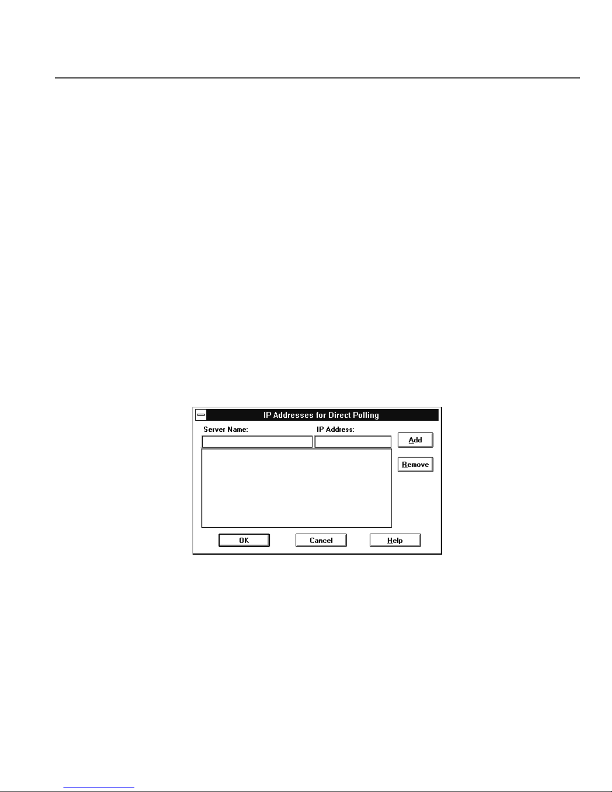
Chapter 5: Configuring Network Protocols
Reconnect Enable
Click on this check box to allow a dial-in user to disconnect and then reconnect at a later time
and retain the same IP Address.
Note: If the lease on the IP address has expired, then another user may have been assigned
that address.
Note: This feature requires that all dial-in users have a unique User ID.
6. DNS/WINS Server IP Address
For networks that do not have DHCP server, a Primary and Secondary DNS and WINS server
IP address can be configured in the Perle 833 server. The address will be passed to the dial-in
client when a connection is made.
Addresses for Direct Polling
When IP routers are configured not to route IP broadcast messages, the manager is unable to detect
the presence of any Perle 833 servers that are not on the local LAN segment.
The Direct IP Address Polling feature enables the user to configure the IP addresses of the servers
that are on remote LAN segments. The manager can poll these addresses directly so that the servers
can be found.
To add Perle 833 IP addresses to the polling list:
1. Enter the Perle 833 server's name in the Server Name field. The name consists of up to 15 alpha-
numeric characters.
2. Enter the IP Address for the server in dotted decimal notation.
Perle 833 Remote Access Server Guide 53
Page 64

IP Parameters
3. Click the Add button. The entry will be added to the list. The list is sorted alphabetically
4. Click OK. The list of addresses will be stored on the Manager PC's hard disk in a file called
5. The Server List dialog box will re-appear. The Manager program will now send messages
6. See “Server List” on page 20 for instructions on how to make a connection to a server.
To remove IP addresses from the polling list:
1. Select the entries in the IP Address list that you want to remove. The Ctrl and Shift keys can
according to the Server Names.
remhosts.ini.
directly to the addresses contained in the IP address list.If a response is received then the entries
in the Server List will be enabled.
• If no response is received, then the entry in the Server List will be disabled and the Model
field will be filled with asterisks (*****).
be used to select multiple entries.
2. Click the Remove button. The entries will be removed from the list.
3. Click OK to save the new list to the remhosts.ini file.
remhosts.ini File
This file contains the list of IP addresses for Direct Polling. It is located in the installation
directory for the Perle 833 Manager program (default is C:\perle833). It is read and written to
be the IP Address for Direct Polling dialog box.
Each entry is kept on an individual line. The server name starts in the first column followed by
the IP address. If the server name contains any spaces, then the entire server name will be
enclosed in quotes. The server name and the IP address will be separated by at least one space
or tab character.
54 Perle 833 Remote Access Server Guide
Page 65

Chapter 5: Configuring Network Protocols
IP Static Routing
The Perle 833 has room for 100 entries in its IP Routing Information Protocol (RIP) table. In some
large networks, there are more than 100 servers. As a result, some of the RIP table entries will be
overwritten and some of the routes will be unavailable.
Static routing lets the network administrator configure the Perle 833 with only the server address
routes that are required. Dynamic routing is disabled and the routing table will not change.
Note: The Perle 833 Manager when used with an in-band connection will broadcast a message
to find all Perle 833s on the network. If Static Routing is enabled for a Perle 833, then a
static route to the Manager’s network will need to be configured. This is required for the
Perle 833 to respond to the Manager’s broadcast message.
Configuring IP Static Routing
1. From the Server section of the Configuration File window, click the Edit button.
2. From the Edit Server Options dialog box, click on the IP button.
3. In the Edit IP Profile dialog box, click the Enable IP static routing check box.
Note: Dynamic routing will be disabled. If new servers are added to the network, then the
routing for these will need to be added to the static routing table.
Perle 833 Remote Access Server Guide 55
Page 66
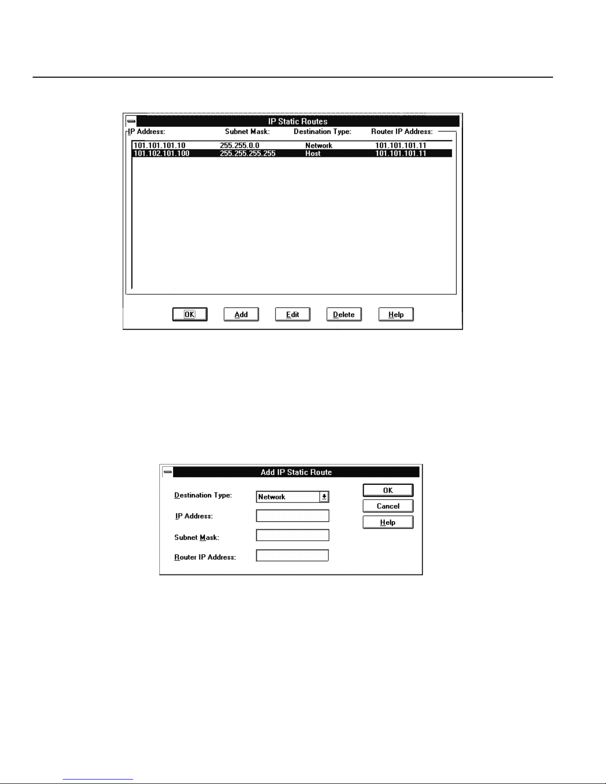
IP Parameters
4. Click on Static Route button. The IP Static Routes dialog box appears.
A list of all IP static routes currently configured are displayed. You can Add a new entry, or
Edit or Delete an existing highlighted entry.
5. To configure a new static route, click the Add button.
6. To edit an existing entry, select an entry from the table and click the Edit button.
7. The Add or Edit Static Route dialog box appears. Enter the following parameters.
Destination Type
The IP destination type. If the destination type is Host, the Subnet Mask is not userselectable.
IP Address
The IP address for the destination server.
56 Perle 833 Remote Access Server Guide
Page 67

Subnet Mask
The IP subnet mask for the destination. If the Destination Type is Host, this value is not
user-selectable.
Router IP Address
The IP address of the router used to send packets to the destination.
8. Click OK to return to the IP Static Route dialog box.
9. Click OK in the IP Static Route dialog box to save the static route entries.
IP Filter Definition
Use this window to create and manage the list of up to 50 filters for the IP protocol. IP filters can
specify the Address, Mask, Sub-Protocol and Port of the IP packet. The filters can accept or reject
incoming packets based on source and destination addresses.
To add a filter definition:
Chapter 5: Configuring Network Protocols
1. Click the Add button.
2. The Add IP Filter Definition window will appear.
To edit a filter definition:
1. Select a filter from the list.
2. Click the Edit button.
3. The Edit IP Filter Definition window will appear.
To delete a filter definition:
1. Select a filter from the list.
2. Click the Delete button.
3. The filter definition will be deleted.
Perle 833 Remote Access Server Guide 57
Page 68

IP Filter Definition
Add / Edit IP Filter Definition
To complete or modify the filter definition, enter the information in the following fields:
Name
The filter name can be up to 8 characters in length. You will use the name to assign filters to the
server or user. The name can also be used when adding filters to a user record on a RADIUS security
server.
Filter Action
Select whether to Accept or Reject incoming IP packets if the packet matches all parameters defined
in this filter. The default setting is Reject.
Source Address
This field is the IP address of the station that is sending the IP packet. The address should be entered
in dotted decimal notation.
Source Mask
This feature masks off both the filter source address and the packet source address by using the
Boolean AND function. If the two results are equal, then the address matches.
Destination Address
This field is the IP address of the station to which the IP packet is being sent. The address should be
entered in dotted decimal notation.
Destination Mask
This feature masks off the filter destination address and the packet destination address by using the
Boolean AND function. If the two results are equal, then the address matches.
Protocol
The entries are TCP, UDP, ICMP, and Other.
• If you select TCP or UDP, the Port Number section appears. Enter the Source and
Destination in the corresponding fields.
• If you select Other, make an entry in the Protocol field.
Once you have entered the correct information, click OK to save your changes.
58 Perle 833 Remote Access Server Guide
Page 69

IPX Parameters
Auto
The Auto setting will automatically determine the IPX framing type on the network. When the
Perle 833 is powered up, it sends a message encoded in each frame type and waits for a response.
It detects only the first framing type found. If your network has multiple frame types, you need
to manually enable each type.
Specify Manually (802.2; 802.3; SNAP; Ethernet II)
Manual specification is useful for a multiple frame environment.
Dial-In Network
Dial-In Network is an IPX network to which all remote Dial-In IPX clients are connected. The
Perle 833 appears as the IPX router with the LAN attached to one side and all of the Dial-In
clients attached to the other side.
Chapter 5: Configuring Network Protocols
IPX Requirements
This section discusses the requirements to run the Perle 833 on an IPX network.
1. IPX network number and frame type for the server. This information is usually determined
automatically by the Perle 833.
2. IPX number for dial-in clients. The Perle 833 can determine this automatically.
Note: The Perle Remote does not need an IPX network number if it is using the NetBUEI/
LLC protocol. It uses MAC addressing for directing data packets.
Configuring IPX Parameters
To configure IPX parameters, follow these steps.
1. From the Server section of the Configuration File window, click the Edit button.
2. From the Edit Server Options dialog box, click the IPX button.
Perle 833 Remote Access Server Guide 59
Page 70
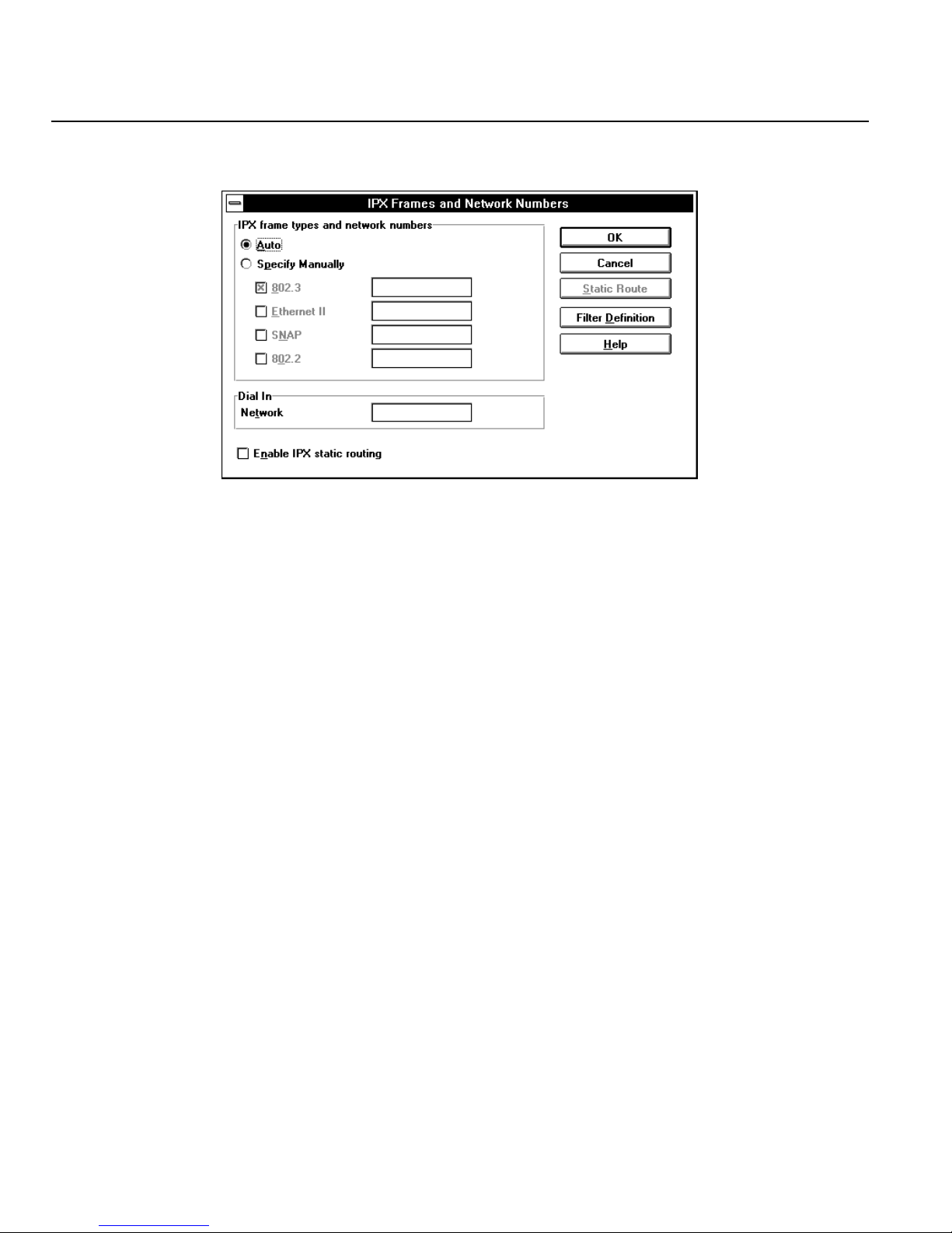
IPX Parameters
3. The IPX Frames and Network Numbers dialog box appears.
4. Click the Auto radio button to let the Perle 833 determine the frame type and network numbers
it needs to route IPX frames.
or
Click on Specify Manually if you want to control the frame types to be enabled. Frame types
that are unavailable appear grayed-out and cannot be selected.
• Click the check box next to each frame type you want to enable for this Perle 833. Leave
the address field blank to have the server supply a network address.
• If you type a fixed NetWare IPX network address, the Perle 833 will not update network
numbers to resolve conflicts for that frame type. The address field contains up to 8
hexadecimal digits. Do not enter FFFFFFFF or 0, as these addresses are reserved.
5. The Perle 833 will by default determine a suitable network number for the Dial-In connections.
If your network application requires you to set a fixed value, then enter this value in the Dial-In
Network field.
60 Perle 833 Remote Access Server Guide
Page 71

IPX Static Routes
The Perle 833 has room for 100 entries in its IPX Routing Information Protocol (RIP) table. In some
large networks, there are more than 100 servers. As a result, some of the RIP table entries will be
overwritten and some of the routes will be unavailable.
Static routing lets the network administrator configure the Perle 833 with only the server address
routes that are required. Dynamic routing is disabled and the routing table will not be changed.
Note: The Perle 833 Manager when used with an in-band connection will broadcast a message
to find all Perle 833s on the network. If Static Routing is enabled for a Perle 833, then a
static route to the Manager’s network will need to be configured. This is required for the
Perle 833 to respond to the Manager’s broadcast message.
IPX Network Services
The Perle 833 also keeps a 100 entry Service Advertising Protocol (SAP) table. This table will
contain a list of IPX network service programs and their locations within the IPX network. When
IPX Static Routing is enabled, SAP entries need to be made for each network service available at
each of the IPX static routings.
Chapter 5: Configuring Network Protocols
Configuring IPX Static Routing
1. From the Server section of the Configuration File window, click the Edit button.
2. From the Edit Server Options dialog box, click on the IPX button.
3. On the IPX Frames and Network Numbers dialog box, click the Enable IPX Static Routing
check box. The option for IPX frame types and network numbers will change to Specifying
Manually. Select at least one frame type, and enter a network number for each frame type you
select. Static routing cannot automatically determine network numbers.
Note: Dynamic routing will be disabled. If new servers are added to the network, then the
routing for these will need to be added to the static routing table.
Perle 833 Remote Access Server Guide 61
Page 72
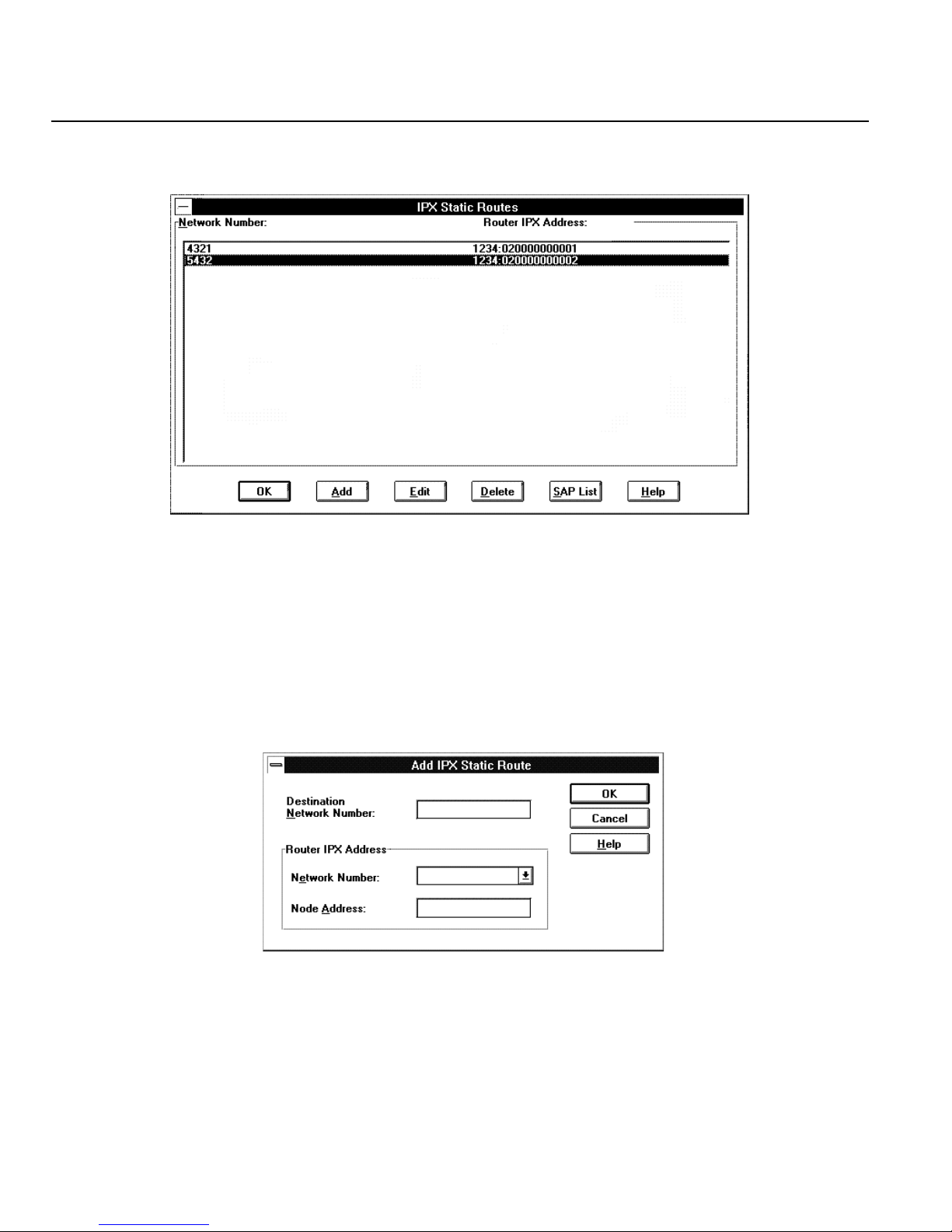
IPX Static Routes
4. Click on the Static Route button. The IPX Static Routes dialog box appears.
A list of all the IPX static routes currently configured are displayed. You can Add a new entry
or Edit or Delete an existing highlighted entry. For each IPX static route, a list of IPX services
that are available at the IPX destination can be created.
5. To configure a new static route, click the Add button.
6. To edit an existing entry, select an entry from the table and click the Edit button.
7. The Add or Edit IPX Static Route dialog box appears. Enter the following parameters.
Destination Network Number
The IPX network number for the destination. This can be up to 8 digit hexadecimal numbers.
62 Perle 833 Remote Access Server Guide
Page 73
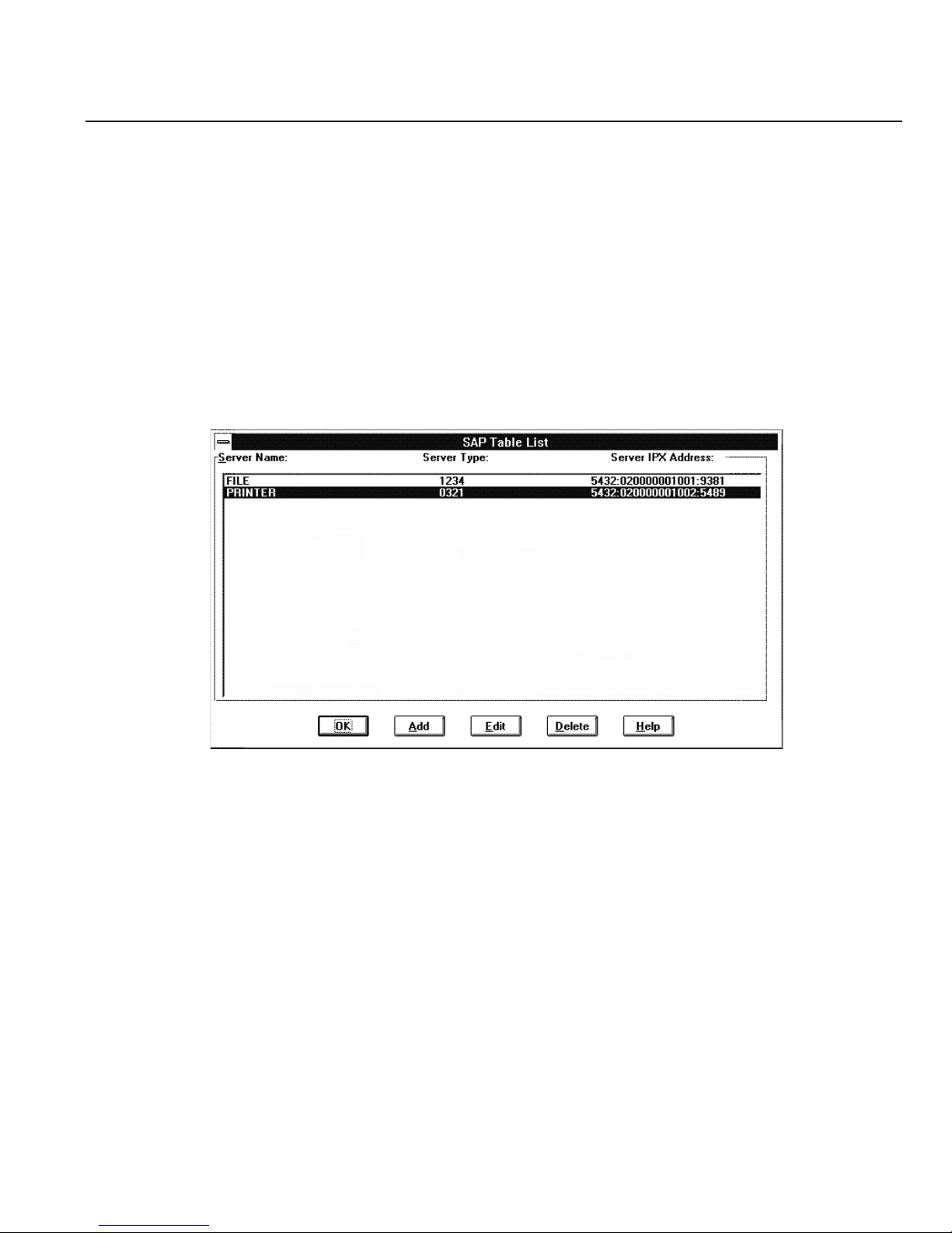
Chapter 5: Configuring Network Protocols
Network Number
The IPX network number for the router on the local LAN. Only those network numbers that
you have already given to frame types are listed.
Node Address
The IPX node address of the router on the local LAN. This is a 12 digit hexadecimal number.
8. Click OK to save the entry and return to the IPX Static Route dialog box.
9. To configure SAP entries for an IPX static route, select an IPX static route entry and click the
SAP List button. The SAP Table List dialog box appears.
A list of all the SAP table entries currently configured for the selected IPX static route are
displayed. You can Add a new entry or Edit or Delete an existing highlighted entry.
10. To configure a new SAP entry, click the Add button.
11. To edit an existing entry, select an entry from the table and click the Edit button.
Perle 833 Remote Access Server Guide 63
Page 74
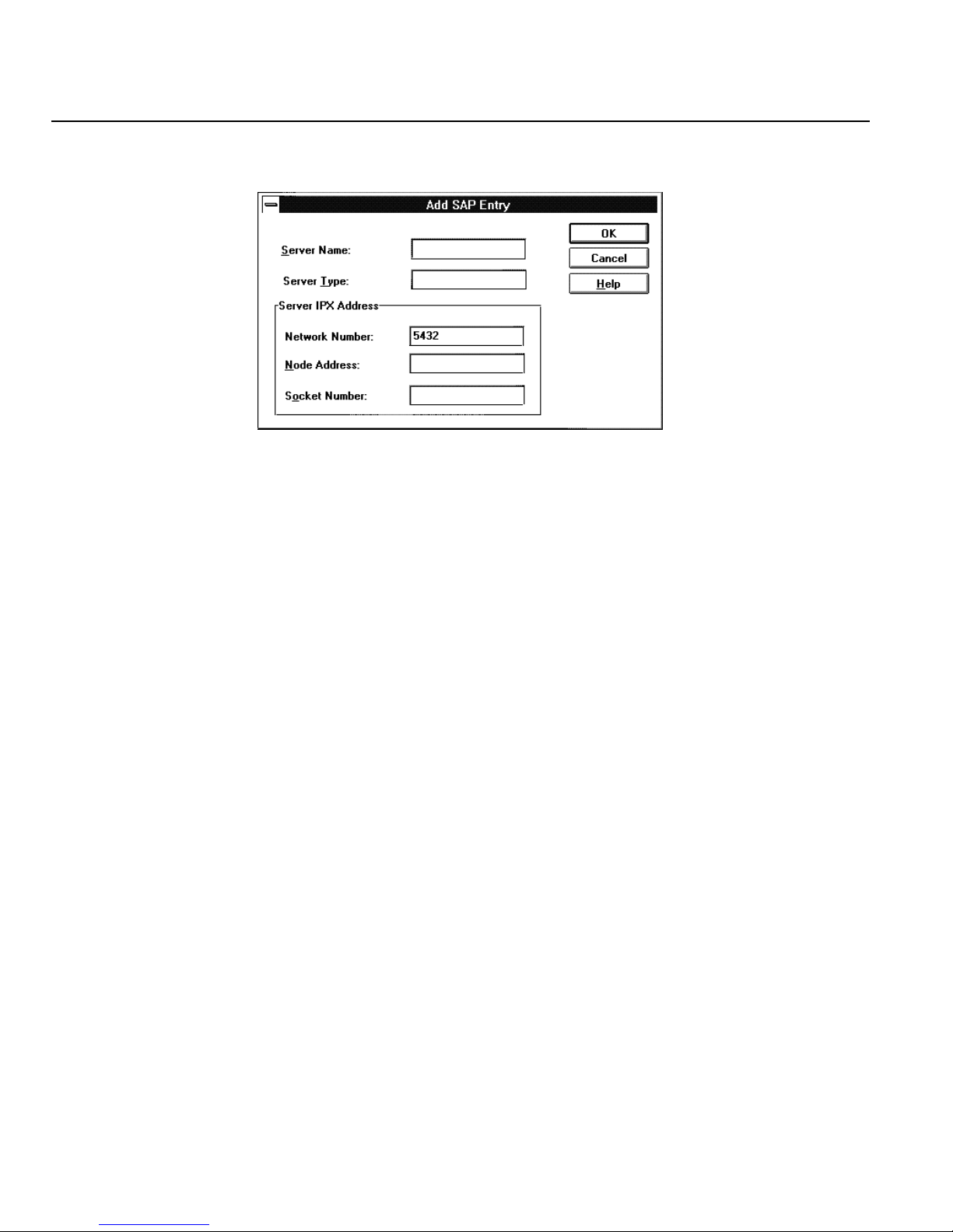
IPX Static Routes
12. The Add or Edit SAP Entry dialog box appears. Enter the following parameters.
Server Name
Server Type
The server name of the IPX static route destination. The name can be up to 48 characters
long.
The server type of the IPX static route destination. This is a 4 digit hexadecimal number.
Network Number
The IPX static route table network number for the destination that you have already entered.
Not user-selectable in this dialog box.
Node Address
IPX node address for the destination. This is a 12 digit hexadecimal number.
Socket Number
IPX socket number for the destination. This is a 4 digit hexadecimal number.
13. Click OK to save the entry and return to the SAP table list.
64 Perle 833 Remote Access Server Guide
Page 75

MAC addresses
This section will be of concern to you if you use the Perle Remote with the NetBEUI/LLC protocol.
Media Access Code (MAC) addresses represent the physical address of a network. When the Perle
Remote is used with the NetBEUI/LLC protocol, these address are used to send and recieve
messages to the LAN services.
Each Perle 833 model has several MAC addresses for communication on the LAN. One MAC
address is assigned to the Perle 833 itself, and one MAC address is assigned to each serial port. A
two-port server requires a minimum of three addresses, and an eight-port server requires a minimum
of nine addresses. These address have default values when the server is shipped from the factory.
These should not need to be changed.
If fixed MAC addresses are assigned to any users, then these default values have to be modified.
MAC addresses and Perle 833
A Perle 833's MAC addresses are set at the factory to unique values. If you need to change from the
default MAC addresses, you can use address values that end in 00 in the range of 020000000000 to
02FFFFFFFF00 (for Ethernet) and 400000000000 to 40FFFFFFFF00 (for Token Ring).
Chapter 5: Configuring Network Protocols
Fixed MAC Addresses
The Perle Remote software when running with the NetBEUI/LLC protocol needs to have a MAC
address to communicate properly with the LAN services. Some applications need to know this
address when the Perle Remote PC is powered up. As well some applications ( i.e. AS/400 Client
Access) required a dial-in user to have the same MAC Address each time they dial-in to the network.
These conditions are satisfied by configuring a fixed MAC address for each user on the Perle 833 in
the user profile. The user would then configure the Perle Remote with this same fixed address.
To configure fixed MAC address on the Perle 833, you must change the base modem port address
to a user defined value. You must also indicate the maximum number of fixed MAC address users
allowed in the network.
Note: The Perle 833 will respond to all addresses in the range selected (base address plus num-
ber of modem ports plus number of fixed MAC address users).The number of fixed MAC
address users in no way limits the total number of users.
Perle 833 Remote Access Server Guide 65
Page 76
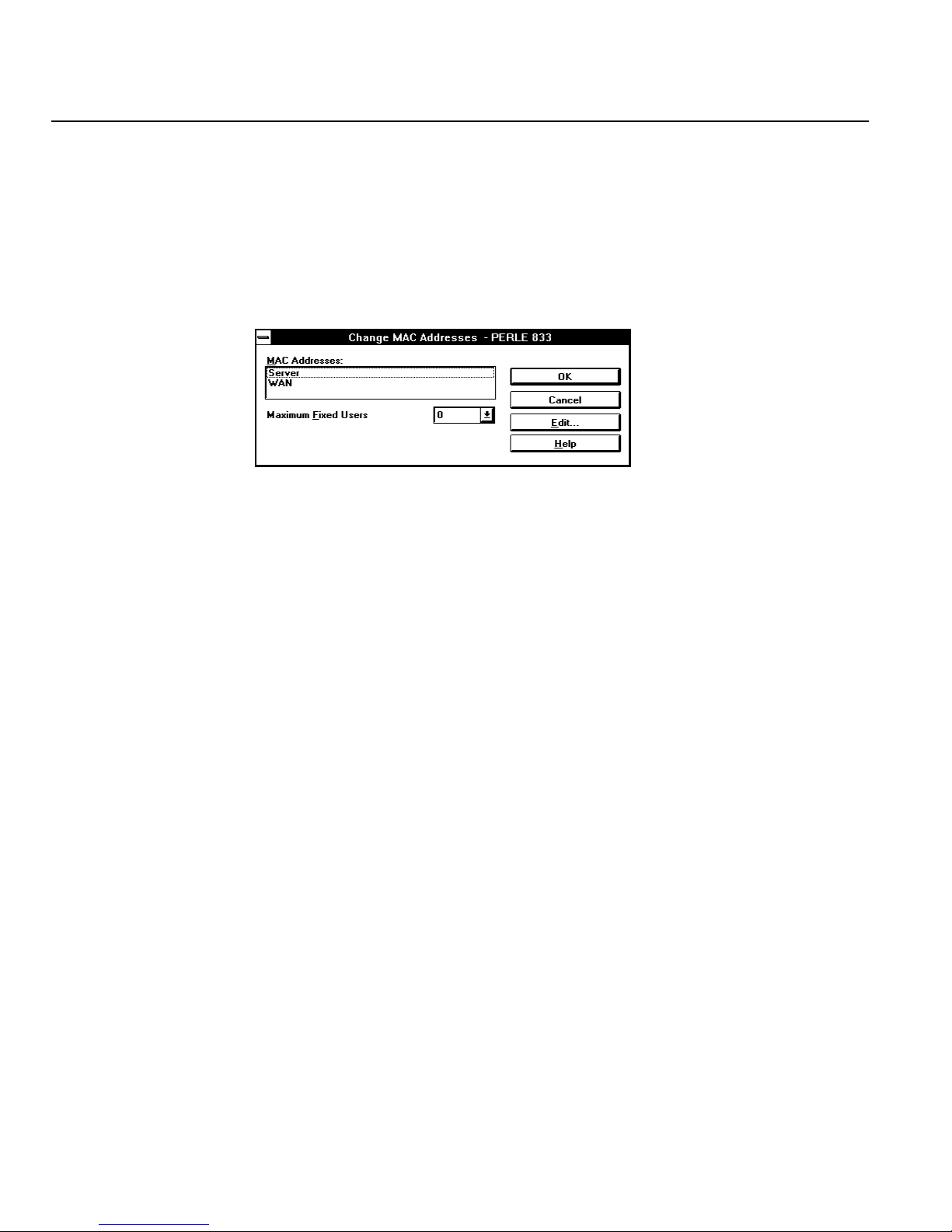
MAC addresses
To configure fixed MAC addresses, follow these steps:
1. From the Server section of the Configuration File window, click the Edit button.
a) From the Edit Server Options dialog box, click on the MAC Addresses button.
b) A dialog box appears displaying the MAC address of the connected Perle 833, and
2. Select the WAN MAC address and click the Edit button.
3. In the dialog box that appears, type in the new 12-digit hexadecimal MAC address, and click OK.
the base asynchronous WAN (serial ports) MAC address.
Make sure you comply with the numbering restrictions which were described above.
Note: When the WAN base address is modified, then the MAC address for a specific serial
port is found be adding the port number to the base address and subtracting 1.
Base Address Port 5 Address
020012345600 020012345604
4. Set the number of fixed address users to the closest value equal to or greater than the actual
number of fixed address users required in the network.
5. Click OK in the Change MAC Addresses dialog box, and click OK in each subsequent dialog
box until the Configuration File window is visible again.
6. To set the fixed MAC address for each user, see “Chapter 6: User Records” on page 71. The
address will be automatically assigned to each user from the MAC address pool.
66 Perle 833 Remote Access Server Guide
Page 77

IPX Filter Definition
Use this window to create and manage the list of up to 50 filters for the IPX protocol. IPX filters can
specify the Network, Node, Socket and Sub-Protocol. The filters can accept or reject incoming
packets based on source and destination network and node addresses and socket numbers.
To add a filter definition:
1. Click the Add button.
2. The Add IPX FIlter Definition window will appear.
To edit a filter definition:
1. Select a filter from the list.
2. Click the Edit button.
Chapter 5: Configuring Network Protocols
3. The Edit IPX Filter Definition window will appear.
To delete a filter definition:
1. Select a filter from the list.
2. Click the Delete button.
3. The filter definition will be deleted.
Add / Edit IPX Filter Definition
To complete or modify the filter definition, enter the information in the following fields:
Name
The filter name can be up to 8 characters in length. You will use the name to assign filters to the
server or user. The name can be used when adding filters to a user record on a RADIUS security
server.
Filter Action
Select whether to Accept or Reject incoming IPX packets if the packet matches all parameters
Perle 833 Remote Access Server Guide 67
Page 78

IPX Filter Definition
defined in this filter. The default setting is Reject.
Source Network Address
The address of the network that contains the station that is sending the IPX packet. It can be up to 8
characters long.
Source Node Address
Enter the node address of the station that is sending the IPX packet. It consists of 12 hexadecimal
characters.
Source Socket Number
The socket number on the station that is sending the IPX packet. The socket number can be up to 4
hexidecimal characters.
Destination Network Address
The address of the IPX network that the IPX packet is being sent to.
Destination Node Address
The node address that the IPX packet is being sent to.
Destination Socket Number
The socket number that the IPX packet is being sent to.
Packet Type
The entries are RIP, SAP, SPX, NCP, and Other.
• If you select Other, make an entry in the Type field. The field can be up to 3 numeric
characters.
Once you have entered the correct information, click OK to save your changes.
68 Perle 833 Remote Access Server Guide
Page 79

AppleTalk Protocol
The Perle 833 has built-in support for the AppleTalk Network protocol. This allows an Apple
Remote Access (ARA) client running on a Macintosh to dial-in to the server and access the
AppleTalk network.
The AppleTalk protocol is always available in the Perle 833 and no special configuration is required.
For more information, see “Using Apple Remote Access” on page 84.
NetBEUI
The Perle 833 supports the NetBios Extended User Interface (NetBEUI) protocol. This permits third
party clients (Windows 95 and Windows NT) to be used in a NetBios environment.
There is no configuration required to use this feature.
Note: The Perle 833 supports up to 10 sessions per connection using NetBios. The maximum
sessions in the client NetBEUI configuration must be set to a value of 10 or lower.
Chapter 5: Configuring Network Protocols
Perle 833 Remote Access Server Guide 69
Page 80

NetBEUI
70 Perle 833 Remote Access Server Guide
Page 81

Chapter 6: User Records
This chapter describes the uses and configuration steps for the Perle 833 user records. In this chapter
you will read about:
• Overview of the User Records
• Adding or editing Users
• Shared User Lists
• Call Back Options
Overview
The Perle 833 can be configured with a set of user records (known as the User List) which contain
profile information about users of the server. These records have the following purposes.
• The records are used for password authentication if the Perle 833 has been configured for User
List security. See “Chapter 10: Security” on page 103 for more details.
• The records provide information on Call Back options and inactivity time outs for both User
List and some third party security services.
• At least one user record with administrative privileges must be entered for each Perle 833. This
allows access by the manager program for configuration or monitoring purposes.
The User List can be configured with 256 users. Each user can be configured with up to 5 call back
numbers or a maximum of 512. (Average of 2 call back numbers per user).
Configuring a User Record
New user records can be added, existing records can be edited, copied or deleted. To perform any of
these configuration functions, follow these steps:
1. Select or open the proper configuration file as described on page 32.
2. From the Users section of the Configuration File window, you can:
a) Click the Add button to add a new user.
b) Select an existing user record and click the Edit button to change the user’s information.
Perle 833 Remote Access Server Guide 71
Page 82
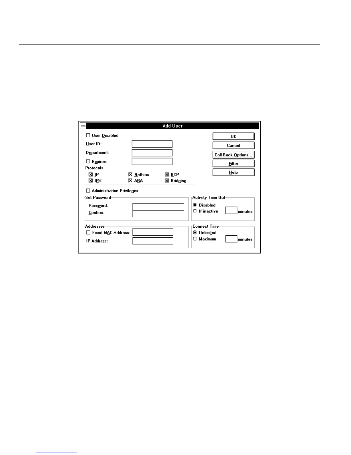
Configuring a User Record
c) Select an existing record and click the Copy button. This will create a new user record and
copy most of the information from the existing record.
d) Select an existing record and click the Delete button to remove the user record from the
configuration file. Click OK to confirm the deletion.
3. The Add User or Edit User dialog box will appear (except after deleting a record). Enter the
following parameters as required.
User Disabled
A user record is enabled by default. If you want to prevent a user from using the Perle 833
but want to keep the record in the configuration file, then click on the check box.
User ID
Enter the name of the user. This field is up to 8 characters long. The name is used in
combination with the password for log on authorization for User List security.
Department
The department name is for information purposes only. It is not used for granting privileges
or access.
Expires
This option will disable user records on a specific date. Click the check box and enter the
date on which the user record should become disabled.
72 Perle 833 Remote Access Server Guide
Page 83

Chapter 6: User Records
Protocol Enable/Disable
Disable any Protocols that the user should not have access to by removing the check in the
check box. All protocols are enabled by default. However, if the server has any protocols
disabled, then that protocol will show as disabled for the User.
Administration Privileges
A user with administration privileges can use the Perle 833 Manager program to configure
this Perle 833. Click on the check box to enable.
Note: At least one user record must be created with administration privileges for each Perle
833 to allow access by the Perle 833 Manager program.
Set Password
The password is used for access authentication purposes. Enter a 1 to 8 character password
and then enter it again in the Confirm field.
Note: The Set Password fields will be disabled if a third party security service has been
configured for the Perle 833 unless the user has been given administration privileges.
All users with administration privileges will be required to enter a valid password.
Fixed MAC Address
If the Perle 833 has been configured for Fixed MAC addressing (see “Fixed MAC
Addresses” on page 65) then each user can be assigned a MAC address using this field.
Click the check box and an address will be assigned by the Perle 833 from the fixed MAC
address pool and displayed in the address field. If user records are deleted, their reserved
addresses are released back into the pool. Fixed MAC addresses only work with a Perle
Remote using the NetBEUI/LLC protocol.
IP Address
Enter an IP address if you want IP addresses assigned for dial-in users on a per user basis
(see “IP Requirements” on page 48 for more information on assigning IP address). This
address only affects third party routing based dial-in clients (i.e. Windows 95) when they
connect to the server. The network portion of the address must be the same as the network
portion of the server’s IP address.
Perle 833 Remote Access Server Guide 73
Page 84

Shared User Lists
Activity Time Out
Connect Time
4. Click on the Call Back Options... button if these options are required. See “Call Back Options”
on page 75 for instructions on how to configure these options.
This feature will disconnect a dial-in user after a time limit has passed where there is no
user activity on the link. The default is to disable this feature and let the user stay connected
until they disconnect. To configure an Activity Time Out, click the If inactive radio button
and enter a time value in minutes.
Note: Certain protocols may generate data traffic even though the user may not be
performing any functions. This may cause the connection to stay open even when
the user is inactive.
Use caution when setting this option. Users who are connected to a network when
this timer expires will be disconnected, which may adversely affect the operation of
certain applications.
This feature will disconnect a dial-in user after a preset time limit, regardless of activity.
The default is to allow the user Unlimited connection time. To configure a time limit, click
the Maximum radio button and enter a value for the connect time in minutes.
5. Click on the Filter button to assign filters for the user. See “User Filter Assignment” on page
67 for more details.
6. Click OK to save add this user record to the user list.
7. Repeat steps 2 through 6 for each user you want to add.
Shared User Lists
The Shared User List feature allows a Perle 833 to access the User Lists of specified remote Perle
833 servers on the LAN. Two Remote Servers can be defined for the local server. When a user
connects to the Perle 833, a search for the user record will occur in the following order:
1. Local User List.
2. User List on Remote Server 1.
3. User List on Remote Server 2.
Note: This option will work only if the remote Perle 833 servers defined below have been con-
figured for Public User List Access.
74 Perle 833 Remote Access Server Guide
Page 85
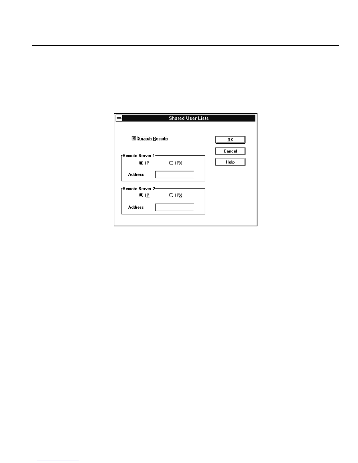
Chapter 6: User Records
To configure Shared User Lists:
1. Select or open the proper configuration file as described on page 32.
2. From the Users section of the Configuration File window, click the Shared Lists button. The
Shared User Lists dialog box appears.
3. Set the check box of the Search Remote field to enable the Perle 833 to search on remote servers.
4. Specify the location of Remote Server 1 and optionally Remote Server 2 by:
a) Select the Protocol supported by the remote server. The options are IP and IPX.
b) If IP is selected, enter the IP Address of the remote server. The address should be in dotted
decimal notation.
c) If IPX is selected, enter the Name of the remote server. The name can be up to 15 alpha-
numeric characters.
5. Click OK.
Call Back Options
Call back is a feature of the Perle 833 which can provide an additional level of security and at the
same time allows for centralized billing for telephone charges. When a remote user calls in to a Perle
833 and Call Back has been set up, the Perle 833 will disconnect and then call the user back
according to the Perle 833’s configuration for the user.
Perle 833 Remote Access Server Guide 75
Page 86
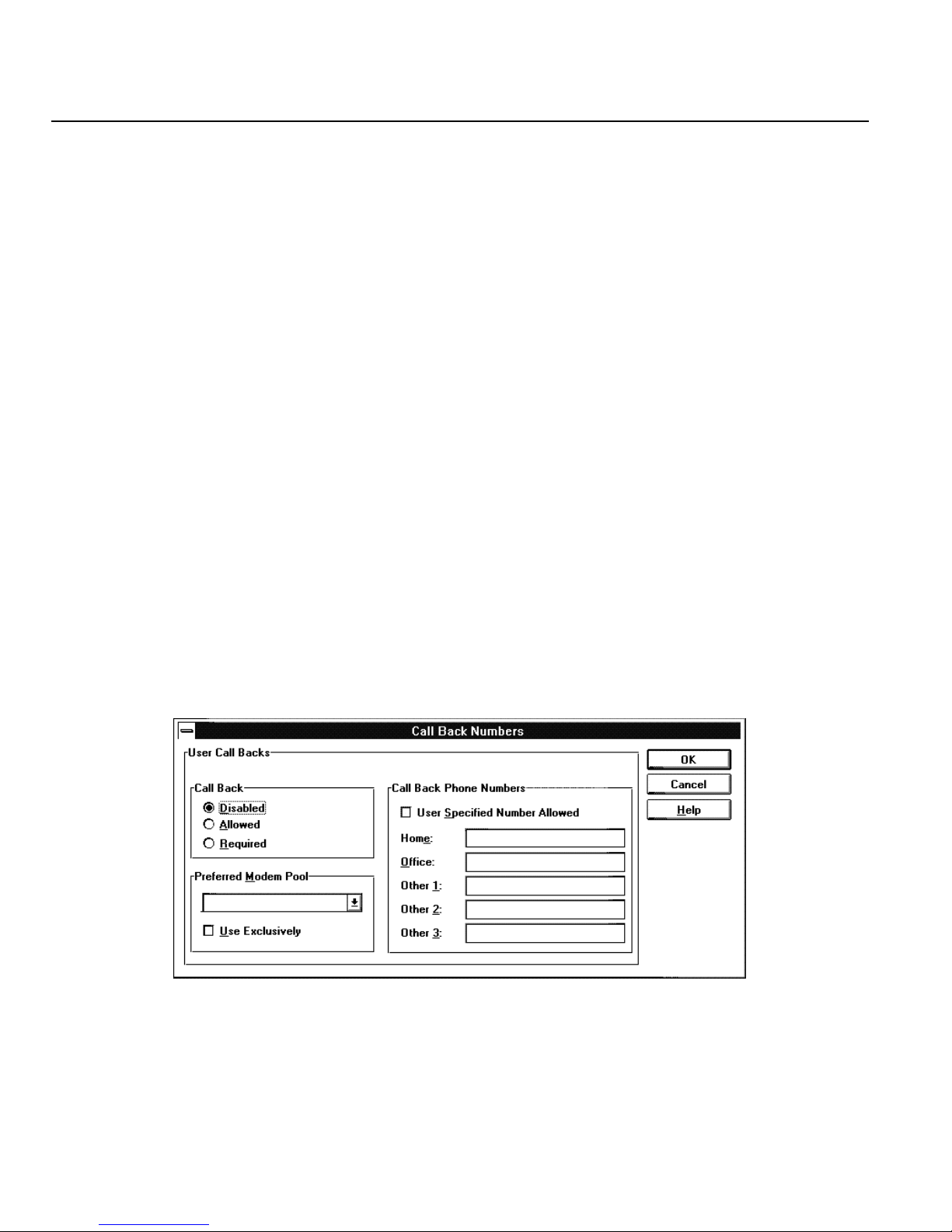
Call Back Options
Call Back Security
Call Back Security is controlled from the Perle 833 server. The settings can be either Disabled,
Required, or Allowed. When Required is selected, the user must be called back by the server. If Call
Back is not Requested on the dial-in client, then the Perle 833 server will disconnect the user and
will not call back.
The Perle 833 can be requested to dial back on one of five phone numbers it stores. (Since the actual
phone number is never transmitted on the serial line, an unauthorized user cannot attach to the Perle
833.)
Centralized Billing
Call Back can be used to centralize all phone charges for the Perle 833 server. The network
administrator configures the Perle 833 for Required Call Back. All dial-in clients will have to request
Call Back and as a result all telephone charges for the server will be billed to the telephone lines
connected to the server
To set up the Call Back Options:
1. From the Users section of the Configuration File window, click on Add to add new users, or
select an existing user and click Edit.
2. If necessary, configure a User ID, Department and Password for this user, and then press the
Call Back Options button.
The Call Back Options dialog box appears.
76 Perle 833 Remote Access Server Guide
Page 87

Chapter 6: User Records
3. Click the radio button for the Call Back option. The choices are:
• Disabled - Call back will not be used.
• Allowed - Call Back will be used if the dial-in user requests the feature.
• Required - Call back must be used. If the dial-in user does not request call back, the Perle
833 will disconnect the user and not call back.
4. Enable the User Specified Number Allowed feature if required by clicking the check box. If
call back is enabled, this feature allows a user to specify a call back number whenever the Perle
833 is called.
5. Up to five predefined telephone numbers can be entered for the call back option.
6. If you want to assign this user to a specific modem pool for Call Back, then make a selection in
the Preferred Modem Pool drop down list.
Note: Dial-In Modem Pool must be configured before a selection can be made. See “Dial-In
Modem Pools” below for configuration instructions.
If you click the Use Exclusively check box, the user will not be called back if a modem in the
pool is not available.
If you do not check the Use Exclusively box, the user will be called back using another pool if
no modems are available in the selected pool.
7. Click OK to save the Call Back Options.
User Filter Assignment
Use this window to assign up to 10 IP and 10 IPX filters to the user record. The server will process
these filters from the top down, so the order may be important.
To assign IP and/or IPX filters for the user, follow these steps:
1. Select a filter name from the Defined Filters pull-down list and click Add to add the filter to the
Assigned Filters list.
• You can change the order of the assigned filters by selecting a filter name from the
Assigned Filters list and clicking the Move Up or Move Down buttons.
• You can delete a filter assignment by selecting a filter name from the Assigned Filters list
and clicking the Remove button.
Perle 833 Remote Access Server Guide 77
Page 88

Dial-In Modem Pools
2. Set the Default Action to be taken if a packet does not match any assigned filter. The choices
are to Accept or Reject.
3. If you want to server to override the server assigned filters and only user the user assigned filters,
then click the check box on the Disable Server Filters field.
4. If you need to define more filters, then click the Define button in either the IP or the IPX section.
The IP Filter Definition or IPX Filter Definition dialog box appears.
5. Click OK to save your changes.
Dial-In Modem Pools
A modem pool is a modem or group of modems on a particular Perle 833 which can be can be used
for Call-Back, Dial-Out or both. This section describes the configuration and use of the Modem pools
for Dial-In services (see “Dial-Out Modem Pools” on page 91 for more information).
The purpose of dial-in modem pools is to group together modems or ports that have been configured
with similar parameters (i.e. same baud rate, or modem speed). As well, selected dial-in users can
be assigned to the modem pools. This in effect limits the use of modem pool to the selected users.
Up to 4 modem pools may be defined.
By default, no modem pools are defined. Call Back and Dial-Out are disabled.
Configuration Steps
Follow the steps below to define a modem pool on a Perle 833.
1. Open the desired configuration file.
2. From the Server section of the Configuration File window, choose Edit.
78 Perle 833 Remote Access Server Guide
Page 89
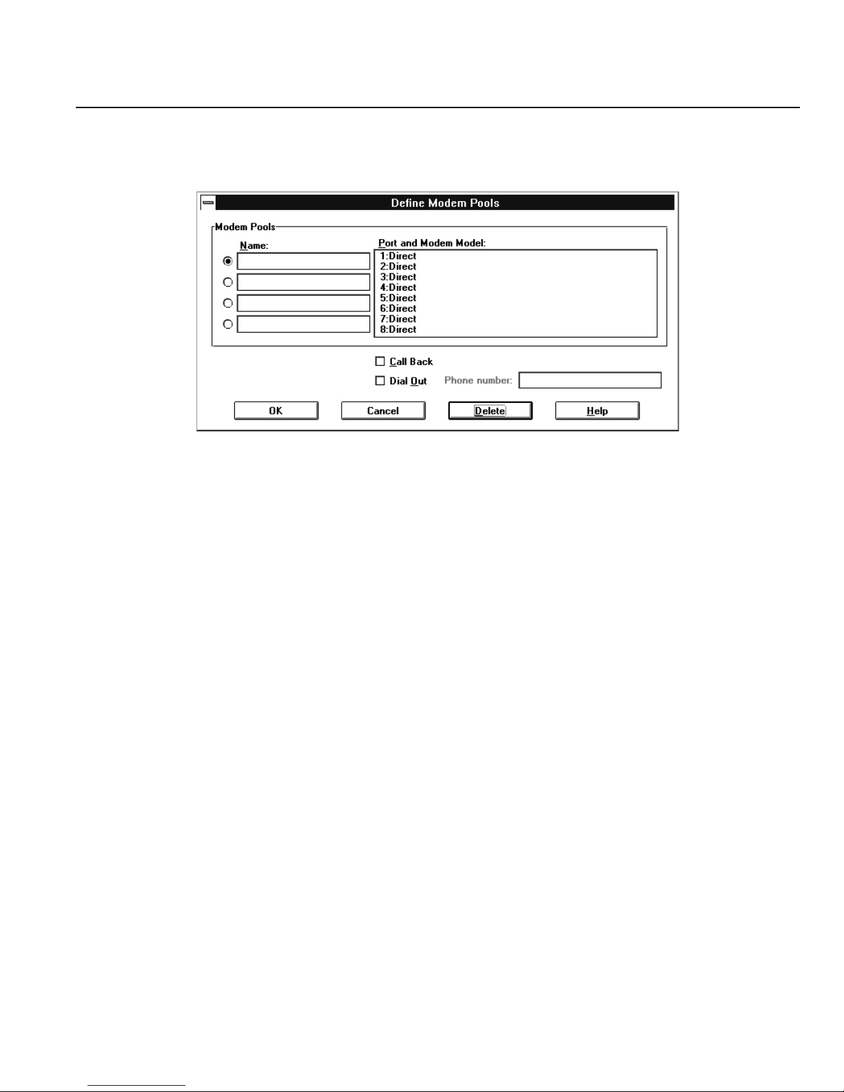
Chapter 6: User Records
3. From the Edit Server Options dialog box, click the Modem Pool button. The Define Modem
Pools dialog box appears.
4. Click the radio button to the left of the top Name field, and place the text cursor in that field.
Type a descriptive name for this modem pool.
5. Choose the modem or modems that will be in this pool from the list of Ports and Modem Models
at the right of the dialog box. To select more than one, press and hold the Shift key and click on
the desired modems.
6. Click the Dial In check box.
7. Click OK to return to the Edit Server Options dialog box. Click OK to save the modem pool.
Perle 833 Remote Access Server Guide 79
Page 90

Dial-In Modem Pools
80 Perle 833 Remote Access Server Guide
Page 91

Chapter 7: Dial-In
This chapter provides the details for configuring the Perle 833 for Dial-In. It also describes some
third party dial-in clients and any special considerations that are required for their use.
Overview
Dial-In allows remote users, using client software, to access a LAN and perform tasks as if they were
directly attached to it, using inexpensive voice-grade telephone circuits and asynchronous modems.
Configuring Dial-In
To configure the Perle 833 for dial-in:
1. Each port that will be used for dial-in will need to have the Dial-In function enabled. See “Serial
Port Options” on page 37.
2. A User record must be added to the User List for each dial-in user for security access. If the User
List will be used, see “Chapter 6: User Records” on page 71. This is the default security method.
If third party security options will be configured, see “Chapter 10: Security” on page 103.
3. A network protocol appropriate address (i.e. IP address, or MAC address) must be configured
for each dial-in user. This will depend on the network protocol being used on the LAN and the
dial-in client being used to access the LAN. See “Chapter 5: Configuring Network Protocols”
on page 47 for details.
4. Provide users with the necessary information for them to access the Perle 833. This will include:
•User Name
• Password
• MAC address for Perle Remote users if they are using Fixed MAC addressing.
• Call Back options.
5. Download the Configuration File to the Perle 833. See “Download the Configuration” on page
41.
6. Users need to install and configure their dial-in client. Refer to the client installation manual for
instructions. For the Perle Remote, see the Perle Remote User’s Guide.
Perle 833 Remote Access Server Guide 81
Page 92

Using Windows 95 Dial-up Networking
Using Windows 95 Dial-up Networking
Windows 95 contains all of the features necessary to connect with the Perle 833 server. With the
instructions in this chapter, connecting to your LAN through the Perle 833 using a dial-up
connection is a simple matter.
What You Need
The first step in connecting to a Perle 833 is to contact your network administrator to work out the
details of your User ID and password, as well as the phone number and other settings you may need
to know about. You may want to ask about IP addressing or Netware addressing features available
to you. You also need to perform the following tasks before configuring a connection.
1. Install a modem. 14.4 Kbps or higher is recommended.
2. Obtain a Windows 95 set of install disks or CD ROM for files that may be required.
Configuring a New Connection
The following steps will create a new connection for dial-up networking.
1. Locate the Dial-Up Networking icon and open it. It may be under My Computer on the desktop,
or under Accessories in the Program group.
2. Enter the name of your New Connection. For example, you may enter Perle 833. Also, select
the modem type and line speed you will be using. Click on Next.
3. Enter the telephone number of the modem to which you wish to connect. Click on Next.
4. After this process, Windows 95 creates an icon with the name of your Network Connection in
the Dial-Up Networking folder.
Note: Depending upon how your computer is configured, you may need to install networking
software manually using the Network icon in the control panel. If you will be supplying
an IP address from your PC, the network portion of your address must match the
network portion of the Perle 833’s IP address.
82 Perle 833 Remote Access Server Guide
Page 93

Chapter 7: Dial-In
Making a Dial-Up Networking Connection
1. Open the icon with the name of the Network Connection you want to make.
2. Fill in the required User ID and password information, and click on Connect. If everything has
been installed properly, the connection to the Perle 833 will pass you to your LAN.
3. When your LAN sign-on screen appears, perform a normal log in.
Call Back Options
The Perle 833 supports Call Back with the Window 95 dial-in client. To use this feature, the Perle
833 must be configured with the desired Call Back options. See “Call Back Options” on page 75 for
configuration instructions. Following is a list of these options and how Windows 95 operates with
them.
Disabled
• Call back not used
Required
• Call back must be used.
• If CANCEL is selected in the Windows 95 Client Callback dialog box, then the connection
will not be established.
Allowed
• The client has the option of using call back.
• If CANCEL is selected in the Windows 95 Client Callback dialog box, then the connection
will be established without call back.
Call Back Phone Numbers
• If any phone numbers have been configured in the Perle 833’s Call Back Phone Numbers
list then the first configured number will be used (order is home, office, other1, other2,
other3). The User Specified Number Allowed check box has no effect.
• If the phone number list is empty and the User Specified Number Allowed check box is
enabled, then the Windows 95 Client user will be allowed to enter a phone number for call
back.
Perle 833 Remote Access Server Guide 83
Page 94

Using Apple Remote Access
Using Apple Remote Access
The Perle 833 has built-in support for Apple Remote Access (ARA). Using Apple remote Access
Client software, your Macintosh can communicate with another Macintosh or an AppleTalk
Network. The Perle 833 supports both ARA Version 1 and 2.
In some instances, the modem scripts that are supplied with the Apple Remote Access (ARA) client
software may not work with the Perle 833. It is recommended that you use Version 2 ARA client
software.
If you are using a Version 1 ARA client, you must change the modem initialization settings for the
Perle 833. Version 1 ARA software requires that the modem does not negotiate compression or error
correction. Other dial-in clients and protocols will still work in most cases, but performance for these
clients could be degraded. See “Creating a Custom Modem Configuration” on page 133.
If you are using a Version 2 ARA client, the modem settings as shipped by Apple may not work. As
with the Version 1 client, you may disable error correction in the server. However, you can retain
your server settings by changing the modem configurations used with the ARA software. See your
modem vendor for these files. Also, the Apple Remote Access Modem Toolkit Version 2.0 available
from Apple will permit you to create custom modem configurations.
Configuration
To configure the Apple Remote Access Client, see your Apple Remote Access Client User’s Guide
for details.
Because ARA is always available in the Perle 833, no special configuration is required to enable
ARA. However, the client name and password must match the name and password of a user record
configured in the Perle 833. The name and password are used to access the Perle 833 only, and do
not correspond to names and passwords used to access other Macintoshes. See “Chapter 6: User
Records” on page 71 for more details on configuring a user record.
The Perle 833 also supports Call Back. To enable this option, you must set Call Back to Required in
the Perle 833 Manager and provide your home phone number. See “Call Back Options” on page 75
for more information. The client does not support other phone numbers or the Call Back Allowed
option.
84 Perle 833 Remote Access Server Guide
Page 95

Chapter 8: Dial-Out
This chapter provides the details for configuring the Perle 833 for the Dial-Out.
Overview
The Dial-Out support by the Perle 833 allows users on a LAN workstation to connect to a destination
that is external to their LAN. This is done by dialing out via a Perle 833 server modem instead of a
modem attached directly to the users’s PC. For dial-out users, the benefit of sharing these modems
across a network is that they can make efficient use of the hardware and phone lines that are already
installed on the network.
The user can connect to a BBS, internet provider or any other service accessible by the telephone
network.
Configuring Dial-Out
A summary of the configuration steps for dial-out are provided in this section. Later sections in this
chapter will provide more details.
1. Each port that will be used for dial-out will need to have the Dial-Out function enabled. See
“Serial Port Options” on page 37.
2. Configure the Dial-Out parameters for each port.
3. Configure the dial-out parameters for the server.
4. Configure Modem Pools.
5. Provide users with the necessary information for them to access the Perle 833. This will include:
• Modem Pool and /or Line Names.
6. Download the Configuration File to the Perle 833. See “Download the Configuration” on page
41.
7. Users need to install and configure the Perle 833 Dial-Out software on their PC. Refer to the
Perle 833 Dial-Out User’s Guide.
Perle 833 Remote Access Server Guide 85
Page 96
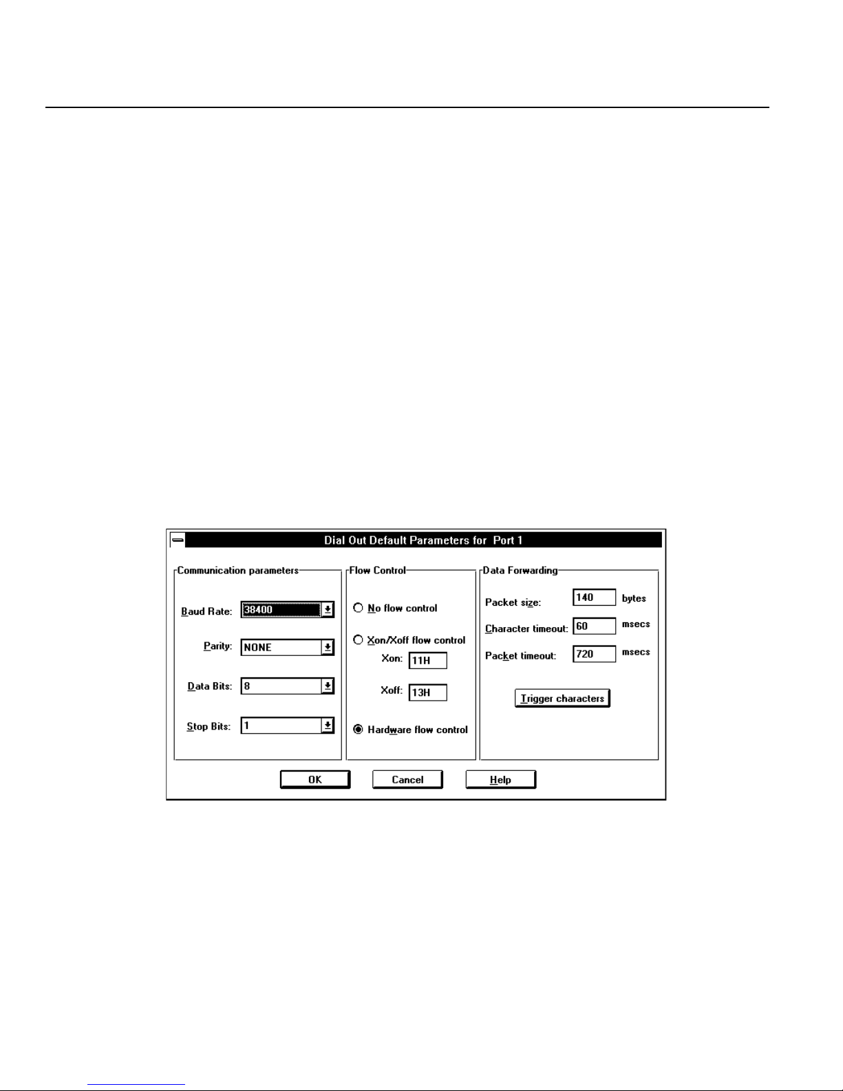
Port Dial-Out Parameters
Port Dial-Out Parameters
The Dial-Out parameters options are used to set up default communication options and flow control.
While the client has the option to override these settings, these are the default parameters the client
will use if the “use server defaults” option is enabled in the client software.
Note: It is important to note that the Flow Control and other parameters match the modem they
are being set up for. If the settings are different, a connection may not be possible.
Configuration Steps
Follow the procedure below to configure the Dial-Out parameters.
1. Open the configuration file for the appropriate Perle 833.
2. In the Port section of the Configuration File window, select the port or ports you want to
configure and click the Edit button.
3. Click the Dial-Out Parameters button. The Dial-Out Default Parameter for Port dialog box
appears:
4. Set the following parameters as required:
86 Perle 833 Remote Access Server Guide
Page 97

Communication Parameters
Baud Rate
The line speed used to transfer the data. Select the maximum speed supported by both the
modem and the communications program. The default rate is “38400” baud.
Parity
Select the parity type that matches the setting at the calling destination (contact the
destination site to verify this information) and in the dial-out client communications
program. The default setting is “NONE”.
Data Bits and Stop Bits
Select the data bits and stop bits that match the settings used at the calling destination and
in the dial-out client communications program. The default settings are “8” data bits and
“1” stop bit.
Flow Control
Select whether or not you want to use flow control and, if so, the type of flow control. Flow
Control regulates the flow of traffic between the server port and the modem. Match the
selection to a comparable setting in the communications program.
Chapter 8: Dial-Out
Select one of the following options:
• No flow control.
• Xon/Xoff flow control (to use the software flow control). The Xon/Xoff fields display
standard industry values. You should never need to change these values.
• Hardware flow control. This is the default setting and one that can be used throughout
the system, including the server, client, application and modem for almost all situations.
Data Forwarding
Packet Size
Enter the size of the individual network transmissions. “Packets” are blocks of data
transmitted on a network. Consider the following implications before you make any changes
to the default setting. Setting the number lower results in more frequent network
transmissions because packets are always sent when they are full. This change results in
higher network traffic. Due to these implications, do not change the packet size unless you
have a specific reason to do so. The default setting is “140” bytes. The minimum is 1 and
the maximum settings is 512. If you do change the packet size, review the setting for packet
timeout.
Perle 833 Remote Access Server Guide 87
Page 98
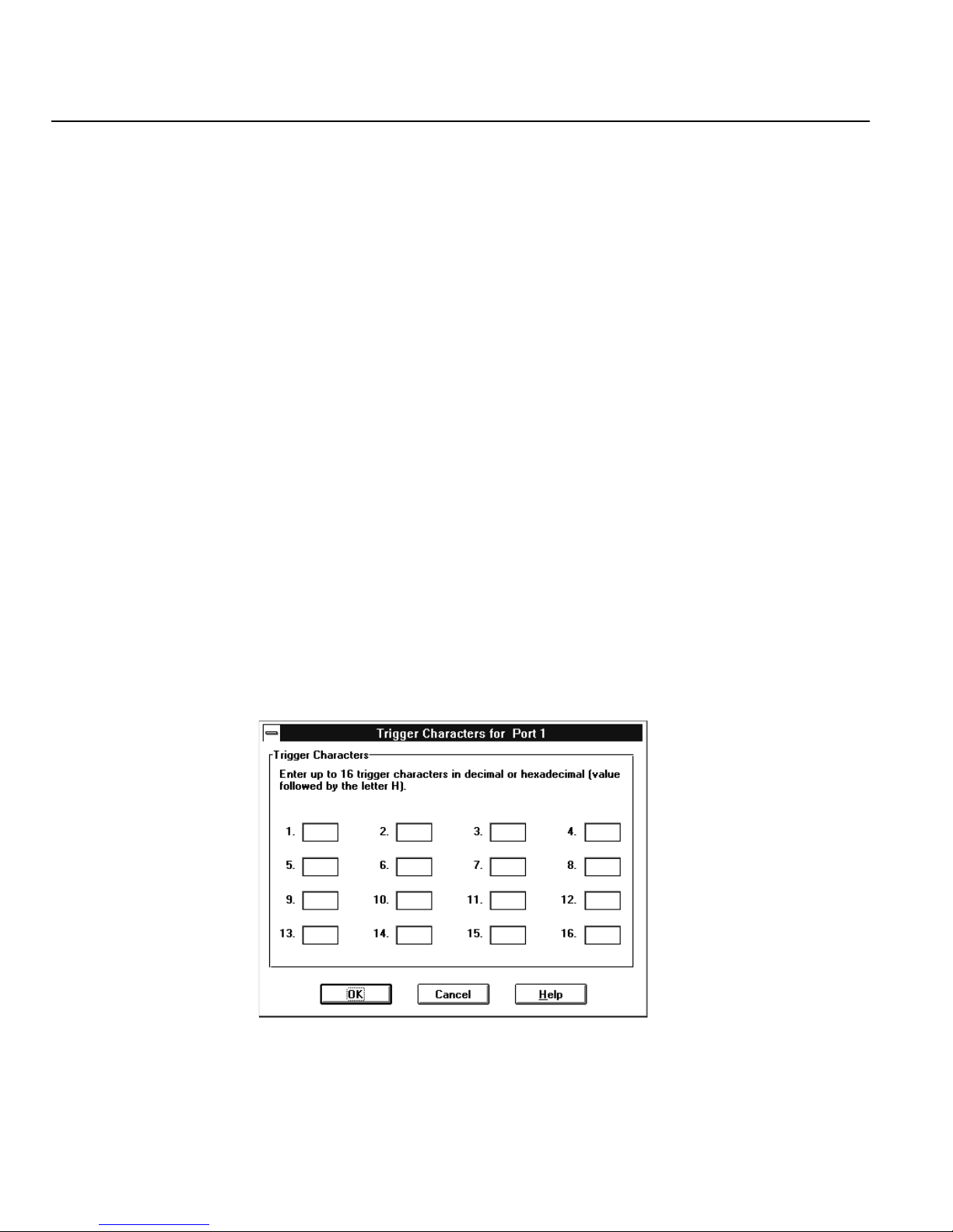
Port Dial-Out Parameters
Character Timeout
Enter the duration of the character timeout in milliseconds. “Character Timeout” is the
maximum amount of time that can elapse without a character being sent. The packet is
transmitted after the time period has elapsed. Consider the following implications before
you make any changes to the default setting. Setting the number lower can improve the
responsiveness of the system if you are typing data, but may result in higher network traffic.
To ensure this setting is valid, make sure the number is lower than the “Packet timeout”
number. Network packets are always sent when they are filled, or if the packet timeout
expires. The default installation setting is “60” milliseconds. The minimum is 0 and the
maximum is 65535. A value of “0” disables the timer.
Packet Timeout
Enter the duration of the packet timeout in milliseconds. “Packet Timeout” is the maximum
amount of time that a packet will wait for data before the packet is sent. Packet timeout
begins countdown when the first character is placed in a packet. Consider the following
implications before you make any changes to the default setting. If the typical data
transmission is smaller than a packet, lower the number. This can improve the
responsiveness of the system. The default installation setting is “720” milliseconds. The
minimum is 0 and the maximum is 65535. A value of “0” disables the timer.
5. Trigger Characters
Set trigger characters only if you have very specific communications needs. They are not for
general use. Click on the Trigger Characters button and the Trigger Character for Port dialog
box appears
88 Perle 833 Remote Access Server Guide
Page 99

Chapter 8: Dial-Out
A trigger is a character that forces the transmission of a network packet. Data characters
accumulate in packets when they are received from the phone line or sent from the modem.
These packets are sent under one of the following circumstances:
• a packet is filled
• a character timeout occurs
• a packet timeout occurs
• a trigger character is encountered.
Enter up to 16 characters in decimal or hexadecimal (followed by the letter H). The default
setting is none, that is, the 16 boxes are empty.
Case scenario:
If you are doing many file transfers and you know that each data transmission block ends with
a consistent, unique end character, then you can define this character as a trigger. This will ensure
that when a block of data has been received, it is forwarded immediately.
6. Click OK on the Trigger Characters for Port dialog box to accept the changes.
7. Click OK on the Dial-Out Default Parameter for Port to accept the dial-out parameter changes
or click Cancel to exit without saving.
Perle 833 Remote Access Server Guide 89
Page 100

Server Dial-Out Parameters
Server Dial-Out Parameters
The server dial-out parameters apply to all dial-out connections. Client Timeout is the only
configurable parameter.
Configuration Steps
Follow the procedure below to configure the Dial-Out parameters.
1. Open the configuration file for the appropriate Perle 833.
2. In the Server section of the Configuration File window, click the Edit button.
3. From the Edit Server Options dialog box, click the Dial-Out button.
4. The Dial-Out dialog box appears. Enter a value for the Client Timeout period in minutes. The
Perle 833 will periodically check to make sure the client is connected to the LAN. If the client
has been disconnected for the Client Timeout period, then the modem can be released. The
default is 1 minute.
5. Click OK.
90 Perle 833 Remote Access Server Guide
 Loading...