


ver. 1.0 PRINTED IN KOREA
01-CM-709M1
Thank you for purchasing this product.
For proper usages and application,
Please read this instruction manual thoroughly.
INSTRUCTION MANUAL
※ Design and speci cations could be changed without notices.

3
This unit has been tested and found
to comply with the limits for a Class B
digital device, pursuant to Part 15 of
the FCC Rules.
These limits are designed to provide
reasonable protection against
harmful interference in a residential
installation. This unit generates, uses,
and can radiate radio frequency
energy, and, if not installed and used
in accordance with the instructions,
may cause harmful interference to
radio communications.
However, there is no guarantee that
interference will not occur in a
particular Installation.
If this unit does cause harmful
interference to radio or television
reception, which can be determined
by turning the equipment o and on,
the user is encouraged to consult the
dealer or an experienced
radio/TV technician for help.
■ INFORMATION FOR USERS:
■ CHANGES OR MODIFICATIONS TO
■ THIS PRODUCT NOT APPROVED BY
■ THE MANUFACTURER WILL VOID
■ THE WARRANTY AND WILL VIOLATE
■ FCC APPROVAL.
CONTENTS
Safety Instructions .................................................................................. 4
1. Box Contents .......................................................................................... 6
2. Features .................................................................................................... 7
3. Before Use ............................................................................................... 8
4. Names of the Monitor Buttons ........................................................ 8
5. Remote Control ..................................................................................... 9
6. Functions .............................................................................................. 10
7. Connection ........................................................................................... 15
8. Installation ............................................................................................ 16
9. Speci cations ...................................................................................... 19

4 5
WARNING
Please read the “Safety Rules” carefully before using this product. Following the
safety rules prevents users from damages related with the misuse of the product.
It is very important to follow these safety rules. We state “Caution” and “Warning”
to clarify any potential risk for a damage associated with the misuse of the product.
Do not put the product in place where sudden temperature increasing and
should use on optimum voltage, temperature and humidity.
--- It may cause to electronic shock or malfunction.
Do not get product wet and operate with wet hands.
--- It may cause to electronic shock or malfunction.
Do not place where interfere with visual eld and watch or operate monitor
during driving.
--- It may cause tra c accident.
Do not place near of air bag e ective range.
--- It may cause malfunction of air bag or accident, injury due to hitting
--- monitor by air bag.
Keep clean dust on power socket.
--- It may cause electronic shock and re by bad connection.
Do not pull cord with a jerk, should catch a plug and pull.
Do not use damaged cord.
--- It may cause cord malfunction, electronic shock and re.
When clean exterior, power o and wipe with dry cloth.
--- Wet cloth may cause a electronic shock.
Do not clean exterior with volatility or oily solvent.
Neither keep touching rubber and plastic for long time.
--- It may cause change of surface, fall of paint, malfunction and re.
1 Safety Instructions
May cause bodily harm or even
death if the user ignores these
warnings in the safety rules.
Warning
May cause a damage or shorten
the life time of the product if the
user ignores these cautions in
the safety rules.
Caution
CAUTION
Do not place where vibration and shock.
--- It may cause throw down and then malfunction and accident.
Do not put metals as like pin and needle into hole and chink of grill, speaker.
--- In case of inserting them, stop to operate, it may cause electronic shock,
--- re and malfunction.
Do not use in problem condition as like smoking, smell something burn.
--- It may cause re. Stop to use and make inquiries to agency.
Do not disassemble, repair and remodeling.
--- It may cause malfunction and injury, can not get warranty.
--- Make inquiries to agent for repair and checkup.
Should install while power o . (After install products, connect DC jack)
--- It may cause to electronic shock or malfunction.
Do not push a LCD panel.
--- It may cause LCD broken.
In case of inserting battery, attend to polarity and insert according to
direction
--- When wrong inserting, it may cause re, damage by explosion.
While stop driving (parking), set the car in motion.
--- It may cause battery discharge.
Do not use multi socket or extended adaptor.
--- It may cause unexpected heating, re and malfunction.
Unplug product when do not use for a long time.
--- It may case re by short circuit due to heating.
Do not place near magnet.
--- It may cause malfunction and trouble.

6 7
Bracket & Screw setMonitor
Monitor cable
Stand
(Option)
■ Application of 7.0” WIDE TFT LCD with high resolution and low re ection
■ All functions are displayed on screen (OSD function)
■ 7 Language Display Selection
■ (ENGLISH-DEUTSCH-ITALIANO-FRANÇAIS-ESPAñON-한국어-日本語)
■ Picture quality control (PWM control)
■ Free voltage (From DC12V to DC24V)
■ Dimmer selection function
■ Camera input (3 system)/Work together with back gear/side signal
■ Video input (video/mono audio)
■ Wireless remote controller (option)
■ This product adopts tilting function so watching
■ is possible from wanted angle.
Cigar cable
Instruction
Manual
Remote Controller
(Option)
Sun Visor (Option)
1 Box Contents 2 Features
Bracket Cover
(Option) U Bracket (Option)

8 9
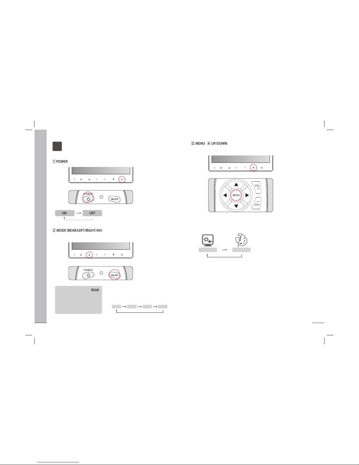
① POWER
② MODE
③ ▲▼
④ ◀▶(VOL+/-)
⑤ MENU
⑥ AUTO PIC
⑦ MUTE
⑧ RECALL
Turning the power on/o
Selecting REAR/LEFT/RIGHT/AV
Moving up/down on menu
Changing volume or MENU level
Selecting MENU and changing functions
Adjusting the screen setting
Mute mode on/o
Displaying the current mode and volume level
3 Before Use 5 Remote Control (option)
AV MODE DOWN/UP MENU
SENSOR
(REMOTE)
POWER
4 Names of the Monitor Buttons
※Not back up vehicle while relying only on the monitor Image and use slow ※
speeds when backing up.
※The rear-view monitor image has the same right-left inversion as your
※vehicle’s rearview mirrors. Depending on the vehicle, the eld and angle of
※view may di er.
▣ Precautions (when you use the monitor)
■ Screen may be a little dark when the product is operated in low tempera-■
■ ture areas. Screen will show normal luminosity after a few minutes.
■ When you install the product in a car and watch monitor, the car engine
■ should be running as there might occur excessive discharge of the car
■ battery.
■ Cover the product when exposed to direct rays of the sun for a long period
■ of time.
■ (You should keep the product at a temperature range of -4℉ ~ 158℉)
10 11
(1) Press [MENU] button to select MAIN MENU, changed color in red when it is
(1) selected.
(1) * Every time the button is pressed, the setting changes.
(2) Press [▲▼] button to select SUB MENU, changed color in red when it is selected.
(2) * Every time the button is pressed, the setting changes.
(3) Press [◀▶] button to change settings.
(1) Press [MODE] button.
(1) The characters of REAR, LEFT, RIGHT,
(1) AV appear on the screen and they
(1) disappear after 5 seconds.
(1) Press [POWER] button to the power.
(1) (STAND BY state is OFF)
(2) Press [POWER] button again to o
(2) the power. (STAND BY state is ON)
AV MODE DOWN/UP MENU POWER
AV MODE DOWN/UP MENU POWER
MONITOR
REMOTE
CONTROL
MONITOR
REMOTE
CONTROL
■ It is a function to change MODE (REAR/LEFT/RIGHT/AV)
REAR LEFT RIGHT AV
MONITOR
REMOTE
CONTROL
AV MODE DOWN/UP MENU POWER
■ It is a function to select MAIN MENU (SETUP/PICTURE)
SETUP PICTURE
* Note : In the mirror mode, the character is inverted.
* If there is no video signal in the mode, it will be skipped in the toggling mode.
6 Functions

12 13
(1) Press [▶,VOL+] button to turn up
(1) the volume.
(2) Press [◀,VOL-] button to turn dwon
(2) the volume.
REAR
MONITOR
AV MODE DOWN/UP MENU POWER
■ It is a function to change AV MODE.
CONTRAST
BRIGHTNESS
COLOR
TINT
70
40
40
40
CONTRAST
BRIGHTNESS
COLOR
TINT
70
40
40
40
CONTRAST
BRIGHTNESS
COLOR
TINT
70
40
40
40
CONTRAST
BRIGHTNESS
COLOR
TINT
70
40
40
40
■ CONTRAST
■ COLOR
■ BRIGHTNESS
■ TINT
LEFT
RIGHT AV
AV
■ RESET
■ A factory default reset will clear all of OSD information.
MONITOR
REMOTE
CONTROL
AV MODE DOWN/UP MENU POWER
■ DIMMER
■ LANGUAGE
■ DIRECTION (Inverted upside down)
■ DISPLAY (Screen size)
DIMMER
LANGUAGE
DIRECTION
DISPLAY
RESET
FRANCAIS ESPAnONENGLISH DEUTSCH ITALIANO
한국어
日本語
ENGLISH
0˚
WIDE
▶
DIMMER
LANGUAGE
DIRECTION
DISPLAY
RESET
ENGLISH
180˚
WIDE
▶
FULLWIDE NORMAL CINEMA

14 15
REMOTE
CONTROL
REMOTE
CONTROL
REMOTE
CONTROL
FULLWIDE NORMAL CINEMA
(1) Press [MUTE] button to mute the
(1) sound.
(2) Press [MUTE] button again to
(2) cancel.
(1) Displaying the current mode and volume level.
(1) Press [AUTO PIC] button to select the screen size.
7 Connection
(option)
(option)
(option)

16 17
8 Installation
Appoint attaching place and put together the monitor and bracket as follows
installation drawing. Insert combined monitor after arranging connecting cable
inside.
Exposure Type >> (Bracket Cover : OPTION)
Inserting Type >>
1
2
Monitor installation with stand & sun visor >> (OPTION)
3
※ When you use the monitor exposurely , bracket cover make clean side of
monitor.
PORON TAPE
VELCRO TAPE
NOTICE
TAPPING SCREW T1 M4 X 10 (4ea)
MACHINE SCREW M3 X 5 (6ea)
TAPPING SCREW T1 M4.0 X 12 (3ea)
INSERT BOLT (2ea)
FLAT WASHER M3 (4ea)
(1) Remove a protecting tape and attach stand place.
(2) Fix a stand with taping screw.
(3)&(4) Connect stand and monitor and x a height of monitor with x knob.
(5) Then attach a sunvisor to monitor side and x it with a screw.
⑤
⑥
⑥
FOAM TAPE

18 19
LCD Panel
Screen size
Number of pixel
Brightness
Voltage
Current
Horizental
Vertical
Video signal
Audeo signal
Input system
Speaker
Language display selection
User controls
Operating temperature
Storage temperature
Dimension(W x H x D)
Power supply
Frequency
Input signal
7 inch
480(W) x 3(RGB) x 234(H)
450 NIT
View angle(L/R/U/D)
60/60/40/60
DC 12V-24V
450mA (DC 12V, monitor set only)
AUTO (NTSC/PAL)
15.734 KHz 15.625KHz
60 H z 50 H z
Composite video signal
MONO signal 400mVrms
0.5Watt max
7 Language
Power, Mode, Menu, Up, Down, AV
14℉~140℉ (-10℃~60℃)
-4℉~158℉ (-20℃~70℃)
7.9(W) x 4.76(H) x 1.21(D) inch
201(W) x 121(H) x 30.7(D) mm
Weight
1 lb (500g)
NT SC PAL
Monitor cable ass’y
Cigar cable
Bracket & screws set
Bracket cover
U-Bracket (option)
Accessories
9 Speci cations
Contrast ratio
300 : 1
Installation with u-bracket & sun visor >> (OPTION)
4
(1) Place U-bracket and x it with enclosed screw.
(2) Put xed bracket to monitor and screw down with bolt both side.
TAPPING SCREW T1 M4.0 X 10 (3ea)
INSERT BOLT (2ea)
SPRING WASHER M4 (5ea)
FLAT WASHER M4 (5ea)
Remote controller (Included with battery)(option)
Sun visor (option)
Stand (option)
PORON TAPE
⑤
⑤
PORON TAPE
⑤
⑤
 Loading...