

Page 1

TABLE OF CONTENTS
INTRODUCTION 4
GENERAL SPECIFICATIONS 4
SITE PREPARATION 6
INSTALLATION 7
OFFSETS 10
INSTALLATION – MECHANICAL 11
INSTALLATION – ELECTRICAL 12
TRANSMITTER WIRING 12
OP ERATING INS TRUC TIO NS 15
ELECTRICAL ALIGNMENT 19
SENSITIVITY ADJUSTMENT 20
THEORY OF OPERATION 21
TROUBLESHOOTING 24
TEST POINTS 24
i
Page 2

IGURE
F
IGURE
F
IGURE
F
IGURE
F
IGURE
F
IGURE
F
IGURE
F
M
1:
S
YSTEM COMPONENTS
2:
R
3:
T
ERRAIN
4:
P
HYSICAL PROTECTION
5:
P
6:
O
7:
24000
ODEL
EQUIRED CLEARANCE AREA
....................................................................................................4
.............................................................................................................8
ERIMETER LAYOUT
FFSET ILLUSTRATION
.......................................................................................6
............................................................................8
......................................................................................9
........................................................................................10
.....................................................................................10
IGURE
F
IGURE
F
IGURE
F
IGURE
F
IGURE
F
IGURE
F
IGURE
F
IGURE
F
IGURE
F
IGURE
F
O
FFSET ARRANGEMENTS
8:
P
OST INSTALLATION AND MOUNTING UNITS
9:
M
OUNTING HEIGHT CHART
10:
T
RANSMITTER WIRING
11:
R
ECEIVER WIRING
12:
A
NTENNA CONFIGURATIONS
13:
T
RANSMITTER BLOCK DIAGRAM
14:
R
ECEIVER BLOCK DIAGRAM
15:
T
RANSMITTER CIRCUIT BOARD COMPONENT LOCATION
16:
R
ECEIVER CIRCUIT BOARD COMPONENT LOCATION
17:
: T
YPICAL HIGH SECURITY INSTALLATION
.
.........................
...................................................................................14
..........................................................................................17
..........................................................................19
....................................................................22
..........................................................................23
E
RROR
E
RROR
................11
! B
OOKMARK NOT DEFINED
! B
OOKMARK NOT DEFINED
...............................26
......................................27
.
.
ii
Page 3
iii
Page 4

Introduction
The Perimeter Products, inc. Model 24000 Bi-Static Microwave Link consists of a
microwave transmitter and a receiver unit. Each system is designed to detect motion in a
specified area called a detection zone. This detection zone is established by the
transmitter, which sends continuous microwave signals to the receiver. Any motion in
the detection zone causes a variation in the received signal strength. These signal
variations are detected by the receiver and processed to give an intrusion notification.
Each transmitter and receiver is mounted in a weatherproof enclosure. Each enclosure
contains the respective electronic circuitry, and may be wired to report attempts of
tampering. An antenna is part of each electronic enclosure. The antenna on the
transmitter contains the microwave source. The receiver antenna contains the microwave
detector.
This Installation and Operations Manual is intended for the pe rson who will be doing the
initial site layout and installation of the PPi Microwave Intrusion Detection System.,
Model 24000. It provides the information required to install your system from the time
of unpacking shipped equipment to verification of an opera tive system after installation.
This manual covers site preparation, installation procedures, operating instructions and
general theory of operation
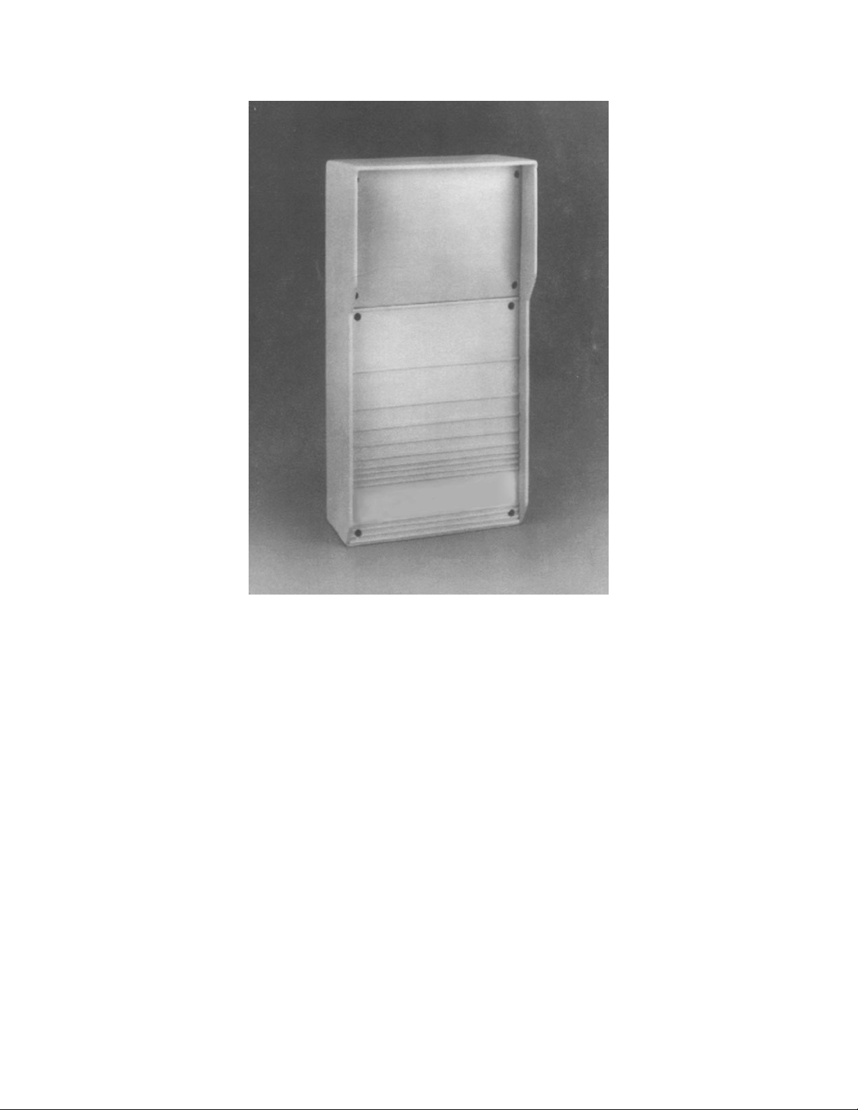
Figure 1: Model 24000
GENERAL SPECIFICATIONS
Circuit Components 100% solid state
4
Page 5

Power R e quirements 11 to 15 VDC
Can be provided by PPi Unin te rru ptible Power
Supply UPS-PFI
Power Consumption 100 MA total per system maximum
Tra ns mitter 70 MA
Receiver 30 MA
Microw ave Carrier Frq. 24.125 GHz +/- 5 0 MHz
Operating Range 800 ft., 243 meters
Antenna Pattern Sh ort Range 24°
Medium Range 16°
Long Range 11°
Antenna P olarization E-Plane Vert ic al
(E-Plane Horizontal Optional)
Operating Tempera ture -40°F to +158° F
(-40°C to + 70°C)
Dimensions 6” W X 3.5” D X 12.5 “ H
16 cm W X 9 cm D X 32cm H
Weight 5 lbs ., 2. 25kg
Shipping Weight 8 lbs., 3.5kg
Transmitter Unit
Tamper Circuit Contact 1A, 28 VDC
Modulation Type: square wave type A2
Channels: 6 field selectable
Microw ave Outpu t Less than . 25 volts/meter, maximum at 98 Ft.
(30 m e te rs)
Remo te T e sting Built-in self-test generator simu la tes acutual
intrusion signals
Receiver Unit
Demodulation Correlated balanced demodulator
Alar m Relay 2A at 28 VD C
5
Page 6
Alarm Duratio n Adju s table .5 sec. To 10 sec.
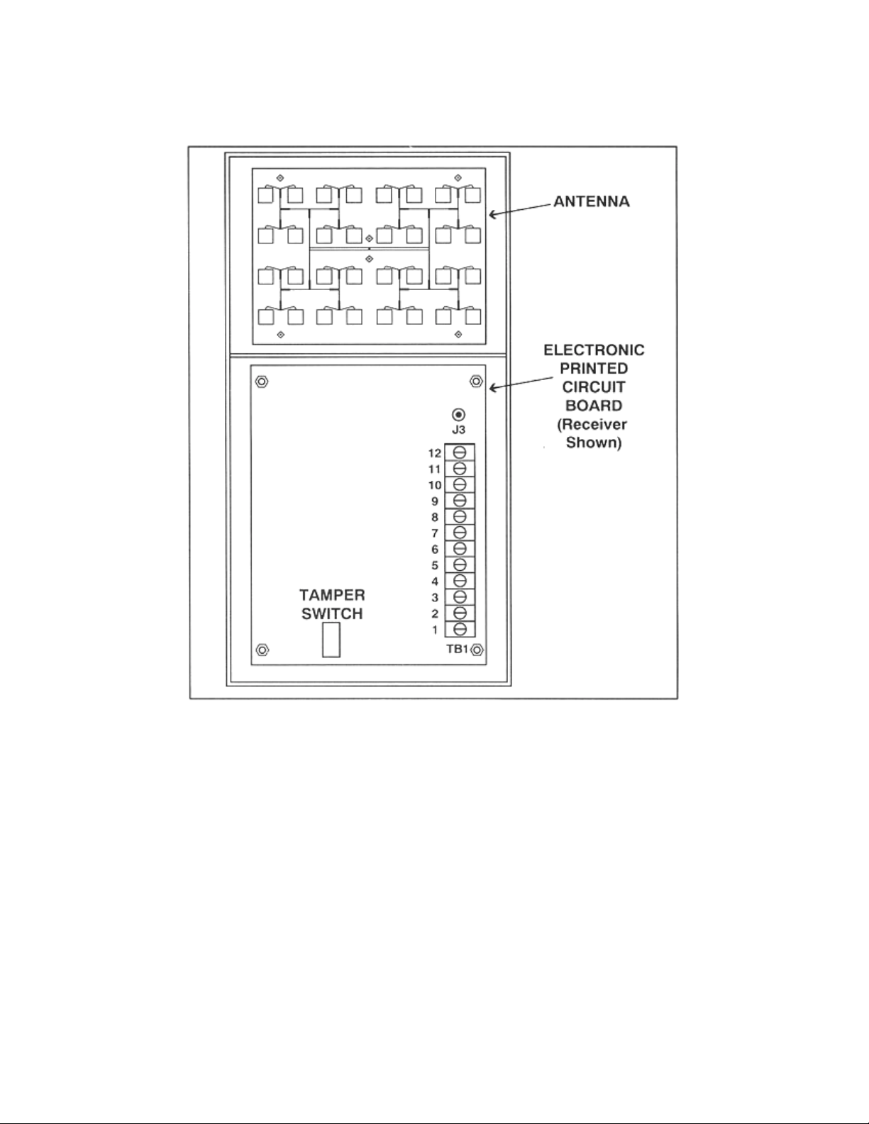
Figure 2: System Components
SITE PREPARATION
Site preparation is necessary for satisfactory performance of the Model 24000 unit. The
amount and type of site preparation required depends on the level of security desired.
The physical specifications for a high security detection zone are:
• Transmitter/receiver separation distance no longer than 328 ft. (100 meters)
• Terrain must be level to grade, +/- 3 in. (7.6cm)
6
Page 7

• Terrain void of vegetation
• Transmitter/receiver units mounted 24 in. (60cm) beam centerline (center of
antenna) to ground
When physical properties of the detection zone are not within these parameters, the
system capabilities are diminished. High security applications require much more
stringent specifications than do applications where only a beam-break alarm is required.
The following parameters should be used to determine the level of security required.
High Security Zone – Detection of intruder stomach-crawling parallel to the beam
Medium Security Zone – Detection of intruder crawling on hands and knees.
Low Security Zone – Beam-break alarm only – detection of a walking intruder,
vehicles, etc. (not recommended)
INSTALLATION
Installation should begin with a survey of the area to be covered to ensure that it meets
the site requirements. After the location of Transmitters and Receivers has been
determined, poles should be set and conduit terminated. The Model 24000 can then be
mounted, wir in g completed and the system configured by setting t he a ppropriate jumpers
and switches.
Location of Model 24000
1. Required area.
zone will be determined by the amount of open space to the left and the right of
cente rline between the Transmitter and Receiver. Generally, there should be a clear open
space that exceeds one half the pattern width on each side.
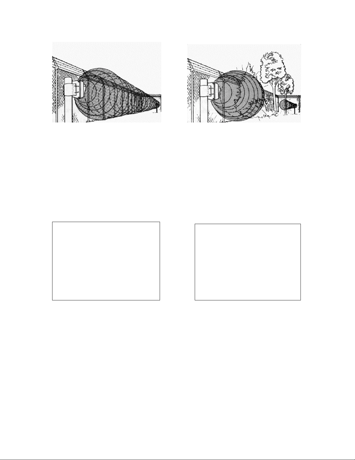
The area to be protected should be free of obstructions and moving objects such as tre es,
shrubs, bushes, obstacles such as utility boxes and other structures. Refer to Figure 3.
The length of each zone must be established first. The width of the
7
Page 8
DO DON'T
Figure 3: Required Clearance Area
2. Terrain
to Receiver, it is important to maintain a clear line of sight between the units; therefore,
the ground must be flat across the protected area. Any bumps, hills or ditches must be
filled so that the area is flat to within (6) inches (15cm). Refer to Figure 4.
The protected area can be any stable, reasonably smooth material such as concrete,
asphalt, tilled earth, or gravel. If there is grass or vegetation in the protected area, it must
be kept cut to a maximum of three (3) inches (8cm) in height. A Model 24000 should not
be operated over open water, or where standing puddles will form.
Since operation of the link requires transmission of energy from Transmitter
DO DON'T
Figure 4: Terrain
3. Microwave Signal Considerations
construction materials such as glass, plaster and drywall. Microwave signals will reflect
off of solid objects and metallic surfaces.
Microwave signals will pass through standard chain link fences if the beam axis is at a
right angle to the fence. The more the fence deviates from a right angle to the beam, the
less signal penetration, and the more reflection.
. Microwave signals can pass through common
8
Page 9
Microwave signals that detect a moving or ”flexing” fence, or other large metallic
objects, can generate nuisance alarms. The large size of a metallic object can cause a
small amount of motion to appear as a large moving object.
Other potential nuisance alarm sources include: moving machinery parts, as well as the
vibrations caused by machinery, large vehicles such as trucks, buses and aircraft.
4. Physical Protection
protection from accidental damage as well as from tampering. If units must be installed
near roadways or where they will be vulnerable to vehicle traffic, installin g devices such
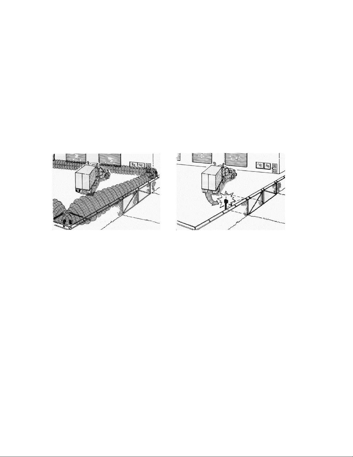
as bumper posts or parking guards can provide additional protection. See Figure 5.
. Install the Transmitter and Receiver in a location which provides
DO DON'T
Figure 5: Physical Protection
5. Optimum Security
from nuisance alarms. Always locate Model 24000 inside a fence or controlled access
area to prevent unwanted alarms due to random foot traffic, vehicles, or animals.
Units should be located several feet away from paralle l fences to avoid reflection of the
microwave signal off the surface of the fence, and to prevent the possibility of jumpin g
over the protection pattern.
For maximu m security it is necessary to overlap the ends of links so that the dead spot
below and immediately in front of the adjoining link is protected. A 15 foot overlap is
required at corners and a 30 foot overlap at intermediate points. The offset of overlapping
in-line links should be approximately 18 inches (46cm), measured from the center of each
unit.
Note that at each point of overlap either two Transmitters or two Receivers should be
installed. This arrangement prevents an adjacent Transmitter and Receiver from
. Choose a location that will provide optimum security, yet be free
9
Page 10
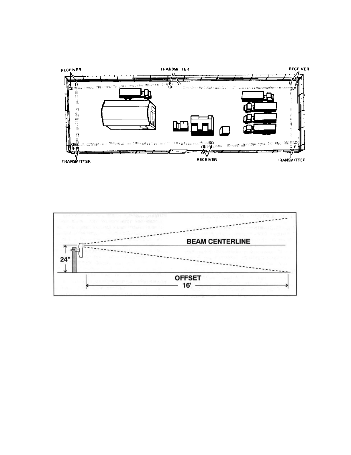
establishing an unwanted link across the short overlap distance which could result in a
Jam or Wrong Channel indication at the Receiver. Refer to Figure 6.
Fi gure 6: Perimeter Layout
Figure 7: Offset Illustration
OFFSETS
The area immediately below the transmitter/receiver antenna is not exposed to the sensor
system’s microwave energy. To compensate for this unmonitored area, an offset of the
sensor system is required. (see Figure 7). Offsets prevent the possibility of intruders
crawling unde r or jumping over a transmitter or receiver to gain access to the protected
area. The offset distances are based on the transmitter/receiver mounted at a height of 24
inches (beam centerline to ground). As the mounting height of the transmitter or receiver
is increased, a longer offset is necessary. Different types of offsets are shown in Figure 8
10
Page 11
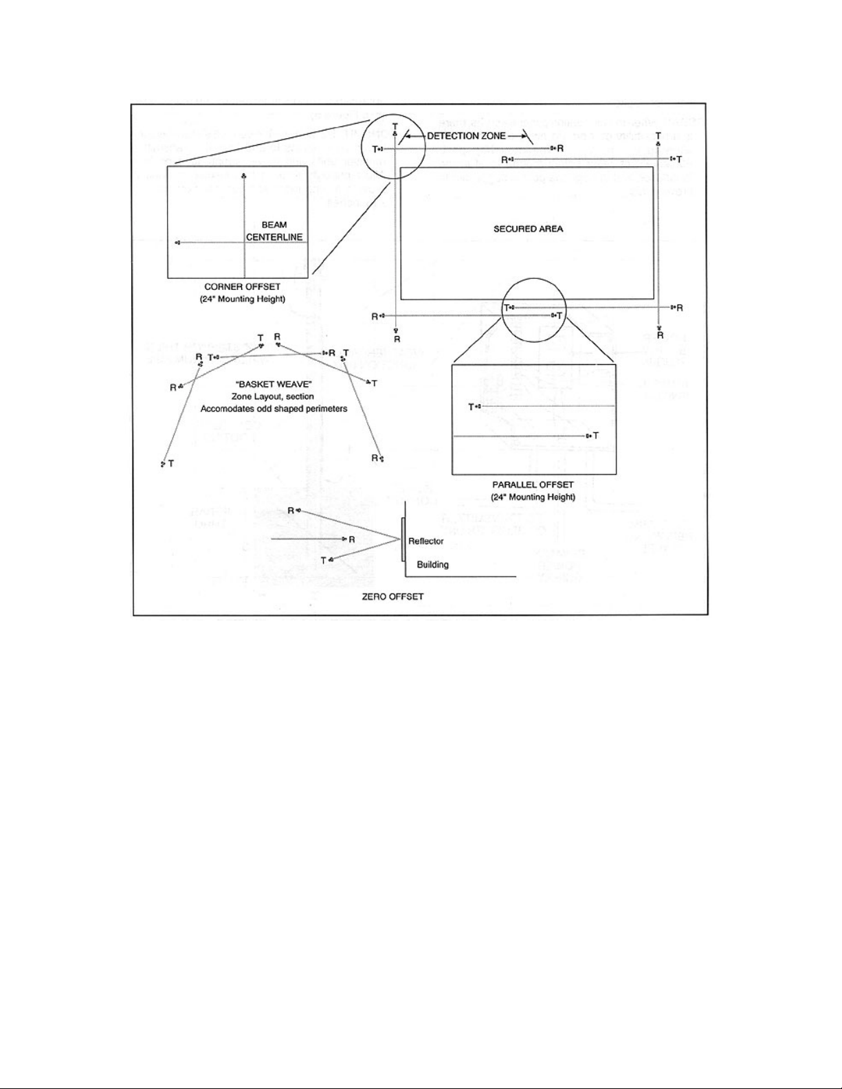
Figure 8: Offset Arrangements: Typical High Security Installation
INSTALLATION – MECHANICAL
Mounting Units
Both the transmitter and receiver must be securely mounted to prevent movement or
vibration. Excessive movement or vibration of either unit will cause nuisance alarms.
Windy conditions a re a potential problem if the units are not mounted properly. Refer t o
Figure 9 for a visual overview of the following instructions.
Foundation
The foundation for the mounting posts in normal soil should be at least 3 fee t dee p and 2
feet in diameter. If soil conditions are such that a non-shifting foundation is questionable,
then a larger footing should be considered. In areas where extremely low t emperatures
may cause frost heaving, use a truncated pyramid base foundation.
11
Page 12

Node Curves
The node curves (N1, N2, N3, and N4) represent the pivot point for coordinating distance
(horizontal axis) to mounting height (vertical axis). Those mounting height and distance
coordinate lines that meet in the area between the node curves should be avoided.
Coordinate lines that meet on the node curves are preferred because they will result in
higher signal strength at the receiver and a wider fade margin. However, choosing a
mounting height at N1 or below will allow satisfactory system operation.
Examp le:
The distance between the transmitter and receiver is 300 fee t. L ocate the distance on the
height c hart’s horizontal axis. P lot a vertical line from this distance point ac ross the node
curves. These height measurements represent the best theoretical mounting heights for
this example. They are 33” or less for the N1 curve and below, 55” for the N2 curve, etc.
INSTALLATION – ELECTRICAL
Power Supply
A power source of 12VDC (11 to 15VDC) is required by both the transmitter and
receiver units. It is recommended that primary power be brought to the base of each
unit’s mounting post and terminated in a weatherproof enclosure. This weatherproof
enclosure may then be used as a convenient tie point between the transmitter or receiver,
the primary power, and the alarm reporting panel. !!%VAC power must not be brought
into the enclosure of either the transmitter or receiver unit. Refer to INSTALLATION –
MECHANICAL for installation of a junction box to house the primary power supply.
WARNING
When using one DC power supply to power more than one system, ensure the wiring
between the power supply and the unit is sufficient to prevent the input voltage at the unit
from dropping below 11VDC when the receivers are not in alarm (maximum current
draw).
TRANSMITTER WIRING
Refer to Figure11 for a wiring diagram of the transmitter. It is suggested that an
inst al lat ion w ir ing d ia gra m be made be for e wir in g th e t ra nsmit te r. Th is wil l s ta nda rdize
the wiring of the transmitters in a multiple system installation.
Power Source
Terminals 1 and 2. The transmitter requires 12VDC (11 to 15VDC) to operate.
Tamper Reporting
Terminals 3, 4 and 5. The 12VDC power supp ly to the transmitter may be connected so
that when the electronic enclosure is opened, the transmitter is disabled and the receiver
goes into constant alarm. To have a specific tamper alarm report, wire the tamper
reporting signal directly onto terminals 3 & 4 or 4 & 5 and wire power directly to
12
Page 13

terminals 1 & 2. Use a twisted/shielded pair #18 wire for the tamper signal wiring. This
wire should be run from the dry contact tamper output terminals to the junction box and
on to the alarm reporting panel.
Junction Box
A tamper switch installed in the power supply junction box may also be wired for tamper
reporting. This is done in conjunction with the electronic enclosure tampering wiring and
both are connected to the alarm reporting panel.
Remote Self Test
Terminals 6 or 7. The transmitter is capable of providing a test signal that will
dynamically test the detection zone to the sensitivity required of that zone. This capability
can be remotely activated by applying a +5 to +15VDC voltage at terminal 6 of the
terminal board or by a ground to terminal 7 of this terminal board. A shielded wire should
be used for this connection regardless of the self test actuation method used.
Receiver Wiring
Refer to Figure 12 for a wiring diagram of the receiver unit. It is suggested that an
installation wiring d iagram be made before wir ing the receiver. This w ill standardize the
wiring of receivers in a multiple system installation.
Power Source:
Terminals 1 & 2. The receiver unit requires 12VDC (11 to 15 VDC). Terminal 1 is
negative, 2 is positive.
Tamper Reporting
Terminals 3,4 and 5
Series Tamper Alarm
You may wire the receiver tamper switch (terminals 3 & 4 or 4 & 5) in series or parallel
(depending on alarm relay logic) with the alarm contacts for a non-specific alarm re port.
A non-specific alarm report does not indicate whether the alarm was caused by intrusion
detection or tampering with the unit electronics enclosure. A twisted/shielded pair of #18
wire should be used for this connection.
13
Page 14
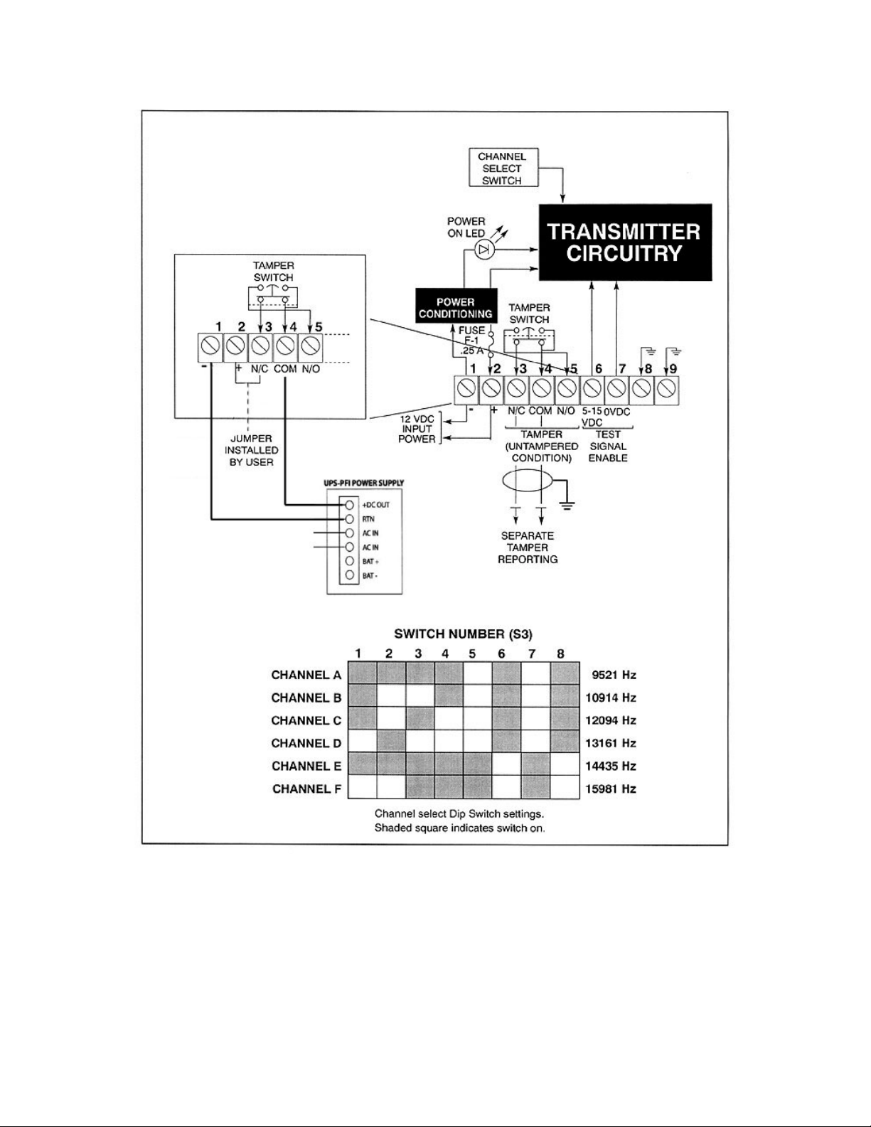
Figure 11: Transmi t t er Wir ing
14
Page 15

Specific Tamper Reporting
To have a specific tamper alarm report, wire the tamper reporting signal directly onto
Terminals 3 & 4 or 4 & 5. Use a twiste d/shielded pair of #18 wire for the tamper signal
wiring. This wire should be run from the dray contact tamper output terminals to the
junction box and onto the alarm reporting panel.
Alarm circuit
Terminals 6,7,8,9,10 and 11. There are two sets of normally open and normally c losed
relay contacts (dry); one set may be used for alarm annunciation at the a larm-reporting
panel. The other could be used for local annunciation, zone certification testing, etc. Use
a twisted/shielded pair of #18 wire to connect the alarm notification to the junction box
and alarm reporting panel.
Multipath Sidetone
Phono plug adjacent to Terminal 12. This is an audio output (2 milliwatts, 600 Ohm)
whose frequency and a mplitude are proportional to the amount and locations of a source
of motion within the detection zone. It can be used as a local test signal, or can be
amplified and connected to the alarm monitoring system. Shielded #18 audio wire should
be used to connect this signal to the annunciator.
OPERATING INSTRUCTIONS
Once the following preliminary checks, alignment and sensitivity adjustments are
accomplished, the PPi 24000 unit is ready to operat e. There are no controls or indicators
for operating the sensor system, and no alternate operating modes during emergency
conditions.
Preliminary Check
Once the sensor system is mounted and wiring installation completed, a preliminary
check, channel selection, and ante nna pattern selection is required before applying power
to the system.
Channel Select Switch
Refer to the Channel Selection Matrix Chart on the Receiver and Transmitter Wiring
Illustration. The channel select switch on each transmitter/receiver pair must be set to the
same operating channel.
Range Switch
This is a small jumper on the receiver circuit board located by the coax input from the
antenna . Put t his jumper in the “S” position for sepa ration distances of less the 100 feet;
use the “L” position for ranges greater than 100 feet.
15
Page 16

Latch/Timed Jumper
This is a white jumper wire located adjacent to terminals 9,10 & ll. On the receiver circuit
board. When the jumper is in the TIMED position, the setting of R76 DURATION
controls the alarm duration, whic h is user-adjustable betwee n .5 seconds and 10 seconds.
The LATCH position, once the system goes into alarm, it will stay in alarm until the
jumper is moved to the TIMED position. This jumper must be in the TIMED position for
normal operation; the LATCH position is used during electrical alignment of the system.
Sensitivity Jumper
The position of the Sensitivity Ju mper is determined by t he application re quirements. L
= Low Security, M = Mediu m Security and H = High Security. This jumper effectively
re duc es the max imum a lar m se ns itiv ity , pr ev ent ing e xce ssiv e se ns itiv it y th at may re sult
in nuisance alarms.
16
Page 17
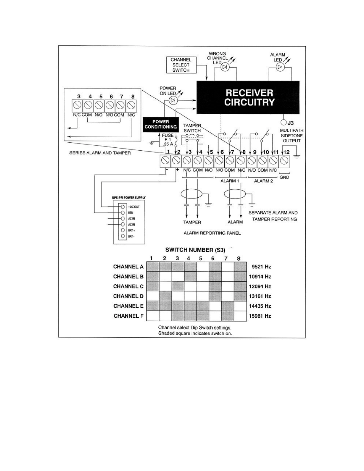
Figure 12: Receiver Wiring
17
Page 18

Antenna Pattern
The detect ion pattern is adjustable by use of the sensitivity adjustment and by cha nging
the configuration of the transmitting and receiving antenna. Installing RF a bs or b e nt p a d s
over selected antenna elements (see Figure 13) changes the antenna configuration. When
no antenna pads are installed, the microwave beam is narrowest (11 degrees). With eight
of the elements covered, the beam is 16 degrees, and with sixteen of the elements
covered, the pattern is 24 degrees. In general, the wide pattern should only be used when
the separation distance between receiver and transmitter is 50 feet or less. The med ium
range pattern should be used (if nec essary) with separation distances of betwee n 50 and
100 feet. The narrowest patte rn (unmodified antenna ) must be used when t he separation
distance is greater then 100 feet. Always use the narrowest beam possible commensurate
with detection requirements.
Install the absorbent pads on both the receiver and transmitter pair in accordance with the
fo llo w in g in st r uc t io n s :
1 Select the number of strips of double-backed tape that will cover the elements
necessary to provide the desired detection pattern. Remove the paper backing, and
stick he tape ove r the elements to be covered. Cover only the elements shown in the
illustration.
2 Remove the other piece of paper backing from the tape, and firmly press the RF
absorbent material to it.
3 Be sure that both the transmitting antenna and the receiving antenna configurations
are identical.
18
Page 19
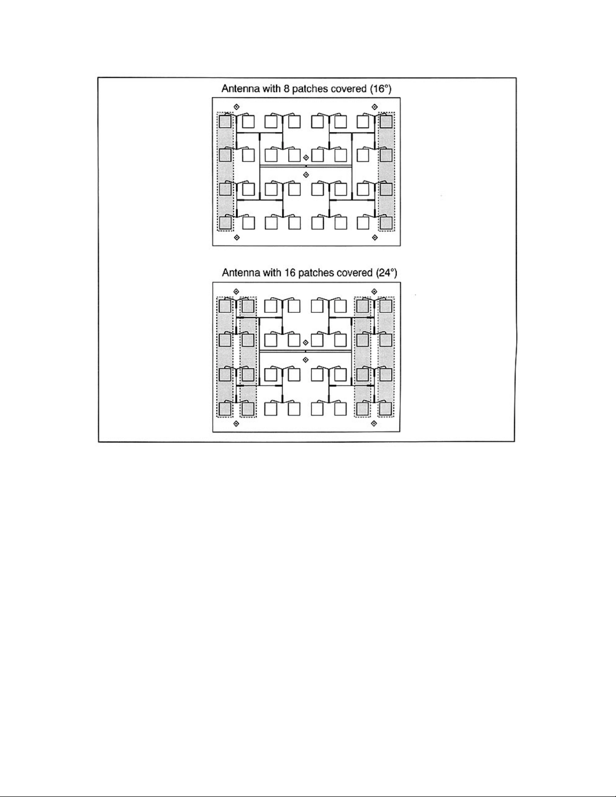
Figure 13: A nt enna C onf i gur at i o ns
ELECTRICAL ALIGNMENT
An electrical align ment requires the antennas of both the transmitter and receiver to be
looking head-to-he ad. Verify initial mechanical alignment. Once t his initial mechanical
alignment is done, a more precise electrical alignment is required. The
transmitter/receiver units should never be aimed into the ground or off to the side of the
detection zone. However, discontinuities in the detection zone may dictate an alignment
slightly off head-to-head.
NOTE:
receiver circuit board in the LATCHED position. This will speed up the response time of
the AGC voltage to make the adjustment easier.
During this alignment procedure, place the LATCH/TIMED jumper on the
19
Page 20

AGC Measurements
At the receiver, connect a digital voltmeter between TP-10 (+) and TB1-1 (-). This is the
automatic gain control (AGC) voltage, and, after final alignment as outlined below,
should be between 1.7 and 7.3 VDC. Put the SHORT-LONG jumper in the LONG
position to increase the AGC voltage and in the SHORT position to decrease the AGC
voltage.
Receiver
Slowly move the receiver unit up and down the post while monitoring the receiver unit
AGC voltage. Once a maximum AGC voltage is obtained, rotate the receiver until
maximum AGC is obtained on this axis. Tilt the receiver antenna up and down, again
ad ju st ing for ma x i mum A GC vo lt a ge .
Transmitter
Continue to monitor the AGC voltage at the receiver while moving the transmitter in all
three axes until maximum AGC voltage is obtained
Final Alignment
After securing hardware, repeat the transmitter and receiver unit electrical alignment
steps for obtaining maximum AGC reading on all the rotational axes.
Secure Hardware
Secure the mounting nuts and bolts. Ensure the AGC voltage remains high while this
hardware is ti ghtened. If the final AGC voltage is greater tha n 4.0 volts put the SHORTLONG ju mpe r in t he SHORT po sition; t his w i ll redu c e t he vo lta ge to th e 2.5 to 3.0 volt
ranges. Move the LATCHED-TIMED jumper to the TIMED position for normal alarm
operation.
SENSITIVITY ADJUSTMENT
Before beginning a sensitivity adjust ment, make sure the re ceiver “ALARM” LED is not
lit. Connect an ohmmeter between TB1 terminals 10 and 11; it will read less than 0.5
ohms when the system is operational (armed) and infinity when the unit is in alarm,
Leave the ohmmeter connected.
Alar m Test
A preliminary alarm test requires walking across the detection zone to ensure the unit
goes into alarm (“ ALARM LED” lit, ohmmeter to infinity). If it does not, adjust the
sensitivity potentiometer (R55) clockwise; then walk test the zone again. An alarm report
should nor mally occur before the walker breaks a line of sight between the transmitter
and receiver units.
20
Page 21

Final Alarm Test
Determine the level of sec urity sensitivity desired, and then use t he following parameters
for ensuring that the level desired is present.
NOTE:
unable to get the required detect ion with adjustment of R55 alone. The final a d justment
setting should be the lowest setting possible that provides the required detection.
Low security – walk across detection zone. Adjust R55 for consistent detection.
Medium security – crawl across detection zone on hands and knees. Adjust R55 for
consistent detection
High security – pu ll ba ll (see High Security); pull often enough to give confidence that
the zone has the sensitivity you want,
High Security
Adjustment for a typical high security application requires the detection of a prone
human crawling through the detection zone with the length of the body parallel to the line
of sight. A 13 inch (30.5cm) metal sphere repre sents approximately the same t arget to
the microwave sensor.
When adjusting the sensitivity to high security specifications slowly (5”/sec or faster)
pull the sphere t hrough the zone (perpendicular to the line of sight) a pproximately every
10 feet (3m) and adjust the sensitivity potentiometer R55 until repeatable detection is
obtained. Dragging the ball in the offset area is not necessary.
Start with the sensit ivity jumper in the “L” position – change to “M” or “H” if
THEORY OF OPERATION
Transmitter
Here is a functional block diagram of the transmitter unit for the model 24000.
21
Page 22
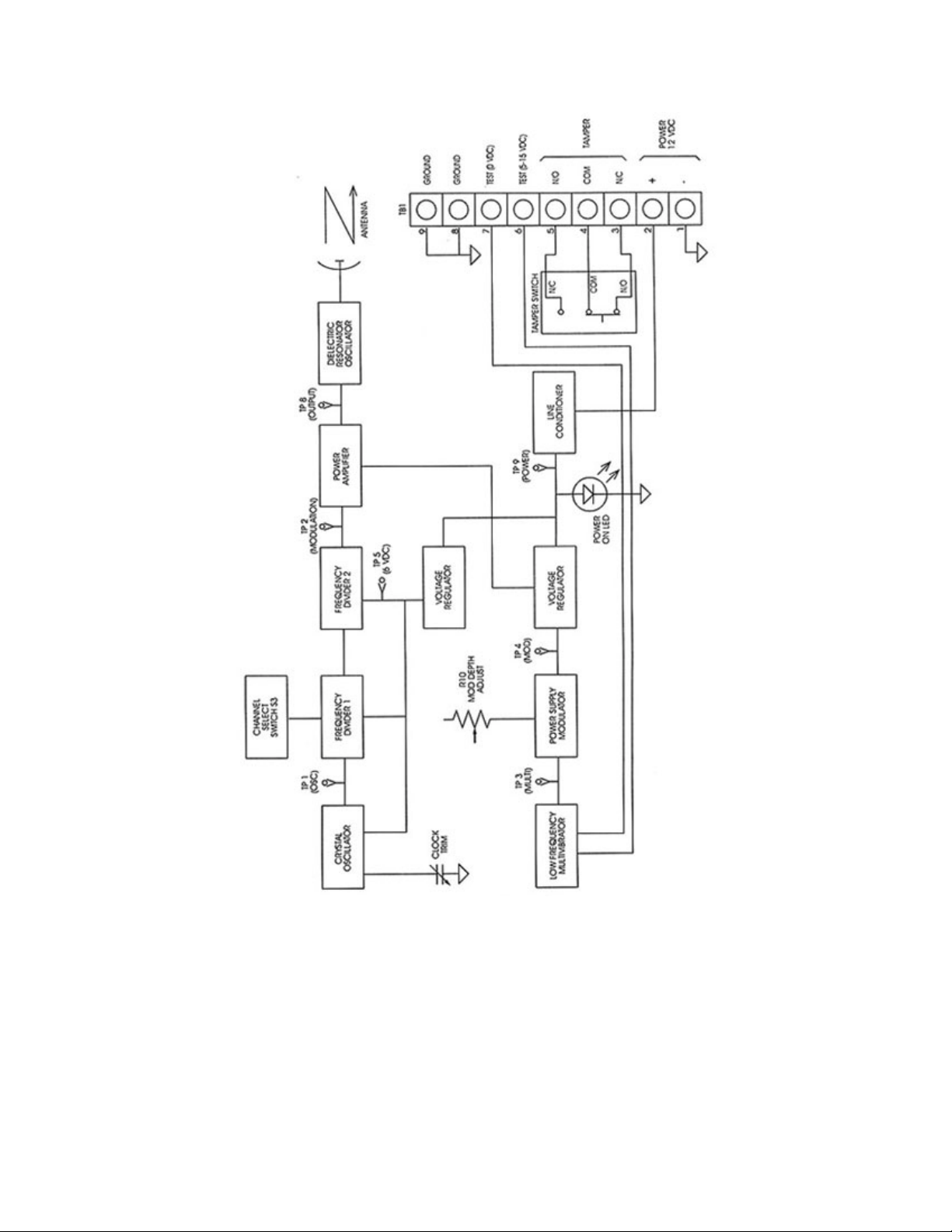
Figure 14: Transmitter Block D i agr am
Receiver
Here is a functional block diagram of the receiver unit for the model 24000.
22
Page 23
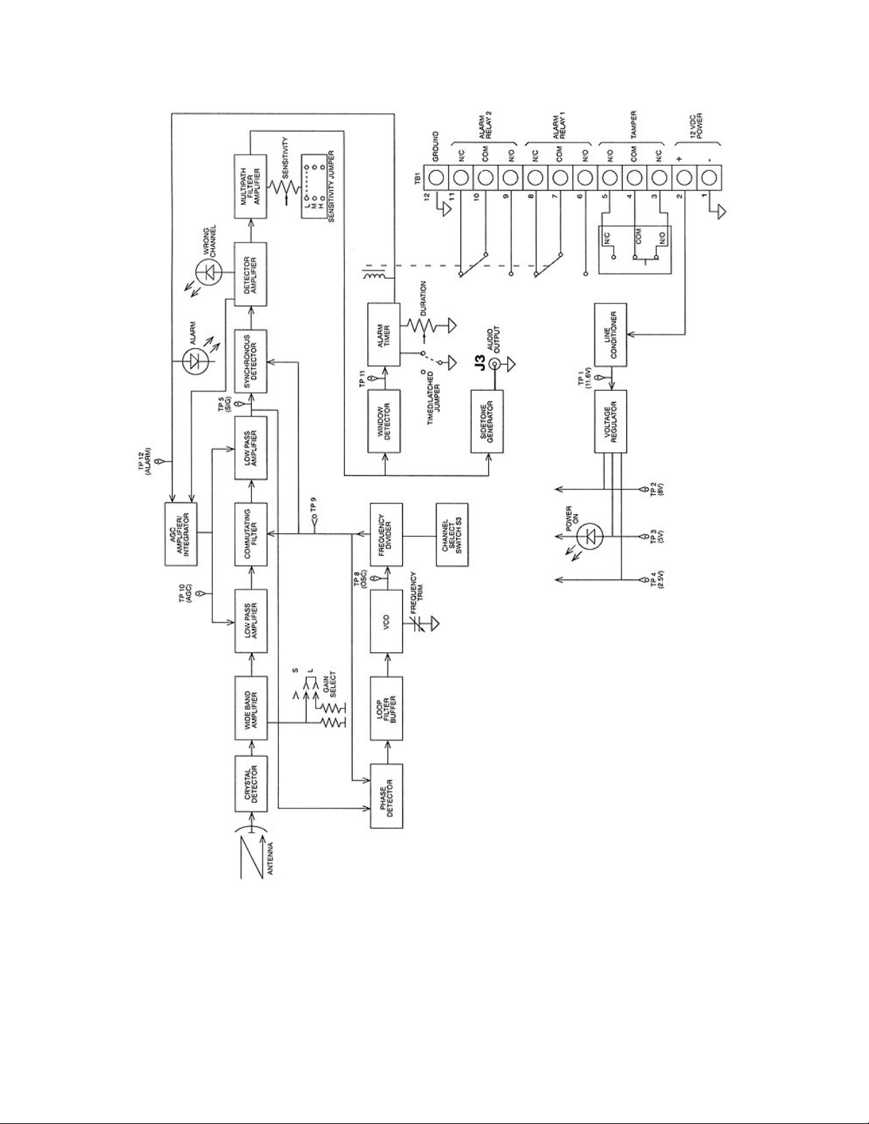
Figure 15: Recei ver Block Dia gram
23
Page 24

TROUBLESHOOTING
The following are procedures for troubleshooting the system. If, after che cking out these
conditions, you find your system is sti ll not functioning, then the possibility of a faulty
condition on another system on the premises beside the PPi 24000 System is very likely.
Nuisance Alarms
Nuisance alarms are usually attributed to physical problems within the detection zone.
Refer to the SITE PREPARATION section of the manual and review those conditions
inherent to ca using nuisance alarms. If these alarms persist, note time and c onditions of
each alarm. Is there a physical feature of your detection zone that occurs at certain
times, i.e., traffic or train going by, etc.?
Continuous Alarms
Continuous alarms are more apt to be an equipment-related problem than a detection
zone problem. First, determine if the sensor system is aligned and adjusted for
appropriate sensitivity. Refer to the OPERATING INSTRUCTIONS section of the
manual and review those conditions causing continuous alarms. Check to make sure t he
alarm relay latch-tined jumper is in the “Timed”(T) position. Remove external wires
from the receiver unit circuit board Terminal 6 or 8, and measure ohms on relay contact.
Then proceed to the BOARD LEVEL TEST POINTS section and test the
transmitter/receiver circuit boards.
An “a larm” situation may also occur if power to the system is bein g interrupted. Check
both the primary power source and all terminal connections for the DC power.
No Alarm
For a “no alarm” situation, check the alarm relay to verify it is working. Remove
external wires from the receiver unit circuit board Terminal 6 or 8, and measure ohms on
relay contact. Also check the receiver circuit board with the test points listed in the
BOARD LEVEL TEST POINTS section.
TEST POINTS
The board containing the electronic circuitry in the transmitter/receiver unit electronic
enclosures may be tested for readings required for normal operation of the system Figures
12 and 13 show the location of the te st points on the boards. This te st should be done
under the following conditions:
1 12 VDC (nominal) power applied to both transmitter and receiver units.
2 The same channel selection for both transmitter and receiver units
3 Mechanical (transmitter to receiver) alignment complete
4 Obtain “normal indications” for each test/observation before proceeding to the next
test point.
24
Page 25

5 Al l mea sur eme nts re quir e a d igit al mult ime te r (D MM) e xc ept whe re an osc illosc ope
reading is indicated.
25
Page 26
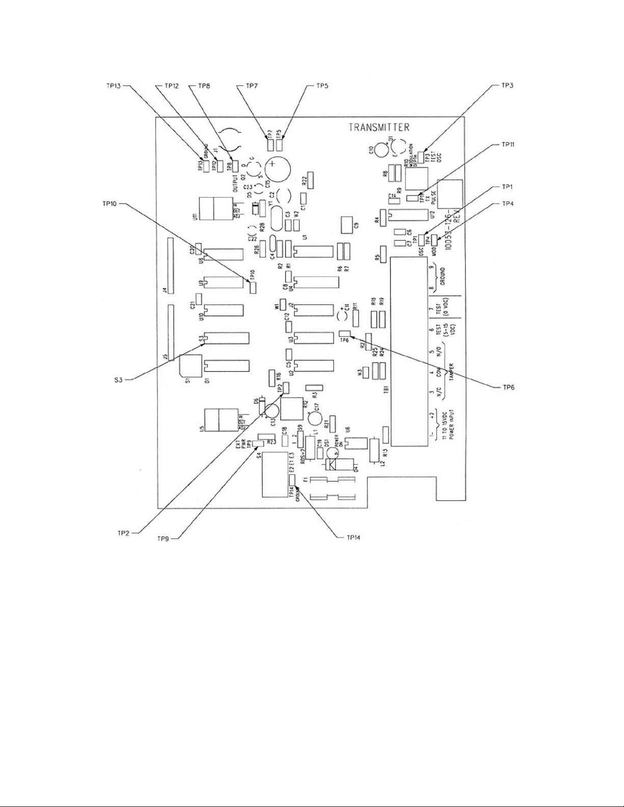
Figure 16: Transmitter Circuit Board Component Location
26
Page 27
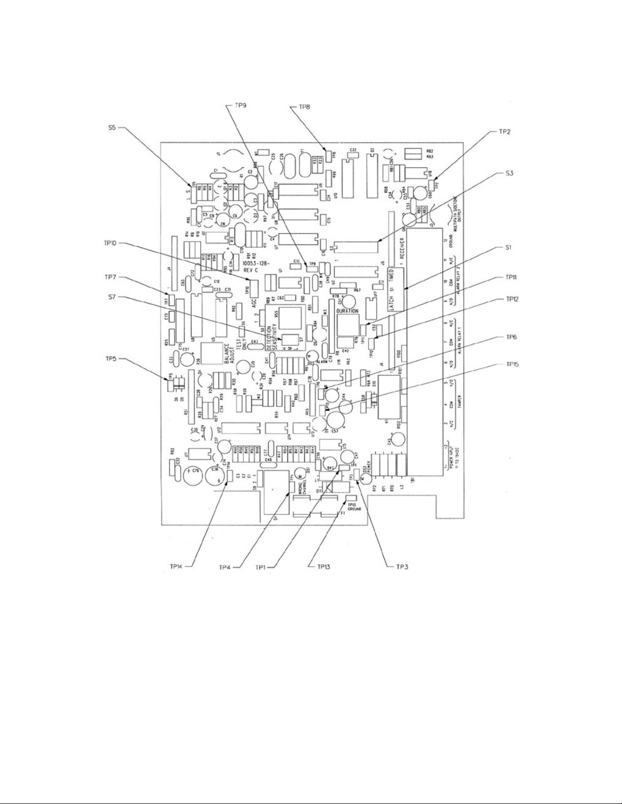
Figure 17: Receiver Circuit Board Component Location
27
 Loading...