


PERICOM PI74FCT2240TP, PI74FCT2240TQ, PI74FCT2240TR, PI74FCT2240TS, PI74FCT2241TH Datasheet
...
PI74FCT240T/241T/ 244T/540T/541T (25 ohmSeries)
PI74FCT2240T/2241T/2244T/2541T
234567890123456789012345678901212345678901234567890123456789012123456789012345678901234567890121234567890123456789012345678901 |
2123456789012 |
234567890123456789012345678901212345678901234567890123456789012123456789012345678901234567890121234567890123456789012345678901 |
2123456789012 |
ProductFeatures
•PI74FCT240/241/244/540/541TandPI74FCT2240/2241/2244/ 2541T are pin compatible with bipolar FAST™ Series at a higher speed and lower power consumption
•25Ω series resistor on all outputs (FCT2XXX only)
•TTL input and output levels
•Low ground bounce outputs
•Extremely low static power
•Hysteresis on all inputs
•Industrial operating temperature range: –40°C to +85°C
•Packages available:
–20-pin 173 mil wide plastic TSSOP (L)
–20-pin 209 mil wide plastic SSOP (H)
–20-pin 300 mil wide plastic DIP (P)
–20-pin 150 mil wide plastic QSOP (Q)
–20-pin 150 mil wide plastic TQSOP (R)
–20-pin 300 mil wide plastic SOIC (S)
•Device models available upon request
Fast CMOS Octal
Buffer/Line Drivers
ProductDescription
Pericom Semiconductor’s PI74FCT series of logic circuits are produced in the Company’s advanced 0.6/0.8 micron CMOS technology, achieving industry leading speed grades. All PI74FCT2XXX devices have a built-in 25 ohm series resistor on all outputs to reduce noise because of reflections, thus eliminating the need for an external terminating resistor.
The PI74FCT240T/241T/244T/540T/541T and P174FCT2240T/ 2241T/2244/2541T are 8-bit wide driver circuits, designed to be used in applications requiring high-speed and high-output drive. Ideal applications would include bus drivers, memory drivers, address drivers, and system clock drivers.
The PI74FCT540T and PI74FCT541/2541T provide similar driver capabilities, but have their pins physically grouped by function. All inputs are located on one side of the package, while outputs are on the opposite side, allowing for a much simpler and denser board layout.
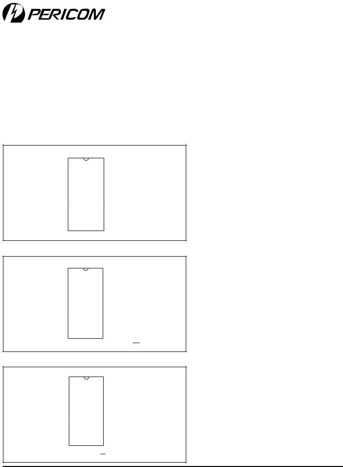
Logic Block Diagrams
PI74FCT240/2240T |
|
OEA |
|
|
OEB |
DA0 |
OA0 |
OB0 |
DB0 |
DA1 |
OA1 |
OB1 |
DB1 |
DA2 |
OA2 |
OB2 |
DB2 |
DA3 |
OA3 |
OB3 |
DB3 |
PI74FCT241/2241T |
PI74FCT540T |
|
PI74FCT244/2244T |
PI74FCT541/2541T |
|
|
OEA |
OEB |
OEA |
241 Only |
|
|
|
|
|
|
|
OEB* |
|
|
DA0 |
OA0 |
D0 |
O0 |
|
|
||
OB0 |
DB0 |
D1 |
O1 |
|
|
||
DA1 |
OA1 |
D2 |
O2 |
|
|
||
OB1 |
DB1 |
D3 |
O3 |
|
|
||
DA2 |
OA2 |
D4 |
O4 |
|
|
||
OB2 |
DB2 |
D5 |
O5 |
DA3 |
OA3 |
D6 |
O6 |
|
|
||
OB3 |
DB3 |
D7 |
O7 |
|
*OEB for 241T, *OEB for 244T, |
*Logic diagram shown for 540T. |
|
|
541/2541T is the non-inverting option. |
||
|
|
||
1 |
PS2011B |
12/11/00 |
PI74FCT240T/241T/244T/540T/541T(25ohmSeries)
PI74FCT2240T/2241T/2244T/2541T
OctalBuffer/LineDrivers
1234567890123456789012345678901212345678901234567890123456789012123456789012345678901234567890121234567890123456789012345678901 |
2123456789012 |
Product Pin Description
PinName |
Description |
||||
|
|
|
|
|
|
|
|
|
|
|
3-State Output Enable Inputs (Active LOW) |
OEA, OEB |
|||||
OEB(1) |
3-State Output Enable Input (Active HIGH) |
||||
Dxx |
Inputs |
||||
|
|
|
|
|
|
Oxx |
Outputs |
||||
|
|
|
|
|
|
GND |
Ground |
||||
|
|
|
|
|
|
VCC |
Power |
||||
|
|
|
|
|
|
Truth Table
|
|
|
|
Inputs(1) |
|
|
Outputs(1) |
|
|
||||
|
OE |
A |
|
OE |
B |
OEB(2) |
D |
240 |
241 |
244 |
|
540 |
541 |
|
L |
|
L |
H |
L |
H |
L |
L |
|
H |
L |
||
|
|
|
|
|
|
|
|
|
|
|
|
|
|
|
L |
|
L |
H |
H |
L |
H |
H |
|
L |
H |
||
|
|
|
|
|
|
|
|
|
|
|
|
|
|
|
H |
|
H |
L |
X |
Z |
Z |
Z |
|
Z |
Z |
||
|
|
|
|
|
|
|
|
|
|
|
|
|
|
Note:
1.H = High Voltage Level, X = Don't Care, L = Low Voltage Level, Z = High Impedance
2.OEB for 241 only.
PI74FCT240/2240T Product Pin Configuration
|
|
|
|
|
|
|
|
|
|
|
|
|
|
|
|
|
OEA |
|
1 |
|
20 |
|
Vcc |
||||||||||
|
|
|
||||||||||||||
|
DA0 |
|
|
|
|
|
|
|
|
|
|
|
B |
|||
|
|
2 |
20-Pin |
19 |
|
OE |
||||||||||
|
|
|||||||||||||||
OB0 |
|
|
|
|
|
|
|
|
|
0 |
||||||
|
3 |
18 |
|
OA |
||||||||||||
|
DA1 |
|
H20 |
17 |
|
DB0 |
||||||||||
|
4 |
|
||||||||||||||
|
|
1 |
|
L20 |
|
|
OA1 |
|||||||||
OB |
|
5 |
16 |
|
||||||||||||
|
|
|||||||||||||||
|
DA2 |
|
P20 |
15 |
|
DB1 |
||||||||||
|
6 |
|
||||||||||||||
|
|
2 |
|
Q20 |
|
|
|
|
|
2 |
||||||
OB |
|
7 |
14 |
|
OA |
|||||||||||
|
|
|||||||||||||||
|
DA3 |
|
8 |
R20 |
13 |
|
DB2 |
|||||||||
|
|
|||||||||||||||
|
|
|||||||||||||||
|
OB |
3 |
|
9 |
S20 |
12 |
|
|
OA |
3 |
||||||
|
|
|||||||||||||||
GND |
|
|
11 |
|
DB3 |
|||||||||||
|
10 |
|
|
|||||||||||||
|
|
|
||||||||||||||
PI74FCT241/2241/244/2244T Product Pin Configuration
|
|
|
|
|
|
|
|
|
|
|
OEA |
|
1 |
|
20 |
|
Vcc |
||||
|
|
|
||||||||
|
DA0 |
|
|
|
|
|
|
|
B |
|
|
|
2 |
|
19 |
|
OE |
||||
|
|
|
||||||||
OB0 |
|
3 |
20-Pin 18 |
|
OA0 |
|||||
|
|
|||||||||
|
DA1 |
|
4 |
H20 |
17 |
|
DB0 |
|||
|
|
|||||||||
|
|
|||||||||
OB1 |
|
5 |
L20 |
16 |
|
OA1 |
||||
|
|
|||||||||
|
DA2 |
|
6 |
P20 |
15 |
|
DB1 |
|||
|
|
|||||||||
OB2 |
|
7 |
Q20 |
14 |
|
OA2 |
||||
|
|
|||||||||
|
DA3 |
|
8 |
R20 |
13 |
|
DB2 |
|||
|
|
|||||||||
OB3 |
|
9 |
S20 |
12 |
|
OA3 |
||||
|
|
|||||||||
GND |
|
|
11 |
|
DB3 |
|||||
|
10 |
|
|
|||||||
|
|
|
||||||||
*OEB for 241T, OEB for 244T
PI74FCT540/541/2541T Product Pin Configuration
|
|
|
|
|
|
|
|
|
|
|
OEA |
|
1 |
|
20 |
|
Vcc |
||||
|
|
|
||||||||
|
D0 |
|
|
|
|
|
|
|||
|
|
2 |
|
19 |
|
|
OE |
B |
||
|
|
|
||||||||
|
D1 |
|
3 |
20-Pin 18 |
|
O0* |
||||
|
|
|||||||||
|
D2 |
|
H20 |
17 |
|
O2* |
||||
|
4 |
|
||||||||
|
D3 |
|
L20 |
16 |
|
O2* |
||||
|
5 |
|
||||||||
|
D4 |
|
P20 |
15 |
|
O3* |
||||
|
6 |
|
||||||||
|
|
|||||||||
|
D5 |
|
7 |
Q20 |
14 |
|
O4* |
|||
|
|
|||||||||
|
D6 |
|
8 |
R20 |
13 |
|
O5* |
|||
|
|
|||||||||
|
D7 |
|
9 |
S20 |
12 |
|
O6* |
|||
|
|
|||||||||
GND |
|
10 |
|
11 |
|
O7* |
||||
|
|
|
||||||||
*Ox for 540T, Ox for 541T
2 |
PS2011B |
12/11/00 |
 Loading...