

Peri MULTIPROP MP 120, MULTIPROP MP 250, MULTIPROP MP 350, MULTIPROP MP 480, MULTIPROP MP 625 Instructions For Assembly And Use

MULTIPROP MP 120, 250, 350, 480, 625
Slab Props
Edition 05 | 2015
Instructions for Assembly and Use – Standard Confi guration

Introduction
Overview, main components 1
Standard configuration 2
Intended use 2
Safety instructions 3
General 3
Standard configuration
A1 Assembly
Pre-assembling the slab prop 4
Assembly with Universal Tripod 6
A2 Dismantling
Releasing the slab prop under load 7
A3 Accessories
Brace Clamp 8
Base MP 50 9
A4 Foreseeable misapplications 10
A5 Storage and Transportation 13
Tables
Permissible prop loads
MULTIPROP MP 120, 250, 350, 480, 625 14
MULTIPROP MP 120, 250, 350, 480,
625 with Base MP 50 15
Components
Components 16
Instructions for Assembly and Use – Standard Configuration
MULTIPROP Slab Props
Content
Key
Safety instructions Note
Visual check
Tip
Load-bearing
point

1 Instructions for Assembly and Use – Standard Configuration
MULTIPROP Slab Props
Introduction
Overview, main components
MULTIPROP MP
1 Outer Tube
2 Inner Tube
3 Securing Hook
4 Adjusting Collar
5 Pressure Spring
6 Measuring Tape
7 Rubbing Plate
8 End Plate
Base MP 50
11 Base MP 50
11a Head Plate
11c Clamping Claw
11b Centering Pin
6
2
1
4
7
8
11
11a
11b
11c
8
5
3

2 Instructions for Assembly and Use – Standard Configuration
MULTIPROP Slab Props
Introduction
Area of application
MULTIPROP Slab Props
– are props made of aluminium,
– correspond to the load requirements
of DIN EN 1065,
– are used as vertical supports for tem-
porary constructions.
Standard configuration
Intended use
1. PERI products have been designed
for exclusive use in the industrial and
commercial sectors by suitably trained
personnel only.
2. These Instructions for Assembly and
Use serve as basis for the project-related risk assessment and the instructions
for the provision and use of the system
by the contractor (user). However, they
do not replace them.
3. Only PERI original components may
be used. The use of other products and
spare parts represents a misapplication
with associated safety risks.
4. The components are to be inspected
before each use to ensure that they are
in perfect condition and function correctly.
5. Changes to PERI components are
not permitted and represent a misapplication with associated safety risks.
6. Safety instructions and permissible
loads must be observed at all times.
7. Components provided by the contractor must correspond to the characteristic features required in these Instructions for Assembly and Use as well as
all current laws and standards.
In particular, the following applies if
nothing else is specified:
– timber components: Strength Class
C24 for Solid Wood EN 338.
– scaffold tubes: galvanised steel tubes
with minimum dimensions of Ø 48.3
x 3.2 mm according to EN 128111:2003 4.2.1.2.
– scaffold tube couplings according to
EN 74.
8. Deviations from the standard configuration may only be carried out after a
separate risk assessment has been
completed by the contractor (user).
On this basis, appropriate measures for
the working safety and stability are to
be implemented.
Main components
MULTIPROP
MP 120, L = 0.80 – 1.20 m
MP 250, L = 1.45 – 2.50 m
MP 350, L = 1.95 – 3.50 m
MP 480, L = 2.60 – 4.80 m
MP 625, L = 4.30 – 6.25 m
System dimensions
Assembly heights as individual props
according to the permissible extension
lengths 0.80 m – 6.25 m or 1.30 m –
6.75 m for use with Base MP 50.
Technical data
– Approval Z-8.312-824.
– For load-bearing capacities,
see Tables.
Features
MULTIPROP slab props are used in
shoring operations in a planned perpendicular position for the transfer of vertical loads. In particular, they also provide
support for slab formwork systems.
The outer tubes of the MULTIPROP
Slab Props are powder coated.
The integrated measuring tape and
free-running collar allow accurate and
fast height adjustment.
The height is continuously adjustable
by means of the end-to-end thread
without pegging. The MULTIPROP Slab
Prop has a fail-safe feature which prevents the inner tube from unintentionally slipping out.

3Instructions for Assembly and Use – Standard Configuration
MULTIPROP Slab Props
Introduction
Safety instructions
Brochure:
– MULTIPROP Aluminium Slab Props
Type tests for:
– MULTIPROP Props
– MULTIPROP System
– MULTIPROP Props with Base MP 50
– MULTIPROP System with Base MP 50
General
1. Deviations from the standard configuration and/or intended use present a
potential safety risk.
2. All country-specific laws, standards
and other safety regulations are to be
taken into account whenever our products are used.
3. During unfavourable weather conditions, suitable precautions and measures are to be taken in order to ensure
both working safety and stability.
4. The contractor (user) must ensure
the stability throughout all phases of
construction. He must ensure and verify that all occuring loads are safely
transferred.
5. The contractor (user) has to provide
safe working areas for site personnel
which can be reached through the provision of safe access means. Areas of
risk must be cordoned off and marked.
Hatches and openings on accessible
working areas must be kept closed during working operations.
6. For better comprehensibility, detailed
drawings are partly incomplete. The
safety installations which have possibly
not been included in these detailed
drawings must nevertheless still be
available.
System-specific
1. Retract components only when the
concrete has sufficiently hardened and
the person in charge has given the
approval for striking to take place.
2. Anchoring is to take place only if the
anchorage has sufficient concrete
strength.
3. After exceptional occurrences or long
periods of downtime at the location
where the formwork or shoring is used,
the unit and its components must be
checked for stability and functionality.
Care and maintenance
1. MULTIPROP Slab Props have been
designed for long-term use on the construction site.
2. In order to maintain the value and
operational readiness of the MULTIPROP
Slab Props over a long period of time,
the props should be carefully handled at
all times.
3. Occasionally grease the rubbing plate
to ensure easier handling.
4. Only PERI qualified personnel are
allowed to carry out repairs on the
MULTIPROP Slab Props.
Storage and transportation
1. Do not drop the components.
2. Store and transport components
ensuring that no unintentional change
in their position is possible. Detach lifting gear from the lowered units only if
these are in a stable position and no
unintentional change is possible.
3. When moving the components,
make sure they are lifted and set down
in a way that any unintentional tilting
over, falling apart, sliding or rolling away
is prevented.
4. Use only suitable load-carrying
equipment to move the components as
well as the designated load-bearing
points.
5. During the lifting and moving procedure, ensure that all loose parts are
removed or secured.
6. Assemble and move components on
clean, flat and sufficiently load-bearing
surfaces only.
General
The structures shown in these Instructions for Assembly and Use are examples and feature only one component
size. They are valid accordingly for all
component sizes contained in the
standard configuration.
Instructions for Use:
– Pallets and Stacking Devices
Instructions for Assembly and Use:
– MULTIFLEX
– SKYDECK
– TABLE MODULES / SLAB TABLES
– SKYTABLE
– VARIODECK
Additional PERI product information
PERI design tables

4 Instructions for Assembly and Use – Standard Configuration
MULTIPROP Slab Props
A1 Assembly
Pre-assembling the slab
prop
For the safety of the user, the
following should be checked before
every use to see whether
– the slab prop is complete,
– the slab prop has no cracks, holes
or broken parts,
– the inner tube and collar are freely
movable and
– the end plates are level.
– Shown here is the assembly of a
free-standing MULTIPROP Slab Prop.
– When used in the system, the
“MULTIPROP System” Instructions
for Assembly and Use must be
adhered to.
– The numbers on the integrated
measuring tape show the complete
length (L) of the MULTIPROP Slab
Prop in metres [m], e.g. 1
25 = 1.25 m.
– The complete length of the
MULTIPROP Slab Prop can be read
at the top edge of the collar (4a).
– Adjusting range per complete turn:
36 mm.
– The prop can be continuously
readjusted by means of the adjusting
collar if partially loaded up to 15 kN.
Preparation
MULTIPROP Slab Props are delivered
with retracted inner tubes in a Pallet
RP-2 as standard.
Place the prop on an available work
trestle or the Pallet RP-2.
(Fig. A1.01a + A1.01b)
Fig. A1.01a
Fig. A1.01b
5Instructions for Assembly and Use – Standard Configuration
MULTIPROP Slab Props
A1 Assembly
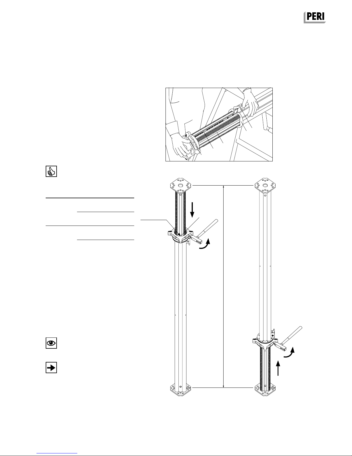
Fig. A1.02a
Inner tube bottom
Fig. A1.02c
4
6
2
3
7
adjusted
overall length
Position
Turn adjusting collar
“L” is:
Outer tube
bottom
(Fig. A1.02b)
anti-clockwise
smaller
anti-clockwise
larger
clockwise larger
clockwise smaller
Inner tube
bottom
(Fig. A1.02c)
L
Rough adjustment of the extension
length
1. Press down safety hook (3).
–> Inner tube (2) together with the
adjusting collar (4) is released.
(Fig. A1.02a)
2. Pull out inner tube until the length
indicated on the measuring tape (6) is
slightly more than the required prop
length.
3. Turn the adjusting collar until the
required extension length is reached.
4. Push in the inner tube until the
adjusting collar lies against the rubbing
plate (7).
–> Safety hook locks the inner tube in
position.
5. Fine adjustment of adjusting collar
(4) to specified length.
Is the safety hook engaged?
Quick adjustment of the smoothrunning adjusting collar is carried
out by “fast spindling“.
Outer tube bottom
Fig. A1.02b
4a

6
Instructions for Assembly and Use – Standard Configuration
MULTIPROP Slab Props
A1 Assembly
Assembly with Universal
Tripod
For slab props with tube Ø 48 mm to
Ø 120 mm.
Slab Props and Tripods
– place on clean, flat and sufficiently
load-bearing surface only!
– are not suitable for planned transfer
of horizontal loads!
– Shown here is the assembly of a
free-standing slab prop.
– When used in the system, the
respective Instructions for Assembly
and Use are to be taken into account.
– Universal Tripods (9) are pure assem-
bly aids for shuttering and striking up
to heights of approx. 3 m.
Universal Tripod assembly
1. Insert pre-assembled slab prop into
the Universal Tripod (9).
(Fig. A1.03)
2. Tighten clamp (9a).
Ensure that the slab prop lies flat
against the top and bottom connection
plates (9b and 9c).
(Fig. A1.03)
– Does the slab prop lie flat to the top
and bottom connection plates?
– Has the clamp been tightened?
– Is the slab prop in a perpendicular
position?
3
9a
Fig. A1.03
9c
9
9b

7Instructions for Assembly and Use – Standard Configuration
MULTIPROP Slab Props
Releasing the slab prop
under load
For loads > 60 kN, use the Wing Nut
Spanner HD!
Dismantling:
1. Release adjusting collar and set loadfree with:
– hammering the lowering cam.
(Fig. A2.01a)
– Wing Nut Spanner HD Item no.
022027. (Fig. A2.01b)
2. Remove slab prop.
3. Dismantle slab prop.
– Press down safety hook.
–> Inner tube with adjusting collar is
disengaged.
– Pull out inner tube a short distance
and spindle adjusting collar back to
the end plate.
– Push in the inner tube until the
adjusting collar lies against the rubbing plate.
–> Safety hook locks the inner tube in
position.
4. Place slab prop in the pallet.
See Section A5 “Storage and Transportation”.
The Wing Nut Spanner HD facilitates
energy-saving and noiseless loosening
of the adjusting collar – even if the
props are placed under maximum load.
Fig. A2.01a
Fig. A2.01b
A2 Dismantling
Outer tube bottom
Outer tube bottom

8
Instructions for Assembly and Use – Standard Configuration
MULTIPROP Slab Props
A3 Accessories
Fig. A3.01
10
Brace Clamp
Item no. 027790
Used as an alternative assembly aid
with high slab props as of approx. 4 m
using bracing boards 3 x 15 cm.
Brace Clamps are not suitable for a
planned transfer of horizontal loads!
– Brace Clamps (10) are simply assem-
bly aids for shuttering and striking
procedures.
– As an option, universal tripods can be
used as additional assembly aids.
Assembly
1. Pull the narrow side of the wedge
(10a) out of the clamp.
2. Place Brace Clamp (10) around the
tube of the slab prop.
3. Insert board in the open side of the
clamp.
4. Put wedge back into recess of the
clamp and hammer in securely.
–> The wedge secures the board.
5. Mount additional bracing boards by
means of Brace Clamps.
(Fig. A3.01)
– Are the slab props in a perpendicular
position?
– Are all wedges securely fixed?
– Have all wedges secured the boards?
10a

9Instructions for Assembly and Use – Standard Configuration
MULTIPROP Slab Props
A3 Accessories
Base MP 50
Take into account separate tables
with permissible prop load!
– Used for extending the slab prop by
50 cm.
– Automatic centering of the slab prop
by means of centering pins.
– Two clamping claws connect the
Base MP 50 with the slab prop.
– The MULTIPROP Slab Prop can be
mounted on the Base MP 50 with the
inner or outer tube.
Assembly
1. Place the slab prop on the head plate
(11a) of the Base MP 50 that the two
centering pins (11b) lock into the holes
of the end plate.
2. Position clamping claws (11c) with
the hammer on the end plate of the
slab prop. Base MP 50 (11) is now
connected to the prop. (Fig. A3.02)
Are the two clamping claws fully set on
the end plate?
Through the use of the Base MP 50,
the same type of prop can be used at
different heights.
Dismantling
Release clamping claws with a hammer.
Fig. A3.02
11b11a
11c
11

10
Instructions for Assembly and Use – Standard Configuration
MULTIPROP Slab Props
A4 Foreseeable misapplications
Applications of this type or similar are prohibited!
Ensure that slab props are always in
a perpendicular position!
Fig. A4.01
Non-loadable installation surface!
Fig. A4.03a
Only use full-faced support surfaces!
Fig. A4.02a Fig. A4.02b
Fig. A4.03b
Slab props must always be in a vertical
position.
End plates of the slab props must always lie completely flat.
If necessary, fill the gap and secure the wedge.
Slab props must always be positioned
on sufficiently load-bearing and flat surfaces.

11Instructions for Assembly and Use – Standard Configuration
MULTIPROP Slab Props
A4 Foreseeable misapplications
Do not use with Tilting Forkhead
MKK or Tilting Base MKF!
Fig. A4.05
Use designated support equipment,
e.g. Push-Pull Props or Brace Frames.
Do not use for supporting formwork
elements!
Fig. A4.06
If the clear height is too large, a longer
slab prop or shoring tower must be
used, e.g. MULTIPROP System with
MRK Frames.
Do not connect the slab props to
each other!
Fig. A4.04
Applications of this type or similar are prohibited!

12
Instructions for Assembly and Use – Standard Configuration
MULTIPROP Slab Props
A4 Foreseeable misapplications
Use designated trench strut.
Do not use as a trench strut!
Fig. A4.07
Do not use as anti-fall protection!
Use designated anti-fall protection, e.g.
PROKIT EP 110 or EP 200.
Fig. A4.08
Use designated anti-fall protection, e.g.
PROKIT EP 110 or EP 200.
Do not use as a guardrail holder!
Fig. A4.09
Applications of this type or similar are prohibited!

13Instructions for Assembly and Use – Standard Configuration
MULTIPROP Slab Props
– Instructions for Use for PERI Pallet
and Stacking Devices must be fol-
lowed at all times!
– Follow PERI packaging guidelines!
– Transportation units must be cor-
rectly stacked and secured!
PERI Pallets (14) are suitable for lifting
by a crane or forklift.
When using a crane, 4-sling lifting gear
is used to move the pallets.
During fork-lift operations, the pallets
can be moved either by a fork-lift truck
or by using the PERI Lifting Trolley. All
pallets can be lifted using the longitudinal as well as front sides.
Max. number of pallets in accordance
with packaging guidelines.
The safety hook (3) prevents the inner
tube (2) from slipping out and must be
engaged.
Storage
Store and transport slab props of the
same size! (Fig. A5.01 + A5.02)
Transportation
– Ensure loads are correctly secured
during transport!
– Use tension belts or steel bands.
The number of pallets that can be
transported depends on the respective
national transport regulations.
Fig. A5.01
Fig. A5.02
Example: MULTIPROP Slab Props
stacked using battens and secured by
means of a steel band.
2
3
Example: MULTIPROP Slab Props
positioned horizontally in a Pallet RP-2
and secured by means of a tension belt.
A5 Storage and Transportation

14
MP 250
L = 1.45 – 2.50 m
MP 350
L = 1.95 – 3.50 m
MP 480
L = 2.60 – 4.80 m
MP 625
L = 4.30 – 6.25 m
1.45 75.5 78.5
1.50 75.5 78.5
1.60 75.5 78.5
1.70 75.5 78.5
1.80 73.8 78.5
1.90 70.6 78.5
1.95 68.0 78.5 91.0 90.1
2.00 67.3 78.5 91.0 90.1
2.10 65.7 76.8 86.0 90.1
2.20 64.1 75.1 80.6 90.1
2.30 62.5 72.6 75.1 89.8
2.40 60.8 69.1 70.7 87.9
2.50 59.2 65.6 66.4 86.1
2.60 63.7 83.1 88.5 73.6
2.70 61.1 80.1 83.7 73.3
2.80 59.2 77.1 78.8 72.9
2.90 57.4 74.1 74.0 72.6
3.00 56.0 70.3 69.1 72.2
3.10 54.5 66.6 64.9 71.4
3.20 52.9 61.8 60.7 70.7
3.30 51.3 57.1 56.5 70.0
3.40 47.7 51.7 54.1 68.2
3.50 44.2 46.4 51.8 66.5
3.60 49.4 64.7
3.70 47.5 60.4
3.80 45.7 56.1
3.90 43.8 51.8
4.00 41.8 48.4
4.10 39.7 45.0
4.20 37.7 41.6
4.30 35.8 39.3 57.9 45.7
4.40 33.9 37.0 56.3 45.7
4.50 32.0 34.8 54.7 45.7
4.60 30.2 32.5 52.5 45.1
4.70 28.3 30.2 50.3 44.4
4.80 26.4 27.9 47.9 43.5
4.90 45.2 42.4
5.00 42.5 41.3
5.10 39.9 39.9
5.20 37.2 38.5
5.30 34.9 37.1
5.40 32.8 35.6
5.50 30.8 34.1
5.60 29.3 32.6
5.70 27.8 31.2
5.80 26.4 29.6
5.90 25.1 27.9
6.00 23.8 26.2
6.10 22.7 24.8
6.20 21.6 23.4
6.25 21.0 22.7
Instructions for Assembly and Use – Standard Configuration
MULTIPROP Slab Props
Table for MULTIPROP 250, 350, 480, 625
Permissible prop load [kN] according to the type test
Extension
length [m]
Outer tube
bottom
Inner tube
bottom
Outer tube
bottom
Inner tube
bottom
Outer tube
bottom
Inner tube
bottom
Outer tube
bottom
Inner tube
bottom
MULTIPROP Props are classified according to official approval as follows:
MP 250 = Class T 25
MP 350 = Class R 35
MP 480 = Class D 45
MP 625 = Class D 60
Note:
To release the loads > 60 kN we recommend using the HD Wingnut Spanner,
Item no. 022027.
When using PERI slab tables, the permissible load on the MULTIPROP MP 350
Prop is a minimum of 56 kN and a minimum of 36 kN for the MULTIPROP MP
480 over the entire extension length – this is due to the props being clamped in
the Table Swivel Head or UNIPORTAL Head.

15
MP 250 + MP 50
L = 1.95 – 3.00 m
MP 350 + MP 50
L = 2.45 – 4.00 m
MP 480 + MP 50
L = 3.10 – 5.30 m
MP 625 + MP 50
L = 4.80 – 6.75 m
2.25 76.6 73.6
2.30 74.5 72.9
2.40 72.4 72.1
2.50 66.1 69.8 87.6 84.2
2.60 63.3 67.7 83.8 82.9
2.70 60.5 65.6 79.9 81.7
2.80 57.7 63.1 76.1 80.5
2.90 55.1 60.1 70.0 77.0
3.00 52.4 57.1 63.9 73.5
3.10 60.8 70.6 76.8 73.3
3.20 57.6 67.6 74.4 72.8
3.30 55.2 64.7 71.9 72.3
3.40 52.7 61.8 69.4 71.8
3.50 50.8 59.1 67.0 71.3
3.60 48.8 56.4 62.6 70.0
3.70 46.9 52.2 58.2 68.7
3.80 45.0 48.0 53.9 67.4
3.90 41.8 43.9 51.2 62.9
4.00 38.5 39.8 48.6 58.4
4.10 45.9 53.9
4.20 43.9 50.1
4.30 41.9 46.3
4.40 39.8 42.5
4.50 37.7 40.0
4.60 35.5 37.5
4.70 33.3 35.0
4.80 31.7 33.2 48.7 44.5
4.90 30.0 31.4 47.5 44.4
5.00 28.4 29.6 46.2 44.3
5.10 26.7 27.8 44.5 43.1
5.20 25.1 26.0 42.8 41.8
5.30 23.4 24.2 41.1 40.4
5.40 40.1 39.6
5.50 37.3 37.2
5.60 35.3 35.6
5.70 33.3 34.0
5.80 31.5 32.5
5.90 30.6 31.7
6.00 28.1 29.5
6.10 26.7 28.1
6.20 25.3 26.7
6.30 24.1 25.4
6.40 23.5 24.8
6.50 21.8 22.9
6.60 20.8 21.7
6.70 19.8 20.6
6.75 19.3 20.0
Instructions for Assembly and Use – Standard Configuration
MULTIPROP Slab Props
Table for MULTIPROP 250, 350, 480, 625
with Base MP 50
Permissible prop load [kN] according to the type test
Overall height
[m]
(prop extension
+ 50 cm)
Outer tube
bottom
Inner tube
bottom
Outer tube
bottom
Inner tube
bottom
Outer tube
bottom
Inner tube
bottom
Outer tube
bottom
Inner tube
bottom
Note:
To release the loads > 60 kN we recommend using the HD Wingnut Spanner,
Item no. 022027.

MULTIPROP Slab Props
16
Item no. Weight kg
028000 9.170 Universal Tripod, galv.
Erection aid for slab props with Ø 48 – 120 mm
and 120 x 120 mm. Can also be used in combination with MULTIPROP MP slab props and all slab
props with Base MP 50.
Note
Only use as erection aid!
5
5
5
8
0
0
027288
027289
027290
027291
027305
10.200
15.400
19.500
24.900
34.700
MULTIPROP MP
MULTIPROP MP 120
MULTIPROP MP 250
MULTIPROP MP 350
MULTIPROP MP 480
MULTIPROP MP 625
Slab prop made of aluminium. Used as individual
prop as well as in combination with MULTIPROP
Frames MRK to form towers.
min. L max. L
800 1200
1450 2500
1950 3500
2600 4800
4300 6250
Note
Approved by the German Building Authorities No.
Z-8.312-824.
Technical Data
Permissible load: see PERI Design Tables.
1
0
1
0
m
i
n
L
m
a
x
L
150
648
0
1
2
0
Ø40
Ø14
100
8
7

MULTIPROP Slab Props
17
Item no. Weight kg
027310 8.900 Base MP 50
For use with slab props with an end plate thickness of 6 – 10 mm. With clamped quick-release
fastener.
Note
Permissible load: see PERI Design Tables.
5
0
0
89Ø
2
0
0
150
8
0
Ø12,5Ø42
022027 3.600 Wing Nut Spanner HD
For easy release of the Head Spindle HDK 45, the
Head Spindle TR 110-80/55 and the MULTIPROP
slab prop.
983
Ø38
027790 2.460 Brace Clamp HL, galv., 76 – 120 mm
For assembly of 3 x 15 cm stiffening boards at
slab props Ø 76 – 89 mm and 100 x 100 mm to
120 x 120 mm.
210
2
3
9
40450

MULTIPROP Slab Props
18
Item no. Weight kg
103434
103429
38.500
45.300
Pallets RP-2, galv.
Pallet RP-2 80 x 120, galv.
Pallet RP-2 80 x 150, galv.
For stacking and transportation of formwork and
scaffolding components.
Note
Follow Instructions for Use!
Technical Data
Permissible load-bearing capacity 1.5 t.
1200 / 1500
1080 / 1380
8
5
3
6
0
0
1
0
0
800
680

19

DE en 04 | 2016 3sm 793297 © PERI GmbH
The optimal System for every
Project and every Requirement
PERI GmbH
Formwork Scaffolding Engineering
Rudolf-Diesel-Strasse 19
89264 Weissenhorn
Germany
Tel. +49 (0)7309.950-0
Fax +49 (0)7309.951-0
info@peri.com
www.peri.com
System-Independent Accessories
Wall Formwork
Column Formwork
Slab Formwork
Climbing Systems
Tunnel Formwork Bridge Formwork
Shoring Systems
Facade ScaffoldConstruction Scaffold Industrial Scaffold
Access
Protection Scaffold Services
 Loading...