

Page 1
OPERATING MANUAL
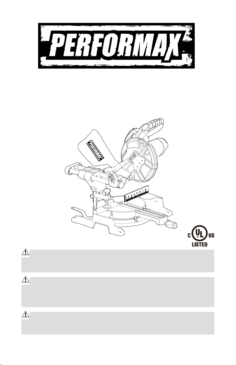
Sliding Compound Miter Saw
240-3687
IMPORTANT:
Read through this operating manual carefully before using this tool. Pay close
attention to all Safety Instructions, Warnings, and Caution sections. Use this
tool properly, and only for its intended use.
Safety symbols in this Manual are used to call attention to possible dangers.
The safety symbols and their explanations require the operator’s full understanding. The safety warnings do not, by themselves, eliminate any danger, and they
are not a substitute for proper accident-prevention measures.
This Safety Alert Symbol indicates caution, warning, or danger. Failure to obey
a safety warning can result in serious injury to the operator or to others. To reduce
the risk of injury, fire, or electric shock, always follow the safety precautions.
Page 2

TABLE OF CONTENTS
Rules for Safe Operation…………..……………………………….........Page 3
Description…………..…………………………………………............Page 10
Assembly…………..…………………………………………........... . . . Page11
Adjustments…………..………………………………………….........Page 13
Operation…………..…………………………………………..............Page 14
Maintenance…………..……………………………………….............Page 23
Troubleshooting…………..…………………………………….............Page 23
Accessories…………..…………………………………….................. Page 24
Warranty…………..……………………………………………...........Page 25
SPECIFICATIONS
Miter Saw Specifications:
Model: 240-3687
Motor: 120V~60Hz, 15A
Speed: 5500 RPM, no load
Blade: 10˝ (25.4 cm) (40-tooth) carbide-tipped
Laser: CLASS llla
Laser wavelength: 650 nm
Laser max outpower: ≤ 2.5 mW
sliding length: 8 1/4”
Weight: 38 lb 9 oz (17.5 kg)
Cutting capacity: 3-1/8 x 11-5/8" crosscut at 0° miter, 0° bevel
3-1/8 x 8" miter at 45° miter, 0° bevel
1-1/2 x 11-5/8" bevel at 0° miter, 45° bevel
1-1/2 x 8" compound at 45° miter, 45° bevel
2
Page 3

RULES FOR SAFE OPERATION
KNOW THE TOOL
To operate this tool safely, carefully read this Owner’s Manual and all labels
affixed to the Compound Miter Saw before using it, and follow all instructions
contained therein. Keep this Manual for future reference.
IMPORTANT
This tool should only be serviced by a qualified service technician.
READ ALL INSTRUCTIONS THOROUGHLY
GENERAL SAFETY RULES FOR BENCH TOOLS
WARNING! Read and understand all instructions. Failure to follow all
instructions listed below may result in electric shock, fire and/or serious
personal injury.
KEEP GUARDS IN PLACE and in working order.
REMOVE ADJUSTING KEYS AND WRENCHES. Form habit of checking to see
that keys and adjusting wrenches are removed from tool before turning it on.
KEEP WORK AREA CLEAN. Cluttered areas and benches invite accidents.
DON’T USE IN DANGEROUS ENVIRONMENT. Don’t use power tools in damp
or wet locations, or expose them to rain. Keep work area well lighted.
KEEP CHILDREN AWAY. All visitors should be kept safe distance from work
area.
MAKE WORKSHOP KID PROOF with padlocks master switches, or by
removing starter keys.
DON’T FORCE TOOL It will do the job better and safer at the rate for which it
was designed.
USE RIGHT TOOL Don’t force tool or attachment to do a job for which it was
not designed.
USE PROPER EXTENSION CORD. Make sure your extension cord is in good
condition. When using an extension cord, be sure to use one heavy enough
to carry the current your product will draw. An undersized cord will cause a
drop in line voltage resulting in loss of power and overheating. Table 1 shows
the correct size to use depending on cord length and nameplate ampere
rating. If in doubt, use the next heavier gage. The smaller the gage number,
the heavier the cord.
3
Page 4

Recommended size of extension cords
Total length of cord in feet
Tool’s Ampere rating Volts
0-6
6-10 18 16 14 12
10-12 16 16 14 12
12-16 14 12 Not Recommended
WEAR PROPER APPAREL Do not wear loose clothing, gloves, neckties, rings,
bracelets, or other jewelry which may get caught in moving parts. Nonslip
footwear is recommended. Wear protective hair covering to contain long hair.
ALWAYS USE SAFETY GLASSES. Also use face or dust mask if cutting
operation is dusty. Everyday eyeglasses only have impact resistant lenses,
they are NOT safety glasses.
SECURE WORK. Use clamps or a vise to hold work when practical. It’s safer
than using your hand and it frees both hands to operate tool.
DON’T OVERREACH. Keep proper footing and balance at all times.
MAINTAIN TOOLS WITH CARE. Keep tools sharp and clean for best and
safest performance. Follow instructions for lubricating and changing
accessories.
DISCONNECT TOOLS before servicing; when changing accessories, such as
blades, bits, cutters, and the like.
REDUCE THE RISK OF UNINTENTIONAL STARTING. Make sure switch is in
off position before plugging in.
USE RECOMMENDED ACCESSORIES. Consult the owner’s manual for
recommended accessories. The use of improper accessories may cause risk
of injury to persons.
NEVER STAND ON TOOL. Serious injury could occur if the tool is tipped or if
the cutting tool is unintentionally contacted.
CHECK DAMAGED PARTS. Before further use of the tool, a guard or other
part that is damaged should be carefully checked to determine that it will
operate properly and perform its intended function-check for alignment of
moving parts, binding of moving parts, breakage of parts, mounting, and any
other conditions that may affect its operation, A guard or other part that is
damaged should be properly repaired or replaced.
DIRECTION OF FEED. Feed work into a blade or cutter against the direction
of rotation of the blade or cutter only.
120
V~
Cord size in A. W. G.(minimum)
25’ 50’ 100’ 150’
18 16 16 14
4
Page 5
NEVER LEAVE TOOL RUNNING UNATTENDED. TURN POWER OFF. Don’t leave
tool until it comes to a complete stop.
ELECTRICAL SAFETY
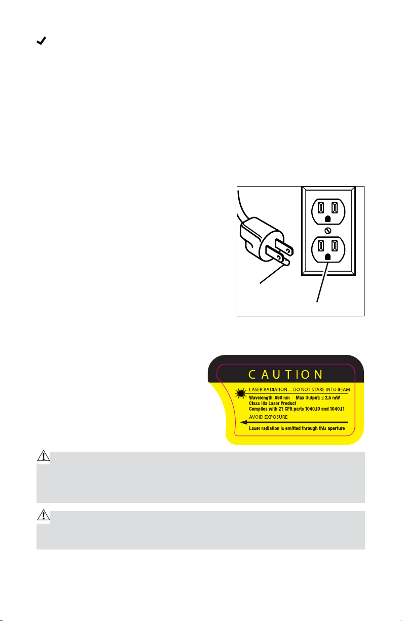
Grounding instruction: In the event of a malfunction or breakdown, grounding
provides a path of least resistance for electric current that reduces the risk
of electric shock. This tool is equipped with an electric cord that has an
equipment-grounding conductor and a grounding plug. The plug must be
plugged into a matching outlet that is properly installed and grounded, in
accordance with all local codes and ordinances.
Do not modify the plug provided. If it will not fit
the outlet, have a proper outlet installed by a
qualified electrician.
Use only 3-wired extension cords that have
3-pronged grounding plugs and 3-holed
receptacles that accept the tool’s plug.
Permanently connected tools: This tool should
be connected to a grounded metal permanent
wiring system or to a system that has an
equipment-grounding conductor.
Grounding
pin
120V Grounded outlet
SAFETY PRECAUTIONS FOR LASERS
This miter saw has a built-in laser
light. The laser is a Class IIla and emits
output power of a maximum 2.5mW and
650nm wavelengths. These lasers do
not normally present an optical hazard.
However, DO NOT stare at the beam as
this can cause flash blindness.
CAUTION: The following label is on your tool. It indicates where the saw
emits the laser light. BE AWARE of the laser light location when using. ALWAYS MAKE SURE that any bystanders in the vicinity of use are made aware
of the dangers of looking directly into the laser.
WARNING: LASER LIGHT. LASER RADIATION. Avoid Direct Eye Exposure.
DO NOT stare into beam. Only turn laser beam on when the saw is on the
workpiece.
5
Page 6

WARNING: Use of controls, adjustments or performance of procedures
other than those specified in this manual may result in hazardous radiation
exposure.
WARNING: Use of controls, adjustments or performance of procedures
other than those specified in this manual may result in hazardous radiation
exposure.
WARNING: The use of optical instruments such as, but not limited to,
telescopes or transits to view the laser beam will increase eye hazard.
The laser shall be used and maintained in accordance with the
manufacture’s instruction.
Never aim the beam at any person or an object other than the work piece.
Always ensure the laser beam is aimed at a sturdy work piece without
reflective surface. I.e. wood or rough coated surface are acceptable. Bright
shiny reflective sheet or the like is not suitable for laser use as the reflective
surface could direct the beam back at the operator.
Do not attempt to activate the laser when the tool housing is removed.
The laser is activated by means a button switch independent with the main
switch of the saw.
Do not change the laser light assembly with a different type. Any repairs
must only be carried out by the laser manufacture or authorized service
agent.
Do not attempt to repairs the laser guide by yourself.
Do not attempt to change any parts of the laser guide.
SPECIFIC SAFETY RULES FOR MITER SAW
ALWAYS wear eye protection.
DO NOT operate saw without guards in place.
BE SURE turn off tool and wait for saw blade to stop before moving
workpiece or changing settings.
BE SURE disconnecting power before changing blade or servicing.
DO NOT expose to rain or use in damp location.
WHEN SERVICING, use only identical replacement parts.
ALWAYS firmly clamp or bolt your miter saw to a secure, stable workbench
or table at approximately hip height.
BE SURE that all adjustments are secure BEFORE making a cut.
6
Page 7

ALWAYS make sure that the miter table and saw arm (bevel function) are
locked in position BEFORE operating your saw. Lock the miter table by
securely tightening the miter lock lever. Lock the saw arm (bevel function)
by securely tightening the bevel lock knob.
BE SURE that the blade path is free of nails. ALWAYS carefully inspect
lumber and remove all nails BEFORE cutting.
ALWAYS be sure that the blade clears the workpiece. NEVER start the saw
with the blade touching the workpiece. ALWAYS allow the motor to come
up to full speed BEFORE starting a cut.
SUPPORT long workpiece when cutting to minimize the risk of blade
pinching or kickback. The saw may slip, walk or slide while cutting long or
heavy boards.
NEVER use a length-stop on the free (scrap end) of a clamped workpiece,
NEVER hold onto or bind the free scrap end of the workpiece in any
operation. If work clamp and length stop are used together, THEY MUST
BOTH BE INSTALLED on the SAME SIDE of the saw table to prevent the
saw from catching the loose end and kicking up.
NEVER cut more than one piece at a time. DO NOT STACK more than one
workpiece on the worktable at a time.
AVOID awkward operations and hand positions where a sudden slip could
cause your hand to move into the blade. ALWAYS make sure that you
have good balance. NEVER operate your saw on the floor or in a crouched
position.
ONLY USE the correct blades. Use the right blade size, style and cutting
speed for the material and the type of cut. DO NOT use blades with
incorrect size holes. NEVER use blade washers or blade bolts that are
defective or incorrect. The maximum blade capacity for this saw is
10-inches.
ALWAYS keep blades clean, sharp and with the sufficient set. Sharp blades
minimize stalling and kickback.
DO NOT use dull or damaged blades. Bent blades can break easily, or cause
kickback.
DO NOT remove the saw’s blade guards. NEVER operate the saw with any
guard or cover removed. MAKE SURE that all guards are operating properly
BEFORE each use.
NEVER hand holds a workpiece that is too small to be clamped. ALWAYS
keep your hands clear of the “no hands” zone.
NEVER perform any operation freehand. ALWAYS place the workpiece to
be cut on the miter saw table and position it firmly against the fence as a
7
Page 8

backstop. ALWAYS use the fence.
NEVER apply lubricants to the blade when it is running. NEVER use
solvents to clean plastic parts. Solvents could possibly dissolve or
otherwise damage the material.
KEEP HAND OUT OF SAW BLADE. DO NOT reach under the material being
cut or in the blade’s cutting path with your fingers or hand for any reason.
DO NOT turn the motor switch on and off rapidly. This could cause the blade
to loosen, which could create a hazard. Should this ever occur, stand clear
and allow the saw blade to come to a complete stop. Disconnect the saw
from the power source and securely tighten the blade bolt.
ALWAYS turn off the saw before disconnecting it to avoid accidental
starting when reconnecting the saw to a power supply. NEVER leave the
saw unattended while connected to a power supply.
KEEP THE MOTOR AIR SLOTS clean and free of chips or dust. To avoid
motor damage, the motor should be blown out or vacuumed frequently to
keep sawdust from interfering with the motor ventilation.
NEVER lift this tool by gripping the cutting handle or the miter fence. This
may cause misalignment. ALWAYS carry saw by holding the base or carry
by the support bracket/carrying handle after you have locked the saw arm
in the “DOWN” position.
ADDITIONAL RULES FOR SAFE OPERATION
WARNING: Use of this tool can generate and/or disburse dust, which
may cause serious and permanent respiratory or other injury. Always
use NIOSH/OSHA approved respiratory protection appropriate for the dust
exposure. Direct particles away from face and body.
Know your power tool. Read operator’s manual carefully. Learn the
applications and limitations, as well as the specific potential hazards
related to this tool. Following this rule will reduce the risk of electric shock,
fire or serious injury.
ALWAYS wear safety glasses or eye shields when using this saw. Everyday
eyeglasses have only impact-resistant lenses; they are NOT safety glasses.
All users and bystanders MUST wear eye protection that conforms to ANSI
Z87.1
PROTECT your lungs. Wear a face mask or dust mask if the operation is
dusty.
PROTECT your hearing. Wear appropriate personal hearing protection
during use. Under some conditions and duration of use, noise from this
8
Page 9

product may contribute to hearing loss.
ALL VISTORS AND BYSTANDERS MUST wear the same safety equipment
that the operator of the saw wears.
INSPECT the tool cords periodically and if damaged have it repaired by
qualified person.
ALWAYS check the tool for damaged parts. Before further use of the tool, a
guard or other part that is damaged should be carefully checked to determine
if it will operate properly and perform its intended function. Check for
misalignment or binding of moving parts, breakage of parts, and any other
condition that may affect the tool’s operation. A guard or other part that is
damaged should be properly repaired or replaced by qualified person.
INSPECT and remove all nails from lumber before sawing.
SAVE THESE INSTRUCTIONS. Refer to them frequently and use them to
instruct others who may use this tool. If someone borrows this tool, make
sure they have these instructions also.
9
Page 10
DESCRIPTION
Dust Bag
Dust Bag Adaptor
Blade Wrench
Saw Blade
Shop Vacuum Adaptor
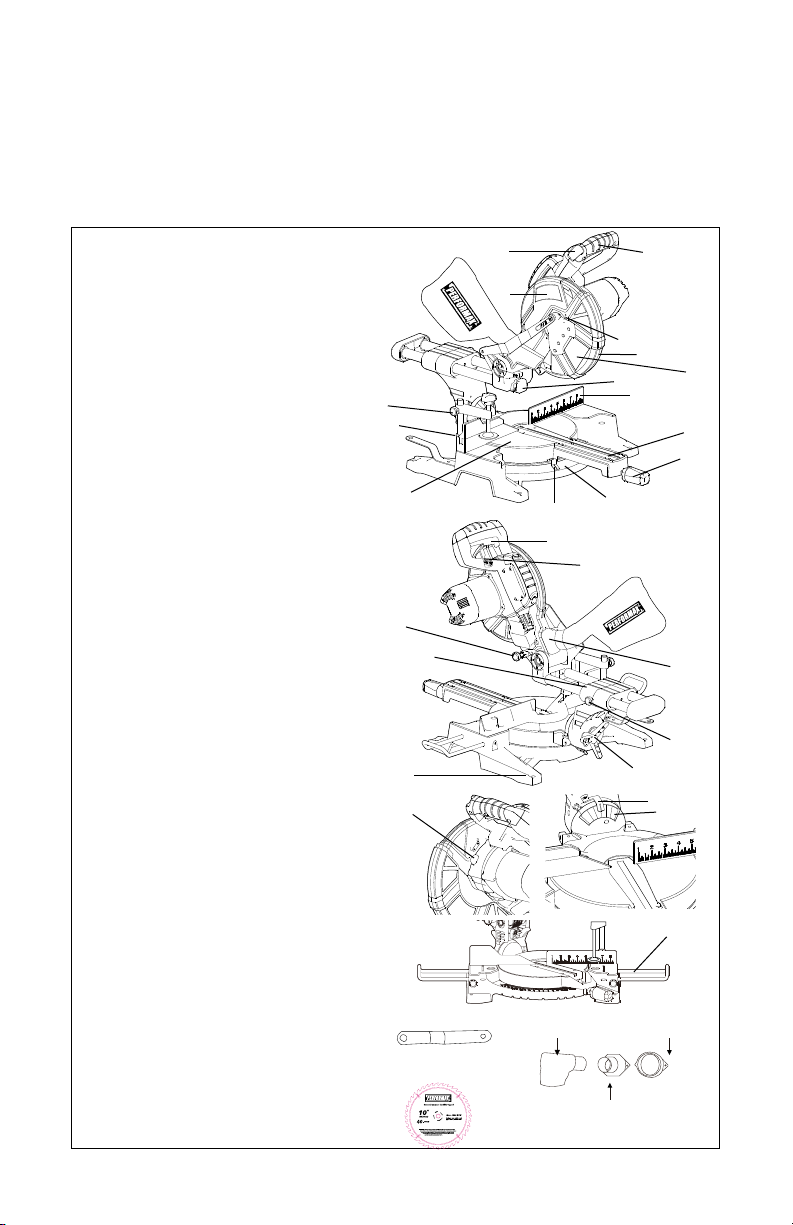
KNOW THE COMPOUND MITER SAW (See Fig. 1)
Before attempting to use this Compound Miter Saw, become familiar with all of
its operating features and safety requirements.
Fig. 1
1. ON/OFF trigger switch
2. Horizontal, rubberized D-handle
3. Safety lock-off button
4. Upper blade guard
5. Blade-screw guard
6. Dust-extraction port
7. Saw blade
8. Laser guide
9. Mounting holes
10. Miter table
11. Miter-angle scale
12. Throat plate
13. Miter-angle indicator
14. Miter lock
15. Clamp mounting holes
16. Fence
17. Lower blade guard
18. Spindle-lock button
19. Laser ON/OFF switch
20. Stop latch
21. Bevel-angle scale
22. Bevel lock
23. Bevel-angle indicator
24. Extension wings
25. Hold-down clamp
26. Slide lock
27. Slide rail assembly
25
15
20
10
9
18
10
27
3
4
13
1
19
11
2
5
7
8
17
16
12
14
6
26
22
23
21
24
Page 11
ASSEMBLY
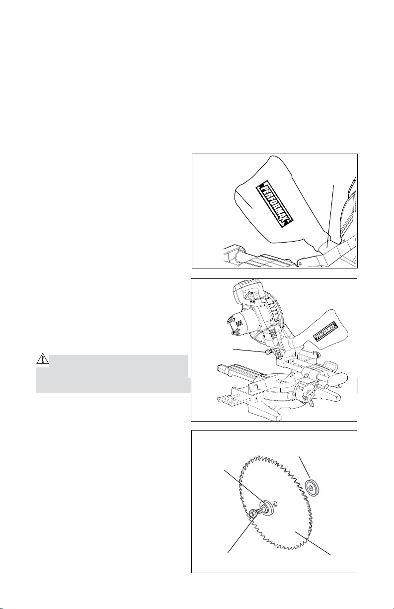
INSTALLING THE DUST BAG (see Fig. 2)
Make sure the dust-collector bag is upright (reference the performax logo on
the bag), and slide the collar of the dust-collector bag over the dust-extraction
port until it is attached securely.
Installing the adaptor for a shop vacuum
Remove the dust-extraction port by removing the two screws that hold it in
place. Attach the shop vacuum
adaptor using the same two screws.
Releasing and locking the saw head
Fig. 2
Dust bag
Dust-extraction port
1. Press the saw head down and hold
it lightly. Pull out the stop latch
in order to release the saw head.
The saw head should move up and
down freely (see Fig. 3).
2. Place the saw head at the lowest
position. Insert the stop latch in
order to lock the saw head for
Fig. 3
transporting and storage.
REMOVING THE BLADE (see Fig.
4)
WARNING: To reduce the risk of
injury, always unplug the tool before
removing or installing a blade.
stop latch
1. Unplug the tool.
2. Raise the saw head.
3. Remove the upper screw on the
blade-screw guard (Fig. 1, #5) by
turning it counter-clockwise using
a screwdriver(not included).
4. Lift and hold up the lower blade
guard, and rotate the blade-screw
guard in order to expose the
threaded blade screw.
5. Press and hold the spindle-lock
button (Fig. 1, #18), and rotate the
Fig. 4
Outer flange
Threaded blade screw
11
Inner flange
Blade
Page 12
blade at the same time until it locks into position.
6. Use the wrench (included) to turn the threaded blade screw clockwise, and
remove the threaded blade screw.
7. Remove the outer flange and the blade. Wipe the flanges and spindle in order
to remove any dust and debris.
Installing the blade
IMPORTANT: Do not use thin-kerf blades. Thin-kerf blades can deflect and
contact the guard, which can cause injury to the operator.
1. Unplug the saw.
2. Ensure that the inner flange is properly installed.
3. Match the arrow on the blade with the arrow on the upper blade guard. Make
sure the teeth of the blade are pointing downward. Install the selected blade
by sliding the blade into the upper blade guard and then placing the blade
into position.
4. Install the outer flange.
IMPORTANT: Make sure the flat side of the flange is placed against the blade.
5. Press and hold the spindle-lock button, and use the wrench (included) to turn
the blade screw counter-clockwise until the lock engages. Securely tighten
the blade screw.
6. Rotate the blade-screw guard into position, and use the screwdriver to
securely tighten the screw by turning it clockwise. Remove the wrench, and
store it in a safe place.
7. Make sure the spindle-lock button is released so that the blade will rotate
freely.
8. Lower the saw head, and check the clearance between the blade and the
miter table. The blade should rotate freely.
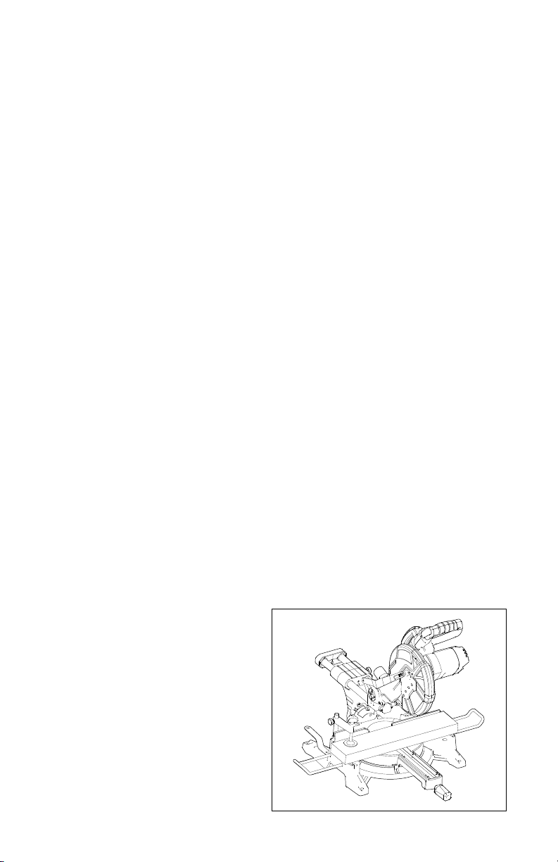
Installing extension wings
The extension wings support long
workpiece during cutting. (Fig. 5)
1. Insert both rails of an extension
wing through the holes on the
outside of the Miter Saw base.
2. Tighten the wing screw that locks
the extension wing in position.
Make sure the extension wings do
not move.
Fig. 5
12
Page 13
ADJUSTMENTS
WARNING: In order to avoid possible injury, disconnect the tool’s plug from
the power source before performing any assembly, adjustment, or repair.
IMPORTANT: Do not use thin-kerf blades. Thin-kerf blades can deflect and
contact the guard, which can cause injury to the operator.
Adjusting the miter
1. Lock the saw head in the down position, and loosen the miter-lock knob.
2. Hold the cutting handle firmly in order to rotate the miter table to the desired
angle. The most common angle settings (0°, 15°, 22.5°, 31.6° and 45°) have
positive stops.
3. Tighten the miter-lock knob, and release the saw head.
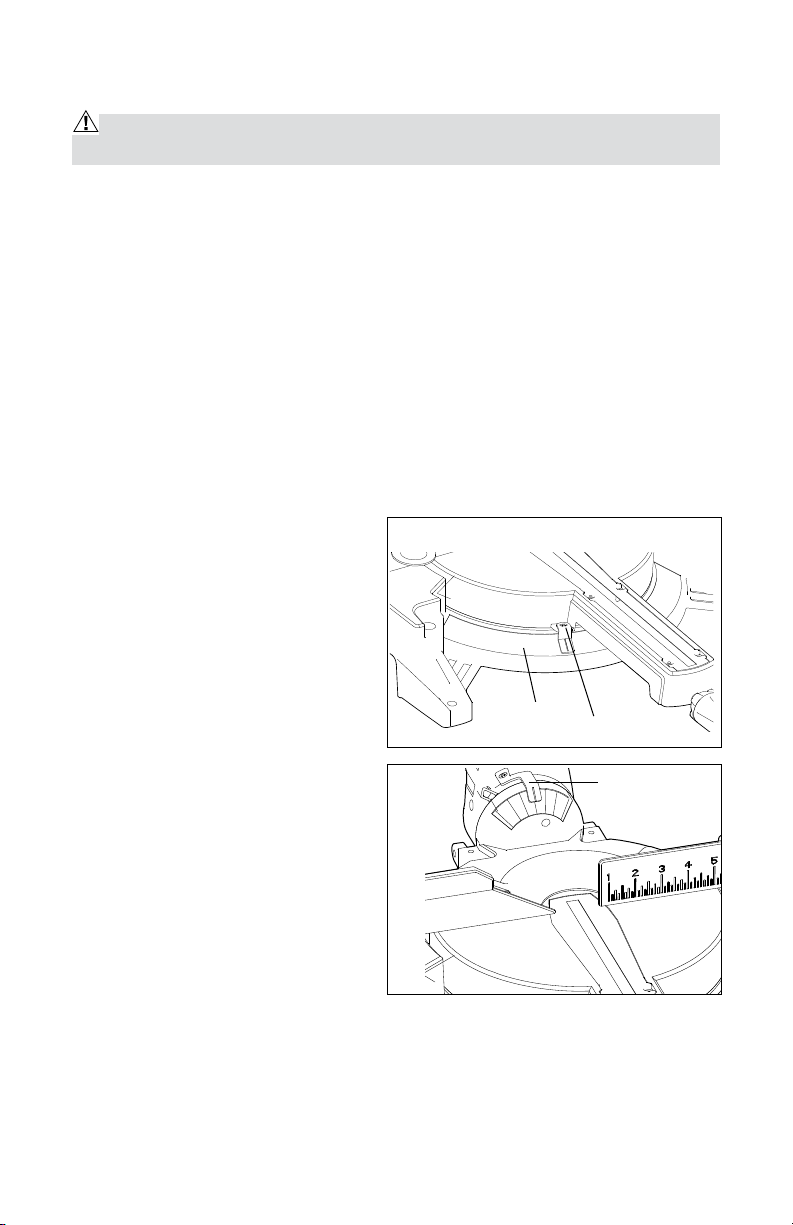
Adjusting the miter-angle indicator (if necessary)
1. Place the miter table at the zero position, making sure the miter lock is
secured in position.
2. Loosen the miter-angle indicator
screw, and adjust the indicator to
the “0” mark on the miter scale
(see Fig. 6).
3. Tighten the miter-angle indicator
screw.
Adjusting the bevel
1. When a bevel cut is required,
loosen the bevel lock (Fig. 1, #22)
by turning it counter-clockwise.
2. Tilt the saw head to the desired
angle, as indicated on the bevel
scale. The blade can be positioned
at any angle from a 90° straight cut
(0° on the scale) to a 45° left bevel
(see Fig. 7).
3. Tighten the bevel lock in order to
secure the saw head in position.
Fig. 6
Fig. 7
Miter scale
Indicator screw
bevel angle
indicator
13
Page 14

OPERATION
WARNING: In order to reduce the risk of injury, wear safety goggles or glasses with side shields.
WARNING: Before each use, check that the blade is free of cracks, loose
teeth, missing teeth, or any other damage. Do not use if damage is observed or
suspected.
WARNING: Always wait for the blade to stop completely, and unplug the tool
before changing accessories or making adjustment.
Moving the Miter Saw
WARNING: Before lifting or moving the Miter Saw, the Miter Saw must be OFF
and disconnected from the power supply.
Lift the Miter Saw only when the saw is OFF, the plug is removed from the
power-supply outlet, and the saw head is locked in the “down” position.
To avoid damage, never carry the Miter Saw by the cutting handle. Always
carry the saw by the base.
Mounting the Miter Saw
To prevent the tool from sliding, falling, or tipping during operation, the Miter
Saw can be mounted to a supporting surface, such as a level, sturdy worktable
or bench. Position the Miter Saw and the workbench in such a way as to allow
adequate room for crosscutting long workpiece.
Turn the Miter Saw OFF and disconnect it from the power supply.
To mount the Miter Saw, insert fasteners through the four holes in the base of
the Miter Saw, and use the fasteners to secure the saw to the table or bench.
Selecting the Desired Angle
Follow the steps described in “Adjusting the miter” and “Adjusting the bevel”
WARNING: The throat plate (see Fig. 1, #12) is factory-cut only for a 0º bevel
cut; the first cut made with the tool in the 45° bevel position will create a slot on
the throat plate.
WARNING: Always make sure the spindle-lock button is released so that the
blade will rotate freely.
WARNING: Make sure the stop latch is loose, and that the saw head moves
up and down freely. Ensure that all clamps and locks are tight and in place, and
that there is no excessive movement of Miter-Saw parts.
Selecting a workpiece
14
Page 15
Be cautious with pitchy, knotty, wet, or warped workpieces. These materials are
likely to create pinching conditions. Workpiece that bow and pinch may result in
the saw blade kicking back.
Before cutting, inspect for and remove any nails from the workpiece.
This tool is not recommended for cutting ferrous metals, such as iron and steel.
Only cut non-ferrous metals under the supervision of an experienced person.
Supporting the workpiece
WARNING: Never use the help of another person as a substitute for a table
extension or as support for a workpiece that is longer or wider than the basic
miter table. Never have another person help feed, support, or pull the workpiece
instead of using table extensions.
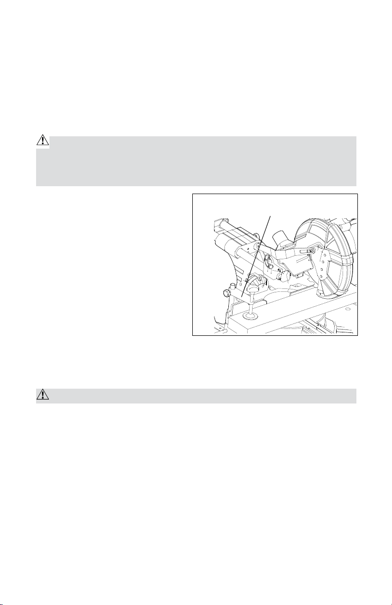
• Use the fence.
Fig. 8
workpiece clamp (included)
Align the workpiece flush against the
fence. This will help to eliminate the
tendency of the teeth of the blade to
bind. The fence can be used to support
miter, bevel, and compound cuts.
• Use the workpiece clamp
(included).
The workpiece clamp fits into the
clamp mounting holes on the back
of the fence. Securely clamp the
workpiece to the miter table. (See Fig. 8.)
Aligning the blade
WARNING: Do not look into the laser line.
• Do not aim the laser line at people or animals.
• Do not use the laser line on highly reflective materials. Doing so creates a
danger from reflected laser light.
• Have the laser repaired only by a qualified service technician.
• Do not insert hard objects into the laser lens.
• Clean the laser lens using a soft, dry brush.
Before starting a cut, draw the desired cutting line on the workpiece.
1. Press the laser ON/OFF switch (Fig. 1, #19) forward to start.
2. Align the left side of laser line with the right side of cutting line. The blade
will cut the line marked out on the workpiece.
15
Page 16
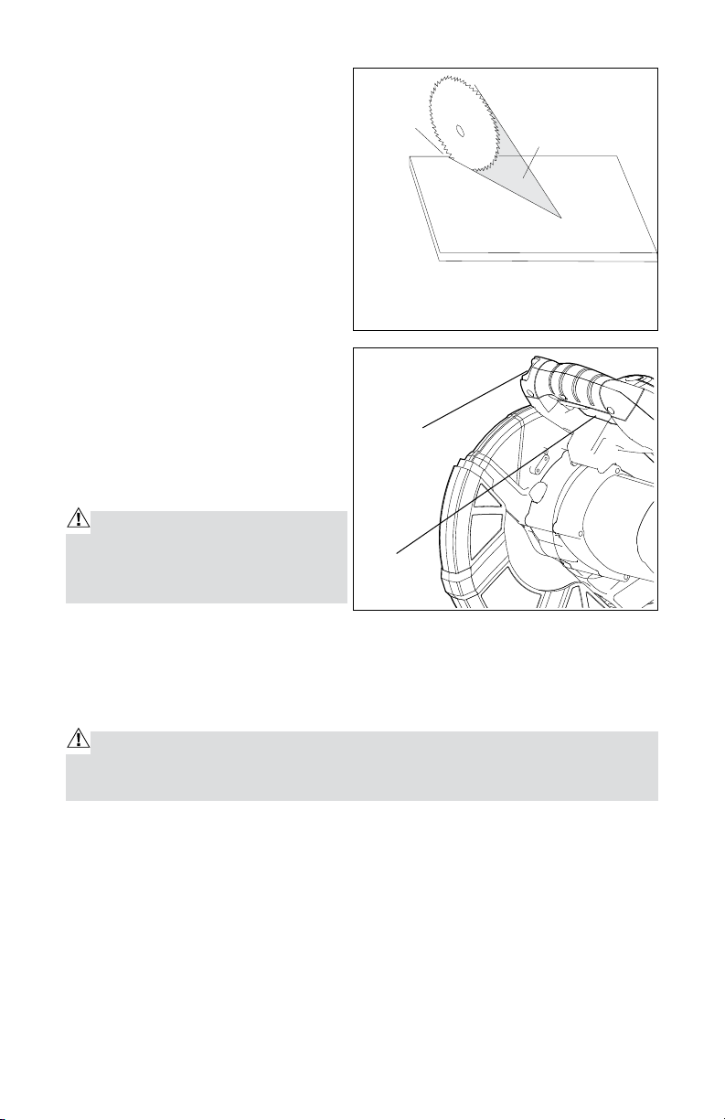
NOTE: The laser adjustment has
already been made at the factory.
Align the left side of the laser line
with the right side of the blade. Align
the user-marked line with the left side
of the laser line. (See Fig. 9)
Pay attention to body and hand
positions.
Proper positioning of the body and
hands when operating the Miter Saw
will make cutting easier and safer.
Never place hands near the cutting
area.
Hold the workpiece firmly against the
fence. Keep hands in position until the
ON/OFF trigger switch has been released
and the blade has completely stopped.
Starting the Compound Miter Saw
WARNING: Always hold the cutting
handle firmly. The starting and stopping action of the motor may cause the
handle to move up or down slightly.
Fig. 9
Cut area
includes
usermarked
line
The user-marked line aligns with the left side
of the laser line. the left side of the laser line
aligns the right side of the blade
Fig. 10
Safety
lock-off
button
Trigger
Laser line area
Timber
1. Plug the Compound Miter Saw into a power-supply outlet.
2. Push the safety lock-off button while squeezing the ON/OFF trigger switch to
turn the tool ON. (See Fig. 10.)
3. Wait until the blade reaches full speed.
WARNING: Always keep hands and fingers away from the cutting area. Any
part of the body coming into contact with a moving blade will result in serious
injury.
Stopping the Miter Saw and removing the workpiece
1. After completing a cut, release the ON/OFF trigger switch and push the laser
ON/OFF switch backward in order to turn it off.
2. Allow the saw blade to come to a complete stop. Do not remove the
workpiece from the sawing plate until the blade has stopped rotating.
3. Gently raise the saw head, and remove the workpiece. Ensure that the lower
blade guard can close easily.
4. Unplug the tool.
5. Remove loose or scrap pieces.
16
Page 17
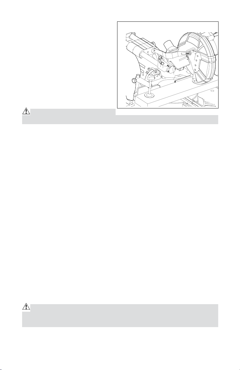
CROSSCUTTING (Fig. 11)
A crosscut is a cut made across the
grain of the workpiece. A straight
crosscut is a cut made with the miter
table set at the 0° position (Fig 11).
Miter crosscuts are made with the
miter table set at an angle other than
0°, either left or right.
Crosscutting with the Miter Saw
1. Unplug the saw.
WARNING: Failure to unplug the
saw could result in accidental start-up, which may cause serious injury.
2. Push in the locking pin in order to lock the saw arm in the down position.
3. Loosen the miter lock.
4. Firmly hold the base of the saw arm, and use it to rotate the miter table
while holding the saw base steady.
5. Quickly locate 0°, 15°, 22.5°, 31.6° and 45°, left or right, by the stops or
clicks at these angle settings.
6. Once the miter angle is set, tighten the miter-lock lever by tightening the
miter-lock knob.
7. Pull out the locking pin in order to release the saw arm.
8. Place the workpiece flat on the miter table, with one edge securely against
the fence. If the board is warped, place the convex side against the fence. If
the concave edge of the board is against the fence, the board could collapse
on the blade at the end of the cut, and jam the blade (Fig. 14 and 15).
9. Align the “red laser line” so that it is touching the right edge of the pencil line
on the workpiece.
10. Use the hold-down clamp to secure the workpiece against the saw table
and fence.
11. When cutting long workpiece, support the opposite end of the workpiece
with a roller stand or with another work surface that is level with the saw
table.
WARNING: In order to avoid serious personal injury, always tighten the miter-
lock lever securely before making a cut. Failure to do so could result in movement
of the control arm or miter table while making a cut.
Fig. 11
17
Page 18
CAUTION: Never use another person as an additional support for a workpiece
that is longer or wider than the basic saw table, or to help feed, support, or pull
the workpiece.
WARNING: In order to avoid serious personal injury, always keep hands outside of the “No-Hands Zone”, as marked on the saw table, or at least 3” (7.6 cm)
away from the blade. Also, never perform any cutting operation “freehand” (i.e.:
without holding the workpiece against the fence), because the blade could grab
the workpiece, causing it to slip and twist.
12. Before turning on the saw, perform a test of the cutting operation by lowering
the saw arm to make sure no problems will occur when the cut is made.
13. Hold the saw handle, and use the index finger to push the laser switch
forward to turn the laser light on.
14. To turn the saw on, push the safety lock-off button in with the thumb while
squeezing the On/Off trigger switch located under the handle (Fig. 1, #1 and
#3). Allow several seconds for the blade to reach maximum speed.
15. Slowly lower the blade into and through the workpiece.
16. Release the safety lock and the trigger switch, and turn the laser switch
off. Allow the saw blade to stop rotating before raising the blade out of the
workpiece.
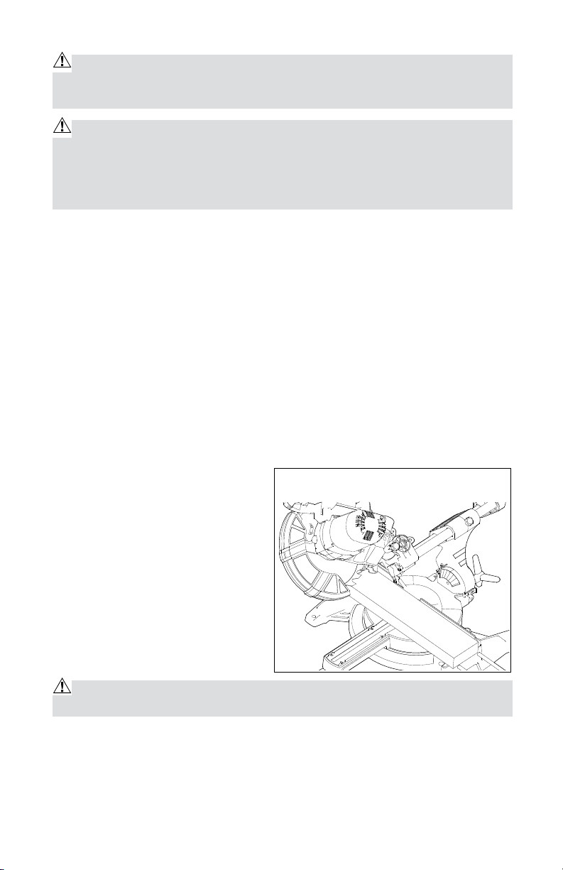
BEVEL CUTTING (Fig. 12)
A bevel cut is a cut made across the
grain of the workpiece with the blade
at an angle to the workpiece.
A straight bevel cut is made with
the miter table set at the 0° position
and the saw arm set at a bevel angle
between 0° and 45°.
Bevel Cutting with the Miter Saw
1. Unplug the saw.
WARNING: Failure to unplug the saw could result in accidental start-up,
which may cause serious injury.
2. Make sure the miter table is positioned at 0°and locked, and check that the
miter-table lock is locked and secured in position.
Fig. 12
18
Page 19

WARNING: In order to avoid serious personal injury, always tighten the miterlock lever securely before making a cut. Failure to do so could result in movement
of the control arm or miter table while making a cut.
3. Pull out the locking pin in order to release the saw arm.
4. To make a bevel cut, loosen the bevel-lock knob (Fig. 1, #22) by turning the
knob counter-clockwise.
5. Tilt the saw arm to the desired bevel angle, as indicated on the bevel scale.
The blade can be positioned at any angle, from a 90° straight cut (0 on the
scale) to a 45°left bevel (Fig. 12).
WARNING: Tighten the bevel-lock knob in order to secure the saw arm in
position.
6. Place the workpiece flat on the miter table, with one edge securely against
the fence. If the board is warped, place the convex side against the fence. If the
concave edge of the board is against the fence, the board could collapse on the
blade at the end of the cut, and jam the blade (Fig. 14 and 15).
7. Align the red laser line so that it is touching the right edge of the pencil line
on the workpiece.
8. Use the hold-down clamp to secure the workpiece against the Miter Saw
table and fence.
9. When cutting long workpiece, support the opposite end of the workpiece with a
roller stand or with another work surface that is level with the saw table.
CAUTION: Never use another person as an additional support for a workpiece
that is longer or wider than the basic saw table, or to help feed, support, or pull
the workpiece.
WARNING: In order to avoid serious personal injury, always keep hands outside the “No-Hands Zone”, as marked on the saw table, or at least 3” (7.6 cm)
away from the blade. Also, never perform any cutting operation “freehand” (i.e.:
without holding the workpiece against the fence), because the blade could grab
the workpiece, causing it to slip and twist.
10. Before turning the saw on, perform a trial of the cutting operation by lowering
the saw arm to make sure no problems will occur when the cut is made.
11. Hold the saw handle, and use the index finger to turn the laser switch on by
pushing it forward.
12. To turn the saw on, push the safety lock-off button in with the thumb while
squeezing the On/Off trigger switch located under the handle (Fig. 1, #1 and
#3). Allow several seconds for the blade to reach maximum speed.
13. Slowly lower the blade into and through the workpiece.
19
Page 20
14. Release the safety lock and the trigger switch, and turn the laser switch
off. Allow the saw blade to stop rotating before raising the blade out of the
workpiece.
CAUTION: Always perform a “dry run” cut in order to determine whether the
operation being attempted is possible before power is applied to the Miter Saw.
Slide Cutting
This type of cut is used mainly for wide pieces. A positive blade hook of
10 degrees or more is recommended for best performance when making
aggressive cuts or cutting thicker materials.
WARNING: Never pull the saw toward you during a cut. The blade can suddenly climb up on top of the workpiece and force itself toward you.
Follow these instructions for making your slide cut:
1. Properly position the workpiece. Make sure the workpiece is clamped firmly
against the table and the fence.
WARNING: Use a clamping position that does not interfere with the cutting
operation. Before switching the Miter Saw ON, lower the head assembly to make
sure the clamp clears the guard and the head assembly.
2. Loosen the slide rail locking knob.
3. Grasp the switch handle, and pull the head assembly away from the fence
until the blade clears the workpiece, or to its maximum extension if the blade
cannot clear the workpiece.
4. Activate the switch. Always allow the blade to reach full speed before cutting.
5. Lower the head assembly all the way down, and cut through the edge of the
workpiece.
6. Push (but do not force) the head assembly toward the fence all the way to
the rear position in order to complete the cut.
7. Wait until the blade comes to a
complete stop before returning the
head assembly to the raised position
and/ or removing the workpiece.
Fig. 13
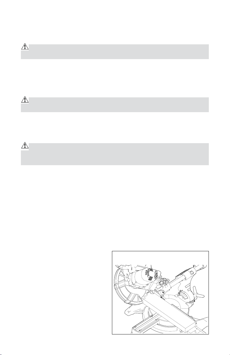
COMPOUND MITER CUTTING (Fig.
13)
A compound miter cut is a cut made
using a miter angle and a bevel angle
at the same time. This type of cut is
used for decorative moldings, picture
frames, and other fine joinery.
20
Page 21

To make this type of cut, the miter table must be rotated to the correct miter
angle and the saw arm must be tilted to the correct bevel angle.
Always take special care when making compound miter cuts, due to the interaction
of the two angle settings.
Adjustments of miter and bevel settings are interdependent. Whenever the miter
setting is adjusted, the effect of the bevel setting also changes. Whenever the
bevel setting is adjusted, the effect of the miter setting is changed.
It may take several settings to obtain the desired cut. The first angle setting
should be checked after setting the second angle, because adjusting the second
angle affects the first.
Once the two correct settings for a particular cut have been obtained, always
make a test cut in scrap material before making a finish cut in good material.
Making a Compound Miter Cut with the Miter Saw
1. Unplug the saw.
WARNING: Failure to unplug the saw could result in accidental start-up,
which may cause serious injury.
2. Pull out the locking pin in order to release the saw arm.
3. Loosen the miter-lock knob in order to loosen the miter table.
4. Hold the base of the saw arm firmly, and use it to rotate the miter table while
holding the saw base steady.
5. The 0°, 15°, 22.5°, 31.6°, and 45°left and right settings are quickly
identifiable with the stops at the angle settings.
6. When the desired miter-table setting is achieved, tighten the miter-lock.
WARNING: In order to avoid serious personal injury, always tighten the miterlock lever securely before making a cut. Failure to do so could result in movement
of the control arm or miter table while making a cut.
7. To set the bevel angle, loosen the bevel-lock knob (Fig. 1, #22) by turning the
knob counter-clockwise.
8. Tilt the saw arm to the desired bevel angle, as shown on the bevel scale.
Bevel angles can be set from 0°to 45°left.
9. Once the saw arm has been set at the desired angle, tighten the bevel-lock
knob securely.
10. Place the workpiece flat on the miter table, with one edge securely against
the fence. If the board is warped, place the convex side against the fence. If
the concave edge of the board is against the fence, the board could collapse
on the blade at the end of the cut and jam the blade (Figs. 14 and 15).
11. Align the red laser line so that it is touching the right edge of the pencil line
21
Page 22
on the workpiece.
WrongWrong
Right
Top View
WrongWrong
12. Use the hold-down clamp to secure the workpiece against the saw table
and fence.
13. When cutting long workpiece, support the opposite end of the workpiece with a
roller stand or with another work surface that is level with the saw table.
CAUTION: NEVER use another person as an additional support for a workpiece that is longer or wider than the basic saw table, or to help feed, support, or
pull the workpiece.
WARNING: To avoid serious personal injury, always keep hands outside the
“No-Hands Zone”, as marked on the saw table, or at least 3” (7.6 cm) away
from the blade. Also, never perform any cutting operation “freehand” (i.e.: without holding the workpiece against the fence), because the blade could grab the
workpiece, causing it to slip and twist.
14. Make sure there will be no obstructions to interfere with making the cut.
15. Hold the saw handle, and use the index finger to turn the laser switch on by
pressing it.
16. To turn the saw on, push the safety lock-off button in with the thumb while
squeezing the On/Off trigger switch located under the handle (Fig. 1, #1 and
#3). Allow several seconds for the blade to reach maximum speed.
17. Slowly lower the blade into and through the workpiece.
18. Release the safety lock and trigger switch, and turn the laser switch off. Allow
the saw blade to stop rotating before raising the blade out of the workpiece.
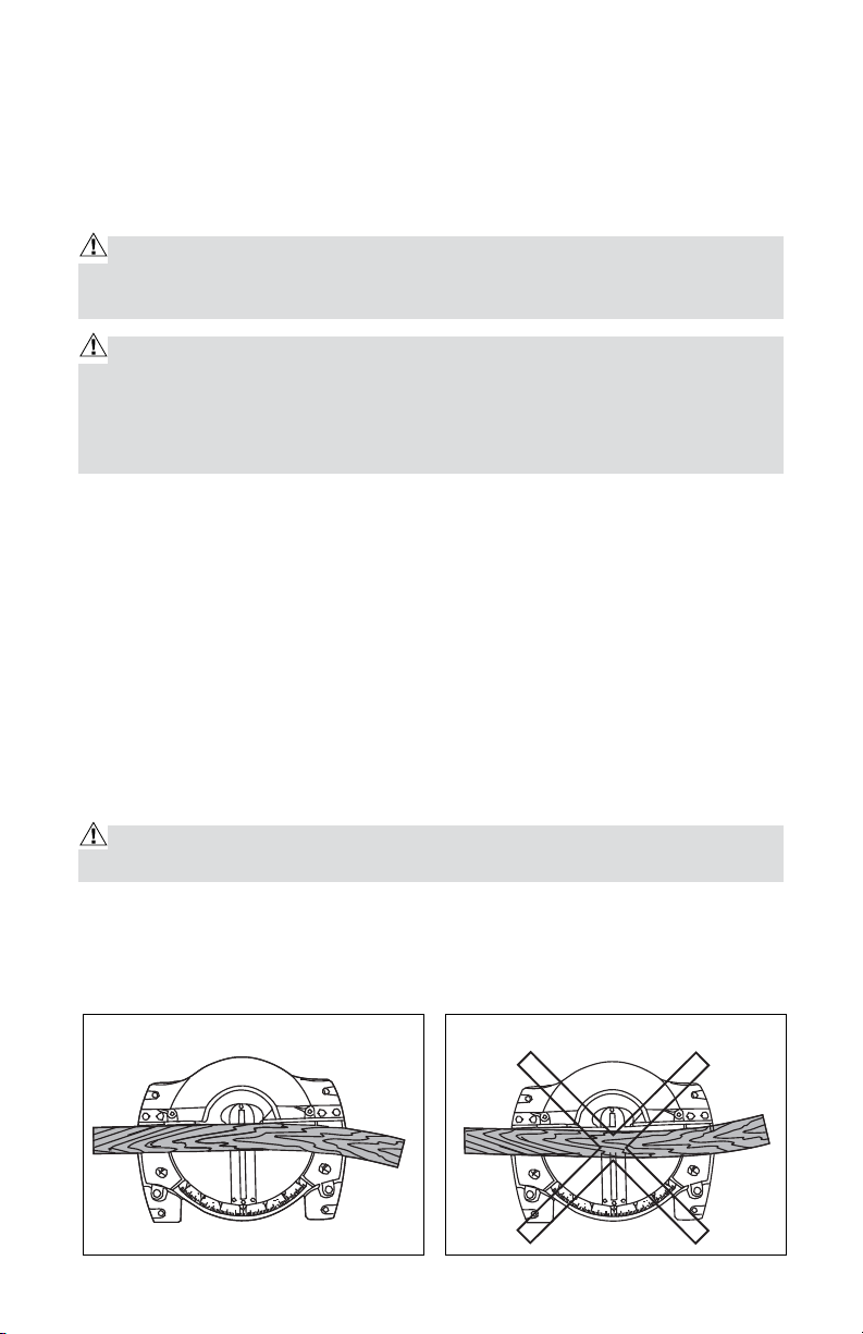
CUTTING WARPED MATERIAL (Fig. 14 and 15)
WARNING: In order to avoid kickback and serious personal injury, never pos-
ition the concave side of bowed or warped material against the fence.
When cutting warped material, be certain that the material to be cut is positioned
on the miter table with the convex side against the fence, as shown (Fig. 14).
If the warped material is positioned the wrong way (Fig. 15), it will pinch the
blade near the end of the cut.
Fig. 14 Fig. 15
22
Page 23

MAINTENANCE
Before cleaning or performing any maintenance, make sure the Miter Saw has
been disconnected from the power supply. Keep all ventilation openings clean.
Avoid using solvents when cleaning plastic parts. Most plastics are susceptible
to damage from various types of commercial solvents, and may be damaged by
their use. Use a clean cloth to remove dirt, oil and grease.
WARNING: Do not allow improper materials, such as brake fluid, gasoline,
petroleum-based products, penetrating oil, etc., to come into contact with plastic
parts. These substances contain chemicals that can damage, weaken or destroy
plastic.
WARNING: In order to ensure safety and reliability, all repairs should be performed by a qualified service technician
TROUBLESHOOTING
PROBLEM PROBABLE CAUSE
Electric hand brake has
failed
Brake does
not stop
blade within
6 seconds.
Motor does
not start.
Angle of cut
is inaccurate.
Motor brake overheated
from use of defective or
wrong sized blade or rapid
ON/OFF cycling
Blade screw is loose Retighten the blade screw.
Saw not plugged in
Fuse or circuit breaker
Miter table unlocked
Too much sawdust under
table
SUGGESTED CORRECTIVE
ACTION
Have the saw repaired by a
qualified service technician.
Use a recommended blade.
Check that all cords are
plugged in.
Check the time-delayed fuse
or circuit breaker.
Use miter table locking
lever. See section entitled
ADJUSTMENTS”
Vacuum or blow out dust.
Wear Eye Protection!
23
Page 24

Cutting arm
cannot fully
raise, or
blade guard
cannot
fully close.
Parts failure
Pivot spring not replaced
properly after service
Sawdust build up
Saw-head locking pin not
set properly
Call the Toll-free Helpline:
1-866-858-2664.
Call the Toll-free Helpline:
1-866-858-2664.
Clean and lubricate moving
parts.
Check, adjust, and properly
set the saw-head locking pin.
Blade binds,
jams, or
burns
Wood.
Saw vibrates
or shakes.
Laser line
projection is
hard to see.
ACCESSORIES
Improper operation
Dull blade Replace or sharpen blade.
Improper blade Replace blade.
Warped blade Replace blade.
Saw blade damaged Replace blade.
Saw blade loose Tighten blade screw.
Saw not properly fastened
down
Workpiece not properly
supported
Light in work area is too
bright
Sawdust on the laser lens
See section entitled
OPERATION.
Fasten saw to stand, bench,
or table.
Properly support or clamp
workpiece.
Move the Miter Saw to a work
area with proper light.
Clean laser lens using a soft,
dry brush.
• 1 Pc - 40T carbide-tipped blades
• 1 pc - hold down clamp
• 1 pc - dust collection bag
• 1 pair - extension rails
• 1 pc - wrench
• 1 pc - vacuum adaptor
24
Page 25

PERFORMAX® Sliding Compound Miter Saw WARRANTY
30-DAY MONEY BACK GUARANTEE:
This PERFORMAX
Guarantee. If you are not completely satisfied with your PERFORMAX® brand
power tool for any reason within thirty (30) days from the date of purchase,
return the tool with your original receipt to any MENARDS
we will provide you a refund – no questions asked.
®
brand power tool carries our 30-Day Money Back
®
retail store, and
2-YEAR LIMITED WARRANTY:
®
This PERFORMAX
brand power tool carries a 2-Year Limited Warranty
to the original purchaser. If, during normal use, this PERFORMAX® power
tool breaks or fails due to a defect in material or workmanship within two
(2) years from the date of original purchase, simply bring this tool with the
original sales receipt back to your nearest MENARDS® retail store. At its
discretion, PERFORMAX® agrees to have the tool or any defective part(s)
repaired or replaced with the same or similar PERFORMAX® product or
part free of charge, within the stated warranty period, when returned by the
original purchaser with original sales receipt. Not withstanding the foregoing,
this limited warranty does not cover any damage that has resulted from
abuse or misuse of the Merchandise. This warranty: (1) excludes expendable
parts including but not limited to blades, brushes, belts, bits, light bulbs, and/
or batteries; (2) shall be void if this tool is used for commercial and/or rental
purposes; and (3) does not cover any losses, injuries to persons/property or
costs. This warranty does give you specific legal rights and you may have
other rights, which vary from state to state. Be careful, tools are dangerous if
improperly used or maintained. Seller’s employees are not qualified to advise
you on the use of this Merchandise. Any oral representation(s) made will not
be binding on seller or its employees. The rights under this limited warranty
are to the original purchaser of the Merchandise and may not be transferred
to any subsequent owner. This limited warranty is in lieu of all warranties,
expressed or implied including warranties or merchantability and fitness for
a particular purpose. Seller shall not be liable for any special, incidental, or
consequential damages. The sole exclusive remedy against the seller will be
for the replacement of any defects as provided herein, as long as the seller
is willing or able to replace this product or is willing to refund the purchase
price as provided above. For insurance purposes, seller is not allowed to
demonstrate any of these power tools for you.
For questions / comments, technical assistance or repair parts –
Please Call Toll Free at: 1-866-858-2664 (M-F 8am – 6pm)
SAVE YOUR RECEIPTS. THIS WARRANTY IS VOID WITHOUT THEM.
25
Page 26

262728
Page 27

Page 28

 Loading...