

Page 1

Gemini 105Mc
Owner’s Manual
Boat Name:
Hull Number:
Owner:
Address:
Sail Number:
Engine Number:
Registration Number:
Documentation Number:
Manual Version: 2.5
Publication Date: 3/4/2005
7364 Edgewood Road Annapolis Maryland 21403
Phone 410.626.2720
www.performancecruising.com
Owner InfoCenter: www.performancecruising.com
Page 2
Gemini 105Mc Owner’s Manual
ongratulations on the purchase of your new Gemini 105Mc cruising catamaran and
welcome to the Gemini family. There are over 800 Gemini catamarans crui sing all over
the world, and we’re pleased to include you as a member of this select group of
C
your appreciation of the Gemini’s qualities, we encourage you to thoroughly read through the
entire manual before getting underway on your new boat.
This manual covers the proper operation and maintenance of all the aspects and syste ms aboard
the Gemini 105Mc. If a particular topic isn’t covered in enough detail, let us know via e-mail. We
regularly update the manual and make new versions available through the Performance Cruising
Owner InfoCenter website (http://www.mypci.net). The InfoCenter website also hosts an owners’
technical forum that addresses specific questions with correct and safe answers as well as advice
from the factory or even other Gemini owners.
discriminating sailors who appreciate performance, value, form, and function. To better
Whether this is your first boat or your first multihull, we encourage you to obtain handling and
operating experience before assuming command of the boat. Your dealer or the factory can
recommend local sailing schools and/or competent instructors.
Be sure to keep this manual onboard for quick reference. You can always download and print an
extra copy from the website. The manual will help you get better, more trouble-free performance
and long life from your boating investment.
We wish you and your crew many years of enjoyable, safe sailing on your Gemini.
Performance Cruising Inc.
Note: Third-party items on the boat are individually warranted. Where such items are discussed in the manual, a
symbol appears to indicate that further contact information is available on the contact page at the end of the
manual.
2 Copyright © 2004 Performance Cruising Inc.
Page 3

Gemini 105Mc Owner’s Manual
Table of Contents
Topic Page
Quick Start 4
Engine 4
Electric Panel 4
Shore Power 4
Water 5
Propane 5
Stove 5
Refrigerator 5
Hot Water Heater 6
Toilet 6
Centerboards 6
Rudders 7
Batteries and Switch 4
Sails 8
Plumbing, Head, and Fresh Water 8
Water Fill 8
Water Tank Selection 8
Pressure Pump 8
Galley Tip Toe Pump 8
Shower/Sump 8
Toilet 8
Hoses / Clamps 9
Cockpit Shower 9
Holding Tank 9
Mains Adapter 9
Water Maker 9
Saltwater Pump 9
System Overview 11
Propane 12
Xintec Control Panel 12
Tanks 12
Junction and Solenoid 12
Copper and Fittings 13
Checking for Leaks 13
Stove 13
Refrigerator 13
Refrigerator on 110v 14
Safety 12
Shore Power 15
Air Conditioning 16
12 Volt Power 17
Battery Switch 17
25 Amp Fuse 18
Wiring Code 19
Switch Panel 19
VHF 19
AM/FM Stereo 19
Cabin Lights 19
Bulbs 19
Mast Wires 20
Mast Wiring Diagram 21
Batteries 17
Topic
Engine 24
Gear Lever / Throttle 24
Fuel Tanks/Gauges 24
Hot Water / Cabin Heater 24
Sonic Drive Leg 24
Centerboards and Rudders 26
Maintenance 26
Illustrations 27
Performance and Use 28
Motoring / Winds / Offshore 28
Rudders 28
Construction 30
Stress & Movement 30
Constructions Differences 31
Design Considerations 32
Interior Molds 32
Buoyancy Tanks 32
Leaks 32
Sails and Sailing 33
Main Sail & Reefing 33
Headsail & Reefing 33
Spinnaker s 34
Heavy Weather 35
Offshore Cruising 36
Notes on Sailing a New Boat 37
Coast Guard Kit 38
Offshore Sailing Kit 38
Anchoring 39
Retrieving the Anchor 40
Docking & Mooring 41
Picking up a Mooring 41
Sea Anchors 42
Effects of Lightning 42
Maintenance 43
Cleaning and Care of Fiberglass 43
Bottom Paint 43
Blisters 43
Teak Cleaning 44
Window Care & Maintenance 44
Hauling and Trucking 45
Winterizing 46
Page
Cooling Water 24
Operation 26
Deck & Hull Construction 30
Sailing Rig Types 33
Setting the Anchor 39
Heaving Lines 41
Mast and Rigging 22
Rig Tensioning 22
Boom 23
Bridge Clearance 22
Operational Checklists 47
Contact Information 48
Addendums 53
Westerbeke 30B Quick Notes 58
Bottom Paint FAQ 60
3 Copyright © 2004 Performance Cruising Inc.
Page 4

Gemini 105Mc Owner’s Manual
Gemini Quick Start Guide
Batteries and Battery Switch
The Gemini comes with three (3) number 24 deep
cycle marine batteries. These are located under the
navigation table in the port hull with the main battery
switch just above them. There is room for an additional battery in the compartment.
To turn the batteries “On”, turn switch to position '1'
(which includes (2) two batteries). Everything on the
boat will go through battery
'1' including engine start.
Switch position '2' includes (1)
one battery. Never leave the
switch in the “Both” position
as there is no reserve battery. When switching from
position '1' to position '2',
move the switch through the
“Both” position, not “Off.”
Failure to do so while the engine is operating can result in damage to the alternator.
Westerbeke Diesel Engine
Before starting the engine, always make sure that the
cooling water will reach the engine by turning the
engine seacock lever to the allow water from the sea
to flow. The engine seacock is under starboard aft
bunk towards the front. The seacock has three positions:
1. In from the sea
2. Closed
3. Fresh Water Intake (for winterizing)
Placing the handle all the way up brings seawater in
to cool the engine if the hose is facing aft. (With the
hose facing forward, the handle needs to be down for
open) With the handle pointing straight out away
from the hull the seacock is closed and with the handle all the way down, a fresh-water hose can be
hooked up to the seacock to flush fresh water into the
engine for winterizing. (Handle up if hose faces forward).
There is also an inline water strainer. The strainer
reservoir should be full of water.
red hydraulic oil reservoir. The leg will begin to drop
and then lock into position with a loud click. Once in
position, re-tighten the black knob.
To start the engine, make sure gear lever is in neutral. With the lever vertical, use both hands, and with
the left hand pull the throttle lever 1/4" outward
while the right hand pushes the lever forward to an
angle of 45º. With the throttle in the “out” position,
the gears are not engaged.
Next, turn the ignition key to run and the buzzer will
sound. First, press the preheat button for approximately 15 seconds then, while still pressing preheat,
press the start button to turn the engine over. Following starting, you should always check that cooling
water is coming out of the exhaust on the transom
beside the drive leg. If no cooling water is coming
from the exhaust, the engine seacock is in the incorrect position or clogged in which case you should turn
off the engine and correct the problem.
To engage the gears and propeller, move the gear
lever back and the lever will set into position. Push
the handle forward for forward movement and backward for reverse.
To stop the engine, first return the throttle to neutral. Next, lift the silver knob on the right above the
instrument panel, which stops fuel from getting to
the engine. Turning the key to the “off” position will
not turn the engine off. Following turning the engine
off, turn the key to the “off” position to stop the
buzzer. Turning the key to the “off” position with
the engine running can result in damage to the alternator. Remember to push the silver “kill” knob back
down, otherwise the engine will not re-start.
To raise the leg following motoring make sure the
black knob is tightened on the hydraulic oil reservoir.
Pull out the chrome knob in the back of the locker to
release the reverse lock, and then pump the red handle. The first pump will be hard and then it should be
possible to feel the leg slip out of reverse lock and
start to come up. At that point, let the chrome knob
go and continue pumping. Once the unit is up, turn
the red stopcock vertical to stop any fluid loss
through the pump so that the leg will stay up.
Regarding fuel; inside the center top hatch on the
stern are two (2) valves to select the fuel from either
the port or starboard 18-gallon tank. These two valves
must point the same way. One is fuel feed the other
is return. These valves simply point to starboard or
port. The short, pointy end of the handle indicates
which tank is in use.
To lower the sonic drive leg turn the red stopcock
lever in the starboard cockpit locker inline with the
hydraulic line and then loosen the black valve on the
Electric Panel
There are 2 - 12-volt electric panels with circuit
breakers for the following:
• Compass Light
• Masthead Lights
• Running Lights
• Anchor Light
• Instruments
• Fans
• Shower Pump
4 Copyright © 2004 Performance Cruising Inc.
Page 5

Gemini 105Mc Owner’s Manual
Gemini Quick Start Guide
• Cabin Lights
• VHF Radio
• Deck Lights
• Gas Valve (for Propane Monitor)
• Stereo / Television
• Spare
Both 12-volt outlets located next to the panel and
above the refrigerator run from the cabin lights circuit breaker.
There is a 25-amp fuse (with spare) located under the
battery switch protecting the switch panel. This fuse
handles all 12 volt appliances.
Shore Power
The Gemini shore power inlet is rated for 30 amps (24
amps continuously) and is run with 10 gauge wire.
The switches on the 110v panel are all circuit breakers.
The top two are linked together as the main breaker.
In the “ON” position, a green light indicates proper
operation while a red light indicates a bad connection
or possibly a badly wired marina.
Under the main breaker are circuit breakers for the
port outlets, starboard outlets, refrigerator, water
heater, and spare (usually used for air conditioning).
The 110v panel has a slide to prevent using the refrigerator, water heater, and air conditioner all at the
same time. Two of the three can be operated at the
same time, however, all three would require an excess of 24 amps.
pump is not on.
Important: Be sure to have the cold-water faucet
open in the galley when using the foot pump. Failure to do so can result in breakage.
Propane
In the starboard aft cockpit locker there are two, 20
lb. vertical propane tanks with overfill protection.
Only one tank can be connected to the propane system at a time. The propane comes from the tank via a
regulator and rubber hose to a junction box. From
the rubber hose the propane can either go through
the solenoid or through the by-pass.
From the back of the junction box are 2 copper hoses
going to each appliance.
The propane monitor is switched on at the 12 volt
switch panel. The solenoid opens and closes with an
audible “click.” The solenoid requires one (1) amp
per hour to remain in the open position. With such a
relatively high power requirement, there is a by-pass
valve intended for use while sailing. To use the bypass, move the connection lever so that it is inline
with the bypass copper pipe and turn off the solenoid
on the propane panel.
Caution: If the boat is unattended and connected to
shore power, it is highly advisable to turn the solenoid
on along with a battery charger to avoid depleting the
batteries.
Stove
The optional microwave operates on the starboard
outlet breaker.
Water
The Gemini has two translucent 30-gal tanks under
the port and starboard aft bunks. The tanks are filled
individually from the water intakes on either side of
the mainsheet track.
Only one tank is used at a time and is selected using a
'Y' valve to select water draw from either the port or
starboard tank. Turning the valve (which is mounted
on the wall in the port aft cabin) clockwise selects
the starboard tank. Turning it counter-clockwise selects the port tank.
There is an electric 12-volt pump for pressure water
to each sink, the shower, and the hot water heater.
There is a dedicated pressure water switch on the 12
volt panel.
There is a foot pump in the galley to manually pump
water from the selected tank if the pressure water
The Gemini comes standard with a two burner, broiler
and oven unit.
To operate burners on top of unit, as well as in broiler
and oven, push knobs in to override flame failure
safety cut off device. Turn to 'on' position, and apply
a flame. Hold knob in for a few seconds then set knob
to desired setting.
The oven has a thermostat. Turning the knob on the
front of the unit sets thermostat up to 480º.
Refrigerator
The refrigerator operates on 110v (shore power) or
propane. Before lighting the refrigerator on propane
or turning on with 110v, make sure the refrigerator
vent (located under the wheel in the cockpit) is removed and the 12V refrigerator fan is on. The switch
for the fan is inside the shelf unit at the side of the
refrigerator. Be sure to turn on the “Refrigerator”
switch on the 12v panel.
The refrigerator operates automatically when con-
5 Copyright © 2004 Performance Cruising Inc.
Page 6

Gemini 105Mc Owner’s Manual
Gemini Quick Start Guide
nected to either shore power or propane. The unit
will prefer electric power if connected. Otherwise,
the refrigerator will use propane and light itself automatically. To use the refrigerator on shore power,
turn the refrigerator breaker on the shore power
panel to “On”. Also, turn the Refrigerator breaker on
the 12 volt panel to “On”. The 12 volt breaker operates the cooling fan and lighter. To use the refrigerator on propane, turn the shore power refrigerator
breaker to “Off” and select “Propane” on the refrigerator control panel. You may hear the unit click
several times as it attempts to light itself. Be sure
that the propane bottle is open and that propane is
getting to the unit. If the refrigerator is not successful in lighting itself, the “Check” light indicator will
come on. In most cases, turning the unit “Off” and
then back on will reinitiate the automatic lighting
procedure and the unit will operate normally.
As the refrigerator operates completely silently, the
means by which to tell if it is operating correctly
(besides the interior getting cold) is to feel the chimney flashing on the back of the refrigerator. The
chimney is accessible through the refrigerator ventilation hatch in the cockpit.
Hot Water Heater
The hot water heater is a six-gallon tank stored in
front of the water tank under the bunk in the port aft
cabin.
When the engine is running, a heat exchanger coil
coming from the engine heats the water in the heater
tank. There is a red handled valve in the front end of
the engine compartment that is used to shut off the
hot water going to the water heater tank. When the
handle is pointing down, the engine is not heating the
water. When the handle is horizontal, the water in
the tank is being heated.
When on shore power, a switch on the main 110V
panel turns on a 110V electric element in the tank,
which heats the water.
Caution: Do not operate the hot water heater on 110v
without water in the heater tank—otherwise you will
likely burn out the heating element. To fill the heater
tank, turn on a hot water faucet until water comes
out, indicating the tank is full. Just as important is to
make sure you do not run out of water in your 30 gallon tanks resulting in an empty hot water tank.
Toilet
There is a ¾” inlet and a 1 1/2” outlet seacock behind and below the toilet. With the handle to the
left, the ¾” inlet seacock is allowing water in from
the sea. With it coming straight out it is closed and
with the handle pointing to the right it is allowing
fresh water to be pumped into the toilet from the
sink. Pumping fresh water into the toilet is to prevent odor from the bacteria in seawater when the
toilet is left for any length of time.
There is a 3-way seacock located in a cabinet just
outside the head, opposite the navigation station.
This seacock controls the drain from the sink and has
three positions: Off, Overboard, and “Fresh Water
Flush.” In order to pump fresh water from the sink
into the toilet: fill the sink with water, turn the seacock to “fresh water flush,” and pump the toilet flush
handle until all the water from the sink has been
sent through the system. You can add a small amount
of bleach to the water to further clean the lines out.
The Y valves behind the toilet directs the toilet water either overboard or into the holding tank. (The
long end of the handle points to the hose in use; i.e.
pointing right pumps overboard and pointing left
pumps into the 18 gallon holding tank).
Turn the dial on top of toilet counterclockwise to
flush the toilet or clockwise to close the incoming
water and pump the toilet dry.
Caution: When sailing in rough weather, close this
dial to stop water from flooding back into the toilet
and flooding the boat.
The deck pump out is on the side of the foredeck
next to the sail locker.
Centerboards
The centerboards are located within a case in each
hull. A winch handle in the socket lowers and raises
the centerboard. The centerboard is locked into position with a wing nut going over the 3/4" nut.
Releasing the wing nut and turning the socket approximately two turns counterclockwise will fully
lower the centerboard (it should not be lowered too
much). Tightening the wing nut will lock the board
down.
Raising the board is simply reversing the procedure.
Turn clockwise two turns until the board comes in
contact with the top of the case. Be careful when
unlocking the board from the down position as the
board is very buoyant and will begin to lift up quickly.
The board will float if left unlocked in the up position but the back of the board will still be hanging 9"
down out of the hull if not locked up. Therefore,
after raising the board, be sure to tighten the wing
nut with the board fully raised.
The boards are designed to push up if run aground.
The boards are only necessary for windward work or
when close maneuvering in a marina. Only the leeward board is necessary but it is acceptable if both
are used. If traversing a narrow area, put both down 1
6 Copyright © 2004 Performance Cruising Inc.
Page 7

Gemini 105Mc Owner’s Manual
1/4 turns.
Caution: The boards are designed to only be in the
down position when necessary. Do not leave the
boards in the down position for an extended period as
there is a small tolerance between the board and the
centerboard case. If barnacles and growth build up
on a board left in the down position, it will be difficult to impossible to raise the board without first
scraping it clean.
Gemini Quick Start Guide
2nd reef in main and storm jib Gale
If using the main alone in winds over 30 knots, a single reef will suffice.
Rudders
The Gemini’s rudder system is mechanically joined
through the steering system and will steer the boat in
3’ of water in the down position or 18” of water in
the up position.
To raise the rudder, simply pull the control lines on
the transom. One line pulls the rudder up, while the
other pulls the rudder down.
The sheet stoppers/jammers are used for holding the
rudders in both the up and down positions. When
locked in the down position, it’s important not to lock
the jammers down completely as the rudders are designed to kick-up if run aground. Locking the jammers down completely will prevent the sheet from
coming loose. However, lightly closing the jammers
down will provide enough stopping power to keep the
rudders in the down position as the boat moves forward.
Lower the rudders when leaving the boat—especially
if the boat is kept in deep or choppy water. This relieves the tension on the rudder ‘up’ line.
The engine is connected to the tillers on the top of
the rudders and will steer whatever the depth of the
rudder.
Sails
Sail Square Footage
Genoa 350 sq. ft.
Jib 220 sq. ft.
Main 340 sq. ft.
Screacher 420 sq. ft.
Reefing Recommendations:
As a general rule, reduce sails when heeling at or over
7º and/or according to the following wind strengths:
Sails Wind
Full Main and full genoa Up to 18 knots
Full Main and jib or reefed genoas 22 knots
1st reef in main and jib 26 knots
1st reef in main and storm jib 30 knots
7 Copyright © 2004 Performance Cruising Inc.
Page 8

Gemini 105Mc Owner’s Manual
Plumbing, Head, & Water Systems
Fresh Water System
The Gemini has (2) two 30 gallon fresh water polypropylene tanks located under each of the aft cabin
bunks. There are (2) two 1 ½” fresh water fills on
the aft coaming for each tank. Each fill also has a
½” tank vent built into the cap. When filling the
tanks, the fill line is located just under the vent
line. Take care not to overfill the tanks. If the
tanks are overfilled, they will leak through the inspection port on top of the tanks. If when filling
the tanks you discover the water backing up in the
fill line, it’s likely there’s water in the vent line.
To clear the vent line, detach the vent tube from
the tank (loosen hose clamp and work hose off
barb), and blow air through the line to clear it.
When using these water fills, push a hose all the
way into the hole to avoid spraying water into the
vent at the top of the fill. A 1’ section of garden
hose with a stopcock on one end makes filling the
tanks an easy job. Insert the flexible end into the
fill and the connect the stopcock end to the water
hose.
Cold Water System: Coming from each tank is a
draw hose which meet at the tank selector “Y”
valve located in the port aft cabin. Continuing
from the “Y” valve, the water travels back under
the aft port bunk through to a strainer and then to
the Flojet pump. The pressure pump is primarily
used for showering and has a non-return valve inside the pump to maintain pressure in the system.
From the pump, the water travels to (2) two “T”
connectors. The first “T” connects to the cold water line for the head. The second “T” connects to
the galley cold water line and the (6) six gallon
water heater.
The cold water line to the galley travels through a
tiptoe foot pump located on the floor beneath the
sink and then to the faucet. Caution: When using
the foot pump, make sure that the cold water knob
on the faucet is in the “open” position to avoid
undue pressure in the line which could damage the
pump and/or faucet.
splits the line to both the head and galley. The pressure pump must be “on” to use hot water.
There is a red handled valve in the front end of the
engine compartment that is used to shut off the hot
water going to the water heater tank. When the
handle is pointing down, the engine is not heating
the water. When the handle is horizontal, the water
in the tank is being heated.
When on shore power, a switch on the main 110V
panel turns on a 110V electric element in the tank,
which heats the water.
Caution: Do not operate the hot water heater on
110v without water in the heater tank—otherwise
you will likely burn out the heating element. To fill
the heater tank, turn on a hot water faucet until
water comes out, indicating the tank is full. Just as
important is to make sure you do not run out of water in your 30 gallon tanks resulting in an empty hot
water tank.
Pressure Water Pump
The water pressure pump is situated under the port
aft bunk. Gemini comes with a Flojet pressure pump
for fresh water. The main reason for pressure water
is to use the shower and hot water. The pressure
pump has a non-return valve that keeps the pressure
in the line. The pump has a pressure switch that
switches the pump on when the pressure drops to 15
psi and off when the pressure reaches 25 psi. If the
pump cycles on and off every few seconds, first
check for a leak in the system. It also could be that
for some reason the non-return valve in the pump is
not holding pressure. If so, disassemble the pump
and clean the debris out of the valves.
The pressure pump should be turned off when not
needed because even in a perfect system it will
come on and off periodically wasting battery power.
Galley Toe Tip Pump
The water tanks are constructed of ABS plastic, and
the hoses are designed as taste free. Theoretically
these materials do not impart a taste into the water. Additives are available to help reduce the taste
of plastic in the water. After water is stored for
long periods, chlorine may be necessary to make
the water useable. For occasional use, bottled water is good for drinking and the tank water will do
for washing.
Hot Water System: The (6) six gallon hot water
heater is heated from the engine cooling water or
from the 110 volt electric water heater. Hot water
travels out of the heater to a “T” connector which
There is a Whale foot pump in the floor beside the
galley. This pump does not have a diaphragm. Instead, the pump is like a bicycle type pump that can
take pressure. This pump is in the line direct from
the pressure pump to the cold faucet in the galley.
This pump can only be used when the pressure pump
is not in use. The purpose of this pump is to conserve
battery power and water and to be able to get water
from the tanks if the pressure pump does not work.
Turn 90º and press to lock in the down position.
Reverse the procedure to enable the pump.
8 Copyright © 2004 Performance Cruising Inc.
Page 9
Gemini 105Mc Owner’s Manual
Plumbing, Head, & Water Systems
Shower Sump Pump
The shower in the Gemini is mounted to the wall
with a door that can be opened to close off a separate area for showering and leave a dry area for
clothes and towels.
The shower water collects in the sump which is capable of holding (6) six gallons. To empty the sump
press the switch on the wall below the sink. The
pump is a Gulper 220 under the floor of the navigation station. This pump is self-priming and drains the
grey water directly overboard. The pump is powerful enough to serve as a auxiliary bilge pump. Simply
disconnect the shower hose and connect a second
hose.
Toilet
The toilet is a Raritan PHII, (Practical Sailor recommended). This is a marine toilet with a lever handle
that gives a mechanical advantage making pumping
the toilet easier. An electric motor can be added to
pump the toilet; however this is not an option from
the factory.
The pump has a dial, which is turned counterclockwise to flush the toilet and clockwise to close the
incoming water to pump the toilet dry. Caution:
When sailing and pitching in rough water, always
close this dial on the top of the toilet pump to stop
water flooding back into the toilet and flooding the
boat.
A ¾” inlet seacock and 1½” outlet seacock are behind and below the toilet. With the handle to the
left the ¾” inlet seacock is allowing water in from
the sea. With it coming straight out it is closed and
with the handle pointing to the right it is allowing
fresh water to be pumped into the toilet from the
sink. Pumping fresh water into the toilet is to prevent odor from the bacteria in seawater when the
toilet is left for a long period of time.
To use the fresh water flush, set the 3-way seacock
located in a cabinet just outside the head, opposite
the navigation station, to “Fresh Water Flush.” This
seacock controls the drain from the sink and has
three positions: Off, Overboard, and “Fresh Water
Flush.” In order to pump fresh water from the sink
into the toilet: fill the sink with water, turn the sink
seacock to “Fresh Water Flush,” turn the 3/4” toilet
seacock to the right, and pump the toilet flush handle until all the water from the sink has been sent
through the system. You can add a small amount of
bleach to the water to further clean the lines out.
The Y valve behind the toilet directs the toilet water either overboard or into the holding tank. (The
long end of the handle points to the hose in use; i.e.
pointing right pumps overboard and pointing left
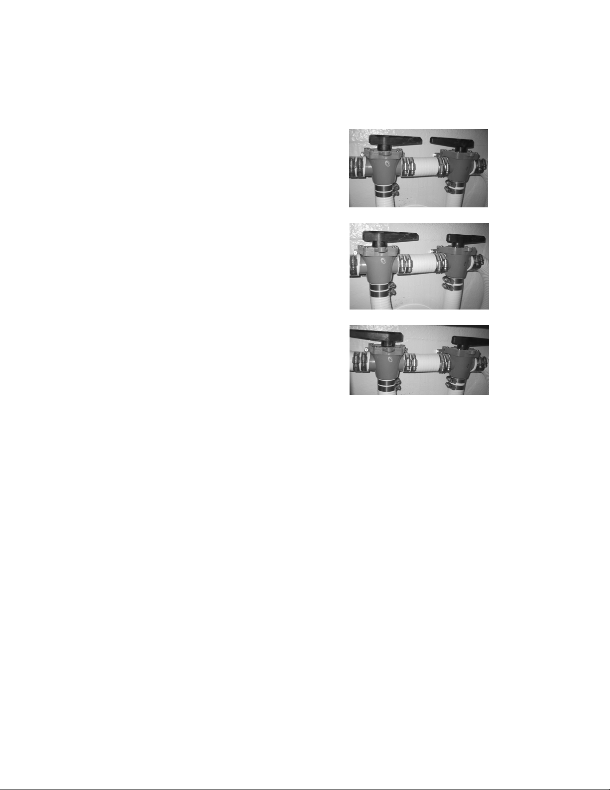
pumps into the holding tank.) Below are all the possible valve configurations for the toilet:
* See overview illustration on page 11
Overboard
Into Holding Tank
Gravity Drain Holding Tank
Holding Tank
The holding tank is located directly behind the toilet
and is on the same level as the sail locker base. The
holding tank is 18 gallons with a 1 ½" inlet at the top
against the outside of the hull. The 1 ½" outlet is at
the bottom against the outside hull. The vent is on
the same side with a ½" hose going across the tank
to a through hull fitting under the sink. The holding
tank can be inspected visually through the Plexiglas
bulkhead in the sail locker. It may be necessary to
shine a flashlight behind the toilet from the other
side of the tank to illuminate the fluid at the same
time.
In the top of the tank is a 4" inspection cover. The
tank can be inspected by unscrewing the top shelf in
the sail locker. The tank can be removed through the
sail locker by cutting the marine sealant tabbing that
holds the vertical Plexiglas wall below the shelf in
the sail locker.
Combination Shower Pump /
Bilge Pump System
Your new Gemini 105Mc comes with an upgraded
9 Copyright © 2004 Performance Cruising Inc.
Page 10

Gemini 105Mc Owner’s Manual
Plumbing, Head, & Water Systems
shower and bilge pump system which enables you to
get “double-duty” out of the Gulper 220 pump. This
powerful pump is capable of pumping 12’ of head,
can be run dry without damage, and transfers about
1 gallon of water per minute.
The pump is located under the port dinette and is
accessible from the cabinet door closest to the
head. Through the use of the two diverter handles
located on the outside of the cabinet, you can convert the pump to act either as a shower bilge pump,
or as a port or starboard bilge pump. There are two
6’ section of hoses housed in the same cabinet as
the pump (on the port side) and in the corresponding cabinet on the starboard side. You can move
the end of these hoses to the area of the boat you
would like to pump out and even add a hose extension to reach the cockpit lockers.
Configurations:
The two-way diverter handles enable the following
selections:
Diverter 1 – one end of handle always points to Di-
verter
1. Pump from Starboard Bilge
2. Pump from Port Bilge
winter when the hoses were stiff. They can be tightened with a screwdriver or 5/16 wrenches.
Cockpit Shower
It is possible to tap into the cold-water hose just
after the pressure pump and run a hose to the aft
deck for a shower.
Salt Water Pumps
A flipper-type pump that is compatible with salt water can be installed in the galley counter. A 1/2"
through hull can be installed below the starboard aft
bunk.
Diverter 2 – one end of handle always points to
Pump:
1. Pump from Shower
2. Pump from Bilge (Port or Starboard)
Mains Water Adapter
It is possible to fit a Mains water adapter on the aft
deck and run a hose to just after the pressure pump.
However, if this is done the mains pressure must be
reduced to prevent damage to the ships hoses. This
option is not available from the factory.
Water Makers
Provision has been made for the installation of a
modular water maker around the starboard aft water tank under the starboard aft bed. The water
intake can be easily installed under the aft bed.
Hoses and Hose Clamps
The water hoses used are reinforced plastic, suitable for drinking water and to take hot water.
The hoses are secured with clamps to the various
attachments. These clamps may need tightening
periodically, particularly if the boat was built in the
10 Copyright © 2004 Performance Cruising Inc.
Page 11
Gemini 105Mc Owner’s Manual
Plumbing, Head, & Water Systems
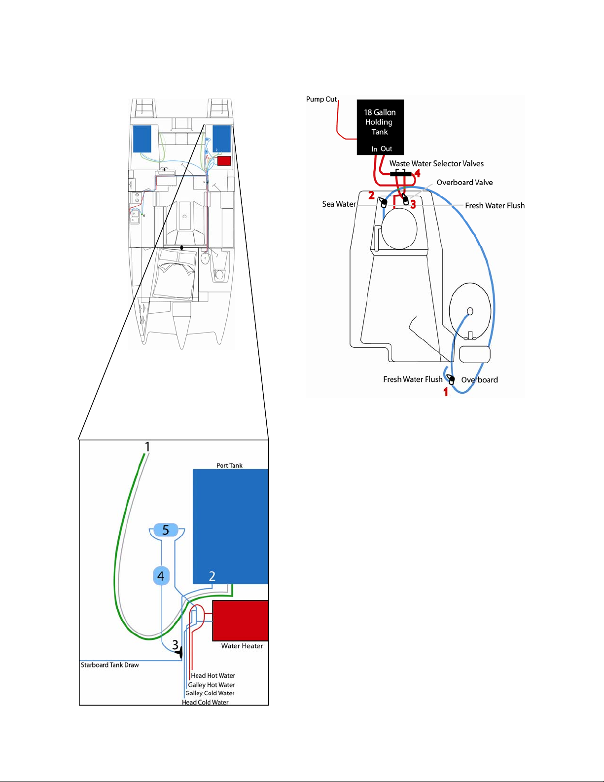
Figure A
Figure B
1. 1 ½” Water Fill Hose and ½” Vent Tube
2. Water Draw from Tank
3. “Y” Valve Tank Selector Knob
4. Particulate Water Filter
5. FloJet Water Pressure Pump
1. Sink Water Valve: Controls where the sink water
drains to. Turning the lever to the right drains
overboard. Turning the lever straight up closes
the valve. Turning the level to the left drains the
sink to the fresh water flush line.
2. Seawater Valve: Controls toilet water intake. With
the lever to the left, the seacock is open to the
sea for flushing with sea water. Turning the lever
upright is the closed position. Turning the lever to
the right opens to the fresh water line for flushing
with fresh water.
3. Toilet Exhaust: Controls the toilet discharge.
Turning the lever upright (inline with the hose)
opens the seacock. Turning the lever down closes
the seacock.
4. Waste Water Selector Valves: Controls the destination of toilet water discharge. See photos and
explanation on previous page for possible configurations.
11 Copyright © 2004 Performance Cruising Inc.
Page 12

Gemini 105Mc Owner’s Manual
Propane System
Propane System
Propane is recognized by most yachtsmen, as well
as the Coast Guard, as the best fuel for use on
boats. It is the easiest to obtain, economical, and
has more heating per pound than natural gas. In
terms of safety, propane will only explode if there
is a ratio of between 12,000 and 65,000 parts per
million of propane and air. There are three major
built-in safety systems to minimize any risks associated with the propane system:
• Flame Failure Overrides
• Xintec Propane Detector and Solenoid
• Propane Pressure Gauge
Although propane is odorless, an identifying odor
(mercaptan) is added so the gas can be readily detected. Should a propane leak ever occur, the odor
is easily detectable at very low levels and overwhelming at just 600 parts per million. Each pro-
pane bottle contains 20 pounds of propane and
takes a long time to escape from a bottle in the
event of a broken pipe. This is unlike gasoline
which, with a small spill, instantly evaporates to an
explosive mixture.
Always store the propane bottles in the cockpit
locker on the bridge. The locker contains ventilation ports down through the bridge deck.
Xintec Propane Control Panel
The Xintec Propane Fume Detector and Control System consist of two detectors located in the aft cabin
of each hull, the Control Panel mounted on the switch
panel, and the solenoid in the propane locker.
When the 12-volt Xintec Detector ‘Gas Valve’
breaker is first turned on, the propane detector goes
through a checking system and stabilizes with a green
light over the number of each sensor on the control
panel. The Xintec detector requires 200 milliamps to
operate. Pressing the left hand end button on the
Xintec control panel marked 'Solenoid', switches the
solenoid open. There is a loud click in the propane
locker when the solenoid opens.
In the event the detectors determine the existence of
3000 parts per million of propane fumes (25% of the
lower explosion point), the control panel will sound
an alarm and automatically close the solenoid which
cuts off the propane to the entire boat.
The Xintec owner’s manual has complete instructions
on system use and maintenance.
Propane Tanks
There are two (2) 20 lb. vertical bottles with a 5 year
rust protection and overfill protection. Note: New,
unfilled tanks are delivered with compressed air and
must be purged the first time they are used.
The pressure gauge is an essential safety feature
and is the first thing connected to the valve on the
bottle. The gauge does not indicate the level of the
gas in the tank; weighing the tank determines the
amount of propane in the bottle. The pressure
gauge provides easy and frequent leak testing of
the LPG system. After using the system and turning
off both the refrigerator and stove, and turning off
the gas at the bottle, the system should hold the
same pressure for at least 10 minutes. The pressure reading will vary depending on the ambient
temperature. Warmer temperatures will cause the
pressure reading to increase while colder temperatures will lessen the system pressure.
There is a separate and continuous copper line
from the propane junction to both the stove and
the refrigerator. There are no joints in the lines
except at the appliance.
Each appliance has a flame failure cut out. In the
event the flame is extinguished on either the stove
or the refrigerator while the unit is still in the “on”
position, the cut out system stops the propane from
flowing to the appliance.
A rubber tube connects to the fitting that has a pres-
sure regulator. There is a special left-hand thread
that is first screwed into the bottle to connect the
tube and regulator.
Propane Junction And Solenoid
The rubber hose coming from the regulator is connected to the solenoid and solenoid by-pass. The
solenoid bypass is intended for use when sailing with
no method of charging the batteries. The solenoid,
which takes (1) one amps per hour to keep open, can
be turned off. This system enables using the solenoid
when the boat is on shore power and when there is
the likelihood that the boat may be unattended. If
the propane is turned on, which would be the case for
a live aboard, and there were to be a leak, the propane detector would shut off the solenoid. When sailing, the boat is attended and therefore any leak
would be detected by either the odor and/or the Xintec alarm and the propane could be turned off manually at the tank. The bypass is opened by turning the
lever in line with the pipe that is bypassing the solenoid.
12 Copyright © 2004 Performance Cruising Inc.
Page 13
Gemini 105Mc Owner’s Manual
Propane System
Carbon Monoxide
When propane burns with a blue flame, only carbon
dioxide and water vapor are produced. However, a
yellow flame is an indication that carbon monoxide
is being produced. Carbon monoxide can also be
produced if there is a 5% depletion of oxygen in the
cabin while propane is burning.
All internal combustion engines produce carbon
monoxide. A gas engine is worse than a diesel engine. The largest cause of carbon monoxide poisoning is from gasoline-powered generators because
they are left running for long periods of time.
Propane units, if properly maintained, will not pro-
duce carbon monoxide. Proper maintenance includes keeping the system clean and maintaining
good airflow. If you are at all nervous, you can try a
carbon monoxide detector, but unfortunately these
detectors are not 100% reliable and can be affected
by atmospheric conditions. In addition, carbon monoxide detectors have to measure the time exposure
as well as the amount of carbon monoxide. Thorough ventilation is the best safeguard against a
build-up of carbon monoxide.
Copper and Fittings
The copper in use is 3/8", K type. Most of the copper
fittings are connected to the various appliances with
3/8" flare fittings.
Checking for Leaks
To check for propane leaks all the line connections
should be tested. With the propane on, use a small
paintbrush and liberally coat the joints with a mixture of dishwashing soap and water. A leak is identified by bubbles in the solution generated from the
escaping propane.
Stove
The stove is an English unit with 2 burners, a broiler,
and an oven. The unit includes a flame failure device
to each burner so that if the flame were to blow out,
after about 10 seconds the heat sensor beside each
burner will cool down and the propane will automatically cut off.
To light each unit there is a flame failure override
procedure. In the case of the stove turning the knob
counterclockwise to full “ON” and pressing the knob
in allows propane to flow. Light the propane and
hold the knob in for a few seconds This warms up the
heat sensor and the unit will continue to run. Completely turning the knob counterclockwise turns the
flame up. To turn the flame down or off, turn the
knob clockwise.
Oven Setting Fahrenheit
1 230º
2 266º
3 302º
4 338º
5 374º
6 410º
7 446º
8 482º
Refrigerator
The refrigerator provides 4 cubic feet of storage
space and a freezer compartment in the top. The
refrigerator is completely silent when operating. The
refrigerant uses ammonia, water and hydrogen and
operates through an absorption process. The application of heat acts like a pump and starts the process.
Heat applied by a small propane flame or an electric
heating probe boils ammonia out of the solution of
ammonia and water. Air circulating over the fins of
the condenser removes heat from the ammonia vapor to cause it to condense to liquid ammonia from
where it flows into the evaporator. After taking heat
from the refrigerator, the ammonia returns to the
reservoir near the bottom of the refrigerator, remixing with the water.
This system is especially suitable to the Gemini as
there is minimal heeling so the reservoir stays at the
same level as the point where the ammonia is boiled
out of the solution. With excessive heeling, the ammonia would not cycle through the system. This
type of unit is very reliable and efficient. Any failure
is normally associated with switches or the thermostat.
Running the Refrigerator
Press the AUTO button to the “Down” position which
illuminates the “Auto” light indicator. If shore power
is available, the unit will select A/C operation. If
shore power is not available, the unit will automatically switch to propane operation. Within 45 seconds, the burner should ignite and operate normally.
If the “Check” indicator light comes on, the control
has failed to light the burner on propane. To reset
when the “Check” light comes on, press the main
power button to the “Off” position and then “On”
again which re-initiates the automatic lighting procedure.
On the initial start-up, after switching propane bottles, or if the refrigerator has not been used in a
13 Copyright © 2004 Performance Cruising Inc.
Page 14

Gemini 105Mc Owner’s Manual
long time, it may take several attempts for the refrigerator to prime itself with propane and light correctly. You may reset the unit as many as four times
to purge the air from the propane lines and light the
burner. This is normal.
The shut down the refrigerator, press on the “On”
button so that it is un the “Up” position—which is
“Off”.
The refrigerator temperature is controlled by a factory preset and cannot be adjusted manually.
While waiting for the interior of the refrigerator to
cool, the only way to know if the unit is correctly
working is to feel the chimney flashing on the back
of the unit. The chimney flashing is accessible
through the ventilation hatch in the cockpit. The
flashing will be warm to touch when the refrigerator
is correctly operating.
* For an in-depth description of how a propane
refrigerator works, turn to the back of this manual.
Running the Refrigerator on 110v
Propane System
To run the refrigerator on 110 volt,
IMPORTANT: When leaving the boat, turn the re-
frigerator to the “OFF” position first then turn the
propane off at the bottle. Reversing these steps,
while not a problem, will burn out the propane in
the line and make re-lighting the refrigerator an
unnecessarily long process as the gas line will need
to re-prime.
The refrigerator is vented to the cockpit. Fresh air
comes in through the hatch near the cockpit floor.
The hot air is then vented out through openings
above the steering wheel. An additional chimney
vents to the top of the canopy and can be opened or
closed with the included cap.
The refrigerator operates most efficiently with a
thorough through-flow of air. Always keep the ventilation hatch open and turn the 12-volt refrigerator
fan on when the refrigerator is running.
When leaving the boat for long periods of time, reinsert the refrigerator air intake hatch cover.
14 Copyright © 2004 Performance Cruising Inc.
Page 15

Gemini 105Mc Owner’s Manual
Shore Power
Shore Power
The Gemini is wired for 110-volt shore power with a
30 amp current rating. The female plug on the combing behind the mainsheet traveler is 30 amps. We
suggest the use of a 50 foot shore power cable. Take
care to keep the cable clean, dry, and in good working order to avoid arcing between the plug prongs.
Caution: While rated for 30 amps, the shore power
plug should not have more that 24 amps running
through it continuously.
The color codes of the wires are:
Black: Live
White: Neutral
Green: Ground
The 110v circuit panel with breaker is just inside
the main door to port. The top of the panel has a
green light to indicate power coming into the boat.
A red light is located just below the green light and
will light if the external power source is incorrectly
wired. If the red light comes on, unplug from the
shore power outlet and try another outlet.
The top 2 switches are the main inlet switches rated
to 30 amp.
The switches under the main switches have differ-
ent ratings up to 20 amps.
Power Inverters
Power inverters transform battery supplied power
known as direct current (DC) into Alternating Current
(AC). An inverter is not available as a factoryinstalled option but can be installed by a trained
marine electrician.
An inverter/battery charger must not be used when
the boat is connected to shore power. Today’s inverter is designed to take the shore power into it so
that it can sense if the shore power is on. Today’s
inverter is so quick that if there were to be a failure
on the incoming shore power the inverter would
switch over to battery without a computer failing. If
a high demand shore power item is installed such as
air conditioning that would take more power than
the inverter is capable of supplying, then a separate
line from the inlet should go to that appliance bypassing the inverter. This is because the inverter
would try and supply the power necessary to run that
appliance if there were to be a shore power failure
and would keep over heating and shutting down.
When testing electronic equipment, be careful that
stray fields from the shore power cables do not influence sensitive equipment.
The wire used is 3-core, 10 gauge, 600º stranded
marine-grade cable.
Switch
Port Outlets (2)
Starboard Outlets (4)
Refrigerator
Water Heater
Air Conditioner / Spare
There are duplex outlets in the head, master cabin,
galley, refrigerator area (close to main door), and
navigation area. The outlet by the navigation area is
ideally suited to plug in a battery charger.
The outlet in the navigation station and master bedroom are GFI outlets. The navigation station outlet
protects the head outlet while the master bedroom
outlet protects the outlet in the galley.
Before connecting the shore power cord, always turn
the AC circuit breaker “Off.” Once connected,
switch the breaker “On.” Similarly, always remember to turn “Off” the AC circuit breaker before disconnecting the shore power cable.
Rating
10 amps
15 amps
20 amps
15 amps
20 amps
15 Copyright © 2004 Performance Cruising Inc.
Page 16
Gemini 105Mc Owner’s Manual
Air Conditioning
Air Conditioning
Power Requirements: 110 Only
Starting: 24 Amps
Running: 15 Amps
The Gemini has an optional Mermaid 16,500 BTU
air conditioner with reverse cycle for use on shore
power only. The unit is installed in the seat housing below the switch panel. The Mermaid air conditioner fan is set to a fixed speed and cannot be
adjusted.
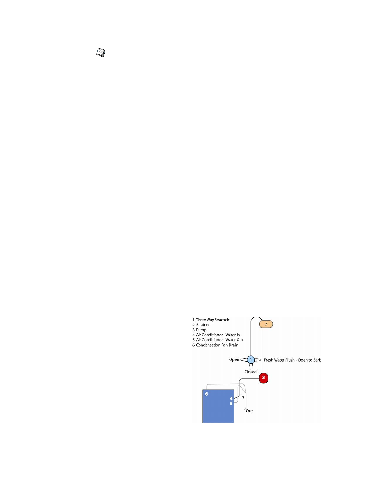
The air conditioner cooling water lines and strainer
must be primed with water prior to turning the unit
on. By opening up the seacock to let water in, the
system may prime itself. If the lines and water
strainer do not fill entirely with water, it is necessary to complete the prime by opening the strainer
lid slightly until the strainer fills with water. Remember to tightly close the strainer lid after it fills
with water.
When turning the unit “ON”, switch the thermostat
to “COOL” and then press and hold the “down”
button on the thermostat to change the thermostat
setting to a temperature below the ambient temperature. Next, turn on the air conditioner by flipping the breaker “On.” After the unit starts, the
first thing to check for is the sound of the cooling
water exhaust coming from below the bridge deck.
The sound is audible from the back steps on the
transom. If you do not hear the water exhaust,
turn the unit “OFF” and correct any problems before restarting.
Most problems associated with the air conditioner
are the result of an insufficient prime, a clogged
strainer, or a kink in the water lines. To clean the
strainer, simply unscrew the strainer lid, then take
out the strainer and clean it thoroughly. Don’t forget to replace the strainer before restarting the
unit. Kinks in the cooling lines are possible following working on the water, heating, or air conditioning systems. Take care to see that all lines are free
of obstructions or kinks.
tioning unit and operate as usual.
Yet another means of priming the system is to dis-
connect the cooling water “in” line from the air conditioner and turn the system on. Wait until the
pump primes itself and a small “geyser” of water
comes from the hose, then quickly reconnect the
hose to the “In” line on the air conditioner.
The air conditioning condensation pan is located
under the unit and drains along with the system’s
cooling water.
To avoid losing the system’s prime while sailing, we
recommend closing the three-way seacock before
sailing.
Reverse Cycle—Heat
During colder weather, the air conditioning unit can
be used in reverse cycle for heating. To engage the
reverse cycle, switch the thermostat to “Heat” and
turn up the temperature setting higher than the ambient temperature. Read the owner’s manual for a
complete description.
Winterizing the Air Conditioning System
The air conditioning unit should be included in the
winterizing process by filling the lines with a 50/50
mixture of fresh water and coolant. Simply place
one end of a standard hose into a one-gallon bucket
containing the mixture and connect the other hose
end to the flushing seacock. Next turn the seacock
to the flush position. Prime the system with the
coolant mixture by unplugging the pump from the air
conditioner and connecting to a 110v extension cord.
The system will use the entire gallon of the coolant
mixture.
Air Conditioning System Overview
Caution: If the system is insufficiently primed and
cooling water is not running through the system
there is the risk of freezing the air conditioning
coils. Should this happen, wait until the coils have
thawed before you again attempt to prime the
lines.
Alternatively, the system can be primed by turning
on the pump alone – without turning on the air conditioning unit. To accomplish this, you will need a
110v extension line to plug in to. Unplug the water
pump from the air conditioner and connect to the
extension line to prime the lines. Once the system
is primed, return the pump plug to the air condi-
16 Copyright © 2004 Performance Cruising Inc.
Page 17

Gemini 105Mc Owner’s Manual
12 Volt Power
Batteries
The Gemini comes with (3) three batteries #24 Deka
Deep Cycle Marine Batteries. There is room for (1)
one additional battery.
The batteries are number 24, deep cycle with a
capacity of 85 amps each. On the battery switch,
“Battery One” refers to two batteries connected
together while “Battery Two” refers to the singular
battery.
A Note on Deep Cycle Batteries: Unlike conventional car batteries, deep cycle batteries hold a
charge better and retain an almost constant voltage
until just before the battery dies. However, in retaining an almost constant voltage, it is difficult to
tell how much charge is left in the battery. The
only accurate way is with the use of a hydrometer
to check the acidity of the battery fluid. Battery
managers that measure the flow of current into and
out of the battery are good for continuous use but
do not work well if the boat is left for long periods
of time without use. Batteries lose charge by internal degradation at the rate of as much as 1/8 ampere an hour. As batteries are used, the distilled
water changes to sulfuric acid and eventually the
formation of sulfate crystals coats the plates in the
battery and the capacity of the battery is reduced.
For example, if the battery is left at 60% charge for
long periods of time, then the battery will not accept a charge of more than 60% while charging. It
is possible to tell when the battery is near dead
when it can be fully charged in a short time.
Solar power is an efficient way to keep batteries in
good condition as solar power puts out low current
at high voltage. The solar panel, available as an
option, charge at up to 10 amps per hour.
A battery can be charged to 80% easily but the last
20% of charge requires a lot of time so that the battery is not overheated. That is why running the
engine to charge the batteries is not efficient no
matter what capacity alternator is in use.
The new smart chargers require a thermometer on
the battery.
Gel cell batteries are expensive and can be damaged by over heating and theoretically can only be
charged and discharged one quarter as many times
as deep cycle batteries.
Checking Battery Levels
Deka recommends checking the electrolyte fluid in
your batteries weekly and/or before any prolonged
battery charging, such as extensive motoring.
Checking the batter level simply means ensuring
the electrolyte is filled to the indicator line on the
battery case (which covers the plates). If the bat-
tery needs fluid, use only distilled water. To go a
step further, you can use a hydrometer to test for a
specific gravity of 1265 following a charge. Start
with the cell closest to the (+) terminal. The specific gravity reading should be between 1.100 and
1.300 (Specifically 1.265).
Be sure to keep the battery connections clean as this
will help ensure longer battery life.
Battery Monitors
Battery monitors measure everything that goes in
and out of a battery through the negative side. This
is a highly effective way of keeping track of available
power. A voltmeter is not accurate enough as it will
not tell you what state of charge your battery is in.
Battery Switch
The battery switch is located above the batteries.
Caution: Never switch from position “1” to position “2” through “OFF” – especially when the engine is running as damage to the alternator could
occur. Always switch through the “BOTH” position.
With Battery “1” selected on the battery switch, all
12 volt power is coming from the first set of batteries and only the first set of batteries are receiving a
charge from the alternator with the engine running.
Battery “2” is not in use. When battery “2” is selected all 12 volt power is coming from the single
battery and the single battery is receiving a charge
from the alternator with the engine running.
If battery “1” is used and left fully charged before
switching to battery “2”, then there will always be a
full spare battery and vice versa.
The Gemini does not make use of a designated engine starter battery as the smaller Westerbeke engine does not require a large amount of current to
start. In addition, a designated starter battery requires the use of an automatic switch. With an automatic switch, once the engine is started, first the
engine battery is fully charged and once it reaches
13.8 volts then the other ship’s batteries are
charged. The problem with this system, as discussed
earlier, is that it is easier to charge a flat battery
17 Copyright © 2004 Performance Cruising Inc.
Page 18

Gemini 105Mc Owner’s Manual
than a fully charged battery. A yachtsman who does
not use the engine for an appreciable amount of
time may never put any charge into the ships battery and of course there is some degree of inefficiency in the switch.
25 Amp Fuse
There is a 25-amp fuse between the live red 8-gauge
wire going up to the switch panel and the battery.
This fuse with a spare is down beside the battery.
There is no fuse between the battery and the en-
gine because in the event of a short at the engine
the battery cables are so large that the battery will
quickly die before the cables over heat and cause a
fire.
Individual components are fused as necessary.
Solar Panel (Optional)
12 Volt Power
18 Copyright © 2004 Performance Cruising Inc.
Page 19
Gemini 105Mc Owner’s Manual
12 Volt Power
Wiring Code
The standard code for 12-volt is red positive and
black negative. Unfortunately the boat cable supplied sometimes comes red and black and sometimes white and black. We have chosen:
BLACK = NEGATIVE
RED OR WHITE = POSITIVE
Note that the color coding is different to shore
power where black is live and white neutral.
The European system is different and electronic
equipment that comes from Europe has the code:
BROWN = POSITIVE
BLUE = NEGATIVE
Switch Panel
The switches on the two 12-volt panels are also
circuit breakers and vary from 5 amp to 20 amp.
See table below.
VHF Radio
The VHF is recessed into the switch panel above the
12-volt panel. Consult the included owner’s manual
for information on operation.
Stereo AM/FM/CD
The Gemini 105Mc now comes standard with an
AM/FM stereo CD player with two speakers mounted
on the main bulkhead. Consult the included owner’s
manual for information on operation.
Cabin Lights
The Gemini has three (3) fluorescent lights in the
main cabin over the galley, navigation station, and
saloon table. The fluorescent bulbs take an extremely low power draw and are intended as task
lighting. Each light draws 1/3 amps. Note that fluorescent lighting is known to sometimes interfere with
VHF reception. Turning off the light corrects VHF
reception issues.
There are also six (6) 12-volt incandescent dome
lights, each located in the head, master bedroom,
each aft cabin, over the refrigerator and in the cockpit. Each light draws 1 amps. Red bulbs can be installed to maintain good night-vision.
Replacing Light Bulbs
Individual bulb specifications are subject to change.
When replacing a bulb, always remember to have the
original bulb with you when buying a replacement.
Related Topics:
See Mast Wiring on following page.
Switch
Compass Light 5 Red light to illuminate compass at night
Masthead Lights 10 For sailing at night— 25 watt tri-color masthead light
Anchor Light 5 For anchoring—10 watt masthead light
Instruments 5 Backlight for TriData, AutoHeml, and instrument panel
Fans 15 Optional Fans — Includes through-flow refrigerator fan
Shower Pump 15 Also operates port and starboard bilge pumps
Deck Lights 10
Cabin Lights 20 Includes both fluorescent and incandescent
VHF 15
Gas Valve 20 Turns power on/off to Xintec Propane Monitor
Stereo/TV 15 Turns power on/off to AM/FM Radio / CD Player
Spare 20
Heater 20 Optional heater
Running Lights 5 For motoring at night
Rating (amps) Purpose
19 Copyright © 2004 Performance Cruising Inc.
Page 20

Gemini 105Mc Owner’s Manual
Mast Wiring
Mast Wiring
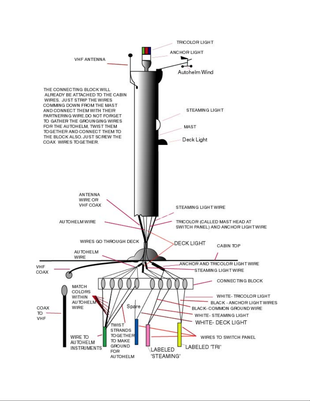
After the mast is erected, the wires in the mast are
routed through a 2-inch tube. These wires terminate
in the roof of the master cabin and are accessible
behind a removable panel.
Mast wires connect as follows:
The coaxial cable for the VHF is screwed to the coax-
ial cable that terminates at the radio by the switch
panel.
The wire from the electronic equipment is con-
nected color to color either side of the connecting
block supplied. The ground wire is a few unshielded
strands of wire that should not be ignored, but attached to connecting block as shown in the illustration.
There are 3 twin core wires coming from the switch
panel one labeled 'steaming' and the other labeled
'tricolor and spare'. These are attached to the connecting strip.
The twin core wire labeled 'steaming' has its individ-
ual wires labeled:
White:
Steaming
Match the wires to their partners based on color
through the connecting block. Do not forget to
group together and connect the ground wire
strands.
Most of the 12-volt wires in the coax are under the
roof molding. There is little chance of failure with
the wiring except for the connections to the various
pieces of equipment. All the connections are accessible.
The 12-volt wire used is 16 gauge 600º boat cable
wire (The 110 volt wires are 3 core and mainly under the dinette).
Masthead Lights
The masthead lights are supplied with the mast
from Selden Masts. Selden has been known to
change the make of the masthead lights without
warning. At present (2004) , the light is an Aqua
Signal masthead light. The bulb specifications are
as follows:
Anchor Light: 10 Watt (Part SW40)
Masthead Light: 25 Watt (Part TDH40)
Black:
Ground or negative for all three lights up the mast.
The twin core wire labeled tricolor has its individual
wires labeled:
White: Tricolor
Black: Anchor (this is the only time a black wire is
live supplying power to the anchor light)
The twin core labeled spare only uses white for deck
light. (The black is spare)
From the mast there are two sets of wires:
1. Brown and blue from the steaming light partway
up the mast. The brown is the positive to the steaming light and the blue is the negative.
2. Brown, blue and strip yellow from the combina-
tion tricolor and anchor light at the top of the mast.
The blue is the negative to both anchor and tricolor,
with the brown being the positive to the anchor and
the yellow being the positive to the tricolor.
3. Brown and blue from the deck light. Brown is
positive and blue is negative.
The wires from the Autohelm wind are connected to
the instruments through the connecting block.
20 Copyright © 2004 Performance Cruising Inc.
Page 21
Gemini 105Mc Owner’s Manual
Mast Wiring
21 Copyright © 2004 Performance Cruising Inc.
Page 22
Gemini 105Mc Owner’s Manual
Mast Rigging
Mast and Rigging
The Gemini 105Mc mast is 39’ off the deck and the
bridge clearance is 46’
The mast is deck stepped and sits on the main bulkhead. The main bulkhead is 3/4" teak ply, increased
to 2 ¼” thick under the mast.
The mast is a double spreader rig with the shrouds
coming down to the main bulkhead. The chain plates
are slotted through the deck and bolted to the main
bulkhead. There are steel straps that transmit the
load down to the bridge-deck.
The slotting of the chain plates through the deck is
the strongest system but requires periodic maintenance. As the chain plates take load and stretch, the
seal can break. There is a stainless cap that is loaded
with silicone sealant. Simply re-caulking the chain
plate will solve any leak problems.
Like most modern sailboats, the Gemini’s mast is
relatively light to reduce pitching and improve performance. When a light section is used it is necessary
to use double or triple spreaders. Most race boats
will use running backstays to keep the mast straight.
With Gemini, in place of running backstays there are
permanently mounted check stays and a baby stay to
the lower spreaders
The cap and lower shrouds are 7mm (9/32”). The
intermediate, baby, check, and back stays are 6mm
(7/16”). The 7mm stays use a 1/2” turnbuckle while
the 6mm stays use a 7/16” turnbuckle.
The backstay is a single 6mm stay (33.36’ from center pin to Delta plate), with a 15 foot 7/32” bridle
going to each transom. The tensioning device slides
down the lower bridle pulling the bridles together,
tensioning the backstay.
Tensioning the backstay tensions the headstay which
is needed for windward work.
Caution: Leaving the backstay under permanent tension would damage the boat. Slack off the backstay
when not in use for upwind work.
Tensioning the Rigging
If the Gemini 105Mc is commissioned at the Perform-
ance Cruising factory, all the rigging is tensioned
before handover and should not need adjustment
until such time as the tension has been altered
through extended use. Typically, the rigging tension
should be checked as part of the 6 month maintenance schedule.
We recommend the use of a tensioning gauge for
adjustments to the rigging. Both sets of cap, intermediate, and bottom stays are initially tightened by
checking the number of threads visible at the base of
each stay. Following initial tightening, the following
details, in order, the tensioning on each of the stays.
It is important to adjust the stays in order:
Stays (In order of
tensioning)
Back Stays (6mm)
Cap/Top Stays (7mm)
Intermediate Stays
(6mm)
Lower Stays (7mm)
Baby Stay (6mm)
Check Stays (6mm)
Tension in
Kilograms
*
440
320
440
*
*
Tension in
Pounds
*
970
705.2
970
*
*
* The back stay should be tightened to the point
where all slack is eliminated but with no bow or
bend in the mast. The check stays are present only
to eliminate mast pumping and are tightened to the
point where there is just a small amount of slack.
The baby stay should be tight enough to put a small
pre-bend in the mast so that when the Genoa pulls
forward in heavy wind, the mast straightens up.
The halyards are low stretch ropes with shackles.
The rope is 3/8" or 7/16". The halyards are internal
for the main, jib and topping lift.
There is provision for a second internal jib halyard
and a crane for an external spinnaker halyard. To
use a spinnaker there needs to be a lower halyard to
support the spinnaker pole, and a pad eye to fix the
spinnaker to the mast approximately 2' up from the
base.
The masts are delivered with a combination anchor \
tricolor light on the top of the mast, a steaming light
2/3 of the way up the mast, a deck light 2/3 of the
way up the mast, coax for a VHF antenna and an
aluminum tube in the mast with a feeder line to pull
through the wires for the mast head instruments.
The masthead unit of the wind instruments is drilled
and tapped to the top plate, facing forward.
On the side of the mast at the base are pads at the
right angle and position for bolting on two single
speed winches, one for main and the other for the
jib.
The gooseneck is riveted to the mast 24" up, with
hooks on either side for slab reefing.
When setting up the rigging, the most important
point is for the mast to be straight with all the side
shrouds set to the same tension. Beside a tension
gauge, the best way to test for equal tension is to
pull the shroud 6' up. With about 40 lbs. of pull the
22 Copyright © 2004 Performance Cruising Inc.
Page 23

Gemini 105Mc Owner’s Manual
Mast Rigging
shrouds should move about 2".
The checkstays do not need to be tight at all be-
cause they only serve to stop the mast from pumping
when beating to windward. For racing, the clevis pin
securing the turnbuckle to the pad eye can be replaced with a quick release 3/8 pin, for down wind
disconnection.
The mast is normally set vertical. Moving the mast
does not seem to affect the helm.
With the Gemini 105Mc the mast is raised 1’, includes a 1’ crane on the top, and the boom is extended 1’ compared to older Gemini models. (The
older masts were 38’ off the deck; the 105Mc mast is
39’ off the deck)
The forestay meets the mast at the 38-foot mark
leaving a foot above it for the optional “roller
screacher”, which is basically a roller-furling drifter.
This is an excellent option for the cruiser that doesn’t want to bother with a spinnaker in light airs. The
screacher option includes supporting hardware consisting of a mounted track that curves from one bow
to the other across the bowsprit. The base of the
sail can travel over the track and be brought to
windward.
there is no means of feeding the lines without them
crossing.
The boat comes standard with lazy-jacks. On the
underside of the boom are two padeyes at 5-foot
increments. A 12-foot line goes between these padeyes either side of the boom and is attached to a
line that goes to a pulley 5 foot below the upper
spreader on the mast. These single lines go back
down to cleats by the boom. With this configuration, the lazy-jacks can be tensioned by the cleat or
removed when sailing.
The main sail has also changed with this 105Mc mast.
The crane provides for a much larger mainsail and
helps in obtaining maximum drive out of the top of
the sail. With this crane we can have a large roach
mainsail. However, so the sail doesn’t get caught up
in between the backstays, there is a single backstay
with a tensioner about 15’ up. The backstays only
need to be tensioned during up wind work and should
be slack at the dock.
Boom
The boom is 15ft. long and is secured to the mast at
the gooseneck with a clevis pin. The boom has three
pulleys at the stern end and three jam cleats at the
underside of the boom at the gooseneck end.
The starboard pulley and jam is for the first slab
reef. The second pulley is for the out-haul. The third
pulley is for the second reef. The sail that comes
with Gemini has slides on the foot so that the end of
the slab reefing line can be tied around the boom.
The first slab reef is between the second and third
slider from the end while the second slab reef is
between the fourth and fifth slider from the end.
The main sheet goes to a triple block shackled to the
under side of the boom. On the mainsheet track on
the combing is a slider with a triple block, becket
and jammer. The main sheet runs to the triple block
with the becket and jammer on the center pulley,
23 Copyright © 2004 Performance Cruising Inc.
Page 24

Gemini 105Mc Owner’s Manual
Engine, Drive Leg, Fuel
Engine
The standard Gemini 105Mc engine is the Westerbeke 27 horsepower, Model 30B. The 27-hp diesel is
linked to a sonic outdrive leg and provides excellent
fuel economy and battery charging from the 55-amp
alternator.
The use of diesel is safe and can be used for other
appliances on the boat such as heaters and generators. This engine weighs about 400 lbs. The fuel
economy will range from 6 to 12 miles to the gallon
depending on speed and conditions.
The Westerbeke engine is mounted on the bridge
deck under the center cockpit hatch. The gearbox at
the back of the engine is connected through a flexible coupling to the Sillette sonic out-drive leg. The
engine is accessible through all three cockpit lockers
and aft deck hatches.
The oil dipstick, oil filter, and water pump are located behind the starboard side breakaway panel.
Access to the port side is by unscrewing the side
panel. Please refer to your Westerbeke manual for
oil change information and specific operating instructions including service periods.
The 30B engine uses about 3 1/8 quart of SAE 10W30 weight oil. The transmission uses about 7/8
quart of the same type oil.
Refer to the back of the manual for an addendum
and for how to contact your closest authorized
Westerbeke Service Center.
Cooling Water
The cooling water for the engine comes into the ship
through a seacock under the starboard aft bed. The
seacock has (3) positions: In from the sea, closed,
and a third position which enables connecting a hose
to the open barb on the seacock for winterizing.
There is a water filter by this seacock. The engine is
a freshwater-cooled engine with salt water-cooling
the freshwater in a heat exchanger. There is a fresh
water header tank on the wall above the engine.
Gear Lever / Throttle
The Gemini 105Mc comes with a single lever throttle
and gear control (UFlex
Engine Control)
wheel. With the lever in the neutral position, the
handle can be pulled out 1/4" to disengage the gears
so the throttle can be operated without moving the
boat.
located on the starboard side of the
B73 Single Lever Top Mount
Once the lever drops back to the neutral position,
which is vertical, the gears are engaged. Pushing the
lever forward 45º engages forward. The rest of the
movement increases the engine speed. Moving the
lever back engages reverse.
Fuel Tanks / Gauges
The Gemini 105Mc has (2) two 18 gallon fuel tanks,
each located either side of the engine under the aft
deck. The fuel gauges are located on the instrument
panel. There are (2) two fuel selector valves located
under the engine hatch on the center stern. One is
fuel supply to the engine. The other is the return
valve returning the unused diesel fuel back to the
tank. The valves simply point to the tank in use.
Both valves should point to the same tank.
Following the fuel valves is a glass Racor fuel filter
on the rear wall. Following the fuel filter, the fuel
goes to the engine electric pump and then to another fuel filter. The Westerbeke uses an electric
pump and is self-priming.
Diesel fuel in tanks can grow a fungus, akin to a
black sooty deposit. This deposit can block the
hoses, filters, pumps and injectors. Even a filter will
not help resolve the problem as the hoses leading to
the filter can get blocked. To stop this potential
problem, a diesel additive can be added to the fuel.
Diesel fuel is also subject to water condensation. It
is advisable to leave the tanks full to reduce the
occurrence of water condensation.
Hot Water and Cabin Heater
Just inside the engine compartment are (2) two 3/8”
black hoses that connect to a brass junction with a
valve. Continuing from the brass junction are two
(2) 5/8” hoses. Each hose connects to the hot water
heater and the optional cabin heater.
With the valve at the junction in the horizontal position, fresh water from the engine is heating the water in the water heater. With the junction valve
vertically down, the water supply is shut off.
With the optional cabin heater there is an additional
valve in the port aft cabin under the bed. This valve
can open the engine hot water to the cabin heater as
well. The optional heater is the Heater Craft 500H
unit capable of 28,000 BTU.
Sillette Sonic Drive Leg
Please read through the Sillette manual thoroughly.
The sonic drive leg will provide many years of dependable service if used correctly and properly
maintained. Improper use can result in breakage.
Slamming the leg down into forward with the full
throttle before the leg has locked into place can
cause damage. Always bring the leg down in a slow
and controlled manner and do not throw the throttle
completely forward until the leg clicks into place. If
24 Copyright © 2004 Performance Cruising Inc.
Page 25

Gemini 105Mc Owner’s Manual
Engine and Drive Leg
the boat is in particularly choppy water, take care
to lower the leg slowly as there may not be enough
water to fully cushion the leg when dropping into
place.
The sonic drive leg includes a metal claw that goes
over the thrust bar. The claw is held down by an
inverted "L" shaped lever and allows the engine to
reverse without coming up. A knob in the starboard
cockpit locker pulls the “L” lever forward. Once
this lever is moved forward the claw can move up
off the thrust bar and the whole drive leg can be
raised out of the water.
In lowering the leg to prepare for use, the claw
pushes the spring loaded inverted "L" lever out of
the way so that the claw can go over the 7/16"
thrust bar. The spring loaded "L" lever then clips
back over the claw preventing the sonic drive leg
from rising while in use.
As part of the standard maintenance schedule, be
sure to keep the claw and “L” lever well coated
with marine-grade grease for proper operation.
Should there ever be a problem raising the drive
leg, the lock claw can be opened manually by pressing down on the lever with a boat hook and then
raising the leg as usual. Be sure to then thoroughly
grease the claw to regain proper operation.
Raising the Leg
1. Place the small red lever next to pump handle
in the horizontal position, in line with the flow
of hydraulic oil.
2. The black knob must be tightened or closed.
3. Pull out silver reverse lock knob on back wall of
locker.
4. Pump handle to begin raising the leg – you may
release the silver lock knob after leg begins to
rise.
5. Turn the small red lever vertical - this will lock
the leg up in case of a leak in the pump seal.
Lowering the Leg
1. Turn the small red lever to the horizontal position, in line with the hydraulic line.
2. Loosen the black knob on the pump and the leg
will drop into place. You should hear it lock
into place.
3. If the boat is still moving forward as the leg is
lowered, it likely will not lock into position as
it drags through the water. In this case, with
the engine running slowly move the throttle
forward and out of neutral. As the prop engages, you will hear the “click” as the leg locks
into place.
Steering the Drive Leg
With the drive leg in the “down” position, lines from
the 8-inch tiller on the rudders go tight to the pad
eye on the top of the drive leg. The drive leg is then
steered in line with the rudders. With this configuration, you are directing the thrust in the same direction as your rudders which provides for a very
responsive, maneuverable boat.
Specific instructions for how to remove and replace
the oil drain plug on the leg are included in the
addendum of this manual—refer to the back of this
manual.
MK II Cat Spare Kit Available for Order from Performance Cruising includes:
$186.00 + Shipping (Check Only)
(1) CVJ gaiter
(2) Pair Prop Seals
(1) Transom Oil Seal
(1) 17-spline tab washer
(1) ¾ x ¾ DU bush
(2) ¾ x ½ DU bush
(1) Grease Nipple
(1) Latch Spring
(2) 7/16 A2 washers
(1) Drain Plug
(1) Transom Anode
(1) Prop Shaft Anode
(2) 1/8 split pin
(2) 3/32 split pin
(2) ¼ UNC x ½ SKT cap
(2) ¼ UNC x ¾ SKT cap
(2) ¼ UNC x 1” SKT cap
(2) 5/16 UNC x ¾” SKT set
(1) Loctite and Instant Gasket
(1) Keenol Grease
(1) Spare Parts Price List
(1) Sheet of Reminders for Gemini Owners
Send check or money order with a reference to the Drive
Leg Spare Parts Kit to:
Performance Cruising Inc.
7364 Edgewood Road
Annapolis MD 21403
Propeller Specifications
15” Diameter / 11” Pitch
17 Spline Drive
3 Blade Aluminum— Left Hand
25 Copyright © 2004 Performance Cruising Inc.
Page 26

Gemini 105Mc Owner’s Manual
Centerboards and Rudders
Centerboards
In terms of performance, the centerboards are Gemini's secret weapon. Fixed keels, which are used in
most cruising catamarans, are a detriment to windward ability, down-wind speed, and draft, which
dangerously lowers the center of buoyancy and affects their offshore ability and storm survival. In
addition, fixed keels that increase the draft to 3’
have to be engineered to take striking an unseen
rock without sinking the boat whereas centerboards,
with their pivot at the front, simply push up when
they strike a rock. Daggerboards are the most efficient, but, are not a cruising option because when
they hit something they have to break.
On the Gemini, there is a centerboard in each hull.
The centerboards are on the outside of each hull 7"
off center to give foot room in the hull and to keep
the centerboard slot to one side of the keel so that
stones are not forced into the slot when grounding.
The top of the centerboard case is level with the
working surface in the galley and navigation station.
The centerboard winch handle socket is in the wall
of the galley and navigation station.
The Gemini 105Mc has asymmetric foam cored fi-
berglass centerboards as opposed to the older
wooden boards. These boards yield remarkable performance and are incredibly strong. Unfortunately,
for best performance using asymmetric centerboards, only the leeward board should be used. This
necessitates continuously changing the board when
tacking.
The drawbacks to centerboards are that they need a
long slot. As this slot is narrow, the boards must also
be narrow. The narrowness of the boards has a tendency to create turbulence on the low-pressure side
of the board. Designing a centerboard shape to
overcome this tendency is a challenge.
With experienced design, Gemini’s' centerboards
create minimal turbulence and do not affect the
interior accommodation. They are less accident
prone than any other cruising catamarans with vulnerable fixed keels, and because they can be used
one at a time, getting rid of the parasitic drag of the
windward keel, they are dramatically more efficient
than low aspect ratio fixed keels.
Operating the Centerboards
The centerboards are 7' long with the pivot 6" back
from the front of the case in line with the main bulkhead and level with the floor. When the centerboards are fully down the leading edge is approximately 45º back and the exposed centerboard is in
the shape of a quadrant or fin coming out of the bottom of the hull. Most of the slot is still filled with
centerboard; this prevents turbulence and gives a
strong bearing surface. The centerboards go down 4’
below the keel.
There is a 3 1/2" solid PVC drum inside the case up at
the top, 2' back from the front of the case. 3/8" rope
is connected to the top front of the centerboard. The
rope then comes back across the top of the centerboard under a bolt and then up to the drum. When
the centerboard is up, the rope goes approximately
one turn round the drum on the outboard side,
through the drum to the inboard side (where it is secured) then round the drum an additional 3 turns.
From the drum it then goes under the bolt and back
to pad eyes on the top of the centerboard.
Inserting a winch handle in the socket and turning
the drum counterclockwise approximately 1 3/4 turns
lowers the centerboard. Turning clockwise raises the
centerboard. You will know the board is completely
up when raising once you hear the board bump
against the top of the case.
The centerboard is held in position by sliding a 1 1/4"
wing nut over a 3/4" nut behind the winch handle
socket. Clockwise turning of the wing nut jams the
drum to the side and prevents the board from moving.
The direction of rotation is such that if the centerboard was down and it struck bottom it would push up
and simply undo the locking nut.
Centerboard Maintenance
The Gemini’s design calls for very little tolerance
between the centerboard and the centerboard case.
As such, the boards are designed to be in the water
only when necessary. When not necessary, raise and
lock the boards in the “Up” position. If the boards
are left in the water for prolonged periods, growth
will occur on the board’s surface and make raising
impossible until the board has been cleaned.
The centerboard pivot is visible on the floor side and
accessible from behind the case. In the event of a
leak the pivot can be tightened a little. 3M 5200 is
liberally used to seal around the pivot and at worst
can be resealed. The boat should be taken out of the
water to do this. In over 800 boats we have found that
pivot leaks are rare.
The mechanism in the case at the top can be reached
by unscrewing the cap. The rare problems that can
happen are for the rope to slip off the drum. This is
near impossible because bolts hold the case together
around the drum leaving nowhere for the rope to go.
It is very rare for the rope to break. This rope can be
changed with the boat in the water. The winch
socket, shaft, and drum can also be changed with the
boat in the water.
26 Copyright © 2004 Performance Cruising Inc.
Page 27
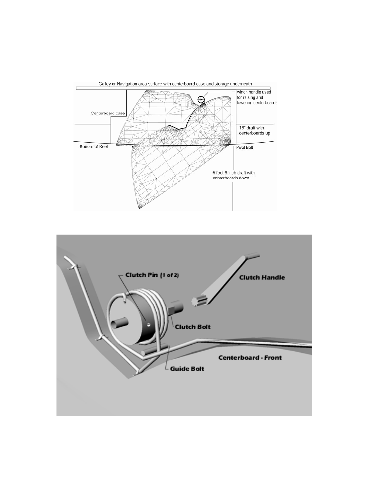
Gemini 105Mc Owner’s Manual
Centerboard Design
Centerboard Clutch Assembly
27 Copyright © 2004 Performance Cruising Inc.
Page 28
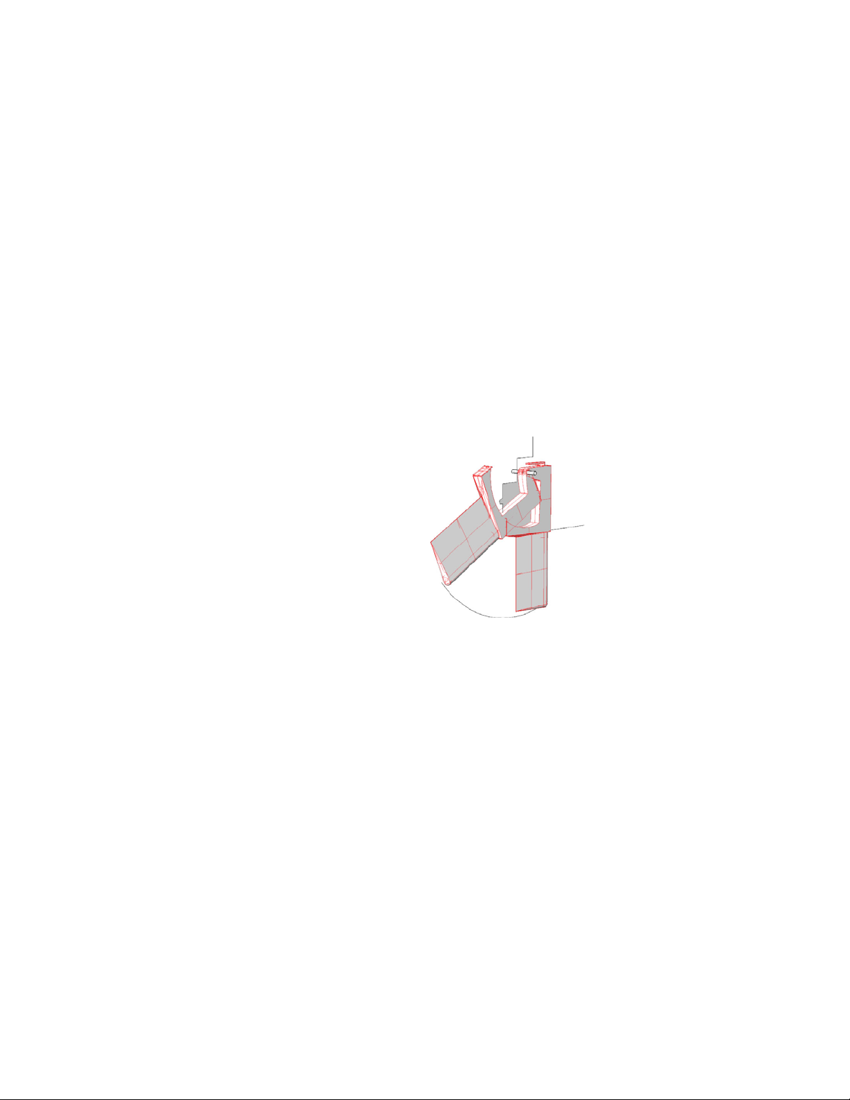
Gemini 105Mc Owner’s Manual
Centerboards and Rudders
Performance and Use of the Centerboards
The centerboards are only needed when sailing to
windward with apparent winds closer than 70º. From
experience we have found that only the leeward
board is necessary. In fact the boat is ½ knot faster
with only the leeward board down. The rationale is
that the leeward hull is the hull doing all the work,
whereas the windward hull is parasitic drag. Having
the keel down on the windward hull will simply increase the drag of that hull. Having discovered this
it was necessary to increase the size of the centerboards so that only one had sufficient area to prevent leeway.
For leisurely sailing use both boards 1¼ turns down.
However, if the boards are down, and they do not
need to be, then the lack of side pressure may cause
the boards to rattle in the slot. Simply raising them
eliminates any rattling. The boat will sail at any
angle with no boards. However tacking is more difficult and the boat will slip sideways when sailing
close to windward.
In light air, it is more difficult to sail without the
centerboards in the “Down” position. In heavy airs
the leeward hull makes a good keel as it is pushed
down into the water. In fact, in rough conditions it is
advisable to slightly raise the centerboard to take
some stress off it when punching to windward.
The technique to changing the boards for maximum
efficiency when beating is to lower the windward
centerboard before the tack when the hull is slightly
raised, and the leeward centerboard takes the side
pressure. After the tack when the sails are set then
raise the new windward centerboard.
Motoring and Docking with Centerboards
When motoring, the centerboards are not needed
and, in fact will cause drag. However, in preparation
for docking or maneuvering in tight harbors, the boat
is much more maneuverable at slower speeds with
the centerboards in the “down” position. When
docking, especially with strong crosswinds, it is advisable to place both boards in the “Down” position
to stop the boat being blown.
Strong Winds and the Use of Centerboards
When reaching with winds above 25 knots the use of
the leeward centerboard ¾ turn down will steer the
boat straight, reducing the load on the rudders. With
strong winds there are big seas and it is these seas
that can cause a problem as the boat tries to broach
when the leeward bow digs in. Of course with the
boards up on a broad reach the boat will travel perhaps 14 knots, which is also putting stress on the
rudders. Lowering the leeward centerboards part
way reduces the top speed perhaps to 12 knots but
the reduction of stress on the helmsman is worth it
as the boat is much more responsive.
Offshore Use of the Centerboards
Offshore with larger waves the centerboards can be
used less. In fact, offshore it is possible to sail up to
50º without the use of the centerboards.
In survival conditions raising the centerboards will
allow the boat to slip sideways away from breaking
waves.
Rudders
Like the centerboards, the Gemini’s rudder system
has uniquely beneficial engineering. The rudders on
Gemini are a spade rudder glassed to a 1 ½" solid
rudderstock, with a permanently fixed 8" tiller that
faces aft. There are two split rudder-bearing molds
that are riveted around the rudderstock. These bearings are filled and faired, then painted.
There is a ¾" hole in the
back top of the rudder
bearing and the rudder
recess also at the top
back. After the rudder
and bearing assembly is
inserted into the rudder
case recess, a ¾" stainless
tube is inserted in the ¾”
hole. This ¾" tube is part
of the Uflex steering system.
The Uflex steering system has a double head with
two individual cables. The port steering cable is 19’
while the starboard steering cable is 14’.
The outer ends of the inner cable have a stainless
rod that passes through the 7/8" tube at the rudders.
The outer cable is secured to the 7/8” tube. The
7/8” tube is threaded with 1 5/16” nuts to lock it
either side of the rudder case. The stainless rods are
connected to the tiller by means of a link arm. In
this way, as the wheel is turned one rod pushes one
tiller while the other rod pulls the other tiller. This
is a totally balanced system, better than a single
cable going to one rudder that is not good in compression but good in tension.
Rudder Usage
The rudders should always be all the way down even
in light airs. Part way up, the slot is opened and that
will cause drag. The sheet stoppers that hold the
rudders down only need the minimum of force just
to hold them down. Too much force will cause the
rudders to stick and not kick up quick enough if the
rudder touches bottom.
28 Copyright © 2004 Performance Cruising Inc.
Page 29

Gemini 105Mc Owner’s Manual
Depending on the amount of usage, eventually it
is necessary to replace the steering cables. Performance Cruising offers step-by-step instructions
on replacing the steering cables on the Owners’
Info Center website. (http://www.mypci.net)
The rudders are raised and lowered by a double
purchase rope pulley system. The operation of the
system is such that the rudders will steer at any
position – up, down, or in between. There is no
increase in tiller loads as the rudders are raised,
unlike most other systems.
The ropes that lower the rudders go through a
sheet stopper. The sheet stopper is made inefficient by the addition of another rope so that if the
rudder hits an under water obstruction it will kick
up. When not moving forward the rudders will
stay down, but when moving forward the rudders
tend to kick up. The sheet stopper prevents the
rudders from raising. However, do not over tension the stopper as the lines could jam and cause
breakage in the rudder system.
Be sure to lower the rudders when leaving the
boat, particularly in deep or choppy water. Leaving the rudders in the up position for long periods
of time causes unnecessary strain on the up rope.
Centerboards and Rudders
There are no holes drilled below the water line so
that even if the whole rudder were to be ripped
from the back of the boat there would be no holes
in the boat unlike any other system.
Access to the rudder mechanism is through the
hatch in the second transom step.
The drive leg is steered by ropes connected to the
end of the tillers that exit the transom by the
bridge deck and are then connected to the drive
leg.
For emergency steering another pad eye can be
fixed to the outside of the hull. With ropes to each
side of the tiller and then the ropes connected
together, a tiller can be connected to the two
ropes that will steer the boat by moving one rope
one way and the other rope the other way.
29 Copyright © 2004 Performance Cruising Inc.
Page 30

Gemini 105Mc Owner’s Manual
Construction
Hull Construction
The hull of Gemini is produced using a large, onepiece mold with no secondary seams or joints. Similarly, the deck is produced from a single mold with
no removable or add-on parts. The centerboard
and rudder cases are each integral to the mold and
have an elaborate air blowing release system. In
this way, the centerboard case and rudder case are
all molded in at the same time as the hull is
molded. This gives a dimensionally accurate, leak
free and strong structure.
The hulls have a high quality Cooks marine gel coat
(953WA411) with a 20mm veil and vinylester barrier
coat. The main lay-up is all done at once, with no
chance of weakness as a result of interlaminate
bonds. The main lay-up is comprised of layers of 24
oz stitched bi-directional woven, alternating with
high stiffness 1 ½ ounce mat. The overlap in layers
increases the strength in strategic places such as
the keel. The keel is strong enough to support the
boat on a point load, and ends up with fiberglass
totaling 5/8" thick with additional wood reinforcing.
The bridge deck has the same lay-up as the hull but
balsa core is also integrated into all flat surfaces.
The reason for using Balsa is because the bridge
deck is flat and subject to heavy pounding loads.
Reinforcing to the hull is by strategic use of bulkheads and interior molds.
Deck Construction
ripped out, much larger than the actual backing
plate. The only time there is a good reason to have a
backing plate is for items that are being pulled at
right angles to deck or hull, such as rudder gudgeons. A backing plate would stop the bolts pulling
through the hull. Unfortunately consideration should
be given as to whether it would be better to have,
for instance, four bolt size holes in the event of a
sudden unexpected load like running aground or a
large hole if backing plates are used. The small holes
can be stopped up easily while a large hole might
sink the ship.
Stress and Movement in Catamarans
A monohull, which is basically a tube, is automatically stiff enough to take the mast and rigging loads.
Of course, the Achilles heel of a monohull is the
enormous point load of the narrow keel, which is
almost half the weight of the boat.
A particularly wide catamaran requires cross arms to
connect the hulls together. These cross arms have
high point loads at connections, particularly when
the boat is subject to twisting.
Gemini is a narrow catamaran and can be considered
as an upside down channel with the flat of the channel being the bridgedeck and the inside hulls being
the walls of the channel. The rest of the outer hulls
just keep the water out. The narrow catamaran with
full cabin is like a box and easily resists the twisting
forces.
The deck is a one-piece mold with all the horizontal
surfaces balsa cored. The balsa core provides a
solid, stable foundation underneath all walking surfaces. In the case of all deck fittings, the Balsa is
replaced with extra glass and plywood to avoid the
possibility of water infiltrating into the balsa core.
The use or non-use of backing plates is often mis-
understood by customers and even some boat builders. An item bolted on that takes sheer such as a
chain plate must not have a backing plate.
The most important design consideration is to have
the materials of such a thickness that they have the
same percentage elongation under the same load so
that the bolts are uniformly loaded. A backing plate
would change the situation and put the entire load
on the first bolt.
Most items on the deck of a sailboat are subjected
to torsion such as the stanchions. The most important design consideration is to transmit the load
over a large area. This is most easily accomplished
by molding in plywood; again simply making the
fiberglass thick also helps transmit the load. Backing plates are academic because a failure would
almost certainly be a large chunk of deck being
As the mast pushes down on the center of the channel, the headstay and backstay pull up the ends. A
channel subjected to high loads can only bend if the
sidewalls deflect out. With Gemini the only signs of
deflection are the side hulls moving up perhaps ¼".
This movement is impossible to eliminate and is definitely a result of headstay and backstay loads and
not side shroud loads. The side shrouds are all connected to the bridgedeck and not the outer hulls.
With the centerboard down this movement is only on
the windward hull because the side push of the centerboard counteracts the outward movement of the
channel side. The windward hull when lifted out of
the water should be assumed to bend down, not up.
This is further proof that the upward movement of
the outer hull is induced by the backstay and headstay loads.
As a result of this upward movement it is not advis-
able to keep the backstay tight for a prolonged of
time. For racing there does not appear to be any
damage if the backstays are tightened to the maximum just for the duration of the windward leg and
then released, provided that the upward movement
of ¼" of the hulls does not damage the door jamb of
the main bulkhead.
30 Copyright © 2004 Performance Cruising Inc.
Page 31
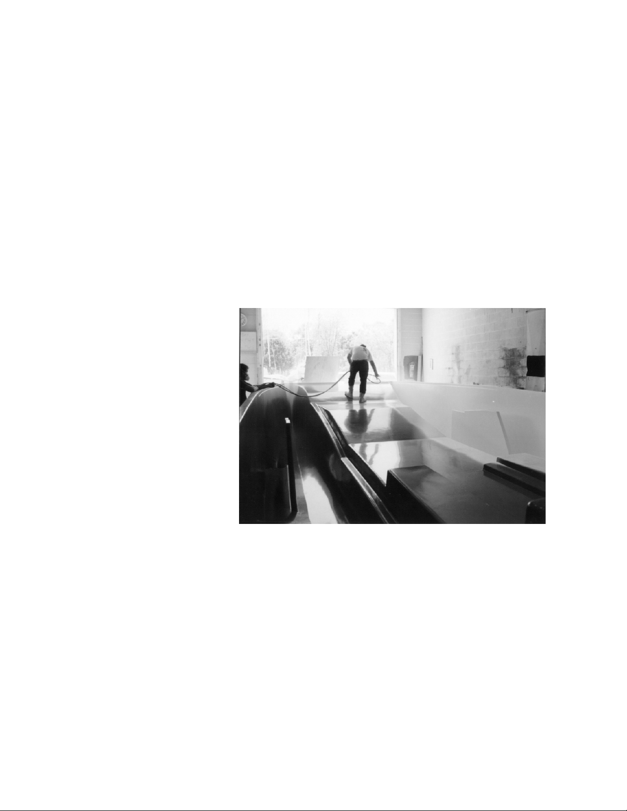
Gemini 105Mc Owner’s Manual
How Gemini’s Construction Differs from a Monohull
A 34’ monohull has a hull area of 350 square feet and a deck area of 250 square feet. Gemini's hull area is 770
square feet and the deck is 600 square ft. The monohull has only one bow and transom and is normally
glassed in a mold that can be tipped for easier rolling out of the fiberglass. With a tipped mold, gravity helps
hold the fiberglass to the now horizontal hull side, and the excess resin can easily be squeezed out. The
whole main lay-up of a monohull is quicker to apply reducing the places where the fiberglass hardens that can
cause air blisters as additional fiberglass is applied over the ridge.
Gemini's hull mold is comparatively huge and cannot be tipped. Not only are there two bows, two transoms,
two centerboard cases, and two rudder cases, but also a bridge deck with many corners. The problems associated with a large, non-tipping mold are that the hull sides are molded vertically making it difficult to apply a
good quantity of resin without it running down the hull sides into the keel. This excess resin is difficult to
remove. Reaching all the places on the bridge deck and around the keels and rudders without air voids and
obtaining a perfect resin\glass ratio is difficult.
The deck is large and it would be difficult to apply two-tone gelcoat. Gemini's deck has a large non-skid pattern molded in. This pattern not only gives a good non-skid surface but also because of the shadows and texture does the same job as adding another color to the deck.
Construction
The molds to build Gemini are also three times more expensive than a monohull of the same size. The extra
surface area of Gemini means that if
Gemini is built with the same lay-up
as the monohull, then Gemini will
be a lot heavier than the monohull,
even with the keel on the monohull
taken into consideration. Fortunately, Gemini does not have to be
strong enough to take the high point
loads of a keel, so can be of lighter
construction. However, the lighter
construction and large surface area
as well as the flexible nature of the
fiberglass make the deck difficult to
handle during construction.
A monohull is normally built with
most of the interior fitted out before the deck is put on. The deck is
also trimmed out with the various
fittings installed before it is bonded
to the hull. Gemini with large light
moldings has to be bonded together first to stabilize the shape. The hull must have numerous interior moldings and bulkheads bonded in before it is released from the mold. This also slows down the process. The unbonded deck is so flexible that it is left in the mold while the entire mold and deck are turned over, then
placed in position over the hull and released. Once the hull and deck are bonded together then the boat is
ready for the assembly shop. Unfortunately, the whole boat has to be finished with workers carrying everything through the main door.
The structure of Gemini is second to none. Any cosmetic problems such as small blisters or stress cracks
could be solved with different manufacturing techniques but the structural integrity of the boat would be
compromised. For example the hulls could be molded separately like a monohull but then there would be a
suspect joint where the parts are joined. Cheap low aspect ratio keels could be bolted on reducing the cost
of centerboards and cases. Cheaper fixed rudders could be used. But those are compromises we are not willing to make.
31 Copyright © 2004 Performance Cruising Inc.
Page 32

Gemini 105Mc Owner’s Manual
Construction
Design Considerations
In comparison to any other cruising sailboat with
the same accommodation, the Gemini is faster,
lighter, has less sail area, draws less water, and
sails more upright. Performance Cruising has built
more than 800 Gemini’s and is constantly refining
the product and manufacturing techniques. As
such, Performance Cruising builds a 34' catamaran
more cost effectively than any other sailboat factory can build a sailboat of similar accommodation.
The conventional monohull has a fixed keel, fixed
rudders, and fixed inboard diesel. This simplicity
makes the boat easier to build and less expensive.
The cheap cast iron keel is the low cost solution to
turning an unstable single hull into a sailboat with a
mast and sails that are trying to tip it over. The
draw back to this keel is deep draft and weight. A
heavy boat needs more sail and a larger engine.
Most people think the keel is a weight hanging under the boat trying to pull it upright. Unfortunately,
with the keel weighing, say 5,000 lbs., and the
loaded hull weighing 11,000 lb., the point at which
all this weight can be assumed to act to bring the
boat upright (the center of gravity), is near the
water line and not several feet under the boat. This
makes for a boat that will tip easily and is very uncomfortable.
The modern fast monohull has a very deep keel
with a bulb, a high-tech light hull, and wide beam.
Interior Molds
The Gemini 105Mc advanced construction includes a
single interior mold encompassing the area from
stem to stern and port to starboard. This interior
mold is unique to the entire multihull industry and
provides a multitude of benefits including enormous
weight savings as well as incredible strength. The
interior mold is built with a wiring harness which
includes 110 volt wires, hoses, and conduit for electronics glassed in before it is structurally glassed in
to the hull. There are also several small accent
molds.
The roof mold is rather light and has 12 volt wire
glassed into position before it is glassed to the
deck. This mold has cutouts to facilitate bolting on
genoa tracks, winches and cabin lights. This mold
also has a glassed in flange to take the main bulkhead.
The refrigerator mold is 7' wide and high and cov-
ers the main cockpit bulkhead. This mold has a box
to enclose the refrigerator and another box for storage or an air conditioner. This mold is glassed into
position and ensures that the refrigerator vents to
the outside. This mold also has the grooves for the
Sails and Sailing
window slider.
The aft cabin walls are large molds that stand verti-
cal to separate the aft cabin. They are bolted into
place after the hull and deck have been bonded
.
Buoyancy Tanks
The Gemini has (4) four buoyancy tanks situated in
each corner of the boat. These buoyancy tanks are
not designed to float the whole boat but to stop a
holed hull from going down too far and allowing
water to flood across to the other hull and capsize
the boat.
These buoyancy tanks are air filled tanks, but are
not guaranteed as fully airtight. They should be inspected periodically to make sure they are dry.
Each tank has an opening inspection port. In the
head, the port is located directly behind the toilet
plumbing. In the aft cabins, the port is located on
the aft cabin stern wall. In the master cabin, the
port is located under the carpeting in the large forward storage locker.
For offshore use, it is advisable to fill the tanks
with either airtight plastic bottles or Styrofoam
chips contained in netting (to make removal easier).
The inside of the tank should be accessible to test
for leaks. As such, it is not advisable to fill the
tanks with permanent foam or any material that
cannot be easily removed.
Leaks
If a leak is detected, first taste the water to see if it
is salty. If it is fresh, the leak is either water from
the water tanks or a topside leak from rain. If it is
salty then it is a hull leak.
The best way to find a hull leak is to completely dry
the bilge and look for telltale trickles of water. It
may be necessary to dry the bilge repeatedly because the first telltale trickle could be from water
trapped behind a bulkhead. The leaks are almost
certainly from a through-hull fitting, so be sure to
check
• Speedo
• Depth sounder
• Toilet through hulls
• Centerboard pivot
• Engine water inlet
• Air Conditioning inlet
A boat in rough seas could have a leak from up high
such, as the gunwale joint, sail locker, anchor
locker, or deck fittings.
32 Copyright © 2004 Performance Cruising Inc.
Page 33

Gemini 105Mc Owner’s Manual
Sails and Sailing
Sails and Sailing
There are three types of sailing rigs: Masthead,
fractional, and rotating.
The rotating rig is the most efficient with the mast
being supported by a single large shackle on the
front of the mast, with the base sitting on a ball.
The mast, which is normally wing-shaped, can then
rotate in line with the wind. The main sail has a
large roach and full battens. The jib is fractional. As
there are no backstays with a rotating rig, it is not
possible to carry a large headsail. The power from
this rig comes from the main sail, which can be
large. The single side shroud must go to a wide base,
which is why it cannot be used on a narrow
monohull. The wide shroud base and lack of headsail
loads gives a low load system but unfortunately the
whole mast is supported at only one position. The
large fully roached main is very efficient.
The fractional rig is the next most efficient rig. The
side supports to this mast can be any system but the
headstay presents a problem. A permanent backstay
can only be attached to the masthead and will bend
the mast when the backstay is tensioned to support
the headstay. Monohull fractional rig boats will have
a crane at the top of the mast to push the backstay
back as much as possible to allow the main to be as
big as possible. Running backstays are necessary to
support the headstay and to prevent the mast bending. Large Genoas are not possible. Multihulls, with
their wide beam, are normally set up like the rotating mast, but fixed. The main sail is large with the
small genoa. Fractional rig boats have a high mast
failure rate.
The Gemini 105Mc uses the masthead rig. The mast-
head rig is the strongest because of the amount of
shrouds that support the mast.
With the rig on the Gemini, we have found a way to
retain the strength of the masthead rig but reduce
the windage and get drive from the top of the sail.
This new technology big head main sail works very
well. The backstays are moved back on a 12" crane
at the top of the mast. The main sail (7 ½ oz cloth
weight) has an elaborate headboard and a fully battened main that goes behind the single backstay.
This rig gives more power and can be used in higher
winds because of the reduced windage and lower
heeling moment.
There is a newly promoted type of rig called the
Cabospar. This is an un-stayed mast with the boom
being continuous around the mast, going forward to
the tack of the jib. The jib is self-tacking, being less
than a 100% jib. Without shrouds to keep the mast
up, there are a lot of localized forces at cabin top.
None of the un-stayed mast boats produced to date
have been promoted as offshore boats.
From experience, once there starts to be any movement in an ocean going situation, this small movement rapidly expands to a serious problem. The
Cabospar rig requires the same effort to set and reef
as a normal rig. This rig will require the same effort
as a normal rig with a self tacking jib when sailing to
windward, will be less efficient on a reach (unless
the sheets are eased like normal rig with a self tacking jib), but will be easier down wind when the rig
can be rotated to be at right angles to the wind easily. Unfortunately, the rig is grossly under-canvased
and spinnakers cannot be used. The rig has a few
unique advantages such as backing up. This rig is
ideal for a Pro.
Main Sail and Reefing
The standard main sail is fully battened and two reef
points. Lazy jacks are included. These sails cannot
be raised or lowered unless the boat is pointing into
the wind. Gemini's pilothouse and the lack of heeling
with wide flat decks makes sail handling easy.
Your 340 sq. ft. main sail is made of 7.3 oz. Dimension Dacron in a relatively soft finish for easier furling. The sail has a large roach and extends beyond
the backstay giving additional area which contributes
to greater speed and pointing angle. The sail has
three full-length battens which support the roach.
These battens are tightened by turning an adjustment screw in the batten-end fittings at the luff of
the sail. The batten should be made tight enough so
that there are no vertical wrinkles across the battened area of the sail. To remove the batten from
the sail, the adjustment screw must be completely
loosened.
The lazy jacks installed on the Gemini mast collect
the main as it is lowered. It is not necessary to
neatly flake the main when storing it. Your main
will come with simple 3’ line sections for sail ties.
There are a number of additional sail tie options
available for purchase at your local marine supply
store. The included sail cover will minimize damaging sunlight and keep your sail in good condition for
years to come.
Should your sail get dirty, you can clean the sail with
standard clothes detergent – making sure to completely rinse the sail afterwards. In the case of
grease, we have found gasoline to be the most effective means of breaking down the grease. The sail
can then be further cleaned with detergent.
33 Copyright © 2004 Performance Cruising Inc.
Page 34
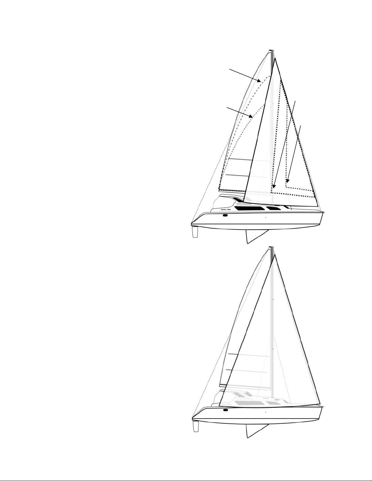
Gemini 105Mc Owner’s Manual
Reefing the Main
Sails and Sailing
To reef the main, let the mainsheet go and slack off
the jib just a little. Leave the rudder turned as if to
tack the boat. The boat will then stop and remain at
about an apparent wind angle of 50º. Hook the topping lift over the winch and down to the cleat to
temporarily raise the boom about 18". Release the
main halyard to lower the main sail until the eyelet
at the front of the first reef point is in line with the
gooseneck. Hook the eyelet over the hook on the
gooseneck and re-tension the main halyard. Pull the
reefing line (blue or red) under the boom until the
back of the sail is pulled down to the boom, and
cleat. Release the topping lift (the reason for raising
the boom is to make it easier to pull the back of the
reefing line to the boom.)
Genoa
Your 320 sq. ft. genoa is made of 5.5 oz. Contender
Dacron. This is an exceptionally tight-weave fabric
and is also a soft-finish cloth making the sail durable, resistant to stretching, and lessens the tendency
to develop wrinkles as a result of roller furling. As an
aid to reefing the genoa, the mid section of the luff
of the sail is padded with a foam insert which helps
keep the sail flat as it is rolled in. The sail has a strip
of Sunbrella cloth on the leach and foot of the sail
which is the longest-lasting sun protection material
available. Reefing the genoa is a simple matter of
pulling on the roller furling line after having let loose
or eased the genoa sheets. Regarding the furling
drum: it is highly advised to leave a small amount of
tension on the furling line (by hand) to ease the sail
out. This ensures that the line will wrap correctly
around the furling drum without any tendency to
foul.
Second Reef
25 Knots
Fourth Reef
Gale
Screacher Sail
First Reef
22 Knots
Third Reef
30 Knots
Spinnaker
For down wind, a spinnaker is essential for racing. A
spinnaker’s lightweight and shape enable the sail to
be blown into a position which captures the maximum drive from the wind with the use of a spinnaker
pole which positions the sail away from the wind
shadow of the main. The spinnakers huge size gives
spectacular down-wind speed. Gemini’s performance
also increases with the lift created by a spinnaker or
full screacher sail.
A single luff spinnaker, which has many names, is
designed for use without a pole. It is tacked to the
base of the headstay like the Genoa, and has one set
of sheets.
Screacher Sail
The optional screacher sail (Dimension Dacron cloth
weight 4 oz) is a 420 square foot roller drifter (200%)
fitted in front of the genoa. The sail is designed
34 Copyright © 2004 Performance Cruising Inc.
Page 35
Gemini 105Mc Owner’s Manual
Sails and Sailing
with a lose luff and permanent curve. This sail
works well on a reach and close to the wind. The
base of the sail is mounted on a curved track traveling between both hulls. For downwind use, the
base of the sail can be moved to windward, lessening the main sail’s wind shadow and increasing
power. For upwind work in light air, the base of
the sail can be positioned amidships.
The screacher lines connect through two snatch
blocks on either side (at the base of the stanchions)
and then to the pad eye on the back of the combing. The snatch blocks enable fine tuning the sail’s
roach for upwind or downwind performance.
To correctly tension the screacher halyard, first
loosen the backstay with the backstay adjuster (if
not already loose). Hand-tighten the screacher
halyard, then re-tighten the backstay. Keep in
mind, the screacher sail has a permanent curve
built in and is not intended to be completely
straightened. Do not attempt to tighten the
screacher halyard using the winch.
The sail is protected from the sun with tedlar film
which is light-weight and offers good UV protection.
However, the tedlar film lacks durability so it is
advisable to lower and stow the screecher if you
don’t plan on using it for a long stretch of time
(more than 2 weeks). The sail furls on its own luff
wire and it must be furled in the direction that
tightens the lay of the luff wire. Furling the sail in
the wrong direction will unlay the wire and possibly
kink and break the wire. To be sure the sail is
furled correctly, check to see that the clear tedlar
film is on the outside of the furled sail.
To lower the sail, center the furling, un-cleat the
halyard at the base of the mast and free the halyard stopper located about 5’ up from the base of
the mast. Slack the sail enough so that you can
easily pull the quick-release pin from the base of
the sail – being careful not to loose the pin overboard. Place the base of the sail into the sail
locker and continue lowering the sail using the halyard.
Reefing
The roller genoa in the full out position has the
genoa sheet going down at approximately 45º to the
slider which is near the back of the track. As the
sail is rolled in, it is necessary to move the slider
forward. The approximate slider position, when the
tack of the genoa is in line with the shroud, is with
the slider level with the checkstay eye. The reason
for the correct position of the slider is to put
roughly equal tension on the leach and the foot of
the sail. This position will change in different wind
strengths. In lighter winds the slider is further aft
putting less tension on the leach, allowing the leach
to fall away and not rub on the shrouds or close up
the slot. In stronger winds the slider is forward to
put more tension on the leach which is being blown
out with the stronger winds.
Suggested wind strength before reefing:
Main Headsail Roller Genoa
Full Main Drifter Full 15 knots
Full Main Genoa Full 18 knots
Full Main Jib First Reef 22 knots
st
Main – 1
Reef
Main – 1
Reef
Main – 2
Reef
Jib First Reef 25 knots
st
Storm Jib Second Reef 30 knots
nd
Storm Jib Second Reef Gale
Wind
Strength—
Apparent
To use the above guide, when the boat has a roller
genoa, simply reduce the sail as indicated above.
The roller genoa is reduced to a jib when the tack is
level with the shrouds and then can be further reduced to storm jib when in line with the baby stay
on the front deck.
As a rule of thumb, consider reefing whenever the
boat heels to 7º or more. An inclinometer will assist
in determining the degree of heel.
Heavy Weather
For offshore use, the catamaran is the safest choice
of boat. The trimaran is the worst followed by the
monohull. To understand what happens in rough conditions and large waves it is necessary to understand
the motion of water in a wave.
In the crest of a wave, water particles are moving in
the direction of the wave with say a speed of 12
knots. In the trough, the water particles are moving
backwards at 12 knots. The water particles move in
a circular motion. Although these waves appear to
be moving, in fact nothing moves, there is just this
circular motion of water. Otherwise the whole of the
Atlantic would end up in Europe in a Gale.
All boats will lay beam to the waves and wind with
no sails up.
In heavy weather, a monohull’s keel can by its own
worst enemy. In the trough of a wave when laying
beam to, the deep keel is in static water, while the
hull is on the surface where the water particles are
moving towards the wave. This starts a pendulum
motion with the boat rocking towards the wave. As
the pulsation of the wave moves on the hull, it is
35 Copyright © 2004 Performance Cruising Inc.
Page 36

Gemini 105Mc Owner’s Manual
Sails and Sailing
then in a water particle moving with the wave.
With the keel still in fixed water the boat will now
rock the other way. This pendulum motion on the
side of a huge wave can cause the boat to drop off
the side of the wave and invert, rolling over 180º.
The catamaran with high buoyancy hulls will not
dig a hull into the trough like a trimaran. The catamaran is also much narrower than the trimaran and
does not have a hull in the middle, which can cause
considerable heeling when punched by a wave. If a
wave punches the windward hull of a catamaran
upwards, because it is nowhere near the center of
gravity, it can only have half the power, and because the boat is narrow, the wave quickly reaches
the leeward hull and pushes that up.
The catamaran does not have the keel of a
monohull and will not trip over it when falling sideways of a wave. The fixed keel catamaran is not as
well off as the centerboard catamaran with the
centerboard up. However, because the fixed, low
aspect ratio keel does not work, this type of catamaran is still better than a monohull for surviving a
storm offshore.
Offshore Cruising and the Gemini
The sea can be a very rough environment. Punching
to windward in 25-knot winds and 15-ft seas for
hundreds of miles is very uncomfortable. When
beating to windward, 2.5 knots is the best any boat
can expect to make to windward. Even if the boat
is sailing at 7 knots, 40 Deg off the wind. At 2.5
knots, with 10 hours of daylight, it is only reasonable to expect covering roughly 25 miles. In these
conditions, eating sleeping and cooking is difficult.
A lot of people will suffer from seasickness. To add
insult to injury, most boats after several hours of
this type of grueling punishment will need attention. 25 knots of wind is not the worst but is deceptively rough and can go on for days. A gale is normally short lived even though the conditions can be
bad. Pulling the sails down will make a gale easy to
cope with. Unfortunately, most people are trying to
get somewhere and do not have time to pull the
sails down in 25-knot winds that last for days. That
is why 25-knot winds on the nose can be the worst
condition.
Because of the horrendous conditions that can ex-
ist offshore and the fact that there is no one around
to help, it is up to the skipper to make sure the
boat is up to the condition that they intend to sail
in. There is no boat built that is suitable to go
straight from the factory into these rough conditions. All boats should be tested thoroughly in progressively worsening conditions. If and when problems occur during the testing, they should be rectified and made stronger. This is not the responsibil-
ity of the boat builder, unless the boat was sold specifically as suitable for offshore racing.
With today’s high tech sailboat, incorrect sailing
techniques will easily break the boat. Running backstays have to be correctly set up along with the rigging; otherwise the mast can easily fail. Today’s
mast is much thinner, which is why boats are faster.
Severe pounding on today’s flat bottom boat will
break them up. Even 65 footers recommend slowing
down when pounding to windward to prevent structural damage. Catamarans with a bridge deck can be
damaged if the boat is recklessly overloaded and
pounded to windward.
Gemini is a boat that is suitable for many uses.
Gemini is built to a price so that the average buyer
who has dreamed of going cruising can follow his
dreams in an affordable package. In addition, Gemini’s design is fully capable for offshore racing. In
fact, the Gemini 105Mc is CE certified for transocean use. However, Gemini is not built specifically
for offshore racing or around the world cruising. If an
owner wants to cruise offshore extensively, then the
recommendation is to take a standard Gemini and
thoroughly test her, and then reinforce the parts
that seemed inadequate during the testing. It must
also be remembered that a boat cannot be suitable
for all conditions. An around-the-world boat will be a
disaster in the light airs of the Chesapeake Bay; she
will have too short a mast and too heavy a sail. An
around the world boat will have few hatches for
safety. This boat will be unbearably hot in the sometimes windless conditions of the Chesapeake Bay.
For racing, Gemini is kept light and will perform
well racing to Bermuda with three people and only
the food and water necessary for the trip. No matter
how rough the conditions, Gemini will not pound the
bridge deck. However, if this same Gemini were to
be loaded for a two year cruise of the Caribbean,
then do not expect to sail to windward in rough seas
and strong wind without experiencing bad
bridgedeck pounding. Overloading the boat does not
make it unsafe. In fact, the boat is probably safer.
The only problem with overloading is bridgedeck
pounding. In this respect, Gemini is no different to
any other cruising catamaran. Catamarans are designed to go over the waves. If they are overloaded
then they try to go through waves, and no matter
how high the bridgedeck, they will pound.
There are three factors that should be considered
for sailing across oceans, and the potential ocean
sailor must have at least one of them. The three
factors are: A large, specially built, ocean going
boat, considerable experience, and/or strength and
fitness. In other words, with the proper boat, an
older, less experienced skipper might make it across
the Atlantic. An experienced delivery skipper can
36 Copyright © 2004 Performance Cruising Inc.
Page 37

Gemini 105Mc Owner’s Manual
probably nurse any boat across the Atlantic. Three
young, very strong men, by virtue of their strength,
can power their way through most problems, and
cross the Atlantic.
Notes on Sailing a New Boat
When sailing on a new boat, particularly in rough
weather, never just sit in the cockpit. Force yourself
to walk around outside and inside to look for possible
sources of trouble. Thoroughly inspect the rigging by
looking for loose cotter-pins or shackles, problems
with the rivets in the mast, and any other hardware
issues. Inside the boat, periodically check under the
floorboards for leaks. If a small puddle of water is
discovered, it is possible to find the source by tracing
back the flow of water. If this leak is left until the
whole area below the floorboards is full, it is impossible to find the source, particularly in a pitching seaway.
Regarding the break-in period associated with the
engine and drive leg; Sillette-Sonic Marine suggests
running the engine up to about 1/2 the engine RPM
for the first 20 hours of operation. This equates to
1500 RPM on the Westerbeke diesel.
37 Copyright © 2004 Performance Cruising Inc.
Page 38

Gemini 105Mc Owner’s Manual
Sails and Sailing
Coast Guard Kit
Gemini is delivered with a Danforth anchor, fenders, mooring lines, and a compass. As most sailors already have some
boat gear, Performance Cruising does not provide a Coast
Guard kit. The recommended items for minimal use are
listed below.
• Charts and Reeds Almanac
• Dividers
• Fire Extinguishers (two mounted, one in each hull)
• Flare Kit
• Flash Lights
• Fog Horn or Bell
• Life Jackets for each Person Onboard
• Spare Anchor, Chain, and Line
• Throw float / cushion
Offshore Kit
To follow is a list of additional equipment for offshore
cruising:
• Radar Reflector
• Solas Flares; red, white and orange
• Safety Harness
• Bilge Pumps
• GPS
• Single Sideband
• Life raft
• Emergency Water and Food in Containers
• Water Maker
• Solar Power
• Storm Sails
• Charts and Reeds Almanac and other local pilots
• Navigation Equipment such as Dividers
• Ships Log
• Hand Bearing Compass
• First Aid Gear
• EPIRB
• Life Sling (man overboard recovery, complete w/
pulley block system to raise man overboard)
• Man Overboard Equipment such as a MOM8, plus life
ring for less serious man overboard situations
• Captains Chair (secured to the floor)
• Foul Weather Gear
• Tool Set
• Spare Parts (including sealants and fiberglass paste)
• Sail Repair Equipment
• Emergency Steering
• Binoculars
• Flash Lights and High Beam Spot Lights
• Bosun's Chair
• Set Flags
• Bucket
38 Copyright © 2004 Performance Cruising Inc.
Page 39
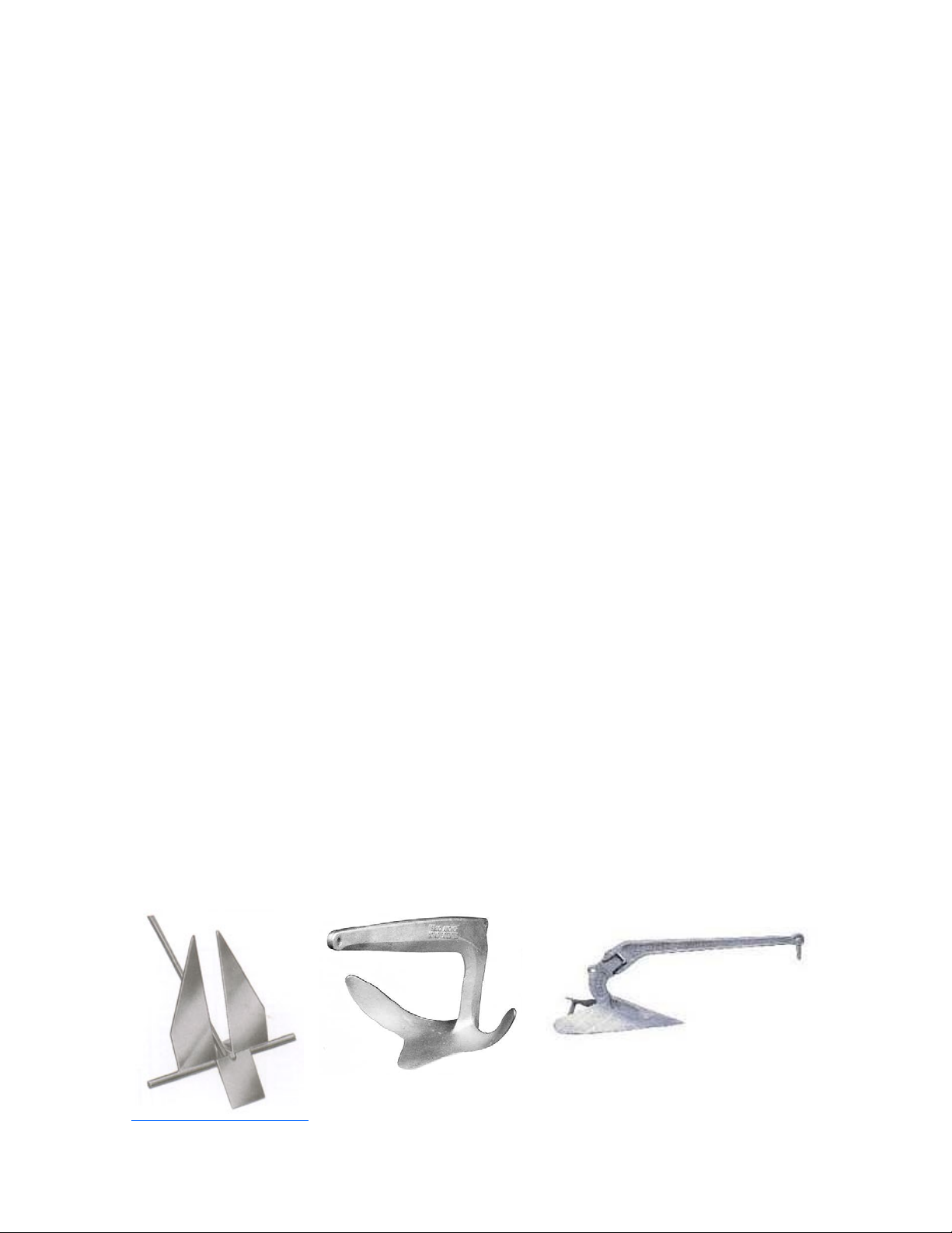
Gemini 105Mc Owner’s Manual
Anchoring
Anchoring
The Gemini 105Mc is outfitted with a 22lb Danforth
anchor supplying 1600lb of holding power. There is
a stowing anchor roller through the bowsprit and an
anchor locker just behind the bowsprit.
Cautionary Notes on Using the Danforth: The Dan-
forth anchor has the highest straight line holding
power but will not take a wind shift. The anchor
can be capsized and released and when loaded with
mud can be difficult to reset if the boat is being
blown fast. The flukes of the Danforth can also be
loaded with grass or kelp and then not hold.
The 22lb Bruce anchor is the strongest but can
develop a ball of mud between the blades and not
hold. The flukes of the Bruce will probably get a
hold in rocks and are strong enough to withstand
breaking.
The 25lb CQR or Harbor Fast from Simpson Law-
rence will plow a circle in the sea bottom in the
event of a wind change. The CQR is a strong forged
anchor but is expensive, whereas the Harbor Fast is
fabricated.
There are other anchors similar to the three above
with different features: The Aluminum Fortress
anchor is like the Danforth but has a high blade
area with light weight. This anchor will hold well,
but because of its light weight will skid across the
seabed if the boat is being blown backwards. The
lighter 13lb Hi-Tensile Danforth has a higher holding
power of 2200lb. This anchor theoretically will hold
more than the standard anchor once it gets a grip
and digs in, but of course, does not have the weight
to hold on a rock or if it gets loaded with weed.
This is a good anchor for racing where weight is a
consideration when sailing.
Setting the Anchor
The standard boat comes with a short length of chain
and 100' of 1/2" nylon rope. This is adequate for normal anchoring in sand or mud. The nylon will stretch
to absorb the shock loads of rough sea. The chain
helps to keep the stock down to make the anchor
plough in. For anchoring in coral where the anchor
line can rub across the coral and get cut, it is recommended that all chain be used. Chain will not absorb
shock like nylon so it is not recommended for other
uses. A compromise is to only use chain that will rub
on the seabed.
While the anchor roller on the Gemini is flared and
rounded at the edges, we still recommend using
some form of chafe guard while at anchor—especially
in rough conditions. The simplest, least expensive
chaffing guard is to simply cut open a 3’ section of
garden hose and wrap the hose around the anchor
line going through the roller. Be sure to also tie off
the section of hose so that it does not simply slip
down the anchor line.
There are numerous theories on anchoring. It is ad-
visable to check into these theories but do not automatically assume that in a bad storm two anchors
are better than one. Unfortunately in a storm there
will almost certainly be a change in the wind direction, at which point the two anchors will wrap together and pull out.
There are several systems for anchoring in confined
spaces to prevent the boat moving down onto other
boats when there is a change in the wind direction.
Anchoring fore and aft is one way. Another way is to
set two anchors facing one another 150 ft or so
apart, and then connecting them together in the
center with a swivel on the sea bed. Finally, take a
line from the swivel up to the boat. In this system
the anchors will not pull out in the case of a wind
shear. Unfortunately, this system will need considerable skill and time to set and retrieve.
Danforth Anchor Bruce Anchor
CQR Anchor
39 Copyright © 2004 Performance Cruising Inc.
Page 40

Gemini 105Mc Owner’s Manual
Gemini only draws 18"and therefore can be an-
chored in much shallower places than most other
sailboats. Anchoring in shallow water needs a lot
less line and is therefore much easier to retrieve.
Normally the scope of the anchor is 7 to 1. In other
words 10 ft of depth will need 70 ft of anchor line.
A useful tip is to thread small colored line through
the anchor line at 10-ft intervals.
Retrieving the Anchor
The solid bridge deck of the Gemini provides a sta-
ble platform for easily raising the anchor. Have the
helmsman drive the boat slowly towards the anchor
with the person raising the anchor giving directions
toward the anchor. The person raising the anchor
only has to flake the loose line into the anchor
locker. As soon as the anchor line goes vertical,
cleat the anchor line and let the forward inertia of
the boat capsize the anchor releasing it from the
seabed. Then simply raise the anchor. Once the
anchor is visible, re-cleat it and let the forward
motion of the boat wash the anchor.
Anchoring
40 Copyright © 2004 Performance Cruising Inc.
Page 41
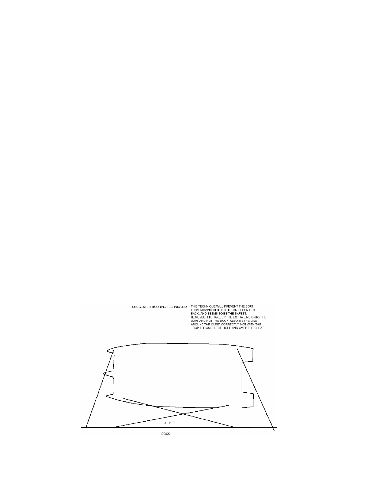
Gemini 105Mc Owner’s Manual
Docking and Mooring
Docking
To secure a boat to the dock, a line from the bow
and stern will keep the boat in. A spring line from
the bow running down the side of the boat to the
dock, and another from the stern also running along
the side of the boat going forward to the dock, will
stop the boat moving backward or forwards. The
lines to the bow and stern holding the boat in should
go to the hull away from the dock so that these lines
are long and can accommodate any rise or fall of the
tide. The stanchion bases are through-bolted and can
be used for additional mooring cleats.
When coming into the marina, have two lines se-
cured to the bow and stern ready to either give to a
bystander or to be ready to take ashore. When the
boat is in position, reverse the lines leaving the ends
tied to the dock with the slack left on board. This
stops people stealing the excess, tripping over them,
or tying another boat with them.
Always make sure that the lines are removable from
one end even if the lines are under tension. Do not
pass the loop of the lines through the cleat. If the
boat is tied to the dock and the tide goes down, the
mooring line needs to be able to be untied slowly
lowering the boat down the wall. At night if the boat
is moving, it is a good idea to be able to retie the
boat while still on the boat, without having to go
onto the dock, which could be dangerous in the dark.
Heaving Lines
Novice sailors sometimes panic as the boat is coming
in to the dock and are often unsuccessful in attempting to throw a line to a dock attendant. The best
method of throwing a line is to simply coil it up, split
the coil and throw half of the split coil. Hold onto
the end of the other half. The weight of the half
being thrown uncoils the half still being held. The
momentum of the half being thrown will then uncoil
that half once the first half has been uncoiled.
Picking up a Mooring
Always approach an open mooring at a slow speed
and note how other boats are positioned relative to
their buoys. The boats will be pointing into the wind
or with the current. Always stay well clear of others’ mooring lines so as not to cut or foul the lines.
In the event that there are no other boats by which
to gauge an approach, pass by the intended mooring
once to gauge the effects of current and wind so
that your approach will be correct.
As you motor up to pick up the mooring, shift into
neutral when the boat has enough forward momentum to reach the mooring.
Have a crew person stand on the bowsprit ready to
pick up the pennant float with a boat hook. Communication between the captain and crew is essential.
It is beneficial to agree on a set of hand signals
rather than yelling back and forth. Do not expect
the person on the bowsprit to be able to hold the
boat in position once in contact with the pennant
float.
If you expect the boat will overshoot the mooring,
shift into reverse or, inversely, shift into forward to
gain enough forward momentum to reach the mooring. Keep the engine running and ready until you are
sure that the pennant eye has been secured to the
anchor cleat. Even after securing the pennant eye,
be careful not to scrape against the buoy.
If you do under or over-shoot the buoy, calmly fall
off and get clear for another try.
41 Copyright © 2004 Performance Cruising Inc.
Page 42

Gemini 105Mc Owner’s Manual
Use of Sea Anchors
Sea Anchors
A sea anchor is without doubt a good addition to a
cruising boat's inventory. When weather conditions
have deteriorated to the point where you just want
to stop, then a sea anchor will keep the boat where
it is. For survival there are certain types of boats
that must have them but for others, the need is
marginal. The boats that race around the world do
not use them. Sailing through a storm is still the
best defense. There are enormous forces in the
anchor line if a sea anchor is deployed in a storm.
Racing trimarans will use a sea anchor to keep the
bow of the windward hull down. The cruising trimaran will use the sea anchor off the bow or stern like
a monohull.
The monohull will use the sea anchor to turn the
boat so that the keel faces the on-coming waves, so
that the boat will not trip over the keel.
One of the biggest problems concerning the use of
a sea anchor is the effect on the boat’s rudders.
The enormous force of a breaking wave over the
bow will force the boat down onto the rudder. If
the rudder turns sideways it is likely to get damaged or ripped off. Anchoring by the stern will protect the rudder. Unfortunately the stern is not designed to take breaking waves and the hatches are
now exposed.
The sea anchor is normally set so that the anchor is
one wavelength away so that the anchor and boat
are in the same water particle movements.
Gemini, in survival conditions, is best just left
without a sea anchor. Pull the sails down, pull the
centerboards up, and turn the wheel so that the
boat will be turning into the waves. If you prefer, a
sea anchor is acceptable if you just want to stop
and do not want to be blown to leeward.
Lightning
The effects of lightning on a boat can vary wildly. If
a boat is going to be completely grounded, everything on the deck must be connected together and
connected to a 12" square steel plate, with 3/4"
bolts. All the equipment used must be capable of
handling 100 million volts, 100,000 amps of current,
and temperatures up to 10,000º centigrade.
Lightning does not travel in straight lines. If it
strikes the boat at the shroud, it will jump to the
next metal object before it will follow the shortest
path through wires to the ground plate. If there is
no grounding on the next metal part, the lightning
will go through the hull to the water. Grounded
boats are struck more often than ungrounded boats.
The main purpose for grounding is to protect people.
The height of the mast gives a cone of protection
with the base the same diameter as the height of the
mast.
In over 800 Geminis, only a very few have been hit
by lightning. People inside one boat reported a loud
bang, all fuses being blown, everything magnetic
demagnetized, some electronics lost, and for the
next year reported strange problems – however there
was no evidence of the actual lightning strike. Another Gemini showed obvious signs of a strike coming
down the backstay and jumping to the rudders. Another had electronic problems and magnetic problems. None showed severe signs of a lightning strike.
In an ungrounded boat, if a Gemini is in the vicinity
of a lightning strike, there will still be a magnetic
pulse induced in metal conductors that will destroy
electronics and demagnetize magnets.
Lightning is normally cloud-to-cloud but occasion-
ally there is a discharge to the ground. When lightning starts from a cloud, instantaneously there are
feeders sent up from all high points on the ground.
The lightning will connect with one of the feeders
and that will be where the lightning strikes. These
feeders need to be a better conductor of electricity
than air. A lightning rod is normally metal, well
grounded to earth with metal strap.
The worst thing to do is to have a badly grounded
boat that will start the feeder lines, but will not be
capable of handling the huge return current. Hanging
starter cables off the backstay into the water is one
example of bad grounding.
If you suspect a storm is coming, turn the radio to an
AM station to listen for static associated with lightning strikes. Listen to the weather reports for the
latest forecast. Watch for distant lighting. Listen
for distant thunder. You may hear the thunder before you can see the lightning on a bright day. Seldom will you hear thunder more than five miles from
its source. That thunder was caused by lightning 25
seconds earlier. The sound of thunder travels at one
mile per five seconds. The best advice when faced
with a lightning storm is to get to shore as soon as is
possible.
Care and Cleaning of Fiberglass
For general cleaning, we have found a cup of Tide
clothes detergent and hot water an effective
cleaner. On average, it takes two buckets of hot
water to clean the boat, each with a cup of Tide.
Spray Clorox is also a good cleaner. Acetone may be
necessary to remove resins, glue, or sealers used to
manufacture the boat. Keep acetone away from vinyl, paint, and the windows. Older gelcoat may de-
42 Copyright © 2004 Performance Cruising Inc.
Page 43

Gemini 105Mc Owner’s Manual
Care and Cleaning of Fiberglass
velop a chalky appearance. Waxes may reduce this
but it is only cosmetic. The gelcoat used on the
Gemini are “buff-back” and can be compounded to
bring the color back. Commercial cleaners are available for removing oil, fuel, and metal stains on the
hulls. Once the stain is removed, the cleaner should
be washed off.
Bottom Paint
Gemini is delivered with bottom paint (Interlux BottomKote Black 779). However, the problem with new
boats is that the fiberglass is new and still releasing
Styrene. It is difficult to get bottom paint to stick,
even with coarse sanding. The procedure we follow
is recommended by Interlux. We use Solvent Wash
202 to remove traces of the mold wax. This is done
using many rags and taking care not to simply dilute
the wax and smear it over the bottom. No-sand
primer is then painted on the bottom. As soon as the
no-sand primer is dry we paint on Fiberglass Bottom
Kote. The bottom is not sanded as that will damage
the gelcoat.
There are two types of bottom paint. Paint with
copper in it at various percentages and a paint that
slowly washes off called an ablative paint. The copper-type paint works well for the first 6 weeks because the copper is at the surface. As the surface
copper dissolves the bottom paint starts to loose its
efficiency. Unfortunately, applying numerous coats is
a waste of time. This loss of efficiency is true of all
bottom paints, even popular paints such as Trinidad.
The ablative bottom paints like Interlux CSC work
well because as the paint is worn off new copper is
exposed. The more coats that are applied the longer
the paint will last. These types of paint will last
many years. We recommend Interlux Micron Extra
5693 Black for the Chesapeake Bay area.
Because Trinidad and Interlux CSC are soft paints
they will fall off easily if the hull is new and still
releasing styrene.
For more information on bottom painting—see the
bottom paint FAQ on page 59 of this manual.
Blisters
Many years ago blisters were probably caused by
inferior, perhaps filled resins. A few years ago a new
problem started. With the explosion of the small
powerboat market, resin and gelcoat manufacturers
started to reformulate their resin for rapid cure.
With these resins a small hull could be gel coated in
the morning and be ready for release in the evening.
Unfortunately, a larger, more complex hull could
take several hours to just gelcoat. The skin-coat
could also take several hours and the skin-coat could
not be applied until all the gelcoat was cured. The
main lay-up would comprise several layers. Normally
all these layers are applied at once. With these
newly formulated rapid cure resins, the molecular
interlaminate bond between the gelcoat and the
skin-coat and then the main lay-up was not as good
as it could be. However, because the main lay-up
was all applied at once, there would be no suspect
interlaminate bond in the main lay-up. If there were
any problems with these boats the problem would be
obvious within two years. Coating with epoxy was a
good cure. It was not advisable to use sand blasting.
Simply removing any loose surface was suitable.
Recently, resin manufacturers have developed pre-
mium gelcoats, vinylester resins, and fine fiberglass
veils. Vinylester resins are the most waterproof.
Gemini has a 20-mm veil with vinylester resin applied just behind the gel coat and has not experienced any major problems with blistering.
However, it must be understood is that there is no
such thing as a totally waterproof resin. Eventually
water will penetrate all fiberglass hulls. It is possible
that as the water penetrates the hull, any impurities
can be dissolved, forming a thick liquid that will expand to form a blister. If this should happen it will
be isolated and should simply be ground out and the
void filled with low-shrink waterproof putty.
The system applied to Gemini from new will start to
loose its efficiency in the first few months and will
need repainting in 9 months. At 9 months, there is
no need to remove the original paint. Simply remove
the barnacles and any growth, power wash, and allow to dry. If any voids are discovered below the
water line, fill with epoxy. If any voids are discovered above the water line, fill with gelcoat paste. If
necessary, lightly hand-sand any white areas and
paint on Interlux CFC right on top of the existing
bottom paint. Paint the centerboards and rudders in
the same manner as the hulls.
We highly recommend keeping up with scheduled
bottom cleaning and painting.
As described in the Construction portion of this
manual, the Gemini is a difficult boat to build. Only
the best materials are used. Applying the fiberglass
to vertical surfaces from several feet away using a 6'
pole on a roller, can produce a situation where there
are air voids between the main lay-up and the skin
or gelcoat. When the boat comes out of the water
for storage or repainting, if there are any air voids
under the gelcoat they will be noticeable as a blister. These blisters should simply be ground out and
the void filled with low-shrink putty. The boat can
then be bottom painted. These blisters are almost
certainly not structural and can be easily fixed.
43 Copyright © 2004 Performance Cruising Inc.
Page 44

Gemini 105Mc Owner’s Manual
Care and Cleaning
Blisters on the Deck or Interior
It is possible that with use, small parts of the gelcoat on the deck or interior may chip away like an
eggshell, exposing a dark void below the skin. These
are not structural and go with the territory of a
hand made fiberglass product. The surface area of
Gemini is 600 square feet with every inch handrolled. When the polyester resin is applied over the
fiberglass mat, because of the initial stiffness of
fiberglass mat, air is trapped below the mat. The
mat is saturated with polyester resin and rolled
with a small metal roller into all the corners. The
air is rolled out from under the mat. If in places the
air is not detected and is left under the mat, the
trapped air is a void that will expand or break out
at some time in the future. There is no way these
voids can be produced with time. All the voids are
there to begin with.
Any voids should be opened out completely and
ground. The surrounding gelcoat should be sanded
with 120-grit paper in a ring 3/4" around the void.
The void can then be filled with a catalyzed
Cabosil/Gelcoat paste. The paste is catalyzed with
2 to 5 % of MEKP liquid catalyst and trowled into
the void. Cabosil is a very fine powder of fumed
silica that magnetically holds together when mixed
into gelcoat. The resulting non-drip paste is very
fine so the cured paste can be polished just like the
original gelcoat.
applied. The factory does not provide the option of
varnishing the interior teak wood.
Window Care and Treatment
The windows around the cabin are made of Lexan®
polycarbonate MR10 with a chemical and scratch
resistant surface. These windows should be washed
with only warm soapy water. The pilothouse window is clear while the other windows are a greysmoked color (Color #2074). Should you ever want to
replace a window, Lexan sheets can be purchased
from your local plastics supplier.
If the film on the polycarbonate is broken, chemicals
will degrade the polycarbonate. Polycarbonate will
expand 1/16" per foot. Therefore an 8' window will
expand 1/2". Fortunately, the surrounding surface
will also expand a little. The expansion can make
maintaining a proper seal around the window difficult. The Gemini’s windows are sealed with a GE or
Dow Corning silicone. The secret to the success of
this material is to get the silicone at least 1/8" thick
between the window and the cabin sides. This is
achieved by creating a silicone dam on the insides of
the screws. Liberal amounts of silicone are applied
between the dam and the edge of the window under
the window. The excess silicone is wiped off, and
previously applied masking tape is removed leaving a
straight line with the silicone tapering out from the
window.
Unfortunately, as the paste cures it shrinks
slightly; so either excess paste is applied or the
void is filled level three times after hardening. This
paste, because it shrinks when curing, is not advisable below the water. The water can enter through
the void left between the shrinking paste as it
cures, and the side of the void. The cured paste is
sanded almost level using 120 grit paper (80 grit is
acceptable providing this paper is only used to remove excess and then 120 paper is used to bring
down close to level. 180 then 360 paper is used to
level and finely sand the repair. The repair is then
compounded to gloss the repair like the surrounding
gelcoat. The reason for sanding 3/4" around the
void before applying the paste is to blend the repair
into the surrounding gelcoat.
Care of Cleaning of Teak
All interior teak on the Gemini is covered with several coats of Tip Top teak oil. The teak oil is applied with a rag and simply wiped over the teak.
The surrounding surfaces are wiped with a clean rag
to remove the excess teak oil.
Mat varnish is another possible treatment for the
teak. This is a time consuming process as all the
teak has to be masked and the surface must be
sanded between coats. At least 3 coats must be
Lexan MR10 Do’s and Don’ts
• Don’t clean with gasoline, Benzene, acetone, or
carbon
• Don’t clean with abrasives or highly alkaline
cleaners
• Don’t ever attempt to clean by scraping with
squeegees, metal, or a razor
• Don’t clean in direct sunlight or highly elevated
temperatures
• Do clean with Joy, Top Job, Windex with Ammo-
nia D, Palmolive Liquid
• If necessary, do remove stickers with kerosene
No maintenance is required for the window seal.
44 Copyright © 2004 Performance Cruising Inc.
Page 45
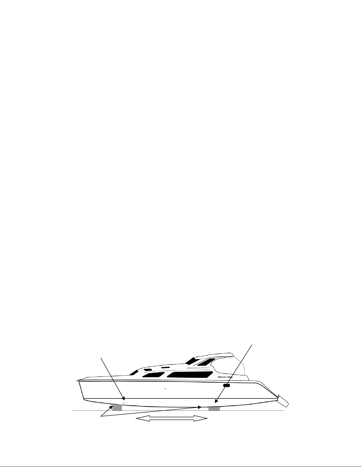
Gemini 105Mc Owner’s Manual
Hauling and Trucking
Hauling and Trucking the Gemini
With the Gemini’s straight keels, hauling the boat is
a relatively easy procedure. The straps of the lift
will go right under both hulls and since the straps
do not stretch there is no tendency for them to
crush the hulls.
Once the boat is out of the water it can simply be
placed on top of four piles of cinderblocks with four
blocks in each pile; making a square pile. The
blocks should be 16’ apart front to back. Place the
front two piles of bricks under the bulkhead at the
back of the buoyancy tanks in the bow. The correct
placement is parallel with a line 4” forward of the
toilet through hull on the port side.
Place the rear two piles under the front edge of the
aft bed. The correct placement is a parallel line 1’
ahead of the outside aft cabin window which is
inline with the bulkhead in front of the aft bunk.
Place a piece of 1” thick plywood about 18" square
(a 2 x 12 cut to 30” running for and aft would be
even better) between the blocks and the hull. Be
sure to bring the bow of the boat down first (until
the straps are loose) and then the stern. When the
stern is about 1” away from the blocks, insert shims
so that each hull is an equal distance from the
blocks. The aim is to distribute the boats weight
over the four blocks evenly. Wedge under the wood
so that the plywood follows the angle of the bottom
of the hull. It is important to evenly distribute the
load over as large an area as possible so as not to
place a point load on the hull.
Trucking the Gemini
At 14' wide, the Gemini can be trucked anywhere far
easier and for less expense than any other cruising
catamaran. However, the transom and rudders must
be lifted above the rear wheels of the truck.
The flat bed of the truck is normally 8' wide but the
keels of each hull are 10' apart. This requires two
large timbers placed on the flat bed for the boat to
sit on. These timbers should be 10" x 12" x 14' long.
They are placed 16' apart on the flat bed. The front
timber will be directly under the bulkhead at the
back of the forward buoyancy tanks. (roughly 6’ back
from the bow) The rear timber will be under the
bulkhead in front of the aft bunks. (located at the
same places as the cinderblocks when storing the
boat) Then a series of wedges about 4" high must be
nailed to the timbers at the sides of the hull to give
additional side support and stop the boat from moving. Place carpet between the hulls and these timbers and wedges to prevent any scratching of the
gelcoat.
Once the boat is in place, use a chainsaw to remove
as much excess wood from the ends of the timbers as
possible. Tie the boat down with lines going from
the four corner cleats diagonally down and back to
the flat bed. This will prevent movement up and
down as well as back to front. The timbers must
also be chained to the truck. Also, to stop the centerboards from hitting the road should they fall
down, take a line from the stanchion above the centerboards down under the hulls to the truck.
Blocking the Gemini
Blocks placed 4”
forward of the toilet
through hull -inline
with the forward bulkhead.
1” thick plywood running
for and aft
Blocks placed 1’ ahead of
the aft cabin window—
inline with the bulkhead
directly in front of the
water tanks.
16’
45 Copyright © 2004 Performance Cruising Inc.
Page 46

Gemini 105Mc Owner’s Manual
Winterizing the Gemini
Winterizing the Gemini involves taking down all the sails
and making sure each of the water lines in the boat
won’t freeze.
To winterize the engine and air conditioner you will
need:
• 3’ section of garden hose with a male fitting
• 4 Quart bucket
• Antifreeze
• Fresh Water
This job is most easily accomplished by two persons. One
person will start and stop the engine while the second
person handles the coolant intake. You can attach a
closing stopcock male connector to the hose end as a
backup to the seacock. Fill the bucket with a 50/50 mixture of fresh water and antifreeze. Attach the hose with
the male fitting to the female receptacle on the threeway engine cooling water seacock. Turn the seacock
handle to the middle position which will draw from the
hose. Place the unattached end of the hose in the
bucket. Starting the engine will immediately start drawing the coolant mixture into the engine lines. As soon as
the bucket is empty, turn off the engine by raising the
silver kill-switch.
Winterizing the Gemini
Winterizing the Air Conditioner
Winterizing the air conditioner is much the same as win-
terizing the engine. Instructions are the same as those
covered in the Air Conditioning section of the manual—
with the exception of drawing from a 50/50 mixture of
water and engine coolant.
46 Copyright © 2004 Performance Cruising Inc.
Page 47

Gemini 105Mc Owner’s Manual
The following operational checklists are for reference only
and may not include all possible actions. We suggest using
these lists as an example to which you can add your own
items.
Operational Checklists
Before Getting Underway
Make sure your registration certificate is visible
or documentation is onboard and available.
Make sure you have charts of the area and com-
pass on board. Check marine weather forecast.
Coast Guard Safety Kit (see page 36) and all
safety equipment onboard in working order.
Make sure engine cooling water seacock is in
the “open” position—check for cooling water in
Turn battery switch to position 1 or 2 and turn
instruments to the “On” position.
Lower one centerboard for slow speed maneu-
vering.
Lower drive leg for motoring—periodically check
and re-grease drive leg lock claw.
Confirm location and quantity of PFD’s for each
person aboard and place throw-able PFD in cockpit.
Check engine oil, transmission oil, coolant, and
fuel levels and visually inspect engine hoses,
belts, and engine bilge.
Before Leaving the Boat
Raise and tighten both centerboards in the full
up position—lower the rudders.
Raise drive leg and close off red valve by the
pump.
Turn the main battery switch to “off.”
Replace sail cover and ensure all hatches, win-
dows, and doors are shut and locked completely.
If leaving for an extended time, turn refrigerator
off and then turn propane off at the bottle.
If leaving briefly (and you want to leave the
refrigerator running on propane), make sure
refrigerator is running through the Xintec Propane Detection system—and leave the batteries
“On.”
Double-check all dock lines.
If you have air conditioning, be sure the cooling
water seacock is the “open” position before
Lock main cabin door.
Start engine, check for cooling water exhaust,
and allow engine to come up to operating temperature.
Turn off master shore power switch and discon-
nect shore power cable.
Turn on VHF radio—turn to the emergency chan-
nel: 16.
Check to make sure bilges are dry.
For an extended voyage, issue a float plan with
a friend. Include when and where you are leaving from, when and where your destination is,
and a description of your boat.
If you have air conditioning, turn the cooling
water seacock to the “upright” position so as not
to lose the system’s prime.
A second person onboard should be capable of
operating the boat, including the drive leg, engine, and radio.
Remove leeward dock lines and then windward
dock lines before leaving the slip.
Minimal Toolkit to Have Onboard
Set of screwdrivers—various sizes of flat head
and philips head
8” Adjustable Wrench
8” Vice Grip Wrench
Socket Set—Metric
Wrenches—Metric
Oil Filter Wrench
47 Copyright © 2004 Performance Cruising Inc.
Page 48

Gemini 105Mc Owner’s Manual
Air Conditioning
Model M16 RC
2651 Park Windsor Dr. Ste 203
Fort Myers FL 33901
800.330.3553
http://www.mmair.com/
Mermaid Marine
Batteries
East Penn Manufacturing Company, Inc.
Deka Road
Lyon Station, PA 19536 USA
Main Phone: 610-682-6361
Customer Service: 610-682-4231
Fax: 610-682-4781
Email: [email protected]
http://www.eastpenn-deka.com/index.html
Where to Buy:
http://www.eastpenn-deka.com/cgi-bin/distributor.pl
Cabin Heater (500H)
Post Falls ID 83854
(208) 687-4400
http://www.heatercraft.com/
Heater Craft
P.O. Bo 1149
Compass
Ritchie HV-76—Helmsman (Bulkhead Mount)
Ritchie Navigation
243 Oak Street
Pembroke, MA 02359
Phone: 1-781-826-5131
Fax: 1-781-826-7336
Cover Available: HC 80—Helmsman
Light Assembly: SH-0102XSP
Cushions / Canvas Work / Enclosures
Almo
P.O. Box 944
1311 Serendipity Dr.
Millersville MD 21108
410.987.2121
Engine
Engines1
3504 Shipwright Street
Portsmouth, VA 23703
(800) 548-6252
http://www.engines1.com
Marine Muffler
185 East 9th Street
Westerbeke Engines
Apopka FL 32703
407.886.1144
Muffler: SA-200-0606
90º Elbow: EL-020-0090
Engine Thru-Hull / Flush Valve
Model 931274 1 1/4”
Forespar Products Inc.
22322 Gilberto
Rancho Santa Margarita, CA 92688
(949) 858-8820
[email protected]
http://www.forespar.com/
Fans
Part Number: 87176 Turbo Fan
201 Kelly Drive
Peachtree City GA 30269
770.631.7500
Hella Inc.
Faucets (Galley/Head/Shower)
Galley Faucet: Part 104500-MR
Head Faucet: Part 10410
Shower: Part 14120
Scandvik
423 4th Place SW
Vero Beach FL 32962
800.535.6009
www.scandvik.com
Fuel Tanks / Gauges
Fuel Gauges: Part 576 ERU
Fuel Tanks: Part TP18T
Tempo Products
P.O. Box 901443
Cleveland OH 44190-1443
(440) 248-1450
http://www.tempoproducts.com/
Fuel / Waste Tank Caps
Scandvik—see Faucets
Galley Toe Tip Pump
One Second Street
Peabody, MA 01960
(978) 531-0021
http://www.whale.ltd.uk/
Whale Water Systems
Gear Lever / Throttle / Steering Cables
Teleflex Morse Motion Systems
640 North Lewis Rd.
48 Copyright © 2004 Performance Cruising Inc.
Page 49

Gemini 105Mc Owner’s Manual
Limerick, PA 19468
Phone: 610-495-7011 Fax: 610-495-7470
Gear/Thottle/Kill Switch: Part #CC63317
UFlex Corp.
26 S. Dawson Street
Seattle WA 98134-2406
(206)762-1240
http://www.uflexusa.com
B73 Single Lever Top Mount Engine Control
Steering Cables
Hatches
20 X 25 (CE Approved)
Square Hatches: N1039-10AX
Trim Ring: NT2039 Off W
Hatch Screen: NS2039-EX
6.75” X 13.69” (CE Approved)
Small Hatches: N5512-W-SA
Small Ring: P3000-SP
Small Hatch Screens: P3000-13
20” X 25” (CE Approved)
Head Hatch w/ Built-in Screen
N1039-1S-AX
Bomar Inc.
SO. West St P.O. Box 1200
Charlestown, NH 03603
(603) 826-5791
Continued on Next Page…
http://www.pompanette.com
Hot Water Heater
4750 Hiawatha Drive
Rockford, IL 61103
815-877-5700
atwoodmobile.com
Atwood Mobile Products
Instruments
Raymarine
AutoPilot: ST4000 + MKII
Tridata: ST60
Wind: ST60
Telephone: 603 881 5200
Toll Free: 800 539 5539
Facsimile: 603 864 4756
Life Lines & Pelican Hooks
222 Severn Avenue Suite 9
Annapolis MD 21403
Performance Yacht Systems
(410) 268-9696
PYacht.com
Pressure Water Pump
Flojet
Mast and Rigging
4668 Franchise St
N. Charleston, S.C. 29418
(843) 760-6278
Selden Mast
Sails
Bierig Sails
11092 Freeport Lane
N. East PA 16428
814.459.8001
Shower Sump Pump
978 531 0021
800 883 3372
One, Second Street
Peabody, Massachusetts 01960
220 Gulper Whale
Sillette Sonic Drive Leg
Alan Plant
011-44-208-715-0100
182 Church Hill Road
North Cheam Sutton Surrey
SM3 8NF UK
www.sillette.co.uk
[email protected]
Sillette Marine
Stainless Work— Stanchions / Rails
Stanchions : 24” Double: 8575
Stern Handrails: 5575
Visor: dc 00929
314 East Huron Blvd
P.O. Box 148
Marysville Michigan 48040
(810) 364-7150
Tops in Quality
Rub Rail
PVC Rub Rail—40’: 1051D0732-0040B
Barbour Plastics
P.O. Box 2158
Brockton MA 02405
(508) 583-8200
www.barbourplastics.com
Refrigerator
49 Copyright © 2004 Performance Cruising Inc.
Page 50

Gemini 105Mc Owner’s Manual
4 Cubic Foot Refrigerator: RM 2452
P.O. Box 7777
South Bend IN 46634-7777
(574) 389-3702
http://www.dometic.com/
Dometic
Solar Panels
20’ 10 Gauge Wire: Part #OPWK10-20
Solar Panel: Part #Sharp123
SunSaver Regulator: Part #SS-10
Power Up Inc.
12230 Eastern Ave.
Chase MD 21220
410.344.9206
866.346.1391
Rail Mounts: Part #123RM
Stove
Holly St Astley Bridge
Bolton BL186R England
0204 308 458
Leisure Products
Toilet
Model: PHII-LH
Raritan Engineering Co.
530 Orange Street, PO Box 1157
Millville, NJ 08332 USA
856-825-4900
http://www.raritaneng.com
Trim—Door and Window
P.O. Box 6180
6855 Hermosa Circle
Buena Park CA 90622-6180
(714) 562-0500
Trimlock
Water Tank Caps
16490 N.W. 13th Ave
Miami Fl 33169-5707
(305) 621-7525
www.perko.com
Perko Inc.
Winches
Model: 40 AST Ocean Winches
Lewmar IMI
New Whitfield St
Gulford CT 06437
(203) 458-6200
http://www.lewmar.com/
Windows
Lexan ¼” MR10
Xintec Propane Control Panel
(Includes control panel, sensors, and solenoid)
Fireboy Xintec Saftey Systems
P.O. Box 152
Grand Rapid MI 49501-0152
(616) 735-9380
50 Copyright © 2004 Performance Cruising Inc.
Page 51

Gemini 105Mc Owner’s Manual
Version Update History
1.0 February 1, 03
Initial Release
1.1 February 10, 03
Grammatical corrections.
1.2 February 21, 03
Added Sillette Marine Spare Parts Kit Information
1.3 March 3, 03
Small correction to blocking the Gemini— forward and
backward blocks are placed 16’ apart. The forward support should be located 4” forward of the toilet throughhull.
1.4 April 4, 2003
Updated cabin heater information with BTU output and
make/model information.
1.5 April 15, 2003
Updated Air Conditioning description.
1.6 April 24, 2003
New addendum with instructions for removing and replacing the oil drain plug on the Sillette drive leg. Added
Westerbeke Authorized Service Center info and engine
part numbers.
2.3 August 23, 2004
Add Aqua Signal mastlight bulb specifications and Raritan
Marine Head model information.
2.4 November 11, 2004
Added new Dometic refrigerator operation description, updated third-party contact information, updated sail cloth
weights in Sails and Sailing section.
2.5 March 4, 2005
Added anchor line chaffing guard information and throttle/
gear shift selector model information. Added additional
information on the sails—direct from Bierig Sail Makers.
1.7 July 7, 2003
Added new toilet illustration and description for the combination shower drain pump/bilge pump. Added air conditioning system overview illustration.
1.8 July 21, 2003
Updated Lexan window care and maintenance, operational
checklists, and Raymarine contact information.
1.9 October 21, 2003
Added description and illustration of how a propane refrigerator works to the addendums section.
2.0 January 22, 2004
Added Westerbeke Diesel Engine 30B Quick Notes covering
breaking the engine in, oil changes, fuel filters, and the
Westerbeke Spare Parts Kit.
2.1 May 28, 2004
Added Sillette drive leg propeller specifications and recommended tools list to the Operational Checklist. Updated rudder usage guidelines.
2.2 July 21, 2004
Updated Westerbeke engine FAQ with advise on prolonged
cranking. Updated solar panel information for new panel
and configuration. Updated battery section with information on checking battery levels. Updated Sillette propeller
specifications. Added bottom paint FAQ addendum. Corrected mast stay measurements.
51 Copyright © 2004 Performance Cruising Inc.
Page 52

Gemini 105Mc Owner’s Manual
Removing the Sonic Drive Oil Drain Plug
Sillette-Sonic Ltd
182 Church Hill Road, North Cheam, Sutton
Surrey SM3 8NF United Kingdom
+44 (0)20 8715-0100
Removing the Sillette Drain Plug
[email protected]
http://www.sillette.co.uk
1. The plug located in the skeg is ¼” BSPT (British Standard Pipe Thread) and uses a ¼” A/F hexagon Allen key to remove. You should use a key with at least 6” / 150mm of arm and not the cheaper short series key with only 3”/75mm of arm. Sillette can provide a long series set for $23.00 plus shipping and
taxes
2. To remove – clean the area around the plug using a wire brush. Insert and fully locate ¼” A/F Allen
key and unscrew counter-clockwise.
3. If resistance is too great to unscrew, use a steel punch 7/16” / 11.5mm diameter about 4” / 100mm
long, preferably with a raised point one end 3/16” diameter to roughly locate in the hexagon hole.
Then, using a large engineers or club hammer, while holding the punch with mole grip or pliers, and
while supporting the opposite side of the drive leg, holding the punch firmly against the face of the drain
plug and with a firm and determined force, strike the punch with the hammer. This may be repeated
several times. After each blow, re-insert the Allen key and attempt to unscrew. Do not strike the Allen
key with the hammer as this has little affect and usually damages the hexagon in the plug.
4. If the process fails to remove the drain plug, then apply heat to the aluminum around the plug until
warm to the touch to encourage it to expand. Note if you heat the plug, the heat will cause it to expand
and become even tighter in the aluminum. Then repeat step 3.
5. To drain the oil, it is necessary to remove the filler plug #616/30, which is located on the top of the
leg.
6. When refitting the drain plug, use PTFE/Teflon Tape and keenol grease on the threads. Centralize the
taper plug into the hole and turn clockwise. Resistance should be light until fully inserted. Note – the
taper plug is difficult to cross thread accidentally as the plug draws itself in on the thread when turned
clockwise. Do not use copper based anti-seize compounds as this causes corrosion in the salt water environment.
Comments:
Sillette has never failed to remove a drain plug by methods 2, 3, or 4 unless the hexagon had been previously damaged.
If the hexagon is damaged, the plug can be drilled out using a masonry drill (carbide tipped or similar).
Use at slow speed with plenty of coolant. Start with a small size, gradually increasing to 3/8” / 9.5mm.
The remainder of the plug can usually be removed by using an “EasyOut” (tool with a left-hand spiral –
available from any good tool supplier). If, however, you do not succeed with an “EasyOut”, continue
drilling to 11.5mm diameter and clear remaining plug material using a ¼” BSPT or ¼” NPT tap. Ensure
twist drill remains central and square when drilling. The oil usually flushes out the drillings. If in doubt,
flush through with more oil.
If the thread is damaged, re-drill to 15mm diameter and re-tap 3/8” BSPT/NPT and fit oversize 3/8”
BSPT/NPT taper plug.
Remember, “On Board Spares Kit”, spare drain plugs, and the correct Allen key set are available from
Sillette.
Sillette uses a nickel plated high tensile steel taper plug and have done so since 1975. The plug causes
less corrosion to the aluminum and the hexagon socket is stronger than stainless steel. Once removed
and replaced for the first time – fill the end with silicone and allow to cure which seals off the plug from
the marine environment. Consider replacing every two years. A4/316 stainless plugs are available, but
remember they are less durable and react more with the aluminum skeg casing.
52 Copyright © 2004 Performance Cruising Inc.
Page 53
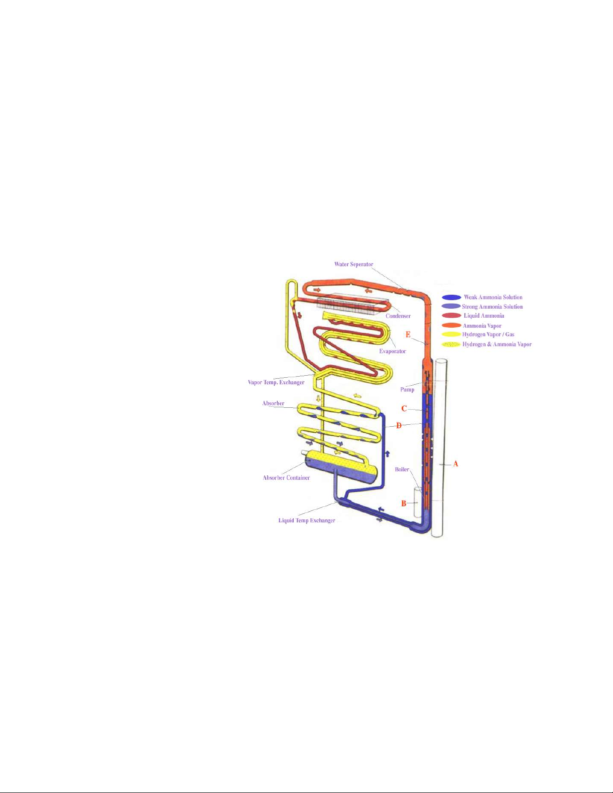
Gemini 105Mc Owner’s Manual
How a Propane Refrigerator Works
How a Propane Refrigerator Works
The continuous absorption type of a cooling unit is operated by the application of a limited amount of heat furnished by gas. No moving parts are employed. The unit
consists of four parts: the boiler, condenser, evaporator
and absorber.
When the unit operates on propane, the heat is supplied
by a burner which is fitted underneath the central tube
(A) .
The unit is charged consisting of a quantity of ammonia,
water and hydrogen at a sufficient pressure to condense
ammonia at the room temperature for which the unit is
designed. When heat is supplied to the boiler system,
bubbles of ammonia gas are produced which
rise and carry with them, quantities of weak
ammonia solution through the siphon pump
- (C). This weak solution passes into the
tube (D), while the ammonia vapor passes
into the vapor pipe (E), and on to the water
separator. Here any water vapor is condensed and runs back to the boiler system,
leaving the dry ammonia vapor to pass to
the condenser. Air circulating over the fins
of the condenser removes heat from the
ammonia vapor to cause it to condense to
liquid ammonia from were it flows into the
evaporator.
Heat is generated in the absorber by the process of absorption. This heat must be dissipated into the surrounding air.
Heat must also be dissipated from the condenser in order to
cool the ammonia vapor sufficiently for it to liquefy. Free air
circulation is therefore necessary over the absorber and
condenser.
The whole unit operates by the heat applied to the boiler
system and it is of paramount importance that this heat is
kept within the necessary limits and is properly applied.
The evaporator is supplied with hydrogen.
The hydrogen passes across the surface of
the ammonia and lowers the ammonia vapor
pressure sufficiently to allow the liquid
ammonia to evaporate. The evaporation of
the ammonia extracts heat from the evaporator, which in turn extracts heat from the
food storage space, as described above,
thereby lowering the temperature inside
the refrigerator.
The mixture of ammonia and hydrogen vapor passes from the evaporator to the absorber.
Entering the upper portion of the absorber is a continuous
trickle of weak ammonia solution fed by gravity from the
tube (D). This weak solution, flowing down through the
absorber, comes in contact with the mixed ammonia and
hydrogen gases which readily absorbs the ammonia from
the mixture, leaving the hydrogen free to rise through the
absorber coil and to return to the evaporator. The hydrogen thus circulates continuously between the absorber and
the evaporator.
The strong ammonia solution produced in the absorber
flows down to the absorber vessel and from there to the
boiler system, thus completing the cycle of operation.
The liquid circulation of the unit is purely gravitational.
53 Copyright © 2004 Performance Cruising Inc.
Page 54

Gemini 105Mc Owner’s Manual
Engine Parts List
Westerbeke Model 30BTHREE Diesel Engine Parts List
Alternator 30594
Belt,Sea Water Pump
Belt,STD Alternator 38527 Preheat & Start Switch 33764
Circuit Breaker 24683 Pump,Fresh Water 37015
Dipstick 37072
Filter,Lube Oil 36918 Pump,Rebuild Kit N/A
Filter,Fuel Oil 30200 Pump,Sea Water 33636
Filter,Electric Lift NA
Gasket,Head 36969 Pump,Impeller Kit 34440
Gasket,Oil Pan 36988 Pump,Repair Kit
Gasket Set,Upper 37116 Pump,Seal 33043
Gasket Set,Complete 37117 Pump,Fuel Lift 37828
Glowplug 36961 Remote Lube Oil Filter 40078
Panel,InstrumentCaptain
Panel,InstrumentAdmiral
Pump,Mounting Gasket
Pump,Mounting Gasket
34466
36473
36843
36957
30326
Harness 15 FT. EXT 8
Harness 15 FT. EXT 4
Heat Exchanger 37564 Solenoid,Preheat 24639
Heat Exchanger End
Heat Exchanger GasInjector 37091 Starter Motor 34552
Injection Pump 37103 Starter Solenoid 36218
Injection Hardware Kit 37121
Injector Nozzle 36935 Thermostat 37043
Injector Return Line 37099
Isolators, Front 40621 Valve Cover Gasket 37007
Isolators, Rear 303062 Voltmeter 37605
Manual,Operator 36906
Manual,Partslist 37115
Manual,Technical 37600
Oil Pressure Switch Below
Oil Pressure Meter 37603
Oil Pressure Sender 24132 Zinc 11885
30760 Silencer,Air Intake
36557 Solenoid,Fuel Shut Off
22850 Spare Parts Kit A
22851 Spare Parts Kit B
Tank,Coolant Recovery
Thermostat Mounting 36956
Water Temperature 37601
Water Temperature 35109
Water Temperature 37493
Water Inj. Exhaust
Elbow 45
Water Inj. Exhaust
Elbow 90
A.) Oil Pressure Switch - 34761 to Dec. 1988 - 37323 From Dec. 1988
36342
37118
37119
24977
37402
37401
54 Copyright © 2004 Performance Cruising Inc.
Page 55

Gemini 105Mc Owner’s Manual
Westerbeke Service Centers
To find the closest Westerbeke Authorized Service Center, contact your local Westerbeke distributor.
A.E.R. MARINE SUPPLY CO. Distributor Covers: Arkansas, Colorado, Kansas, Missouri, New Mexico, Oklahoma, Texas.
P.O. Box 349
2301 Nasa Road One
Seabrook, TX 77586
Contact Information:
Main Contact(s): Mr. Richard S. Miller
Phone: (281) 474-3276 Fax: (281) 474-2714
Email: [email protected], [email protected]
COOK ENGINE COMPANY Distributor Covers: Oregon.
530 NE Tomahawk Is. Dr.
Portland, OR 97217
Contact Information:
Main Contact(s): Ms. Nicki Hudson
Phone: (503) 289-8466 Fax: (503) 286-2836
Email: [email protected]
Web: www.cookengine.com
ENGINES 1 Distributor Covers: Delaware, District of Columbia, Georgia, Maryland, North Carolina, South Carolina, Virginia, West Virginia.
3504 Shipwright St.
Portsmouth, VA 23703
Contact Information:
Main Contact(s): Mr. Tim Walters
Phone: (757) 673-7200
Fax: (757) 673-7211
Email: [email protected]
Web: www.engines1.com
HANSEN MARINE ENG. INC. Distributor Covers: Connecticut, Maine, Massachusetts, New Hampshire, New Jersey, New
York (East of 181), Pennsylvania (East of 181), Rhode Island, Vermont.
Tioga Way, P.O. Box 1106
Marblehead Business Park Marblehead, MA 01945
Contact Information:
Main Contact(s): Mr. Bob Hansen, Mr. Fred Knowles
Phone: (781) 631-3282 Fax: (781) 639-1467
Email: [email protected]
Web: www.hansenmarine.com
MARYSVILLE MARINE NORTH Distributor Covers: Illinois, Indiana, Michigan, New York (West of 181), Ohio, Pennsylvania
(West of 181).
1551 Michigan Avenue
Marysville, MI 48040
55 Copyright © 2004 Performance Cruising Inc.
Page 56

Gemini 105Mc Owner’s Manual
Contact Information:
Main Contact(s): Mr. John Dillon
Phone: (810) 364-7653 Fax: (810) 364-4112
Email: [email protected]
Web: www.marysvillemarine.com
MARYSVILLE MARINE SOUTH Distributor Covers: Kentucky, Tennessee.
127 Industrial Drive
White House, TN 37188
Contact Information:
Main Contact(s): Mr. Matt Harvey
Phone: (615) 672-1142 Fax: (615) 672-8084
Email: [email protected]
Web: www.marysvillemarine.com
MARYSVILLE MARINE WEST Distributor Covers: Iowa, Minnesota, Nebraska, North Dakota, South Dakota, Wisconsin.
405 S. Thompson Rd.
Sun Prairie, WI 53590
Contact Information:
Main Contact(s): Mr. Brian Hunter
Phone: (608) 825-3878 Fax: (608) 825-2790
Email: [email protected]
Web: www.marysvillemarine.com
Westerbeke Service Centers
R.B. GROVE INC. Distributor Covers: Florida.
261 SW 6th Street
Miami, FL 33130-2991
Contact Information:
Main Contact(s): Mr. Tom Piper, Mr. Chris Herting
Phone: (305) 854-5420 Fax: (305) 854-0532
Email: [email protected]
Web: www.rbgrove.com
SEA CHEST MARINE Distributor Covers: Alabama, Louisiana, Mississippi.
7385 West Broadway
New Orleans, LA 70124
Contact Information:
Main Contact(s): Mr. Lawrence Sintes
Phone: (504) 288-8431 Fax: (504) 288-1758
Email: [email protected]
TDC EQUIPMENT Distributor Covers: Arizona, California (Southern), Hawaii, Nevada, Utah.
15886 Manufacture Lane
Huntington Beach, CA 92649
Contact Information:
56 Copyright © 2004 Performance Cruising Inc.
Page 57

Gemini 105Mc Owner’s Manual
Main Contact(s): Ms. Cindy Tutt, Mr. Terry Brown
Phone: (714) 373-8099 Fax: (714) 898-1996
Email: [email protected]
Web: www.tdcequipment.com
TRANS PACIFIC DISTRIBUTORS Distributor Covers: California (Northern).
1941 Walters Court
Fairfield, CA 94533
Contact Information:
Main Contact(s): Mr. Henry Bramhall, Mr. Arley Harty, Mr. Jeff Hemmerlin
Phone: (707) 426-6670 Fax: (707) 426-0206
Email: [email protected]
GALLERY MARINE Distributor Covers: Alaska, Idaho, Montana, Washington, Wyoming.
717 NE Northlake Way
Seattle, WA 98105
Contact Information:
Main Contact(s): Ms. Barbara Jordan
Phone: (206) 547-2477 Fax: (206) 547-2180
Email: [email protected]
Westerbeke Service Centers
57 Copyright © 2004 Performance Cruising Inc.
Page 58

Gemini 105Mc Owner’s Manual
Westerbeke Engine 30B Quick Notes
This addendum is intended as a FAQ (Frequently
Asked Questions) resource for new Gemini owner’s.
For complete instructions on maintenance and care
of your new Westerbeke 30B Diesel Engine, please
read the included manual thoroughly.
Breaking in Your Diesel Engine
Although current technology provides the means of
manufacturing engine parts with unimaginable precision, the manufacturer still falls far short of achieving
the near perfect fit that a proper break-in will provide. “Break-in,” for the most part, is the allowance
of the machined cylinder and ring surfaces to conform
to each other’s shape during engine operation. This
conforming or “mating” of ring and cylinder surfaces is
the ultimate goal of a proper break-in. “Mating” these
two specific parts will produce a very tight seal in
each cylinder. A tight seal is very important because it
prevents the escape of unburned fuel and pressurized
gasses into the crankcase, while further preventing
crankcase oil from entering the cylinder above the top
compression ring.
1. Start engine and run at fast idle, approximately
1500 RPM, and check the oil pressure. Run the engine
for 30 minutes even though coolant may rise to operating temperature in a few minutes. If the coolant
should "boil over," stop engine and allow to cool. Then
start again and proceed as above.
2. Start engine again and make a test run, on the water at 1500 to 2000 rpm’s, and rapidly accelerate to
3500 and decelerate to 1500 rpm's 10 times. Applying
loads to the engine for short periods of time causes
increased ring pressure against the cylinder walls and
helps to seat the rings. This is especially important
because you are "breaking-in" the engine with heavyduty oils. The rapid deceleration increases vacuum and
gives extra lubrication to the piston and ring assemblies.
3. When you have accumulated 25 to 50 hours of operation, change the engine oil and filter according to
manufacturer’s recommendations for oil type and filter number.
4. When required as per your manual, re-torque cylinder heads and manifolds to engine manufacturer's
specifications in proper sequence. Readjust tappets if
necessary. This job is typically performed by a qualified mechanic.
Westerbeke Spare Parts Kit
Performance Cruising does resell the Westerbeke
Spare Parts Kit - (A) - please make checks payable to
Performance Cruising for a total of $170.00 The kit
includes:
• Kit A Zinc (2)
• Heat Exchanger Gasket
• Fuel Elements (2)
• Oil Filter
• Belt
• Fuel Hardware Kit
• Impeller and Gasket Kit
Changing The Oil
Westerbeke recommends replacing the oil filter (Part
36918) with only the Westerbeke supplied oil filter.
There is little price difference between the Westerbeke filter and off-the-shelf filters, but a major difference in the quality of the filter. For your engine’s
sake, use only the Westerbeke filter.
As for oil, the best choice is a heavy duty SAE 30 single
grade oil for our all around operating conditions in the
mid-Atlantic region. . The oil should be changed after
the initial 50 hour break-in period and every 100 hours
of operation or once a season which ever comes
first. Synthetics oils are acceptable, but should not be
used during the break-in period. Check your manual
for exact instruction on how to replace the oil.
Transmission Fluid
The Westerbeke transmission is filled with the same
SAE 30 single grade oil as used in the engine. There is
approximately 1 quart.
Fuel Filters
Your Westerbeke 30B comes installed with one external fuel filter and an additional internal fuel filter.
Westerbeke recommends changing the filters annually
except if you have contaminated fuel, in which case
you will need several filters. The external filter is a
Racor Model 120AS. We recommend using a 30 micron
filter for replacement—part #R12P. Additional replacement filters are part #R12S (2 micron) or R12T (10
micron).
CAUTION: IN THE EVENT OF ENGINE TROUBLE:
If you encounter engine trouble and cannot start the
engine, do not continue attempting to crank the engine without taking a precaution. Prolonged cranking
58 Copyright © 2004 Performance Cruising Inc.
Page 59

Gemini 105Mc Owner’s Manual
Westerbeke Engine 30B Quick Notes
intervals without the engine starting can result in filling the engine mounted exhaust system with sea water
coolant. This may happen because the sea water pump
is pumping sea water through the cooling system during cranking. With prolonged cranking of the engine,
the sea water can enter the engine cylinders by way of
the exhaust manifold once the exhaust system fills.
To prevent this from happening, close the sea cock
valve supplying sea water while attempting to crank
the engine. Once you have corrected the problem and
the engine starts, stop the engine and open the sea
water seacock to allow the flow of sea water to the
engine.
Scheduled Maintenance
Daily (Before Use) Check
1. Oil sump level
2. Coolant level
3. Fuel supply
4. Primary fuel filter/water separator
5. Panel gauges operation (indicating lights, alarms)
6. Transmission fluid level
7. Loose belts, clamps, fittings, wires
Monthly
1. Check zinc anode in heat exchanger
After 50 Hours Initial Operation
1. Change engine lube oil & filter
2. Replace fuel filter elements
3. Torque cylinder head bolts **
4. Adjust valve clearances **
5. Adjust drive belts
6. Check electrical connections
7. Lubricate control cables
8. Change transmission fluid
9. Check idle speed **
After Every 100 Hours
1. Change engine lube oil & filter
2. Adjust drive belts
3. After Every 250 Hours
4. Replace engine fuel filter(s)
5. Check siphon break operation (if installed)
After Every 500 Hours
1. Torque cylinder head bolts **
2. Adjust valve clearances **
3. Drain, flush, refill fresh water coolant
4. Check starter motor drive, lubricate pinion **
5. Check glow plugs
6. Check water injected exhaust elbow condition **
7. Check raw water pump impeller & connections
8. Check Hurth transmission cooler
After Every 800 Hours
1. Remove and check fuel injectors **
2. Check compression pressure **
After Every 1,000 Hours
1. Remove & clean heat exchanger
2. Remove & clean hydraulic transmission cooler
** Should be done by competent mechanic. Refer to
Operator's Manual.
59 Copyright © 2004 Performance Cruising Inc.
Page 60

Gemini 105Mc Owner’s Manual
Bottom Paint FAQ
FAQ Courtesy of BoatingMadeSimple.com
Fading
Antifouling paints are not meant to be cosmetic or decorative coatings and while every effort is made to make them
as aesthetically pleasing as possible. The copper compound
within the antifouling is difficult to mask with color pigments.
All antifouling paints change when they are immersed. So
don't be surprised when you have finished and the color is
not what you had hoped from the color chart, The true color
will establish itself after the boat has been launched. Copolymer and ablative type coatings tend to fade more than
hard antifouling paints.
Along the waterline you will often the antifouling looks dirty
or faded, and can even turn green. This is due to the reaction of the paint with oxygen forming green copper oxide.
Also paints with a higher copper content will turn greener at
the waterline than paints with a lower copper content. For
these reasons you should try keep the paint as close to the
true waterline as possible. Fading is more noticeable in of
ablative coatings than in hard coatings.
How Often Should I Paint My Boat?
That depends on the type of antifouling that is used. The
longevity of multi-season copolymers such as Micron Extra &
Micron CSC is related to the amount of paint applied. These
paints will retain the antifouling properties as long as the
paint is on the hull. Hard antifouling paints work by leaching
biocide out of the paint film and leaving the paint film behind. When this paint film is left out of the water it oxidizes
and any biocide that is left in the coating will not leach out
at the proper rate to control fouling.
sanding the bottom in the spring you will get more coats to
adhere and forestall the day when you must remove all the
antifouling paint from the surface. Soft rosin based antifoulings must always be sanded even if they have just been powerwashed.
Keep in mind that the hulls require only a light handsanding and not
What Is The Difference Between Hard & Soft Paints?
Antifouling type is dictated by the quality, combination,
quantity and type of resin.
Copolymer and Ablative Antifoulings
These types of antifoulings are partially soluble which means
that as water passes across the surface of the coating, the
coating wears down much like a bar of soap would wear
away The action of the water steadily reduces the thickness
of the paint at a controlled rate, which results in always
having fresh biocide at the surface of the paint throughout
the season. For this reason these types of antifoulings have
the capability to perform in the areas of highest fouling
challenge.
Hard antifoulings leach the biocide out of the paint film and
leave the paint film behind on the hull, which causes a build
up of old, spent coatings, Because copolymer and ablative
types of antifoulings wear away with use. There is no buildup of coatings that will eventually have to be removed from
the surface. The minimal build up reduces the maintenance
and preparation needed when it is time to apply more antifouling. In addition Copolymer types such as Micron Extra
with Biolux and Micron CSC can be hauled and relaunched
without repainting as the longevity these coatings are related to the thickness of the paint.
a power sanding.
Must I Sand the Bottom Before Repainting with the Same
Antifouling Especially Since It Was Powerwashed in the
Fall?
Antifouling paint is not meant to be exposed to the elements
and when it sits out of the water for a couple of months the
outside layer of paint film becomes oxidized, and gets soft,
plus it picks up dirt and dust. New paint does not adhere
well to this type of surface and may begin to peel off. Most
non-copolymer paints have a porous "leach layer" and if they
are painted over, after just a power washing the pigment
and the resin penetrate into that porosity and leave a
"blush" of cuprous oxide on the surface. This is a cosmetic
problem and does not really affect the antifouling quality of
the paint but most people if they buy blue paint they want it
to look blue not purple. High-pressure fresh water washing
(3000 psi) will remove the leach layer but the paint will
need to be over-coated immediately after it dries. The other
reason for sanding antifouling paint is that there is only so
much paint that will hold onto a given surface. That amount
may be 10 coats or the first coat may delaminate. This is the
related to how good the original surface preparation was
and how it is maintained between recoating. Sanding when
recoating will add to the longevity of the bottom jobs. By
Ablative types such as Fiberglass Bottomkote Act do not
retain their antifouling ability for more than 30 days after
being hauled out.
Hard Antifoulings
The technical term for these types of antifouling paints is
"contact leaching". The paint dries to a porous film that is
packed with Biocides, which leach out on contact with water
to prevent fouling growth. This leaching is chemically design
to release biocide throughout the season, but the amount
will steadily decrease until there is not enough biocide coming out of the paint film to maintain fouling protection.
Once the biocide is exhausted, the hard paint film remains
on the boat. One of the main benefits of this type of antifouling is its resistance to abrasion and rubbing. This makes
it ideal for fast powerboats, racing sailboats or boats where
the owners have the bottoms cleaned regularly.
Most hard antifouling paints can be wet sanded and burnished prior launch to reduce drag and improve hull speed.
A disadvantage to hard antifouling paint is the buildup of
residual paint film that occurs when the surface is not prop-
60 Copyright © 2004 Performance Cruising Inc.
Page 61

Gemini 105Mc Owner’s Manual
Bottom Paint FAQ
erly sanded prior to application of new coats of antifouling.
When hard paints are hauled and stored for the winter season, the paint film, as well as the biocide oxidizes and this
makes it more difficult to release more biocide out of the
film. For this reason, they must be sanded and recoated
with fresh antifoulinq before relaunching.
Teflon Antifoulings
Most people associate Teflon with nonstick household products or with the space program, but the properties that
made it perfect for those applications also make it an ideal
ingredient in antifouling paint. Teflon creates the lowest
coefficient of drag in any coating available. The lower the
friction, the less energy is required to move the boat
through the water. For powerboats this means greater
RPM's, increasing speed and fuel savings. For sailboats,
greater speeds are achieved with less wind.
Soft Antifoulings
Soft or sloughing antifoulings provides dependable low cost
protection for cruising boats or boats with displacement or
non-planing hulls. These paints are easy to clean and remove
at haul out which prevents paint build-up. These types of
coatings must be launched within 48 hours of painting to
retain maximum effect effectiveness.
Is More Copper Better In Bottom Paints?
The level of copper is not the only determining factor of
how an antifouling paint will perform.
The resin-binder system, the material that holds the paint
together, is equally important. Not only does the resinbinder system hold the paint together, it is the mechanism
that determines how fast the copper and other biocide will
be released. The resin-binder system must be carefully tailored for the amount and type of copper and other biocides
used to obtain maximum efficiency The amount of copper or
other biocide may effect the life of an antifouling paint but
the sophistication of the resin-binder system to hold and
release copper or other biocide at the proper rate is far
more important to the effectiveness of the antifouling. A
copolymer or ablative antifouling will release biocide at
nearly constant rate throughout its life. For this reason,
highly efficient antifouling paints like Micron, are less dependent on large amounts of copper and other Biocides and
deliver the best possible performance.
The presence of boosting biocides, such as Biolux, by keeping the bottom clear of slime will make the copper more
effective.
Why Should I Bother Painting My Boat?
Once fouling has established a hold on a boat hull it will
rapidly spread or "colonize" the surface. Prevention is therefore better than the cure of having to remove the fouling by
scraping.
There are a number of key reasons to keep your hull free
from fouling:
Safety - Heavy fouling growth reduces responsiveness of the
craft. The added weight of the fouling can make the boat sit
lower in the water than intended. This can have obvious
implications in heavy weather conditions.
Protection - Prolonged growth of certain types of fouling can
damage the substrate of the hull. For example, the natural
glues used to attach organisms to the hull can damage wood
and fiberglass. Fouling can also clog water intakes and cause
damage to the engines.
Speed and efficiency - Fouling causes drag. As drag is increased, fuel consumption increases and speed is reduced
even to the point where a planing hull may not be able to
get on plane. For racing boats, this can be the difference
between winning and losing a race.
What's This I Hear About Pettit's Irgarol & Interlux's Biolux
Anti Slime Additives?
Trinidad SR Slime-Resistant Antifouling Paint
How do you make the best better? By adding new techno-
logical developments to your number one antifouling paint.
Trinidad SR has the same basic hard-to-improve-on formula
as our regular Trinidad but with the addition of a booster
additive called Irgarol, that significantly reduces soft growth
and slime (SR stands for Slime Resistant). Irgarol was developed by the Ciba Additive Group has gone through years of
extensive testing under the auspices of the EPA. Trinidad SR
meets all VOC (Volatile Organic Compounds) regulations.
Trinidad SR high copper load (contains 70.0% cuprous oxide),
will give excellent service even in most heavily infested
waters. Trinidad SR is easy to apply by brush, roller or spray
and has excellent adhesion to fiberglass, wood and steel
hulls.
Trinidad SR is available in four colors.
What is Biolux?
Biolux is a unique antifouling technology developed by Interlux incorporating organic boosting biocides into a special
biocide release system. This blocks slime growth for a fouling free boat bottom.
How does it work?
Just like ordinary plants, Slime and Algae feed on sunlight.
Formulations that use Biolux technology prevent algae and
slime from being able to grow by acting like sunscreen to
block this process.
Soon after the boat is launched it comes in contact with
algae in the water. Once these materials attach and feed,
they begin to secrete a gel like substance that attracts more
algae until it begins to look like a carpet on the bottom of
your boat. This increases drag, increases fuel consumption
and makes the boat more difficult to handle, which can be a
problem in heavy weather. If left on the surface, it restricts
the copper being released to the surface to prevent shell
fouling.
61 Copyright © 2004 Performance Cruising Inc.
Page 62

Gemini 105Mc Owner’s Manual
Assorted Paint And Environmental Questions Below
How many coats of antifouling paint do I need for complete
protection?
For complete protection throughout the boating season,
two full coats of antifouling paint are recommended. For
multi-seasonal protection with ablative antifoulings, three
or more coats are recommended, with an extra coat on
high wear areas such as the waterline and leading edges.
Since each coat of paint is only around two thousandths of
an inch thick, it is vitally important to apply the correct
number of coats.
Sometimes I hear stories of freshly painted hulls fouling.
Why does this happen?
Antifouling paints in general, perform admirably even when
faced with overwhelming fouling pressure. Early fouling is
often attributed to silt or slime clogging the pores of the
antifouling paint reducing its efficacy. This is why it is important to maximize the service life of the antifouling paint
by lightly scrubbing periodically to remove slime or dirt
accumulations.
How long will the antifouling paint last?
This depends on several factors, not the least of which are
the choice of paint and location of the boat. Two coats of a
weaker paint applied to a boat in a high fouling area will
most likely not prevent fouling for the entire season. It is
important to match the paint with the boat location. When
the proper paint is chosen, two coats should last the entire
boating season. safety and safe procedures while harvesting geoducks.
Bottom Paint FAQ
62 Copyright © 2004 Performance Cruising Inc.
 Loading...