


301008301008
INSTALLATION MANUAL
PERFORMANCE EXHAUST

EGR & Cooler Delete for
EGR & Cooler Delete for
2010-2012 6.7L Cummins
2010-2012 6.7L Cummins
WARNING
ONLY install this kit if you are using a tuner
that disables the EGR sensors & circuit system.
Any product that requires the removal of ANY
emissions control device is strictly prohibited
and is intended for closed course racing only
for non-registered vehicles.
EGR Delete Will:
Allow removal of the EGR assembly
EGT solution for monitoring temperatures
Clean up the engine bay
Re-route coolant with provided hose

A
Your Kit Includes
H
B
G
C
D
F
A (1) Support Bracket
B (2) Exhaust Block-Off Plates
C (1) Coolant Hose
D (1) Coolant Hose Connector
E (1) Stand Off Bolt
F (1) M10 Flanged Nut
G (1) Intake Block-Off Plate
H (1) Hardware Bag Containing:
----------(2) 5/16 Bolts, Nuts & Flat Washers
----------(1) 1/4-20 Bolt, Nut & Lock Washer
----------(2) M10 Hex Head Bolts
----------(4) M8 by 1.25 by 20 Allen Head Bolts
E

Preparation
STEP 1: Un-hook negative battery terminals & drain
engine coolant.
STEP 2: Remove the plastic engine cover by removing
the four 8mm bolts as well as the dipstick.
STEP 3: Loosen the two V-Band clamps and remove
the 10mm bolt in the center of the tube. Then
disconnect the sensor plug and remove the
EGR crossover tube. (Fig. 1)
EGR Valve
Fig. 1
STEP 4: Remove the electrical connector on the EGR
valve (Circled in Fig. 2) then remove the EGR
valve itself which is held in place with four
10mm bolts.
Fig. 2
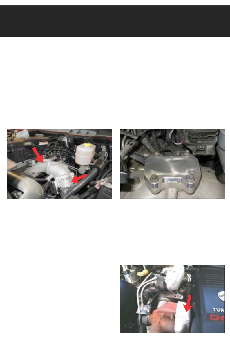
Blocking the Intake
STEP 5: Ensure the mounting surface on the intake
elbow is clear of any gasket material.
STEP 6: Unplug the electrical connector from the
backside of the throttle valve. The throttle
valve is shown in Fig. 3.
Intake Elbow
Throttle Valve
Fig. 3
STEP 7: Install the intake block-off (G) with supplied
bolts. (Fig. 4) Ensure both O-Rings are fully
seated.
STEP 8: Remove heat shield from EGR bypass. This is
held in place by three 10mm nuts and two
8mm bolts. (Fig. 5)
Fig. 4
Fig. 5

Removing Bypass/Servo
STEP 9: Now that you've removed the heat shield,
remove the four 10mm bolts holding the
exhaust bypass in place. The bypass will be
removed with the servo in the next steps.
Servo
Bypass
Coolant Lines
Fig. 6
STEP 10: Remove the five 10mm bolts securing the
EGR servo mounting bracket in place.
Simultaneously remove the EGR servo & the
exhaust bypass from the vehicle. (Fig. 6)
Fig. 7
STEP 11: Remove the crankcase breather tube that
runs over the EGR cooler. Also, disconnect
the two coolant lines that run to the EGR
cooler. Be sure to remove the O-Ring fitting
from the engine block. (Fig. 7) Remove the
four 10mm EGR cooler mounting bolts
(Circled Fig. 7).
STEP 12: Remove the two 15mm nuts connecting to the
EGR cooler to the exhaust manifold near the
fire wall.

Removing EGR Cooler
STEP 13: Remove the V-Band clamp that is connecting
the EGR cooler and the exhaust crossover
elbow. (Fig. 8)
Exhaust
Crossover
EGR Cooler
Elbow
Fig. 8
STEP 14: Remove the exhaust crossover elbow that is
held in place by two 15mm nuts. Install the
smaller of the two exhaust block off plates.
Location noted in Fig. 9.
STEP 15: Remove the EGR cooler by pulling up and out
towards the front of the vehicle.
STEP 16: Remove the EGR cooler mounting bracket by
unbolting the two 14mm bolts that bolt
directly to the engine. Fig. 10
Fig. 9
Fig. 10

Block EGR & Reassemble
STEP 17: Install the other (ported) exhaust block-off
plate on the back side of the exhaust
manifold. Be sure to reuse the factory
hardware. (Fig. 11)
Fig. 11
STEP 18: Re-install the crankcase breather tube. Using
the new supplied coolant hose (C) and
adapter (D), connect the two coolant ports
that previously went to the EGR cooler and
secure with provided hose clamps.
STEP 19: Replace the manifold bolt with the supplied
stand off bolt (E). The bolt will be the third
bolt in from the back of the motor. The nut (F)
on the stand off bolt should be used as a jam
nut to secure it in place. (Fig. 12)
Fig. 12

Install Bracket & Test
STEP 20: Mount the supplied support bracket as seen
in Fig. 13. The back bolt screws into the
stand off bolt (G). Use the 1/4-20 bolt, nut,
washer to secure the trans dipstick to the
bracket. (Fig. 13)
STEP 21: Refill the coolant
to factory specs.
Fig. 13
STEP 22: Installation is now complete! Start the engine
to circulate coolant. Top off as necessary and
inspect for leaks. Install the plastic engine
cover and you're done!
Bracket Diagram
Dipstick
Mount
Crank Case
Tube Mount
Stand Off
Bolt Mount
Coolant Hose
Adapter Slot
Exhaust Pressure
Tube Mount
Factory Coolant
Tube Mount


PERFORMANCE EXHAUST
www.flopro.com
 Loading...