

Version 1.2
Revision Date: August 21, 2012
www.perfectron.com
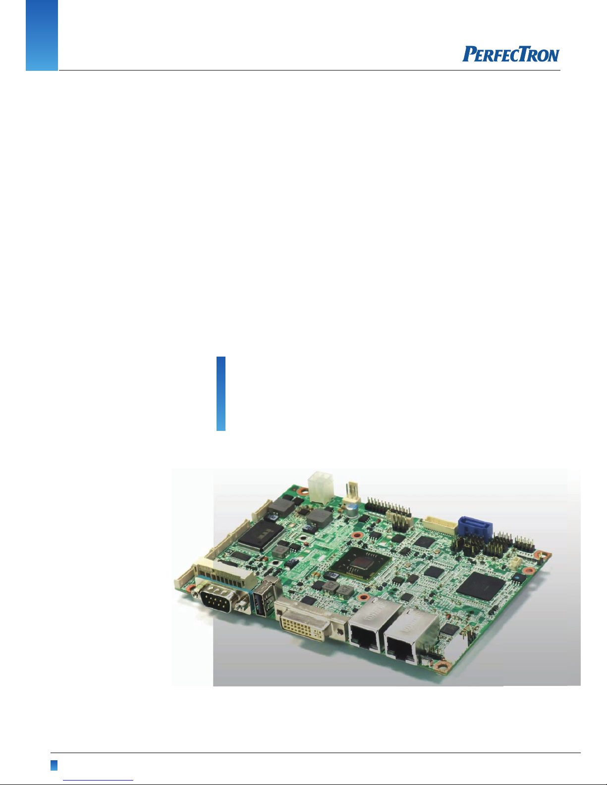
OXY5320A
3.5" Single Board Computer
User’s Manual
User’s Manual

OXY5320A 3.5” SBC User’s Manual V1.2
www.perfectron.com
Safety Information
Electrical safety
To prevent electrical shock hazard, disconnect the power cable from the
electrical outlet before relocating the system.
When adding or removing devices to or from the system, ensure that the power
cables for the devices are unplugged before the signal cables are connected. If
possible, disconnect all power cables from the existing system before you add a
device.
Before connecting or removing signal cables from the motherboard, ensure that
all power cables are unplugged.
Seek professional assistance before using an adapter or extension cord. These
devices could interrupt the grounding circuit.
Make sure that your power supply is set to the correct voltage in your area.
If you are not sure about the voltage of the electrical outlet you are using,
contact your local power company.
If the power supply is broken, do not try to fix it by yourself. Contact a qualified
service technician or your local distributor.
Operation safety
Before installing the motherboard and adding devices on it, carefully read all the
manuals that came with the package.
Before using the product, make sure all cables are correctly connected and the
power cables are not damaged. If you detect any damage, contact your dealer
immediately.
To avoid short circuits, keep paper clips, screws, and staples away from
connectors, slots, sockets and circuitry.
Avoid dust, humidity, and temperature extremes. Do not place the product in any
area where it may become wet.
Place the product on a stable surface.
If you encounter any technical problems with the product, contact your local
distributor
Statement
All rights reserved. No part of this publication may be reproduced in any form or
by any means, without prior written permission from the publisher.
All trademarks are the properties of the respective owners.
All product specifications are subject to change without prior notice
1

OXY5320A 3.5” SBC User’s Manual V1.2
www.perfectron.com
Revision History
Revision Date (dd.mm.yyyy) Changes
Version 1.0 28.05.2012 Initial release
Version 1.1 19.07.2012 Disable COM5
Version 1.2 21.08.2012 Enable COM5
Packing list
□ OXY5320A 3.5” SBC
□ CD (Driver + user's manual)
Optional Accessories
□ Cable kit for OXY5320A
□ Passive heatsink (up to 75°C)
□ CPU cooler
Ordering Information
Model Number Description
OXY5320A-ET 3.5'' SBC Intel® Cedarview N2600 with DDR3 SODIMM, Dual Display
by LVDS/DVI-I, Dual GbE LAN, Audio, 5 x COM, 7 x USB, and 12V DCin (-20 to 70°C)
OXY5320A-UT 3.5'' SBC Intel® Cedarview N2600 with DDR3 SODIMM, Dual Display
by LVDS/DVI-I, Dual GbE LAN, Audio, 5 x COM, 7 x USB, and 12V DCin (-40 to 85°C)
If any of the above items is damaged or missing, please contact your local
distributor.
2

OXY5320A 3.5” SBC User’s Manual V1.2
www.perfectron.com
Table of Contents
SAFETY INFORMATION ............................................................................................................................. 1
ELECTRICAL SAFETY.......................................................................................................................................... 1
OPERATION SAFETY ......................................................................................................................................... 1
STATEMENT ................................................................................................................................................... 1
REVISION HISTORY .......................................................................................................................................... 2
PACKING LIST ................................................................................................................................................. 2
OPTIONAL ACCESSORIES ................................................................................................................................... 2
ORDERING INFORMATION ................................................................................................................................. 2
CHAPTER 1: PRODUCT INFORMATION ...................................................................................................... 5
1.1 BLOCK DIAGRAM ...................................................................................................................................... 5
1.2 SPECIFICATIONS ........................................................................................................................................ 6
1.3 BOARD PLACEMENT .................................................................................................................................. 8
1.4 ONBOARD CONNECTOR LIST ........................................................................................................................ 9
1.5 MECHANICAL DRAWINGS ......................................................................................................................... 10
CHAPTER 2: JUMPERS AND CONNECTORS .............................................................................................. 11
2.1 JUMPER SETTINGS ................................................................................................................................... 11
PSON1: ATX/AT mode Selection ........................................................................................................... 11
2.2 CONNECTOR PIN DEFINITIONS ................................................................................................................... 11
ATX1: Power input connector .............................................................................................................. 11
FAN: 3 pin FAN connector .................................................................................................................... 11
LPT1: LPT port pin header ................................................................................................................... 12
LVDS_CON: LVDS Connector ................................................................................................................ 12
JBKL1: Inverter connector .................................................................................................................... 13
KBMS1: KB/MS Pin Header ................................................................................................................. 13
FP1: Front Panel 1 Pin Header ............................................................................................................. 13
USB1, USB2, USB3: USB2.0 Pin Header ............................................................................................... 13
RUSB1: USB2.0 port 6 connector ......................................................................................................... 14
DIO1: Digital input/output pin header ................................................................................................ 14
AUDIO1: LINE-OUT/LINE-IN/MIC-IN .................................................................................................... 14
SPDIF1: SPDIF OUT pin header ............................................................................................................ 14
AMP1: AMP output pin header ........................................................................................................... 14
LAN1, LAN2: LAN connector ................................................................................................................ 15
DVI: DVI-I connector ............................................................................................................................ 15
COM1: RS232/422/485 with +12V/+5V selection................................................................................. 16
COM2, COM3, COM4: RS232 with +12V/+5V selection (1x10 pin Wafer) ........................................... 16
COM5: RS232 ...................................................................................................................................... 16
MPCIE1: Mini PCIE connector .............................................................................................................. 17
DEBUG: Debug card connector ............................................................................................................ 17
BAT1: RTC battery connector ............................................................................................................... 17
CFAST: CFAST connector ...................................................................................................................... 18
SATA1: Serial ATA 2.0 Connector .......................................................................................................... 18
CHAPTER 3: GETTING STARTED............................................................................................................... 19
3.1 INSTALLING SYSTEM MEMORY ................................................................................................................... 19
3.2 INSTALLING THE CFAST CARD ..................................................................................................................... 19
CHAPTER 4: AMI BIOS UTILITY................................................................................................................ 20
4.1 STARTING .............................................................................................................................................. 20
4.2 NAVIGATION KEYS ................................................................................................................................... 20
4.3 MAIN MENU ......................................................................................................................................... 21
4.4 ADVANCED MENU ................................................................................................................................... 21
4.4.1 PCI Subsystem Settings ............................................................................................................... 22
3

OXY5320A 3.5” SBC User’s Manual V1.2
www.perfectron.com
4.4.2 ACPI Settings .............................................................................................................................. 22
4.4.3 Trusted Computing ..................................................................................................................... 23
4.4.4 CPU Configuration ...................................................................................................................... 23
4.4.5 Thermal Configuration ............................................................................................................... 24
4.4.6 IDE Configuration ....................................................................................................................... 25
4.4.7 Intel Fast Flash Standby.............................................................................................................. 25
4.4.8 USB Configuration ...................................................................................................................... 26
4.4.9 SMART Settings ...........................................................................................................................27
4.4.10 Super IO Configuration ..............................................................................................................27
4.4.11 Smart Fan Function .................................................................................................................. 28
4.4.12 H/W Monitor ............................................................................................................................ 28
4.4.13 AOAC Configuration ................................................................................................................. 29
4.4.14 Demo Board ............................................................................................................................. 29
4.4.15 Serial Port Console Redirection ................................................................................................ 29
4.4.16 PPM Configuration ................................................................................................................... 30
4.5 CHIPSET ................................................................................................................................................ 30
4.6 BOOT SETTING ....................................................................................................................................... 32
4.7 SECURITY ............................................................................................................................................... 33
4.8 SAVE AND EXIT ........................................................................................................................................ 34
4
OXY5320A 3.5” SBC User’s Manual V1.2
www.perfectron.com
Chapter 1: Product Information
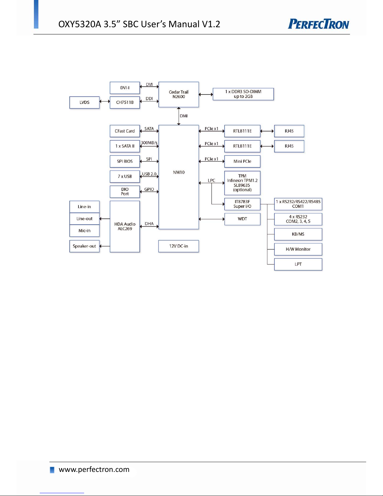
1.1 Block Diagram
5
OXY5320A 3.5” SBC User’s Manual V1.2
www.perfectron.com
1.2 Specifications
Processor & System
CPU Type
Intel® Atom™ N2600 1.60GHz onboard
Chipset
Intel® NM10
Memory Type
1 x 204 pin SO-DIMM DDR3 800/1066 up to 2GB
BIOS
AMI® BIOS
Super I/O
ITE IT8783F
TPM
Infineon TPM1.2 SLB9635 (optional)
Expansion Slot
1 x Mini PCIe Slot
Display
Chipset
Integrated Intel® GMA3600 VR Graphic core SGX545
DVI-I
Yes (Max. resolution 1920 x 1200 @60Hz)
LVDS
Supports 18/24‐bit single/dual channel LVDS
(Max. resolution 1600 x 1200 @60Hz)
Dual Independent
Displays Capability
LVDS + DVI-I
Audio
Codec
Realtek ALC269 High Definition Audio Codec
*2W amplifier onboard
Ethernet
Chipset
2 x RTL8111E GbE LAN
WOL
Yes
Boot from LAN
Yes for PXE
Rear I/O
DVI-I
1 (DVI-D + VGA)
Ethernet
2 x RJ45
USB 1.1/2.0
1
COM
1 x RS-232/422/485 with 5V/12V selection
Reset Button
1
Internal I/O
SATA
1 x SATAII (3Gb/s)
SSD
1 x CFast Socket
USB 2.0
6 x USB2.0 ports by 2 x 5-pin header
COM
4 x COM ports
COM2~COM5 ports support RS232 only with
5V/12V selectable by 1 x 10-pin header
Audio
1 x 4-pin header for Speak-out
LVDS
30 pin connector
PS/2
2 x 4 pin header
LPT
2 x 13 pin header
DIO
8-bit (4 in/4 out)
6

OXY5320A 3.5” SBC User’s Manual V1.2
www.perfectron.com
Mechanical and Environment
Form Factor
3.5" SBC
Power Type
12V DC-in, 4-pin ATX power connector, AT/ATX
mode support
Dimension
146mm x 102mm (5.7" x 4")
Operating Temp.
-20 to 70°C
Storage Temp.
-20 to 85°C
Relative Humidity
10% to 90%, non-condensing
* All specifications and photos are subject to change without notice*
7
OXY5320A 3.5” SBC User’s Manual V1.2
www.perfectron.com
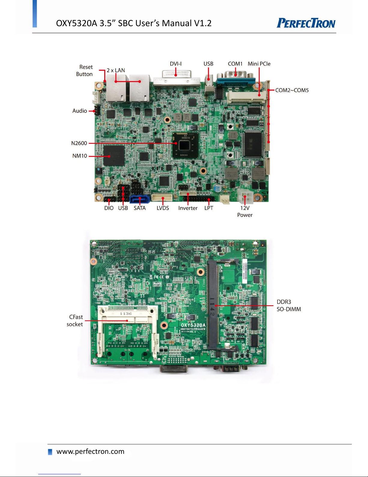
1.3 Board Placement
8

OXY5320A 3.5” SBC User’s Manual V1.2
www.perfectron.com
1.4 Onboard Connector List
Label
Function
ATX1
Power input connector
FAN1
3 pin FAN connector
LPT1
LPT port pin header
CLRCMOS1
Clear CMOS jumper setting
PSON1
ATX/AT MODE setting
LVDS_CON
LVDS connector
JBKL1
Inverter connector
KBMS1
PS2 KB/MS
FP1
Front panel 1
FP2
Front panel 2
USB1
USB2.0 port 0,1 pin header
USB2
USB2.0 port 2,3 pin header
USB3
USB2.0 port 4,5 pin header
RUSB1
USB2.0 port 6 connector
DIO1
Digital input/output pin header
AUDIO1
LINE-OUT/LINE-IN/MIC-IN
SPDIF1
SPDIF OUT
AMP1
AMP output pin header
LAN1
LAN connector 1
LAN2
LAN connector 2
DVI
DVI-I
COM1
RS232/422/485 with +12V/+5V selection
COM2
RS232 with +12V/+5V selection
COM3
RS232 with +12V/+5V selection
COM4
RS232 with +12V/+5V selection
COM5
RS232
MPCIE1
Mini PCIE connector
DEBUG
Debug card connector
BAT1
RTC battery connector
CFAST
CFAST connector
DDR3_1
DDR3 SO-DIMM connector
SATA1
Serial ATA 2.0 Connector
9

OXY5320A 3.5” SBC User’s Manual V1.2
www.perfectron.com
1.5 Mechanical Drawings
10

OXY5320A 3.5” SBC User’s Manual V1.2
www.perfectron.com
Chapter 2: Jumpers and Connectors
2.1 Jumper Settings
PSON1: ATX/AT mode Selection
Jumper
Function description
Setting
1-2
AT Mode
2-3
ATX Mode
*Default setting is 2-3*
2.2 Connector Pin Definitions
ATX1: Power input connector
Pin
Definition
1
GND
2
GND
3
+12V
4
+12V
FAN: 3 pin FAN connector
Pin
Definition
1
GND
2
+12V
3
FANIN_CPU
11

OXY5320A 3.5” SBC User’s Manual V1.2
www.perfectron.com
LPT1: LPT port pin header
Pin
Definition
Pin
Definition
1
STB#
2
AFD#
3
SPD0
4
ERROR#
5
SPD1
6
PINIT#
7
SPD2
8
SLIN#
9
SPD3
10
GND
11
SPD4
12
GND
13
SPD5
14
GND
15
SPD6
16
GND
17
SPD7
18
GND
19
ACK#
20
GND
21
BUSY
22
GND
23
PE
24
GND
25
SLCT
26
NC
LVDS_CON: LVDS Connector
Pin
Definition
Pin
Definition
1
LVDS_BCLK
2
GND
3
LVDS_BCLK#
4
LVDS_A3
5
GND
6
LVDS_A3#
7
LVDS_B3
8
GND
9
LVDS_B3#
10
LVDS_ACLK
11
LVDS_B2
12
LVDS_ ACLK #
13
LVDS_B2#
14
GND
15
LVDS_B1
16
LVDS_A2
17
LVDS_B1#
18
LVDS_A2#
19
LVDS_B0
20
LVDS_A1
21
LVDS_B0#
22
LVDS_A1#
23
GND
24
LVDS_A0
25
LVDS_DCC_SC
26
LVDS_A0#
27
LVDS_DCC_SD
28
GND
29
LVDS_VDD
30
LVDS_VDD
12

OXY5320A 3.5” SBC User’s Manual V1.2
www.perfectron.com
JBKL1: Inverter connector
Pin
Definition
1
VCC12_LVDSP
2
VCC12_LVDSP
3
VCC12_LVDSP
4
VCC_LVDSP
5
VCC_LVDSP
6
GND
7
GND
8
BL_EN
9
BL_ADJ
10
GND
KBMS1: KB/MS Pin Header
Pin
Definition
Pin
Definition
1
+5VSB
2
GND
3
NC 4 GND
5
MSDAT_SIO
6
KBDAT_SIO
7
MSCLK_SIO
8
KBCLK_SIO
FP1: Front Panel 1 Pin Header
Pin
Definition
Pin
Definition
1
HDLED+
2
PLED+
3
HDD_ACT_
4
PLED-
5
GND
6
PWRBTN_
7
SYSRST_
8
GND
9
DUMMY
10
NC
USB1, USB2, USB3: USB2.0 Pin Header
Pin
Definition
Pin
Definition
1
FUSEVCC
2
FUSEVCC
3
USBN
4
USBN
5
USBP
6
USBP
7
GND
8
GND
9
NC
10
GND
13

OXY5320A 3.5” SBC User’s Manual V1.2
www.perfectron.com
RUSB1: USB2.0 port 6 connector
Pin
Definition
1
+5V
2
USBN
3
USBP
4
GND
DIO1: Digital input/output pin header
Pin
Definition
Pin
Definition
1
SBDO0
2
SBDI0
3
SBDO1
4
SBDI1
5
SBDO2
6
SBDI2
7
SBDO3
8
SBDI3
9
+5VIO
10
GND
AUDIO1: LINE-OUT/LINE-IN/MIC-IN
Pin
Definition
Pin
Definition
1
L_IN_L
2
L_IN_R
3
NC 4 AGND
5
MIC_IN
6
AGND
7
L_OUT_R
8
L_OUT_L
SPDIF1: SPDIF OUT pin header
Pin
Definition
1
+5V
2
SPDIF_OUT
3
GND
AMP1: AMP output pin header
Pin
Definition
1
SP_OUT_R-
2
SP_OUT_R+
3
SP_OUT_L+
4
SP_OUT_L-
14
OXY5320A 3.5” SBC User’s Manual V1.2
www.perfectron.com
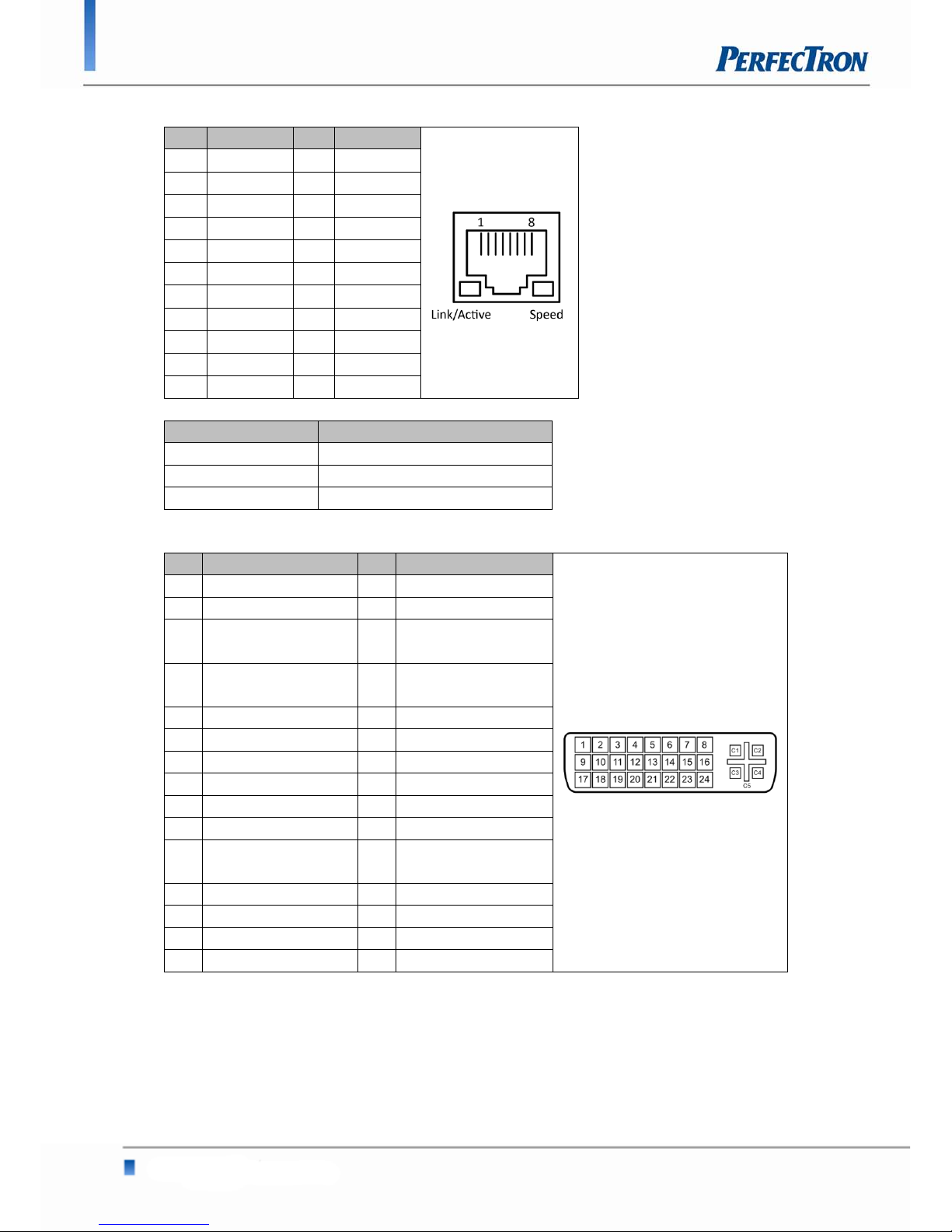
LAN1, LAN2: LAN connector
Pin Definition Pin Definition
R5 VCC R6 VCC
R1 TD1+ L3 YLEDR2 TD1- L4 YLED+
R3 TD2+ L1 GLEDR4 TD2- L2 OLEDR7 TD3+ G3 GND
R8 TD3- G4 GND
R9 TD4+
R10 TD4-
G1 GND
G2 GND
SPEED LED: (Lift) ACTIVE LED: (Right)
GREEN: 1000Mbps ORANGE (BLINKING): ACTIVITY
ORANGE: 100Mbps No Light: NOT LINK
No Light: 10Mbps ORANGE (NO BLINKING): LINK
DVI: DVI-I connector
Pin Definition Pin Definition
1 TMDS Data2- 16 Hot Plug Detect
2 TMDS Data2+ 17 TMDS Data03 TMDS Data2/4
Shield
18 TMDS Data0+
4 TMDS Data4- 19 TMDS Data0/5
Shield
5 TMDS Data4+ 20 TMDS Data56 DDC Clock 21 TMDS Data5+
7 DDC Data 22 TMDS Clock Shield
8 Analog Vert. Sync 23 TMDS Clock+
9 TMDS Data1- 24 TMDS Clock10 TMDS Data1+ C1 Analog Red
11 TMDS Data1/3
Shield
C2 Analog Green
12 TMDS Data3- C3 Analog Blue
13 TMDS Data3+ C4 Analog Horiz. Sync
14 +5V Power C5 Analog GND
15 GND
15
OXY5320A 3.5” SBC User’s Manual V1.2
www.perfectron.com
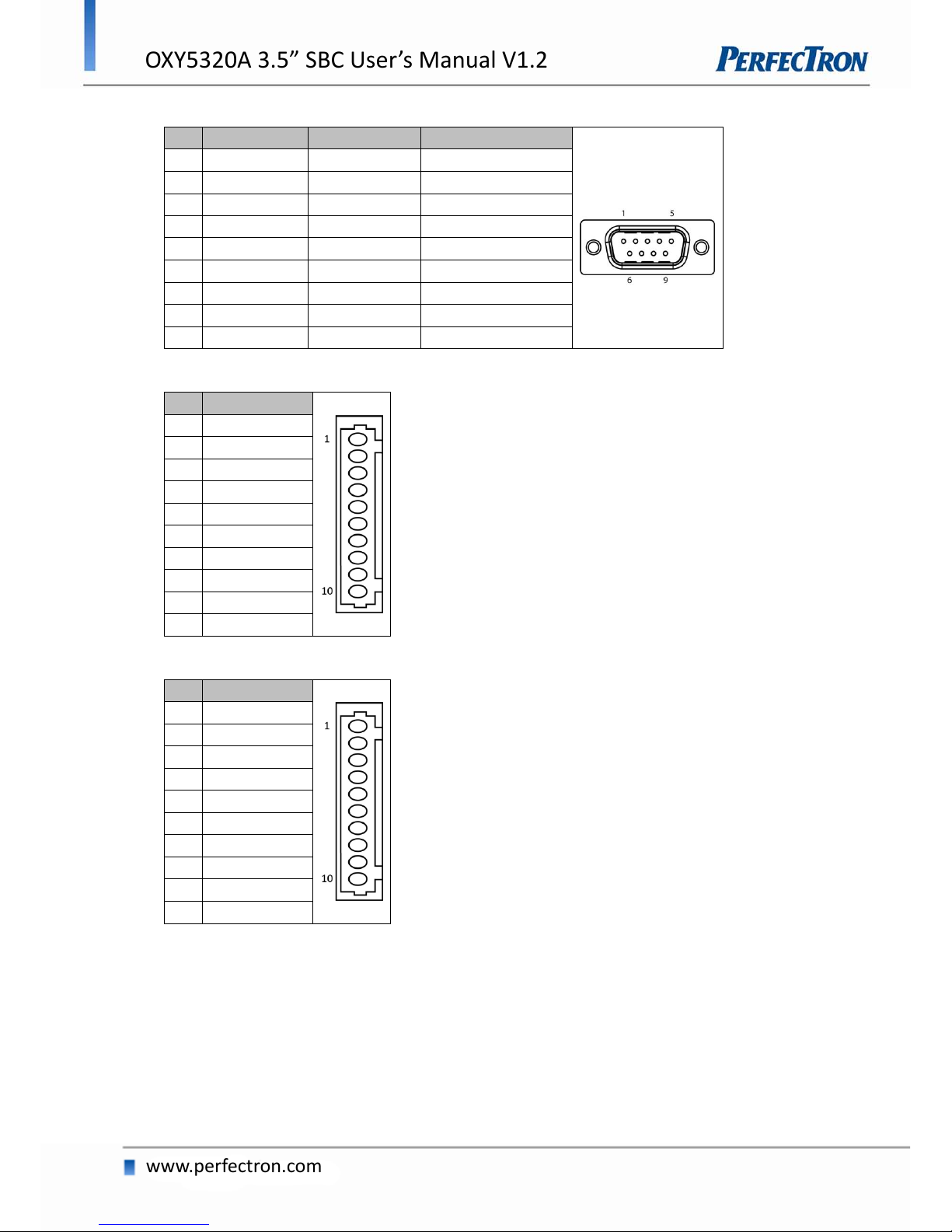
COM1: RS232/422/485 with +12V/+5V selection
Pin
RS-232
RS-422
Half Duplex RS-485
1
DCD
TX-
DATA-
2
RXD
RX+
NA 3 TXD
TX+
DATA+
4
DTR
RX-
NA 5 GND
GND
GND
6
DSR
NA
NA 7 RTS
NA
NA
8
CTS
NA
NA
9
+5V/+12V/RI
+5V/+12V/NA
+5V/+12V/NA
COM2, COM3, COM4: RS232 with +12V/+5V selection (1x10 pin Wafer)
Pin
Definition
1
+CM_P1 DCD
2
CM_DSR
3
CM_RXD
4
CM_RTS
5
CM_TXD
6
CM_CTS
7
CM_DTR
8
+CM2_P9 RI
9
GND
10
+5VIO
COM5: RS232
Pin
Definition
1
+CM_P1 DCD
2
CM_DSR
3
CM_RXD
4
CM_RTS
5
CM_TXD
6
CM_CTS
7
CM_DTR
8
+CM_P9 RI
9
GND
10
+5VIO
16
OXY5320A 3.5” SBC User’s Manual V1.2
www.perfectron.com
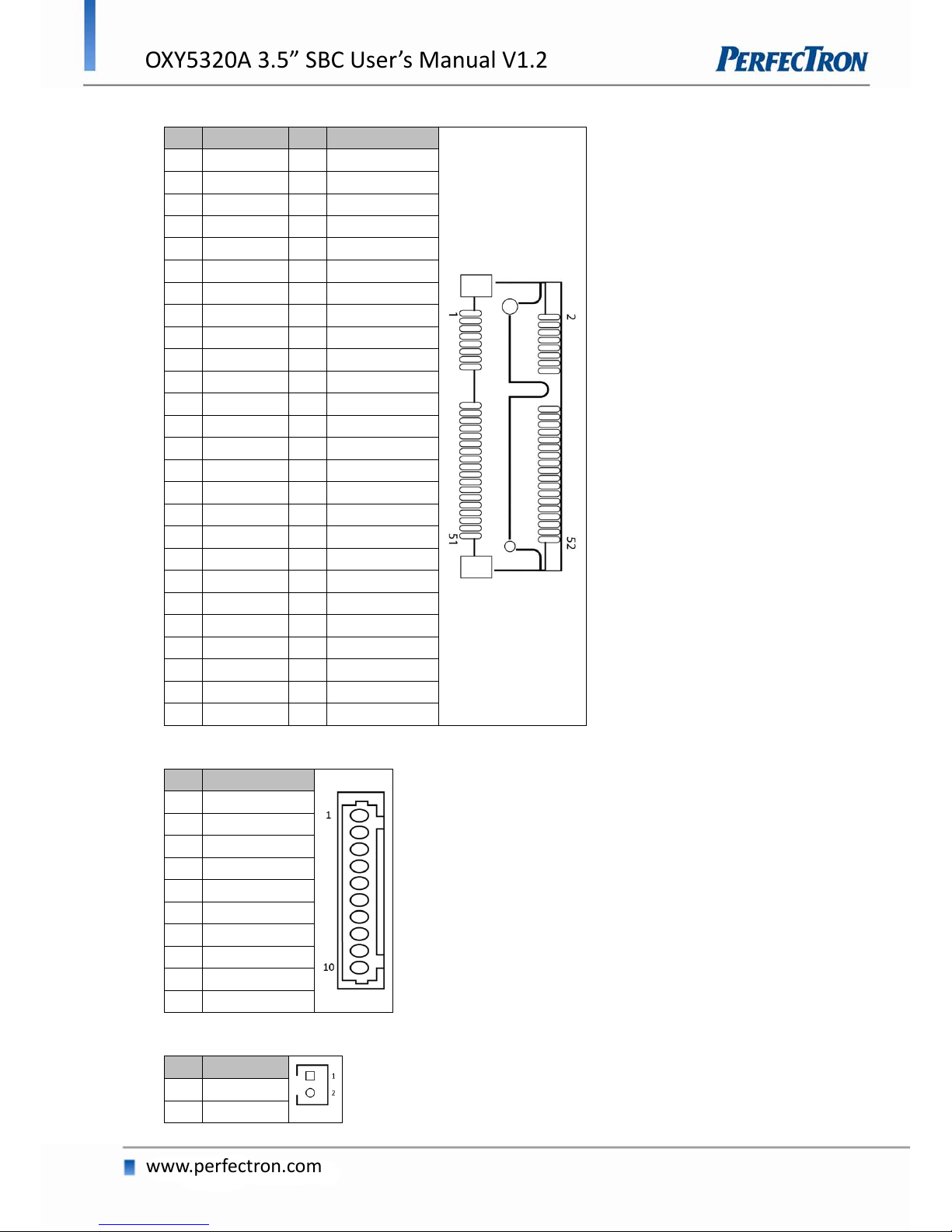
MPCIE1: Mini PCIE connector
Pin
Definition
Pin
Definition
1
WAKE#
2
+3.3V
3
Reserved
4
GND
5
Reserved
6
+1.5V
7
CLKREQ#
8
Reserved
9
GND
10
Reserved
11
REF CLK-
12
Reserved
13
REF CLK+
14
Reserved
15
GND
16
Reserved
17
Reserved
18
GND
19
Reserved
20
Reserved
21
GND
22
PERST#
23
PERN0
24
+3.3VAUX
25
PERP0
26
GND
27
GND
28
+1.5V
29
GND
30
SMB_CLK
31
PETN0
32
SMB_DATA
33
PETP0
34
GND
35
GND
36
USB_D-
37
Reserved
38
USB_D+
39
Reserved
40
GND
41
Reserved
42
LED_WWAN#
43
Reserved
44
LED_WLAN#
45
Reserved
46
LED_WPAN#
47
Reserved
48
+1.5V
49
Reserved
50
GND
51
Reserved
52
+3.3V
DEBUG: Debug card connector
Pin
Definition
1
DB_LPC_33M
2
RST_DB_R#
3
LFRAME#
4
LAD3
5
LAD2
6
LAD1
7
LAD0
8
+3.3V
9
GND
10
GND
BAT1: RTC battery connector
Pin
Definition
1
+3V
2
GND
17
OXY5320A 3.5” SBC User’s Manual V1.2
www.perfectron.com
CFAST: CFAST connector
Pin
Segment
Definition
S1
SATA
GND
S2
SATA
A+
S3
SATA
A-
S4
SATA
GND
S5
SATA
B-
S6
SATA
B+
S7
SATA
GND
Key
Key PC1
PWR/CTL
CDI
PC2
PWR/CTL
GND
PC3
PWR/CTL
TBD1
PC4
PWR/CTL
TBD2
PC5
PWR/CTL
TBD3
PC6
PWR/CTL
TBD4
PC7
PWR/CTL
GND
PC8
PWR/CTL
LED1
PC9
PWR/CTL
LED2
PC10
PWR/CTL
IO1
PC11
PWR/CTL
IO2
PC12
PWR/CTL
IO3
PC13
PWR/CTL
3.3V
PC14
PWR/CTL
3.3V
PC15
PWR/CTL
GND
PC16
PWR/CTL
GND
PC17
PWR/CTL
CDO
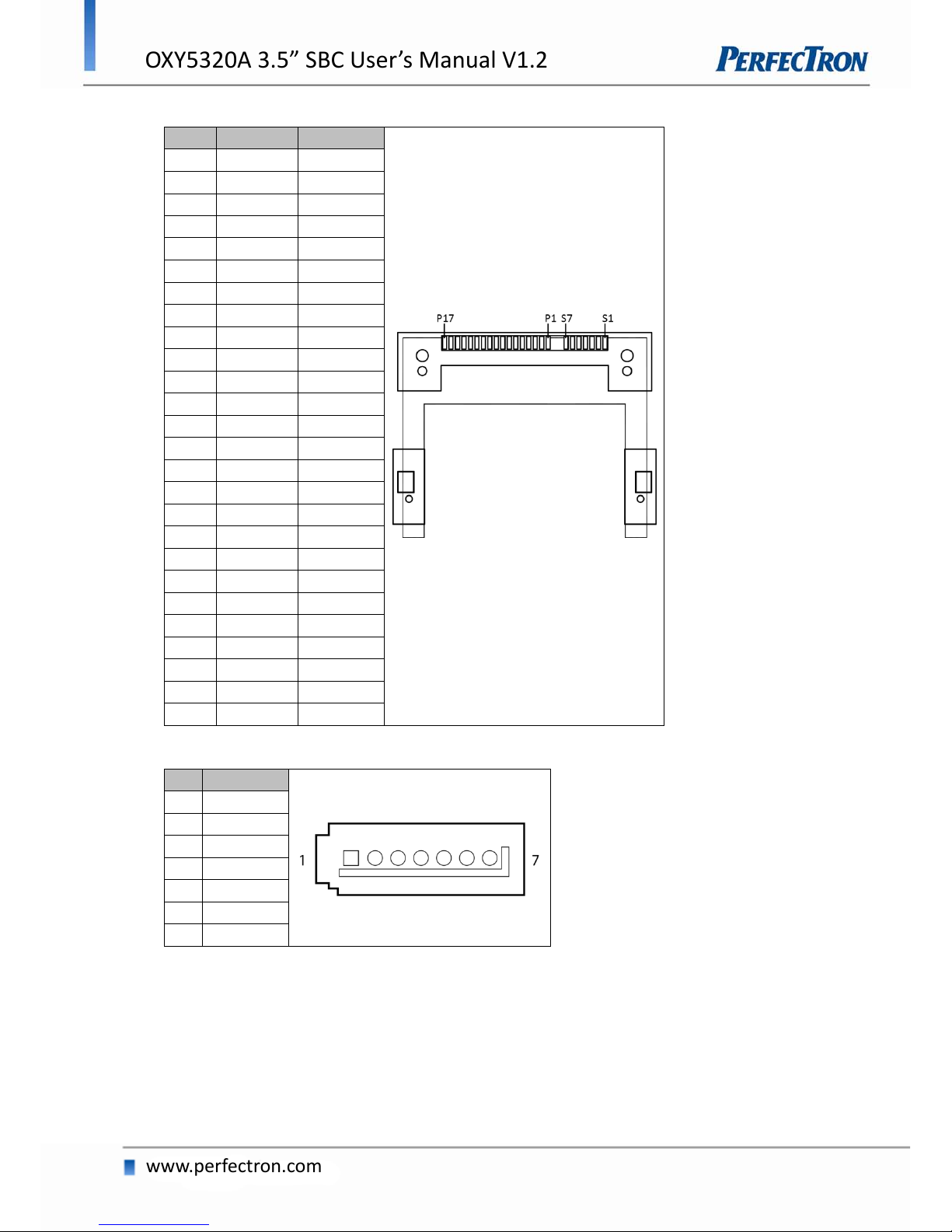
SATA1: Serial ATA 2.0 Connector
Pin
Definition
1
GND
2
TXP 3 TXN
4
GND
5
RXN
6
RXP
7
GND
18
OXY5320A 3.5” SBC User’s Manual V1.2
www.perfectron.com
Chapter 3: Getting Started
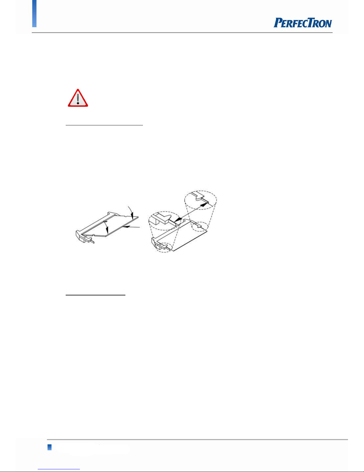
3.1 Installing System Memory
The OXY5320A supports DDR3 800/1066 SO-DIMM.
Disconnect
all power supplies to the board before installing a memory
module to prevent damage to the board and memory module.
To install a memory module:
1. Located the memory module slots on the motherboard.
2. Push the socket retaining clips outward to unlock the slots.
3. Align the memory module with the socket to make sure the notch aligns with the
slot key on the socket.
4. Insert the module firmly into the desired slot until the retaining clips lock and
secure the memory module.
3.2 Installing the CFast card
The OXY5320A built-in CFast socket
To install a CFast card:
1. To install a CFast card into OXY5320A, align the notches on the card with the
CFast socket.
2. Then firmly insert the card into the socket until it is completely seated. The label
side should be facing away from the board.
19

OXY5320A 3.5” SBC User’s Manual V1.2
www.perfectron.com
Chapter 4: AMI BIOS UTILITY
This chapter provides users with detailed descriptions on how to set up a basic system
configuration through the AMI BIOS setup utility.
4.1 Starting
To enter the setup screens, perform the following steps:
Turn on the computer and press the <Del> key immediately.
After the <Del> key is pressed, the main BIOS setup menu displays. Other setup
screens can be accessed from the main BIOS setup menu, such as the Chipset and
Power menus.
4.2 Navigation Keys
The BIOS setup/utility uses a key-based navigation system called hot keys. Most of the
BIOS setup utility hot keys can be used at any time during the setup navigation process.
Some of the hot keys are <F1>, <F10>, <Enter>, <ESC>, and <Arrow> keys.
Some of the navigation keys may differ from one screen to another.
Left/Right The Left and Right <Arrow> keys moves the cursor to select a menu.
Up/Down The Up and Down <Arrow> keys moves the cursor to select a setup
screen or sub-screen.
+− Plus/Minus The Plus and Minus <Arrow> keys changes the field value of a
particular setup setting.
Tab The <Tab> key selects the setup fields.
F1 The <F1> key displays the General Help screen.
F10 The <F10> key saves any changes made and exits the BIOS setup
utility.
Esc The <Esc> key discards any changes made and exits the BIOS setup
utility.
Enter The <Enter> key displays a sub-screen or changes a selected or
highlighted option in each menu.
20
OXY5320A 3.5” SBC User’s Manual V1.2
www.perfectron.com
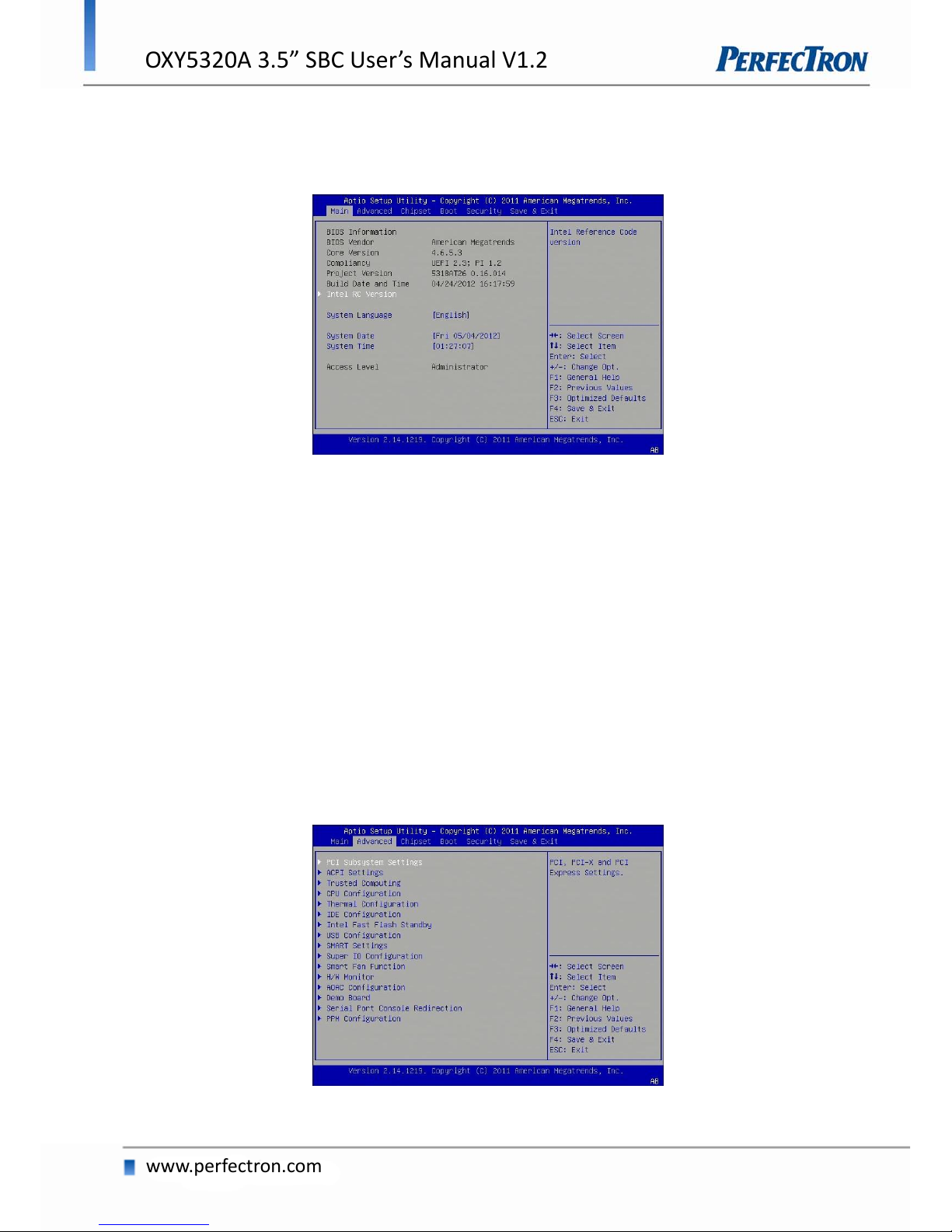
4.3 Main Menu
The Main menu is the screen that first displays when BIOS Setup is entered, unless an
error has occurred.
You could setup these items on the Main menu:
System Language: Select this option to set the system language
System Date: Select this option to set the system date.
System Time: Select this option to set the system time.
Use the <Arrow> keys to enter the appropriate time and date. Press the <Tab> key or
the <Arrow> keys to move between fields. The date setting must be entered in
MM/DD/YY format. The time setting is entered in HH:MM:SS format.
Access Level
Displays the access level of the current user in the BIOS.
4.4 Advanced Menu
This section allows you to configure and improve your system and allows you to set up
some system features according to your preference.
21

OXY5320A 3.5” SBC User’s Manual V1.2
www.perfectron.com
4.4.1 PCI Subsystem Settings
This section allows you to configure the PCI, PCI-X and PCI Express settings.
PCI Latency Timer
Set this value to change the PCI Bus clocks. Default is 32 PCI Bus clock
VGA Palette Snoop
Set this value to enable or disable the VGA Palette snoop. Default is disable
PERR# Generation
Set this value to enable or disable PERR# generation. Default is disable
SERR# Generation
Set this value to enable or disable SERR# generation. Default is disable
4.4.2 ACPI Settings
System ACPI Parameters.
Enable ACPI Auto Config
Enable/disable BIOS ACPI Auto Configuration. Default is Disable
22
OXY5320A 3.5” SBC User’s Manual V1.2
www.perfectron.com
ACPI Sleep State
Select the highest ACPI sleep state the system will enter when the SUSPEND button is
Selected. The Default value is set as S3 (Suspend to RAM).
Lock Legacy Resources
Enables or Disables System Lock of Legacy Resources.
Options: Disabled (Default) / Enabled
S3 Video Repost
Enable or disable S3 Video Repost.
Options: Disabled (Default) / Enabled
4.4.3 Trusted Computing
This option allows the user to modify settings related to the optional Trusted
Platform Module.
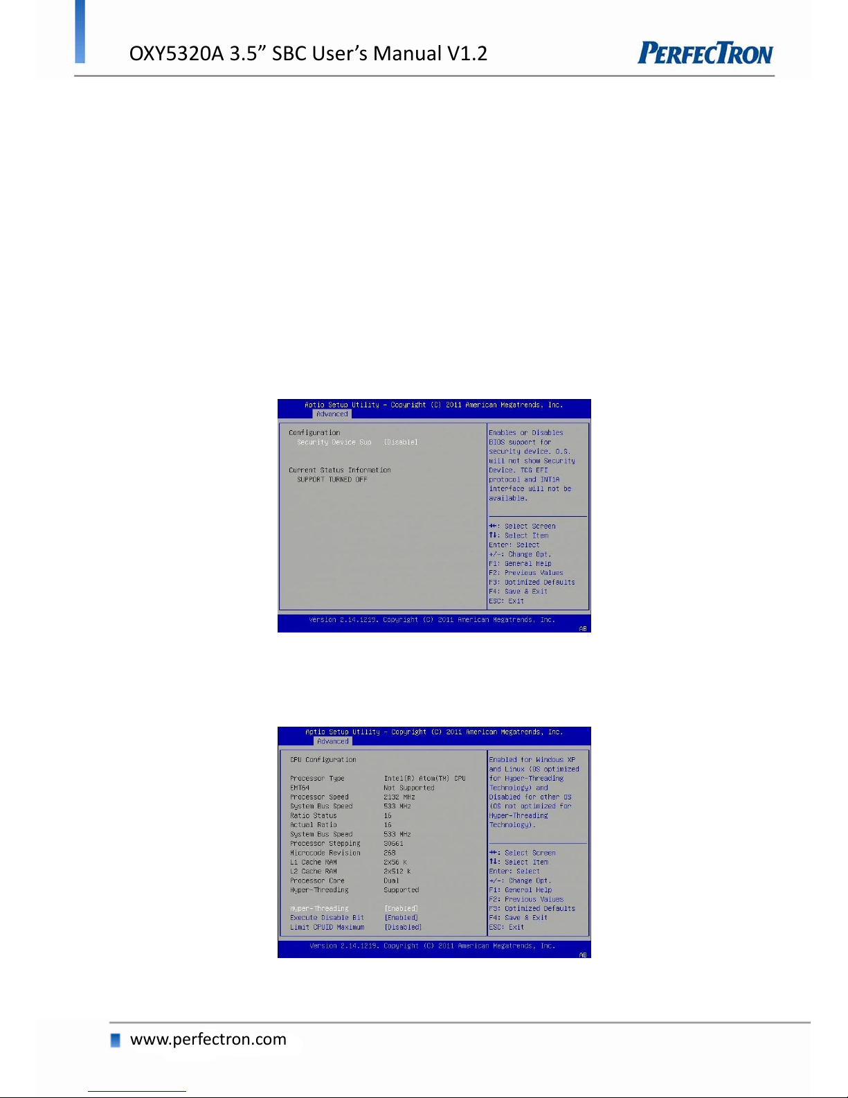
4.4.4 CPU Configuration
This option allows the user to view and configure the settings of the CPU installed on the
computer system.
23
OXY5320A 3.5” SBC User’s Manual V1.2
www.perfectron.com
Processor Type
This option allows the user to view the information of the CPU installed on the hardware
platform.
Processor Speed
This option allows the user to view the speed of the CPU installed on the hardware
platform.
System Bus Speed
This option allows the user to view the Front Side Bus (FSB) speed of the CPU.
Processor Stepping
This option allows the user to view the stepping information of the CPU.
L2 Cache RAM
This option allows the user to view the amount of L2 Cache on the CPU.
Hyper-Threading
This option allows the user to enable or disable the HyperThreading™ support of the
Intel® Pentium® 4 HT processor. By default this setting is enabled. This setting should be
disabled in Microsoft™ Windows 2000 based systems.
Execute Disable Bit
XD can prevent certain classes of malicious buffer overflow attacks when combined with
a supporting OS (Windows Server 2003 SP1, Windows XP SP2, SuSE Linux 9.2, RedHat
Enterprise 3 Update 3.)
Limit CPUID Maximum
Disabled for Windows XP.
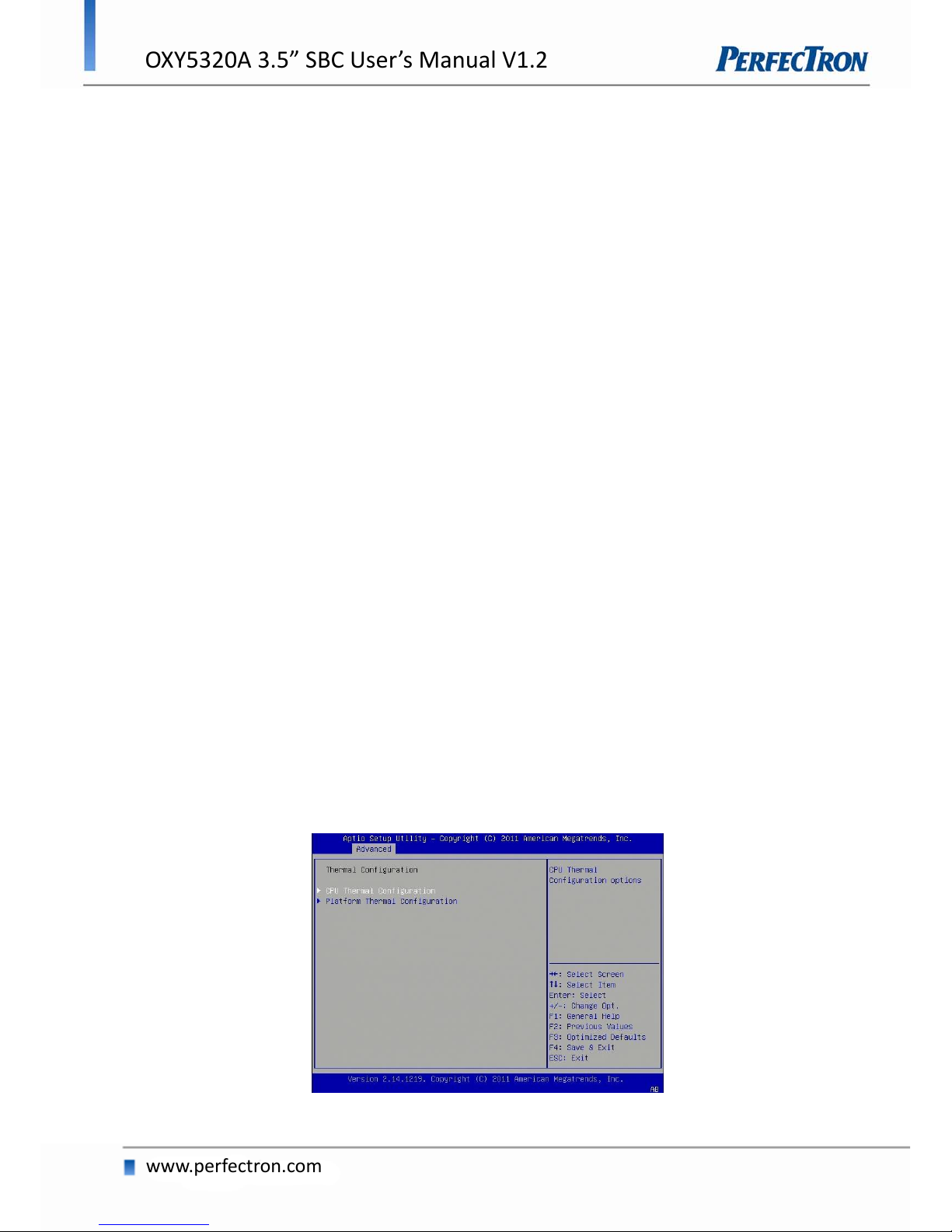
4.4.5 Thermal Configuration
This option allows the user to view and configure the settings of the CPU installed on the
computer system.
24

OXY5320A 3.5” SBC User’s Manual V1.2
www.perfectron.com
4.4.6 IDE Configuration
You can use this option to select options for the IDE Configuration Settings.
SATA Controller(s)
This item allows users to enable or disable the SATA controller(s).
Configure SATA As
IDE This is option configures the Serial ATA drives as Parallel ATA physical
storage device.
RAID This option allows you to create RAID or Intel Matrix Storage
configuration on Serial ATA devices.
AHCI This option configures the Serial ATA drives to use AHCI (Advanced
Host Controller Interface). AHCI allows the storage driver to enable the
advanced Serial ATA features which will increase storage performance.
4.4.7 Intel Fast Flash Standby
This setting allows the user to enable or disable iFFS
25

OXY5320A 3.5” SBC User’s Manual V1.2
www.perfectron.com
4.4.8 USB Configuration
This option allows the user to view and configure the settings of the USB configuration
parameters.
USB Devices
Legacy USB Support
This enables Legacy USB Support, the following tables outlines the different modes of
this feature:
Option Description
Auto This option disables legacy support if no USB devices are connected
Enable This option will enable Legacy USB support.
Disable This option will keep USB devices available only for EFI applications.
Legacy USB Support
Enable the support for legacy USB. Auto option disables legacy support if no
USB devices are connected.
EHCI Hand-off
This is a workaround feature for Operating Systems without EHCI hand-off support. The
EHCI ownership must be claimed by EHCI Driver.
Option Description
Enable This option enables EHCI hand-off support.
Disable This option disables EHCI hand-off support.
USB transfer time-out
Set the time-out value for Control, Bulk, and Interrupt transfers.
Device reset time-out
Set USB mass storage device Start Unit command time-out value.
26

OXY5320A 3.5” SBC User’s Manual V1.2
www.perfectron.com
Device power-up delay
Sets the maximum time the device will take before it properly reports itself to the
Host Controller. 'Auto' uses a default value: for a Root port it is 100 ms, for a Hub port
the delay is taken from the Hub descriptor.
4.4.9 SMART Settings
SMART (Self-Monitoring, Analysis and Reporting Technology) is a monitoring system for
computer hard disk drives to detect and report on various indicators of reliability, in the
hope of anticipating failures. SMART. failure messages might indicate the need to replace
the storage device.
4.4.10 Super IO Configuration
Set Parameters of Serial Ports. User can Enable/Disable the serial port and Select an
optimal settings for the Super IO Device.
Serial Port 0-4 Configuration
Use this item to enable or disable the onboard serial port.
Parallel Port configuration
Use this item to enable or disable the onboard parallel port.
27

OXY5320A 3.5” SBC User’s Manual V1.2
www.perfectron.com
4.4.11 Smart Fan Function
Use this feature to control CPU/System Temperature vs. Fan speed. When enabling
Smart Fan function, Fan speed is controlled automatically by CPU/System temperature.
This function will protect CPU/System from overheat problem and maintain the system
temperature at a safe level.
4.4.12 H/W Monitor
This section is used to monitor hardware status such as temperature, fan
speed and voltages.
CPU Temperature
Detects and displays the current CPU temperature.
System Temperature
Detects and displays the current system temperature.
Fan1 Speed
Detects and displays the current CPU fan speed.
28

OXY5320A 3.5” SBC User’s Manual V1.2
www.perfectron.com
4.4.13 AOAC Configuration
This item allows users to enable or disabled AOAC function.
4.4.14 Demo Board
This item helps users for CRB test.
4.4.15 Serial Port Console Redirection
This setting allows the user to enable or disable console redirection
29

OXY5320A 3.5” SBC User’s Manual V1.2
www.perfectron.com
Console Redirection
Enabling or disabling of the serial port on the module is specified in the Advanced
Configuration menu. Available option are: Disabled, Enabled
4.4.16 PPM Configuration
This item allows users to enable or disabled Intel SppedStep.
EIST
This item allows users to enable or disabled Intel SpeedStep function.
CPU C state Report
This item allows users to enable or disabled CPU C state report to OS.
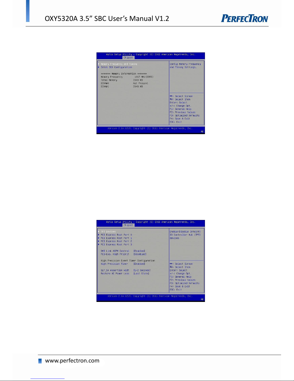
4.5 Chipset
This section allows you to configure and improve your system and allows you to set up
some system features according to your preference.
30
OXY5320A 3.5” SBC User’s Manual V1.2
www.perfectron.com
Host Bridge
This section is used to configure the host bridge features.
Memory Frequency and Timing
Configures memory frequency and timing settings
Intel IGD Configuration
Configures the options for Intel IGD function.
Memory Information
Detects and displays information on the memory installed in the system.
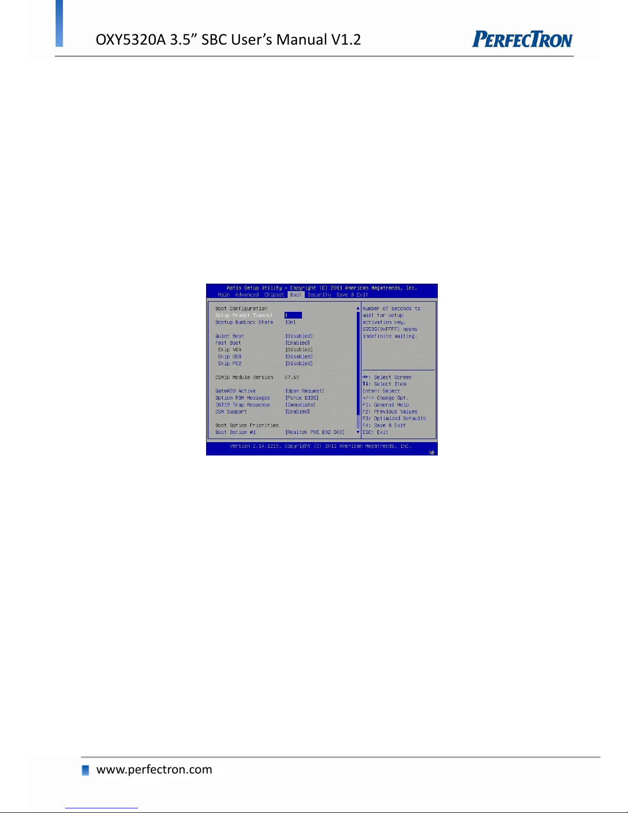
South Bridge
This item shows the South Bridge Parameters.
High Precision Event Timer Configuration
Enable or Disable the High Precision Event Timer.
SLP_S4 Assertion Stretch Enable
Select a minimum assertion width of the SLP_S4# signal.
31
OXY5320A 3.5” SBC User’s Manual V1.2
www.perfectron.com
Restore AC Power Loss
Options are Power Off, Power On and Last State.
Power Off When power returns after an AC power failure, the system’s power is off.
You must press the power button to power-on the system.
Power On When power returns after an AC power failure, the system will
automatically power-on.
Last State When power returns after an AC power failure, the system will return to
the state where you left off before power failure occurs. If the system’s
power is off when AC power failure occurs, it will remain off when power
returns. If the system’s power is on when AC power failure occurs, the
system will power-on when power returns.
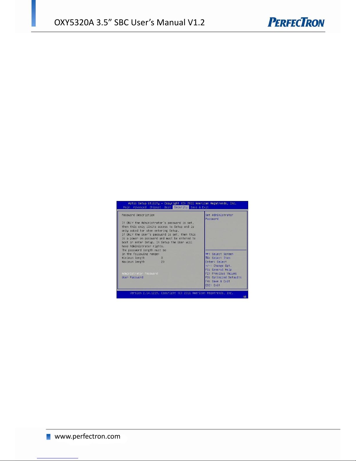
4.6 Boot Setting
Use this menu option to configure your boot settings
Setup Prompt Timeout
Selects the number of seconds to wait for the setup activation key.
65535(0xFFFF) denotes indefinite waiting.
Bootup NumLock State
This allows you to determine the default state of the numeric keypad. By default, the
system boots up with NumLock on wherein the function of the numeric keypad is the
number keys. When set to Off, the function of the numeric keypad is the arrow keys.
Quiet Boot
Set this value to allow the boot up screen options to be modified between POST
messages or OEM logo.
Fast Boot
Enable/Disable faster booting to reduce POST time.[Disabled] performs a complete set
of system initialization tasks
32
OXY5320A 3.5” SBC User’s Manual V1.2
www.perfectron.com
GateA20 Active
The CPU address bit 20 is controlled by a signal called gateA20. ften gatea20 signal is
generated by a peripheral controller (E.g. keyboard Controller) which is a part of the
overall system.
Optional ROM Messages
Set display mode for Option ROM. Based on this value it displays the messages from
Option ROM
INT19 Trap Response
Enable: Allows Option ROMs to trap Int 19.
Boot Option Priorities
This option shows the priorities of the boot options. User can change the priorities by
selecting the particular boot option. The boot option selected in Boot option #1 will be
the first priority, followed by second, third and so on.
4.7 Security
Use the Security Menu to establish system passwords
Administrator Password
Select this to reconfigure the administrator’s password.
User Password
Select this to reconfigure the user’s password.
33
OXY5320A 3.5” SBC User’s Manual V1.2
www.perfectron.com
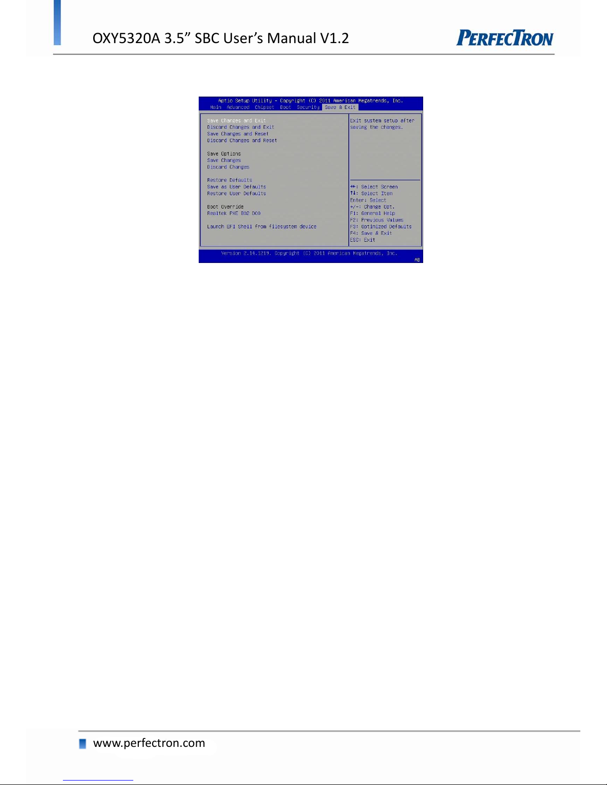
4.8 Save and exit
Save Changes and Exit
Exit system setup after saving the changes.
Disacard Changes and Exit
Exit system setup without saving any changes.
Save Changes and Reset
Reset the system after saving the changes.
Discard Changes and Reset
Reset system setup without saving any changes.
Save Changes
Save Changes done so far to any of the setup options.
Discard Changes
Discard Changes done so far to any of the setup options.
Restore Defaults
Restore/Load Defaults values for all the setup options.
Save as User Defaults
Save the changes done so far as User Defaults.
Restore User Defaults
Restore the User Defaults to all the setup options.
Boot Override
Pressing ENTER causes the system to enter the OS.
Launch EFI Shell from file system device
To launch EFI shell from a file system device, select this field and press <Enter>.
34
 Loading...