

Page 1
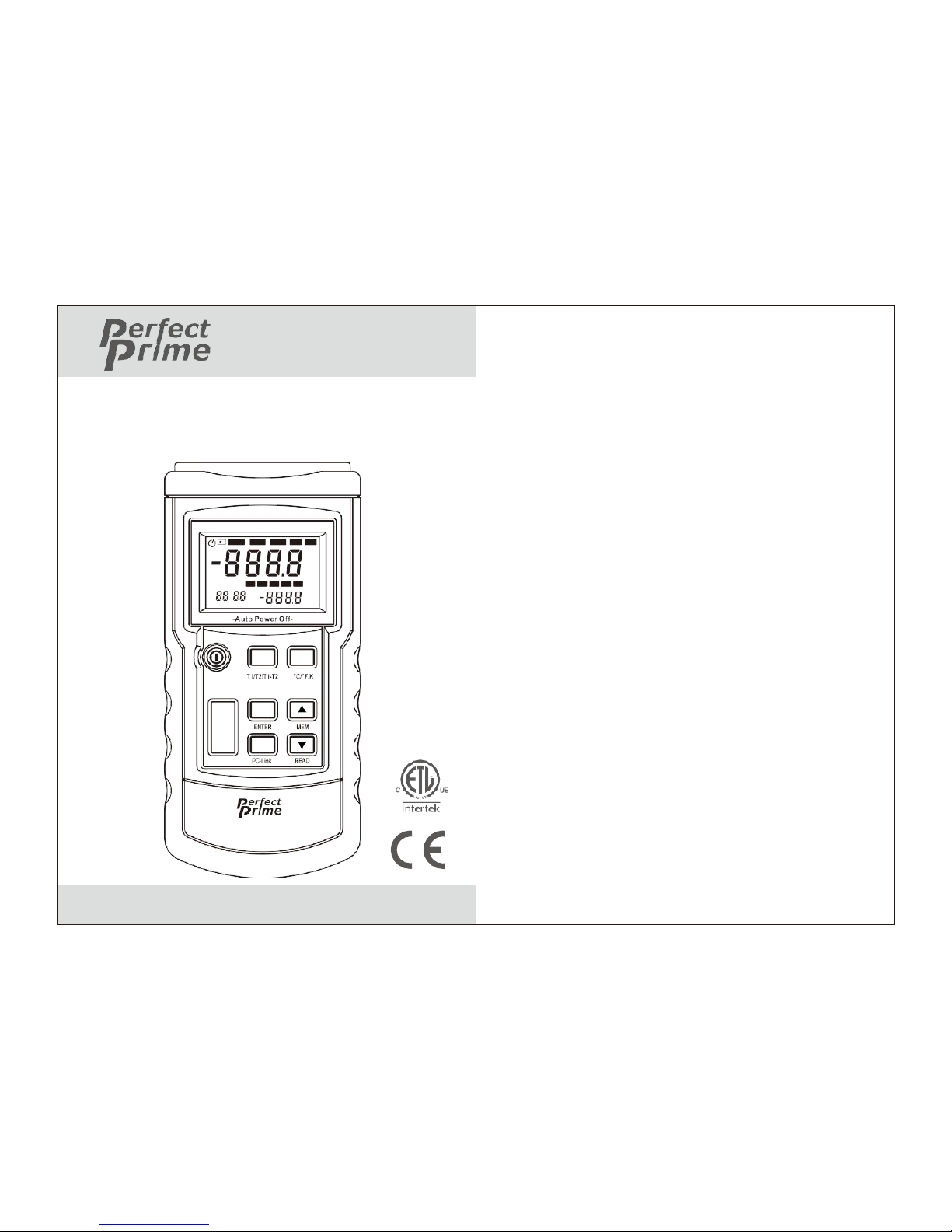
TC2100
Digital Thermometer
User’s Manual
OFFSET SETUP R EAD REC HOLD
T1T2 K
T1-T2
°F
°C
mV
TYPE KJTER SN
USB MAX M IN AVG MEN
K
INTERVAL hour:min
:
T1 T 2
°F
CAL min:sec
°C
POWER
HOLD
MAX
AVG
MIN
SETUP
THERMO METER
Page 2
CONTENTS
1.
Safety Information
.......................................
1
2.
Product Overview
........................................
3
3
.Recognize Meter
..........................................
4
3.1 Component.......................................................4
3.2 Display...............................................................5
3.3 Keys Description............................................. 6
4.
Setting Meter................................................8
4.1 SETUP Option
.................................................
8
4.2 SETUP Option Setting………..…………….9
5.
Using The Meter.........................................12
5.1 Connecting thermocouple.
..........................
12
5.2 Displaying Temperature.
.............................
12
5.3 Data Hold.
......................................................
12
CONTENTS
5.4 Viewing MAX,
MIN and AVG Readings.............................. 12
5.5 Use Offset value ToAdjust
Temperature probe error.............................13
5.6 User Self-Calibration.....................................13
6.
Data Storage.
..............................................
15
6.1 Data Storage
..................................................
15
6.2 Data Reading................................................. 15
6.3 Clearing Stored Data....................................16
7.
Data Transmission.
...................................
16
8.
Meter Maintenance.
...................................
16
8.1 Replace Battery............................................. 16
8.2 Clean.
..............................................................
16
9. Technique Data.......................................... 17
Page 3
1.Safety Information
In order to use the thermometer safely and correctly,
please read this manual carefully first, especially the
“Safety Information” part. It is recommended to keep
the manual at hand so that one can refer to it at any time.
Warning
Warning indicates a situation/action which may cause
danger to users. To avoid any possible accidents or
injury, please strictly follow the procedures below:
1. Before using, check if there is any missing part or
damages on the case. Do not use if it is damaged.
2. Disconnect thermometer and thermocouple before
opening the meter case.
3. When the battery indicator appears, the battery
should be replaced.
4. If the product works abnormally, stop using it.
Protective equipment may be damaged. Send
the meter to a designated repair site.
5. Do not use the product in explosive gas, vapor or
dusty environment.
6. Do not apply voltage exceeding the rated voltage
marked on the product (30V).
7. Insulated thermocouple should be used.
8. Thermometer should be repaired only using manufacturers
replacement parts.
9. Do not use if the case is opened.
Caution
Situations/actions which may cause damage to the meter are
listed below. To prevent damage, use the meter carefully.
1. Select appropriate thermocouple probes, function grade
and measuring range before using.
2. Ensure there is no difference between
two lines when using dual-line measurement.
3. Do not charge the batteries.
4. Note the “+” & “-” polarities when installing batteries.
01
02
Page 4
Electrical Symbols
2. Product Overview
This product includes thermocouple probes with
microprocessor as the temperature sensor. It has the
following features:
•
Suitable for various thermocouples probes: K, J, T,E,
R, S, N.
•
Different temperature units: °C, °F and K (Kelvin)
•
Maximum, minimum and average value measurement
•
Data hold
•
Thermocouple deviation compensation
•
Relative time display
•
Auto power-off (can be set by users)
•
Self-calibration (please refer to “User Self-
calibration” section carefully)
•
Automatically and manually save data
•
USB port
•
Dual-line input (T1, T2)
3. Meter Description
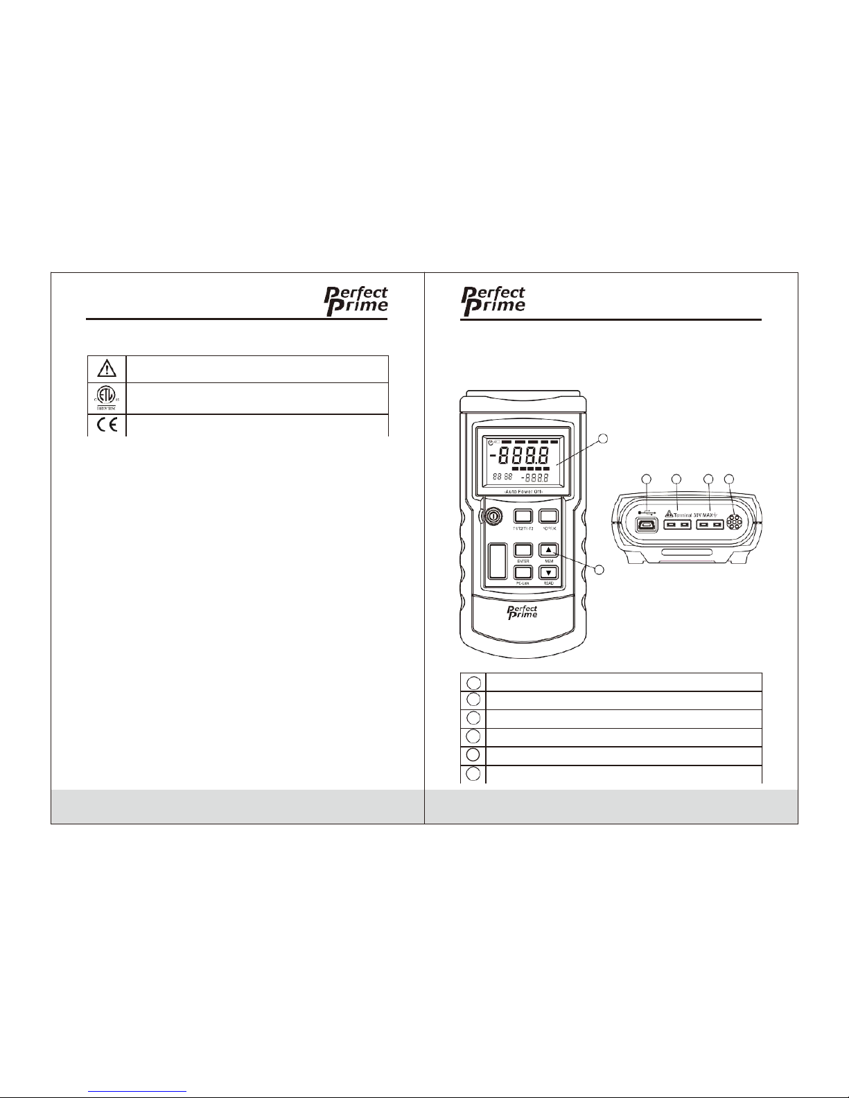
3.1 Components
5
OFFSET SETUP READ REC HOLD
T1 T2
K
T1-T2
°F
°C
mV
TYPE KJTERSN
USB MAX MIN AVG MEN
K
INTERVAL hour:min
:
T1 T2
°F
CAL min:sec
°C
POWER
HOLD
MAX
AVG
MIN
SETUP
6
THERMOMETER
1
2
- T1
+3- T2
+
4
03
04
Note-important safety information, refer to the
instruction manual.
Conforms to UL STD. 61010-1,
Certified to CSA STD C22.2 NO. 61010-1
Complies with European (EU) safety standards
1
USB port
2
Thermocouple probe T1 input
3
Thermocouple probe T2 input
4
Measure under normal temperature
5
Display
6
Key
Page 5
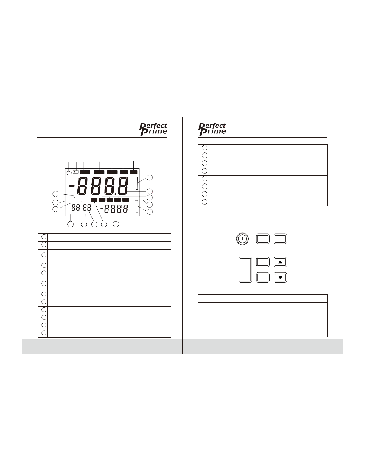
3.2 Display
1 2 3
OFFSE T
T1 T2
T1-T2
20
TYPE K JTERS N
19
INTERV AL hou r:min
18
:
CAL min: sec
17
16
4
SETUP
USB MAX
T1 T2
15 14
5
READ
MIN AVG
13
6
REC
MEN
7
HOLD
K
°F
°C
mV
K
°F
°C
8
9
10
11
12
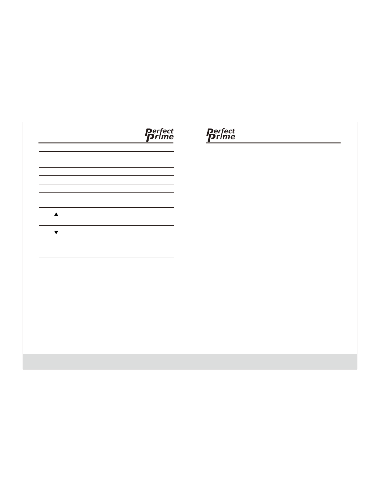
3.3 Keys Description
POWER
MAX
AVG
MIN
T1/T2/T1-T2
HOLD
ENTER
SETUP
PC-Link
C°/F°K
MEM
READ
05
06
1
Automatic power-off indicator
2
Low battery indicator: Battery should be replaced.
3
Thermocouple measurements include deviation
value
4
Status setup indicator with flashing display
5
Indicator to display saved data
6
Indicator to save data automatically with flashing
display
7
Data hold state
8
Main display unit
9
Main display
10
MAX, MIN, AVG
11
Indicator to save data
12
Auxiliary display unit
13
Auxiliary display
14
USB port
15
Time display
16
Indicate time display min: sec
17
Indicate calibrating state
18
Indicate auto-save time setting
19
Indicate time display hour: min
20
Indicate thermocouple probe type
POWER
Power on/off thermometer
T1/T2/
T1-T2
Select to display T1, T2 and T1-T2
(temperature difference measurement)
on main/auxiliary screen
˚C/˚F/K
Unit selection: Celsius (°C),
Fahrenheit (°F), Kelvin (K)
Page 6
4. Setting Meter
4.1 SETUP Option
1. Press the SETUP key to enter setup mode.
-->“
SETUP
” symbol will flash on the screen.
2. Press again to switch setting states.
3. Save all previous settings before exiting.
-->If the meter is turned off in the process of saving
settings, changes will not be saved.
4. Changed settings will function immediately after
exiting setup mode.
07
08
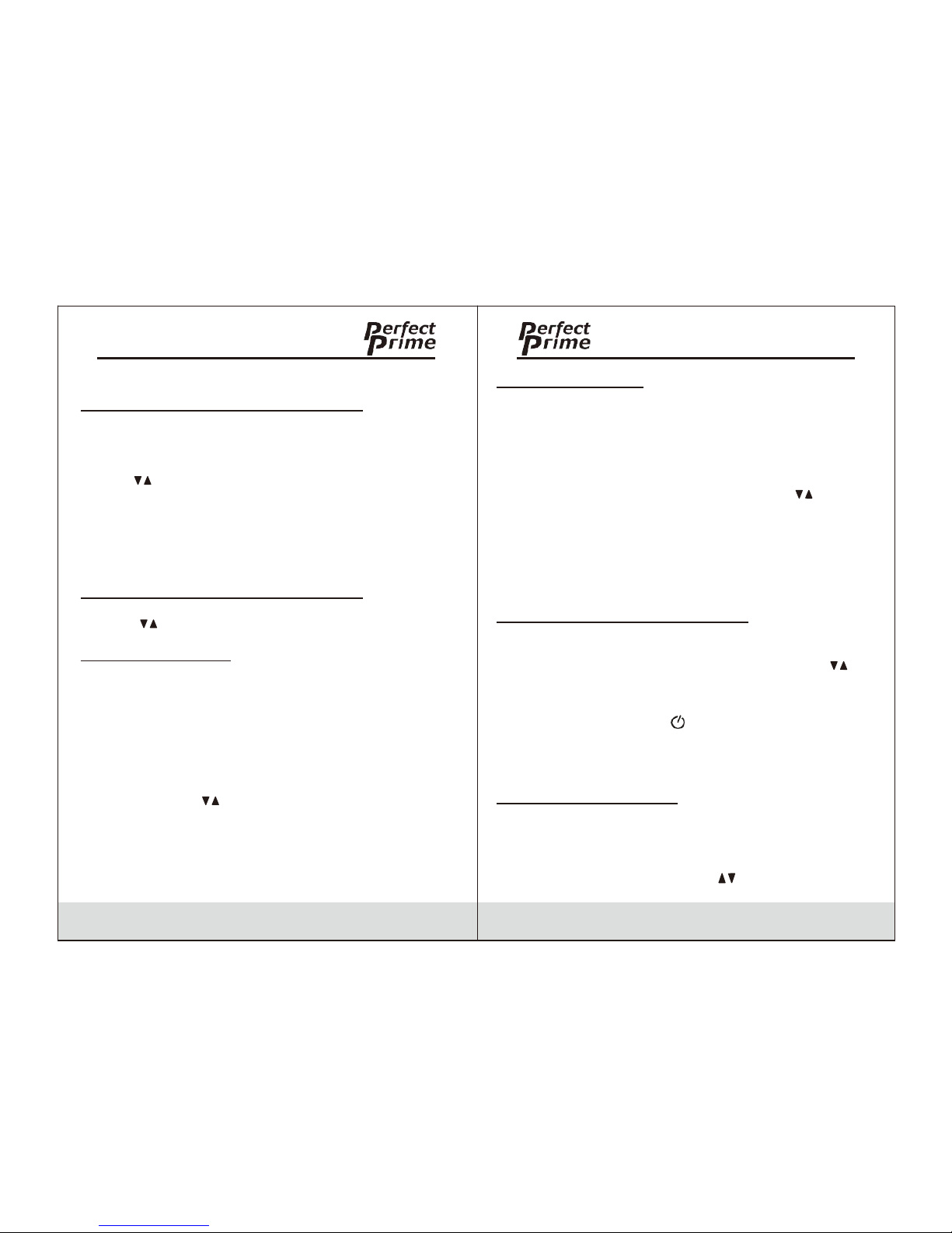
MAX/MIN
/AVG
View maximum, minimum and average
value. Press and hold to close
HOLD
Data hold
ENTER
To confirm, see user setting for details
SETUP
To set, see user setting for details
PC-Link
Press and hold to open USB, press
and hold again to turn off
To change setting options/add
functions, see specific operation for
details
To change setting options/reduce
functions, see specific operation for
details
READ
Read saved data
MEM
Save current data
Page 7
4.2 SETUP Option Setting
A. Data storage interval setting (INTERVAL):
1. Press the SETUP key to enter the data storage
interval setting mode.
-->“
SETUP
” will flash on the screen.
2. Use to change automatic data storage time interval.
3. Maximum interval time is 59:59.
4. Minimum interval time is 00:00.
-->00:00 enables auto data storage function.
-->It can only be stored manually.
B. Thermocouple probe type setting (TYPE):
1. Enter thermocouple probe type setting mode.
2. Use to set thermocouple probe types: K, J, T, E, R, S, N.
C. OFFSET (T1) setting:
Users can adjust the thermometer displayed value to
compensate for the thermocouple probe error. See
“Adjust the
temperature sensor error with deviation value” section.
Allowable adjustment range is ±6°C. After entering
OFFSET (T1) setting state, the offset value setting can
be changed with .
Note: When the offset value is not required, please
restore the value to 0.0.
Note: Changing thermocouple probe type will
automatically restore offset value to 0.0.
D. OFFSET(T2) setting:
Users can adjust the thermometer to show value tahts
compensated for the thermocouple probe error. See
“Adjust the
temperature sensor error with deviation value” section.
Adjustment range is ±6°C. After entering OFFSET (T2)
setting state, offset value can be changed with .
Note: When this offset value is no longer required,
please restore this offset value to 0.0.
Note: Changing the thermocouple probe type will
automatically restore offset value to 0.0.
E. Automatic power-off time setting (P):
1. Enter the automatic power-off time setting mode.
-->“P-” will show on the screen.
2. Set automatic power-off time (5 to 60 minutes) with .
3. Set the sleep time <5 minutes to show “OFF”.
--> This will turn off auto power-off function.
4. If the function is active, “ ” will show on screen.
-->Auto power-off time counts from last key operation.
-->In auto data recording & PC communication state, it
will not enter automatic power-off state.
F. System time setting (S-T):
System time is the time from powering on. It will
automatically be cleared after power failure.
1. Enter the system time setting.
-->“S-T” will show on screen.
2. The system time can be set with .
09
10
Page 8
3. Press ENTER to select time format (hr:min/min:sec)
4. The system time is the current running time if not changed.
G. Power frequency setting (LinE):
Toget the best result, please set the meter's power
frequency to local frequency.
1. Enter the power frequency setting.
--> “LinE” will show on the screen.
2. Select & set interference frequency to 50/60Hz with .
H. Normal temperature compensation (NTC):
1. Enter normal temperature compensation
(NTC) switch setting mode.
-->“NTC” will show on the screen.
2. ON/OFF can be set for normal temperature
compensation with .
3. Meter automatically restores to ON state after reboot.
I. Auto-calibration switch setting (CAL):
1. Enter the ON/OFF setting of auto-calibration (CAL).
-->“CAL” will show on the screen.
2. ON/OFF can be set for calibration function with .
By setting this item to ON, users can enter the calibration
mode. See “User Self-Calibration” for details.
Note: Use this function with caution!
J. Data clearing (CLr):
1. Enter the data clearing (CLr) mode.
-->“CLr” will show on the screen.
2. Press “ENTER” to clear all recorded data.
-->“CLr” will flash on the screen.
-->Flashing will stop after data is cleared.
5. Using The Meter
5.1 Connecting Thermocouple probe
1.
Insert the thermocouple probe to input jack.
2.
Press the power key to turn on the meter.
3.
Set the thermocouple probe type to be consistent
with the inserted thermocouple probe type.
Note: If the thermocouple probe is not connected to
the
selected input end/the thermocouple probe is
“open”/
exceeds measuring range, “OL” will show on
the thermometer.
5.2 Displaying Temperature
1.
Press °C/°F/K key to select temperature unit.
2.
Put the thermocouple probe into the testing position.
3.
Measurement results will display on screen.
5.3 Data Hold
1.
Press HOLD to keep reading on screen.
-->“
HOLD
” will show on the screen.
2.
Press again to close “HOLD” function and restore
measurement state.
5.4 Viewing MAX, MIN and AVG Readings
1.
Press MAX/MIN/AVG key to view MAX, MIN and AVG
readings.
2.
Hold MAX/MIN/AVG key to exit MAX/MIN/AVGview
11
12
Page 9

5.5 Use offset Value ToAdjust
Temperature Probe Error
Use OFFSET (T1) & OFFSET (T2) in the SETUP to adjust
the meter readings to compensate for thermocouple probe
error.
1.
Put the thermocouple probe in a known and stable
temperature environment (such as in ice bath or dry well
calibrator).
2.
Stabilize the temp. reading.
3.
In SETUP option, adjust OFFSET value until the temp.
reading on the auxiliary display is consistent with
calibrated temp. (see “SETUP Option Setting”).
5.6 User Self-Calibration
The meter can be calibrated in calibration mode.
Calibration points & methods are shown below:
1.
Calibration point:
a)
Normal Temp. 25°C
b)
T1 input channel, 0μV and 40.000mV
c)
T2 input channel, 0μV and 40.000mV
2.
Calibration methods:
a)
Put the meter into a thermotank with the temp.
of 25°C for 3~5 min.
b)
Power on to stabilize the thermometer.
c)
Set self-calibration(CAL) to ON in “SETUP” then exit.
It will return to calibration state.
d)
Adjust the screen temp. with keys until the temp. is
consistent with the thermotank.
e)
Press “ENTER” to save current calibration value.
f)
Press “T1/T2/T1-T2” / “TC TYPE” key to switch to
T1 measurement channel.
g)
Input 0μV in T1 measurement channel.
h)
After stabilizing, press “ENTER” to save current
calibration value.
i)
Input 40.000mV in T1 measurement channel.
j)
After stabilizing, press “ENTER” to save current
calibration value.
k)
Press “T1/T2/T1-T2” to switch to T2 measurement
channel.
l)
Input 0μV in T2 measurement channel.
m)
After stabilizing, press “ENTER” to save current
calibration value.
n)
Input 40.000mV in T2 measurement channel.
o)
After stabilizing, press “ENTER” to save current
calibration value.
p)
Power off and restart to complete calibration.
Note: Make sure the standard source is accurate,
then make calibration.
Note: If the meter is inaccurate due to inaccurate
calibration sources, users bears the liability.
Page 10

13
14
Page 11
6. Data Storage
6.1Data Storage
Manual storage is in the normal measurement mode
and data storage interval (INTERVAL) is set to 00:00.
1. Press the “MEM” key to store an item of
data.
2. Storage location will be the smallest no. in
the unused storage space.
3. If storage space is full of data, “FULL” will
be displayed for 2s.
B. Automatic storage is in normal measurement mode
and data storage interval is not set to 00:00.
Press the “MEM” key to start storing data.
Storage location will be the smallest no. in the
unused storage space.
1. “ REC ” symbol will flash on screen.
2. Press the “MEM” again to stop storing data.
3. Each data storage time interval is the time
set in the
INTERVAL.
-->The mini. time interval can be set is 1s.
-->The maxi. is 59 minutes and 59s.
4. If storage space is full, “FULL” will be
displayed for 2s and no data will be stored.
6.2 Data Reading
In normal measurement mode, press “READ” key
to enter data reading mode.
6.3 Clearing Stored Data
Please refer to Data clearing (CLr) in 4.2 SETUP
Option Setting.
Data Transmission
Connect the thermometer to PC with data line.
Hold “PCLink” key.
-->“ USB ” symbol will show on screen.
-->The USB port is opened.
See data transmission protocol for details.
Note: After connecting the USB, the meter will be
powered by USB power supply and the meter's
power key is invalid; After disconnecting, the
USB key will become valid.
Meter Maintenance
8.1 Replace Battery
Turn off the power.
Unscrew the screw and remove the cover.
Replace with 9V battery.
Put battery cover back and tighten the screw.
8.2 Clean
Use a soft cloth/sponge to wipe the product surface
gently with a little soap water or commercial detergent.
Page 12

-->“ READ ” symbol will flash on the screen.
1. Press to read the next/previous data.
-->“ MEM ” and number will shown on auxiliary
display.
2. If there is no available storage space, “NULL”
will be displayed for 2s.
To avoid damage, do not immerse the thermometer in
water.
15
16
Page 13
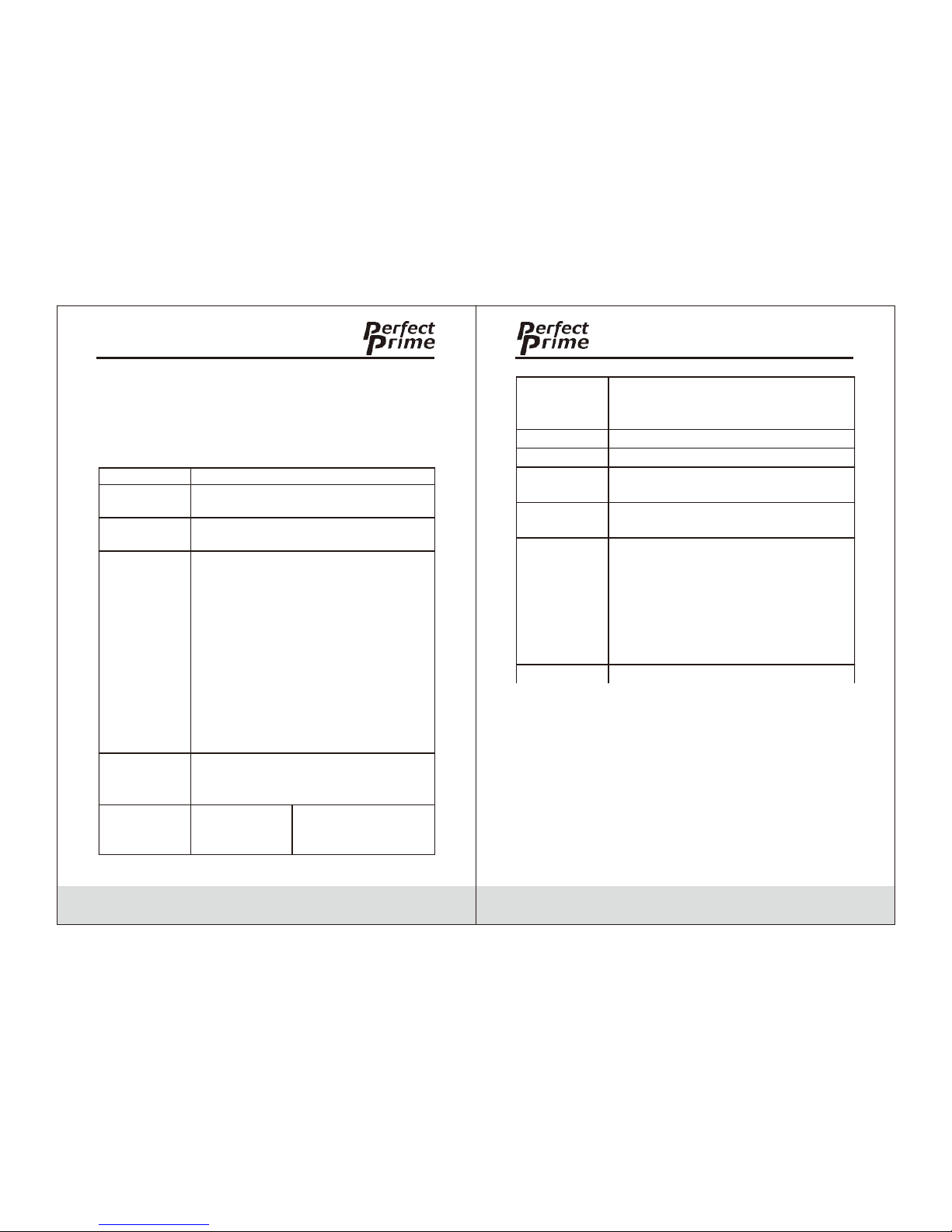
9.Technical Data
The indicator is accurate within the temp. range
(18°C-28°C) and relative humidity is <80%. Warranty
period is one year (thermocouple probe error not
included).
17
18
<-10°C: within +0.5°C; <-200°C:
within +1°C
T-type < -200°C for reference only
Time
Relative time
Data record
0~999, 1000 groups in total
Temperature
scale
ITS-90
Applicable
standard
NIST-175
Setting
functions
Recording interval setting*,
thermocouple type setting,
thermocouple probe offset setting,
automatic power-off time setting,
system time setting, power frequency
setting, temperature compensation
switch setting, self-calibration switch
setting, data clearing*
Power supply
9V Battery
Function
The meter
Thermocouple
probe type
K, J, T, E, R, S, N
Measurement
channel
T1/T2
Measurement
range
K: -200.0°C to +1372°C
-328.0°F to +2501°F
J: -210.0°C to +1200°C
-346.0°F to +2192°F
T: -250.0°C to +400°C
-418.0°F to +752°F
E: -150.0°C to +1000°C
-238.0°F to +1832°F
R: 0°C to +1767°C
32°F to +3212°F
S: 0°C to +1767°C
32°F to +3212°F
N: -200.0°C to +1300°C
-328.0°F to +2372°F
Display
resolution
0.1°C/ °F / K<1000° (1°C/ °F / K for
R-type and S-type)
1°C/ °F / K >1000°
Precision T1/
T2/T1-T2
±[0.5% +0.5°C]
K,J,T,E:±(0.2%+0.5°C)
R,S:±(0.2%+1°C)
N:±(0.2%+0.5°C)
Page 14
R-00-05-2312
 Loading...