

Page 1

XMS4A
LetRipp II
Engine Management System
DIY MANUAL
Version 2.1
Page 2

LETRIPP II XMS4A DIY MANUAL V2.1 www.perfectpower.com i
PERFECT POWER XMS4A – Engine Management System DIY MANUAL V2.1
Table of Contents: Page no:
1.
INTRODUCTION.................................................................................................1
2. PARTS SUPPLIED IN THE KIT...............................................................................1
3. WHY SHOULD YOU READ THIS MANUAL?...............................................................1
4. EXPLANATION OF XMS4 UNITS AVAILABLE............................................................2
5. TECHNICAL DETAILS ..........................................................................................3
5.1 FUEL INJECTION.............................................................................................3
5.2 IGNITION ......................................................................................................3
5.3 ACCELERATION ENRICHMENT...........................................................................4
5.4 INJECTOR/ENGINE PRIMING.............................................................................4
5.5 TRIGGER INPUTS............................................................................................4
5.6 BOOST CONTROL............................................................................................4
5.7 PRIME (FUEL).................................................................................................4
5.8 IDLE CONTROL...............................................................................................4
5.9 SETPOINT CONTROL .......................................................................................4
6. FEATURE EXPLANATION......................................................................................5
6.1 LAUNCH CONTROL..........................................................................................5
6.2 EXTERNAL SUPPLY TO SENSORS.......................................................................5
6.3 MAPS A / B....................................................................................................5
6.4 CALIBRATION.................................................................................................5
6.5 FUEL INJECTION MAP......................................................................................5
6.6 IGNITION MAP ...............................................................................................5
6.7 COMPENSATION MAP ......................................................................................5
6.8 BOOST CONTROL............................................................................................6
6.9 SETPOINT......................................................................................................6
6.10 MAXIMUM RECORDINGS..................................................................................6
6.11 ONBOARD LOGGING (COMING SOON)...............................................................6
6.12 COMMUNICATION CONNECTION .......................................................................6
6.13 USB DRIVERS SETUP.......................................................................................7
7. COMPUTER REQUIREMENTS ................................................................................7
8. PIN OUTS OF XMS4A UNIT ..................................................................................8
8.1 XMS4A PIN-OUT TABLE....................................................................................8
8.1.1 XMS4A IGNITION PIN-OUT CONNECTOR (6 PIN)..............................................8
8.1.2 XMS 4A INJECTION PIN-OUT CONNECTOR (8 PIN) ...........................................8
8.1.3 XMS 4A AUXILIARY CONNECTOR (4 PIN) ........................................................9
8.1.4 XMS 4A MAIN CONNECTOR (22 PIN) ..............................................................9
9. ASSESSING YOUR CAR’S FUEL SYSTEM...............................................................10
9.1 IS YOUR CAR READY FOR FUEL INJECTION?.....................................................10
9.2 HOW TO MAKE YOUR CAR READY FOR FUEL INJECTION .....................................10
9.3 CONCLUSION...............................................................................................11
10. ASSESSING YOUR ENGINE................................................................................11
10.1 COMPATIBLE TRIGGER WHEEL........................................................................11
10.2 CAMSHAFT SENSOR......................................................................................12
10.3 HOW TO INSTALL A COMPATIBLE WHEEL AND PICKUP SENSOR ..........................12
10.4 WHICH SENSORS ARE MISSING?....................................................................13
10.5 INJECTOR RESISTANCE .................................................................................13
10.6 MAKE SURE THE ENGINE HAS THE BASICS.......................................................14
10.7 CONCLUSION...............................................................................................14
11. WHERE TO FIT YOUR XMS4A?............................................................................14
11.1 SUITABLE PLACES ........................................................................................14
11.2 UNSUITABLE PLACES ....................................................................................15
11.3 CONCLUSION...............................................................................................15
12. WHERE TO FIT THE IGNITION AMPLIFIER? ..........................................................15
12.1 SUITABLE PLACES ........................................................................................15
12.2 UNSUITABLE PLACES ....................................................................................16
12.3 CONCLUSION...............................................................................................16
13. SCREENED CABLE............................................................................................16
13.1 WHAT IS A SCREENED CABLE?.......................................................................17
Page 3

LETRIPP II XMS4A DIY MANUAL V2.1 www.perfectpower.com ii
PERFECT POWER XMS4A – Engine Management System DIY MANUAL V2.1
13.2 WHY SHOULD I USE A SCREENED CABLE?........................................................17
13.3 WHAT SHOULD YOU USE A SCREENED CABLE ON?............................................17
14. CRANK SIGNALS - WHAT DO THEY LOOK LIKE?....................................................17
14.1 POSITIVE EDGE............................................................................................17
14.2 NEGATIVE EDGE...........................................................................................18
14.3 MAGNETIC...................................................................................................18
14.4 DIGITAL/HALL EFFECT...................................................................................18
15. TYPICAL SENSORS USED AND HOW TO WIRE THEM..............................................18
15.1 AMP............................................................................................................19
15.2 ENGINE TEMP...............................................................................................19
15.3 AIR TEMP ....................................................................................................20
15.4 THROTTLE POSITION ....................................................................................21
15.5 CRANK ANGLE SENSOR .................................................................................21
15.6 CAMSHAFT SENSOR......................................................................................22
15.7 CONCLUSION...............................................................................................22
16. TYPICAL DEVICES DRIVEN BY THE XMS4A...........................................................23
16.1 BOOST SOLENOID ........................................................................................23
16.2 FUEL PUMP RELAY.........................................................................................23
16.3 FAN RELAY...................................................................................................24
16.4 2 WIRE IDLE CONTROL MOTOR.......................................................................24
16.5 SHIFT LIGHTS..............................................................................................25
16.6 REV COUNTER..............................................................................................25
16.7 INJECTORS..................................................................................................25
16.8 IGNITION AMPLIFIERS...................................................................................26
17. IDLE CONTROL – IN MORE DETAIL .....................................................................27
17.1 TWO WIRE IDLE – SOFTWARE SETUP ..............................................................27
17.1.1 F3 – TWO WIRE IDLE FOR XMS4A.............................................................28
17.1.2 SHIFT F2 – SYSTEM DEF .........................................................................28
17.1.3 IDLE RPM TARGET..................................................................................29
17.1.4 SHIFT/F11 – 2WIRE IDLE........................................................................29
17.1.5 SETTING UP THE IDLE ............................................................................30
18. DWELL TIME....................................................................................................30
18.1 WHAT IS DWELL? .........................................................................................30
18.2 CAN IT DAMAGE YOUR COIL? .........................................................................30
18.3 DWELL SETUP VIA SOFTWARE........................................................................31
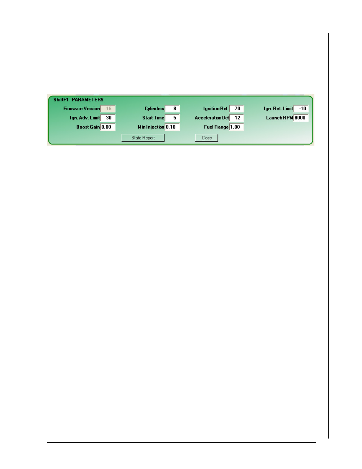
19. SETTING UP PARAMETERS.................................................................................32
20. SYSTEM DEFINITION........................................................................................33
21. SET POINTS ....................................................................................................34
21.1 USES ..........................................................................................................34
21.2 WIRING.......................................................................................................34
21.3 SETUP VIA SOFTWARE ..................................................................................35
22. CALIBRATION OF SENSORS...............................................................................35
22.1 AMP............................................................................................................36
22.2 ENGINE TEMP...............................................................................................36
22.3 AIR TEMP ....................................................................................................37
22.4 THROTTLE POSITION ....................................................................................37
22.5 CONCLUSION...............................................................................................37
23. RPM...............................................................................................................38
23.1 SETUP AND CALIBRATION VIA SOFTWARE .......................................................38
23.2 LIMIT..........................................................................................................38
23.3 CONCLUSION...............................................................................................39
24. WHAT TO DO BEFORE TRYING TO START THE ENGINE ..........................................39
24.1 IGNITION SETUP WITH TIMING MARKS AND TIMING LIGHT................................39
24.2 IGNITION ADJUSTMENT VIA SOFTWARE ..........................................................40
25. TIME TO START THE ENGINE.............................................................................40
25.1 FIRST THINGS TO DO WHEN CRANKING THE ENGINE........................................40
25.2 FIRST THINGS TO DISABLE WHEN THE MOTOR IS RUNNING ..............................40
25.3 IDLE SETUP .................................................................................................41
25.4 FUEL SETUP WITH AMP..................................................................................41
Page 4

LETRIPP II XMS4A DIY MANUAL V2.1 www.perfectpower.com iii
PERFECT POWER XMS4A – Engine Management System DIY MANUAL V2.1
25.5 CONCLUSION...............................................................................................43
26. LOOK HERE IF IT DOESN’T START......................................................................43
26.1 POSSIBLE REASONS AND COMMON CHECKS ....................................................43
27. TUNING YOUR XMS4A FOR THE FIRST TIME.........................................................44
27.1 OPTIONS.....................................................................................................44
27.2 TOOLS NEEDED............................................................................................44
27.3 FUEL TUNING...............................................................................................44
CO MEASUREMENTS.........................................................................................44
4 GAS ANALYSER.............................................................................................45
27.4 IGNITION TUNING ........................................................................................47
28. COLD START MAP.............................................................................................48
29. ACCELERATION ENRICHMENT............................................................................49
30. SETTING THE BOOST CONTROL UP.....................................................................49
30.1 CLOSED LOOP..............................................................................................49
30.2 VIA PWM .....................................................................................................50
31. LAUNCH CONTROL ...........................................................................................50
31.1 USES ..........................................................................................................50
31.2 SETUP VIA SOFTWARE ..................................................................................51
31.3 CONCLUSION...............................................................................................51
32. TROUBLESHOOTING.........................................................................................51
32.1 FUEL...........................................................................................................51
32.2 PRESSURE...................................................................................................51
32.3 IGNITION ....................................................................................................51
32.4 SPARK PLUGS ..............................................................................................52
32.5 COIL...........................................................................................................52
32.6 TWO WIRE COIL...........................................................................................52
32.7 THREE WIRE COIL ........................................................................................52
32.8 FOUR WIRE COIL:.........................................................................................53
32.9 TRIGGER WHEEL ..........................................................................................53
32.10 TRIGGER SENSOR .....................................................................................53
32.11 ENGINE FAILURE, NO COMPRESSION...........................................................54
33. BASIC XMS4A-2A WIRING DIAGRAM...................................................................55
34. BASIC XMS4A-4A WIRING DIAGRAM...................................................................56
Table of Figures: Page no:
FIGURE 1. FUEL SYSTEM LAYOUT.................................................................................10
FIGURE 2. ENLARGED VIEW OF SURGE TANK.................................................................11
FIGURE 3. CRANK PULLEY...........................................................................................12
FIGURE 4. 60 – 2 TOOTH WHEEL SETUP........................................................................13
FIGURE 5. TYPICAL “UNDER THE DASHBOARD” INSTALLATION ........................................14
FIGURE 6. 4 WIRE PLUS SCREEN FOIL..........................................................................17
FIGURE 7. WIRING OF PERFECT POWER AMP SENSOR ....................................................19
FIGURE 8. WIRING OF PERFECT POWER ENGINE TEMP SENSOR .......................................20
FIGURE 9. WIRING OF PERFECT POWER AIR TEMP SENSOR.............................................20
FIGURE 10. WIRING OF THROTTLE POSITION SENSOR ...................................................21
FIGURE 11. WIRING OF MAGNETIC ..............................................................................21
FIGURE 12. WIRING OF HALL EFFECT...........................................................................22
Page 5

LETRIPP II XMS4A DIY MANUAL V2.1 www.perfectpower.com 1
PERFECT POWER XMS4A – Engine Management System DIY MANUAL V2.1
1. INTRODUCTION
Congratulations on the purchase of your first XMS4A engine management system. This
product is a leader in aftermarket engine management systems and it uses the latest 16bit
technology.
The XMS4A series is a result of many years of development. What started in 1986 as a hobby
has turned into a company that thrives on innovation and performance. With the latest
technology backing our products and new features continuously being added the XMS4A
surpasses any price or performance comparison.
The XMS4A uses “LETRIPP TECHNOLOGY” and thus can be tuned by the LETRIPP WINDOWS
TUNING SOFTWARE. The new XMS4A product range will undergo extensive modifications and
upgrading over the next few years. Please make sure you have the latest software version
which can be downloaded from our website www.perfectpower.com
.
2. PARTS SUPPLIED IN THE KIT
For your XMS4A to function correctly it is essential to confirm that all the necessary items
have been supplied.
The standard items supplied in the XMS4A kit include:
1 x XMS4A unit
1 x XMS4A harness
1 x Software CD that includes manuals and USB drivers.
1 x USB tuning cable
If you don’t have all of the above items please contact us immediately either via
www.perfectpower.com
The use of a suitable dual channel ignition amplifier is required for all installations of the
XMS4A product. We do supply a product with the required specifications called the Blue-Fire,
however you are welcome to make use of a different manufacturer (as long as the specs are
the same).
3. WHY SHOULD YOU READ THIS MANUAL?
The XMS4A standalone engine management system has a lot of features and even more wires,
which can be quite daunting. However this manual will guide you through the different stages
of installing the unit and finally tuning the engine.
To unlock or use the XMS4A to its full potential this manual MUST be read – even if you are a
novice or a professional at installing systems. If this is your first time installing an XMS4A,
then the manual will explain how to do things and things to avoid. Our goal is to get the
installation up and running with the least am ount of time and problems as possible. As with
most manuals you may be reading this one because you are stuck or somethin g isn’t working
and you need assistance.
Page 6
LETRIPP II XMS4A DIY MANUAL V2.1 www.perfectpower.com 2
PERFECT POWER XMS4A – Engine Management System DIY MANUAL V2.1
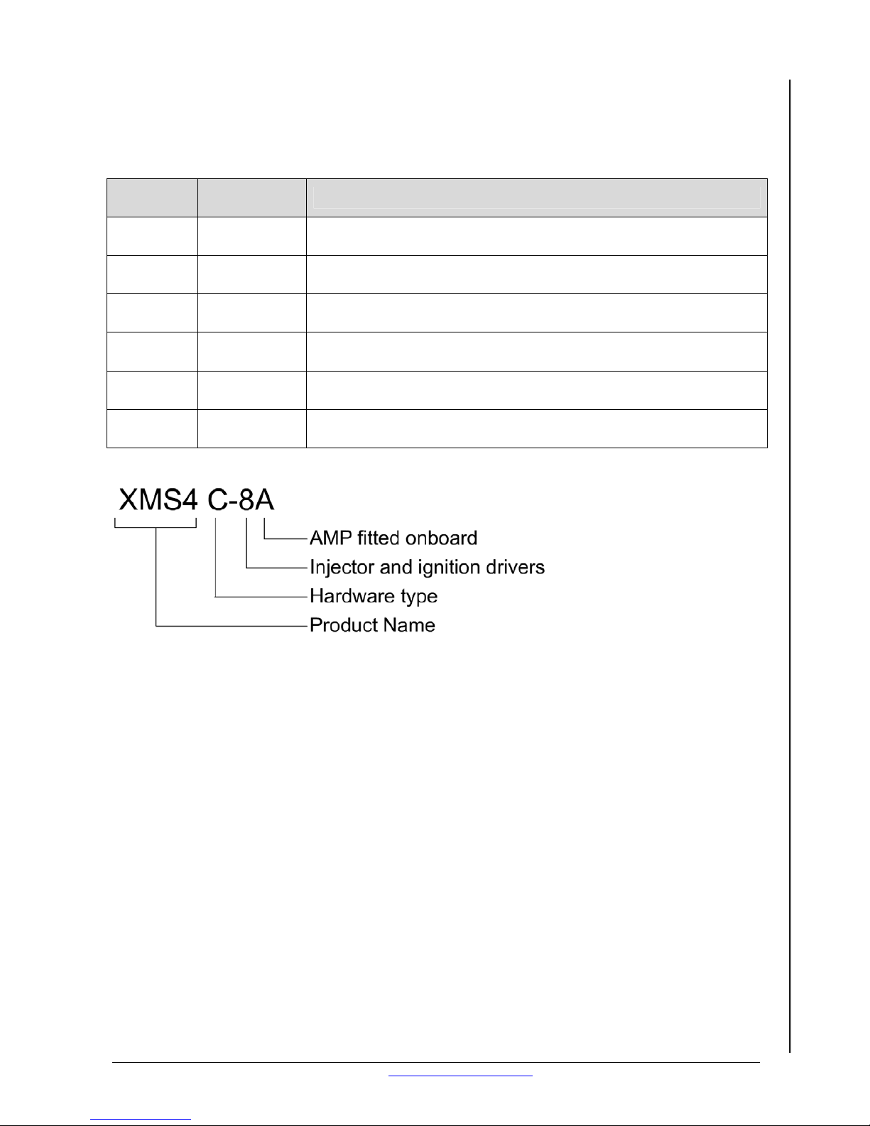
4. EXPLANATION OF XMS4 UNITS AVAILABLE
There are 6 different versions of the XMS4 unit availab le, and in this section we explain each
version available.
Hardware
Type
Part
Number
Details
A XMS4A-2A
2 Injection and Ignition Outputs, 4 Cylinder Batch Injection with
installed AMP sensor
A XMS4A-4A
4 Injection and Ignition Outputs, 4 Cylinder Sequential Injection.
4 Set points with installed AMP sensor.
B XMS4B-4A
4 Injection and Ignition Outputs, Wideband lambda controller. 4
Set points, with installed AMP sensor.
B XMS4B-8A
8 Injection and Ignition Outputs, Wideband lambda controller. 4
Set points, with installed AMP sensor.
C XMS4C-4A
4 Injection and Ignition Outputs, ETC, Wideband lambda
Controller. 8 Set points, with installed AMP sensor.
C XMS4C-8A
8 Injection and Ignition Outputs, ETC, Wideband lambda
Controller. 8 Set points, with installed AMP sensor.
Page 7

LETRIPP II XMS4A DIY MANUAL V2.1 www.perfectpower.com 3
PERFECT POWER XMS4A – Engine Management System DIY MANUAL V2.1
5. TECHNICAL DETAILS
The following features are that of an XMS4A.
5.1 FUEL INJECTION
• 3-Ampere injector drives : 2, 4
• Injection : Batch, Sequential
• Injector trimming : Yes
• Main map sites : 384
• Manifold pressure map sites : 24
• Engine temperature map sites : 24
• Air Temperature map sites : 24
• Max duty cycle : 100%
• Peak and Hold : No
• Injection length resolution : 0.01Ms
Total injection length is calculated as follows:
+ Main map entry
+ Air temperature entry
+ Engine temperature entry
+ Acceleration enrichment
+ AFR Short term loop adjustment
+ AFR Long term trim
+ Manifold pressure entry
+ Fuel range
Other fuel components:
+ Priming
+ Idle control
+ Set point control Soft/Hard fuel cut
5.2
IGNITION
Cylinders : 2, 3, 4, 6, 8
Ignition : Sequential: 2, 3, 4 Cylinders
Ignition outputs : 2, 4, 8
Direct drive : NO
Output polarity : Positive
Main map sites : 384
Manifold pressure map sites : 24
Engine temperature map sites : 24
Air temperature map sites : 24
Dwell length map sites : 24
Total ignition angle is calculated as follows:
+- Main map entry
+- Manifold pressure
+- Engine temperature entry
+- Air temperature entry
Other ignition components:
Launch control retard
Dwell
Page 8

LETRIPP II XMS4A DIY MANUAL V2.1 www.perfectpower.com 4
PERFECT POWER XMS4A – Engine Management System DIY MANUAL V2.1
5.3 ACCELERATION ENRICHMENT
Acceleration RPM Enrichment map sites: 24
Acceleration Air Temperature enrichment map sites: 24
Acceleration initial injection map sites: 24
5.4 INJECTOR/ENGINE PRIMING
Prime Engine temperature sites: 24
5.5 TRIGGER INPUTS
Balanced CRANK input YES
Balanced CAM input YES
Triggers on logic signal YES
User selectable CRANK polarity YES
User selectable CRANK trigger level YES
User selectable CAM trigger level YES
CAM on/off option YES
5.6 BOOST CONTROL
For Turbo waste gate control YES
PWM bleed Air temp. map sites 24
PWM sites for cruising 24
PWM sites for full power 24
Target boost map sites 24
PID loop gain YES
5.7 PRIME (FUEL)
24 Map sites accessed by the engine temperature, allow extra fuel during starting.
5.8 IDLE CONTROL
Target RPM map sites via temperature 16
For 2 wire idle motors YES
PID control YES
Integration time adjust YES
Loop gain adjust YES
5.9 SETPOINT CONTROL
Number of set-point functions 16
Number of assigned relay outputs 4
Output drives 0.5A
High/Low limit setting YES
Soft fuel limit YES
Hard fuel cut YES
“OR” function YES
“AND” function YES
Map switching YES
Output short circuit protection YES
Over-temperature protection YES
Page 9

LETRIPP II XMS4A DIY MANUAL V2.1 www.perfectpower.com 5
PERFECT POWER XMS4A – Engine Management System DIY MANUAL V2.1
6. FEATURE EXPLANATION
6.1 LAUNCH CONTROL
The Launch Control is for turbo cars where “spooling up” of the turbo is required on th e start
line. It is an extra switch input. The Launch Control is affected and works in the following way:
Proportional retard above a settable launch RPM limit. When the clutch is depressed (pushing
a switch) the ignition is retarded when a specified RPM is exceeded and advanced back to
normal when the clutch is released.
The Launch Control feature can also be used for “Flat-foot-shifting” in non-turbocharged
engines. This restricts the RPM to a specified level while the clutch is pressed and the
accelerator is pressed down.
6.2 EXTERNAL SUPPLY TO SENSORS
A separate +5 Volt output (pin 9 of 22) is available to power manifold pressure and TPS
sensors.
6.3 MAPS A / B
The XMS4A has two complete maps for all tuning data. Maps can be switched while driving.
The two maps can hold different tuning for weather, fuel grade or performance requirements.
The maps can be switched from a manual input, or automatically via the SETPOINT procedure
in the LetRipp Software.
6.4 CALIBRATION
All inputs can be calibrated to suit your existing sensors of your engine. Calibration is
performed for two reasons:
A) So that the XMS4A interprets the sensor readings correctly.
B) So that the Tuner (you) can read the data in engineering units (Bar/PSI,
Fahrenheit/Degree C, other).
6.5 FUEL INJECTION MAP
This map controls the fuel injection. The amount of fuel injected can be mapped on 384 sites
(main map) and the output of the three possible side maps can modify the main map value.
The entry is in counts, 100 counts = 1.00mS.
6.6 IGNITION MAP
This map controls the ignition. The ignition angle in degrees is from the 384 main map sites
and is further modified in the possible three side tables of 24 map sites each.
6.7 COMPENSATION MAP
This map contains various items:
• Acceleration enrichment
• Dwell time specification
• Priming
• Idle target control
Page 10

LETRIPP II XMS4A DIY MANUAL V2.1 www.perfectpower.com 6
PERFECT POWER XMS4A – Engine Management System DIY MANUAL V2.1
6.8 BOOST CONTROL
Boost Control is for turbo installations where the boost must be controlled:
• To avoid knocking on an engine, OR
• To avoid damaging a motor that is not designed for boost above a certain pressure, OR
• When the boost is increased at high RPM.
The boost level can be specified for each of the possible 24-RPM map sites. The XMS4A will
operate a “bleed” valve with the specified PWM values. The BOOST control loop can be
operated as an “open” loop by setting the required bleed PWM or as a “closed” loop PID
controller with target and gain adjustment.
NOTE: DO NOT use a solenoid with less than 13 ohm.
6.9 SETPOINT
The XMS4A has 4 set point outputs, which can be activated from 16 different signal sources.
This is for the implementation of fan control, gearshift lights, RP M limits, soft fuel cut and all
other small jobs around the engine and cockpit. All functions can be combined in a logical
AND/OR fashion, and polarity selection is possible.
6.10 MAXIMUM RECORDINGS
The units recorded are:
• Max RPM
• Max Engine temperature
• Max Air temperature
• Max Manifold pressure (AMP)
The maximum recordings can be retrieved and cleared by using a computer only.
6.11 ONBOARD LOGGING (COMING SOON)
All units have a very large memory for logging 64000 data points. This converts to:
• 5 Data channels, 12800 recordings OR 8 Data channels, 8000 recordings.
The amount of channels can be stipulated. The recording frequency ranges from:
• 200 records per second, 5ms TO 1 record per second, 1000ms
This means that 5 channel data can be recorded for 64 seconds at 5ms intervals, or for 213
minutes at 1 second intervals.
More to come later!
6.12 COMMUNICATION CONNECTION
All variations in the XMS4A product range have a USB 2.0 communication connector. It is best
to use the supplied cable to connect the XMS4A unit to your computer. If any communication
problems are encountered, (e.g. the PC hangs and must be restarted), then a “FERRITE”
interference eliminator must be used on the cable!
It is critical to follow the exact procedures for installing the USB drivers in the order indicat ed
in the Auto start on the CD supplied with the kit.
Page 11

LETRIPP II XMS4A DIY MANUAL V2.1 www.perfectpower.com 7
PERFECT POWER XMS4A – Engine Management System DIY MANUAL V2.1
6.13 USB DRIVERS SETUP
You will need to follow the step-by-step procedu re to load the Windows Tuning Software and
USB Drivers, in order for the unit to function correctly. The USB Drivers and Software need to
be installed in a specific order. You must refer to the “LetRipp Software Manual” to follow
the correct procedure.
Once the software and USB drivers have been correctly install ed, the unit will operate when
connected to the USB port via the USB cable. Thus the Computer will supply power to the unit.
Although all functions will work, the unit will not power external sensors.
NOTE: DO NOT ATTEMPT TO OPERATE THE XMS4A UNLESS THE USB INSTALLATION
PROCEDURE HAS BEEN FOLLOWED. FAILURE TO DO SO WILL RESULT IN THE NONOPERATION OF THE UNIT AND A LOT OF GRIEF TO CORRECT IT!
7. COMPUTER REQUIREMENTS
Intel 486 or higher, WINDOWS XP, USB Connection. At present, the LetRipp Software is NOT
Windows Vista compatible.
Page 12
LETRIPP II XMS4A DIY MANUAL V2.1 www.perfectpower.com 8
PERFECT POWER XMS4A – Engine Management System DIY MANUAL V2.1
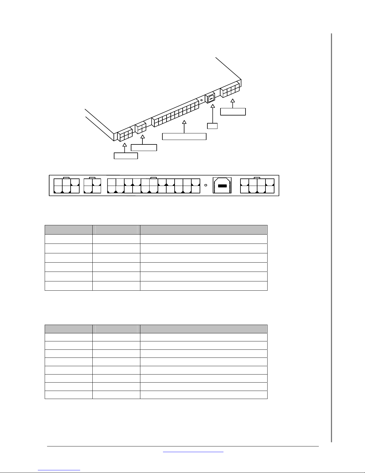
8. PIN OUTS OF XMS4A UNIT
8.1 XMS4A PIN-OUT TABLE
8.1.1
XMS4A IGNITION PIN-OUT CONNECTOR (6 PIN)
Pin Signal Description
1 GND Ground, chassis
2 IGN#1 #1 Ignition pulse output, positive
3 N/C N/C
4 IGN#2 #2 Ignition pulse output, positive
5 IGN#3 #3 Ignition pulse output, positive
6 IGN#4 #4 Ignition pulse output, positive
NOTE: The XMS4A-2A has ignition outputs 1 and 2
8.1.2 XMS 4A INJECTION PIN-OUT CONNECTOR (8 PIN)
Pin Signal Description
1 N/C N/C
2 INJ#1 Injector #1 output, switched to ground
3 INJ#3 Injector #3 output, switched to ground
4 GND Power Ground, Chassis
5 N/C N/C
6 INJ#2 Injector #2 output, switched to ground
7 INJ#4 Injector #4 output, switched to ground
8 GND Power Ground, Chassis
NOTE: The XMS4A-2A only has injector outputs 1 and 2
5
12
3
4
61011
12
978
13141516171819202122
5
12
3
4
678
5
12
3
4
6
12
3
4
XMS 4 A
Ignition
Main Connector
Auxiliary
PC
Injection
Page 13

LETRIPP II XMS4A DIY MANUAL V2.1 www.perfectpower.com 9
PERFECT POWER XMS4A – Engine Management System DIY MANUAL V2.1
8.1.3 XMS 4A AUXILIARY CONNECTOR (4 PIN)
Pin Signal Description
1 W1 Wire #1 output, switched to ground
2 W2 Wire #2 output, switched to ground
3 W3 Wire #3output, switched to ground
4 W4 Wire #4 output, switched to ground
8.1.4 XMS 4A MAIN CONNECTOR (22 PIN)
Pin Signal Description
1 MAP SW Map Switch Input, Open=high=A
2 CB 1 -
3 GND Signal Ground
4 CB 2 -
5 Rev Counter Rev counter driver
6 AMPIN 0-5V input signal
7 TPSIN 0-5V input signal
8 N/C Not used
9 +5volts EXT +5, 0.1A Output for TPS and AMP
10 +5volt pull up
11 GND
12 N/C Not used
13 Cb 1 +
14 GND
15 Cb 2 +
16 N/C Not used
17 AIRT IN 0-5V input, internal pullup 2k2 to +5
18 ENGT IN 0-5V input, internal pullup 2k2 to +5
19 N/C Not used
20 Launch Switch SWITCH input, normal high (open)
21 +5volt pull up
22 + SUPPLY Switched Battery Supply
Refer to section 33
and 34 for a basic wiring diagram of the XMS4A-2A and the XMS4A-4A.
Please note: The diagrams serve only as a guide to assist with the installation.
Page 14
LETRIPP II XMS4A DIY MANUAL V2.1 www.perfectpower.com 10
PERFECT POWER XMS4A – Engine Management System DIY MANUAL V2.1
9. ASSESSING YOUR CAR’S FUEL SYSTEM
If your car is fuel injected already you can skip this section and move onto section 9. If it is
not fuel injected, then you really need to go through this section to see in what state your
car’s fuel delivery system is. We will provide information on how to get the fuel system ready
for your fuel-injected engine.
9.1 IS YOUR CAR READY FOR FUEL INJECTION?
The first thing you will need to check is the fuel pump and establish whether it is a high or
low-pressure pump. This can be tricky and potentially dangerous so we only recommend one
way: using a fuel pressure gauge. If you don’t have one please get one. With the fuel gauge
connected to the pressure side of the fuel pump and the pump running you should get the
following:
Low pressure pump = 0–0, 5 bar (0–7psi)
High pressure pump = 2–4 bar (29–58psi)
If you get the 2–4 bar reading you can skip the next section, if not then you really need to
read on about how to fix this problem.
NOTE: That if the engine is turbo charged the fuel pressure must be 2, 5 bar plus the
maximum boost required e.g.: 2, 5 bar plus 0.6 bar boost should equal 3.1 bar fuel
pressure under boosted conditions.
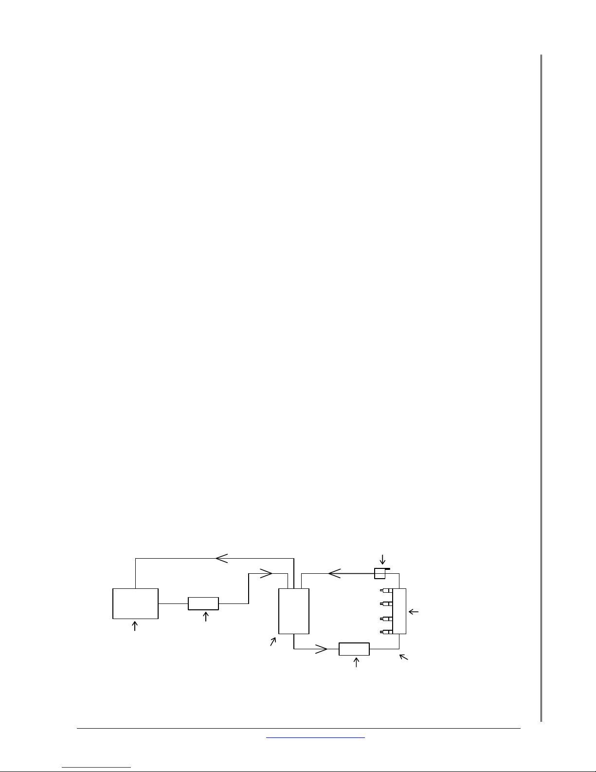
9.2 HOW TO MAKE YOUR CAR READY FOR FUEL INJECTION
Two fuel pumps are needed for the whole system to work. One from the fuel tank supplying a
surge tank, this is a low-pressure pump. This pump must be able to supply enough fuel to
keep the surge tank full at all times. A high pressure fuel pump to supply the fuel injectors.
Your engine must have fuel injectors - check Section 12.5 for more info. For details on the fuel
pump wiring see Section 18.2. More information on the setup of the au xiliari es can be found in
Section 23.
New fuel lines if needed can be made out of steel, copper or aluminum tubing. Rubber hoses
must be high pressure rated for pressures higher than 6 bar. Please ensure that you get
rubber hose that is also rated for fuel/gasoline. Always ensure that the fuel lines are securely
fastened to the chassis and engine.
Fuel pressure regulators vary in pressure and some are even adjustable. Ideally the fuel
pressure should be 2 to 2.7 bar at idle. Full throttle pressure on normally aspirated engines
should be 2.3 to 3.0 bar. On boosted engines the fuel pressure should be 2.5 bar plus the
boost.
Figure 1. Fuel System Layout
Fuel Tank
Low pressure
fuel pump
Surge Tank
High pressure
fuel pump
High pressure
fuel line
Fuel rail
and injectors
Fuel pressure
regulator
Fuel return
Page 15
LETRIPP II XMS4A DIY MANUAL V2.1 www.perfectpower.com 11
PERFECT POWER XMS4A – Engine Management System DIY MANUAL V2.1
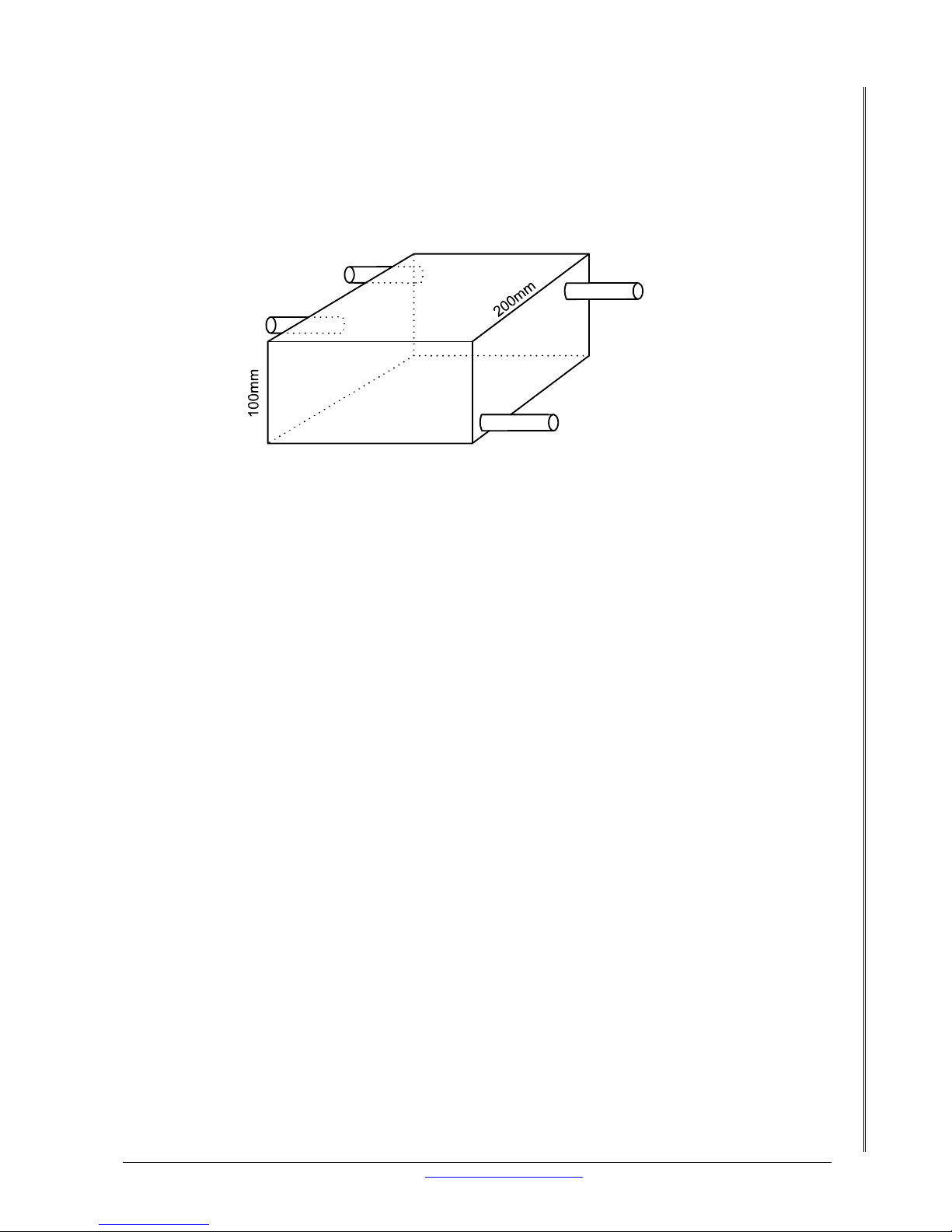
Unused fuel from the engine is returned through the regulator back to the surge tank, then
he surge tank should always be mounted higher than the high-pressure fuel pump. The
back to the fuel tank.
T
purpose of the surge tank is to ensure that the fuel line is not interrupted by air under high
speed cornering or under acceleration. The high-pressure pump must be fed by gravity. The
high-pressure pump must have a larger inlet supply than the return fuel line. See drawing
“enlarged view of surge tank” below.
Feed to high
pressure pump
Supply from low
pressure pump
Return to tank
Return from
fuel rail
200mm
10mm ID
8mm ID
8mm ID
8mm ID
Figure 2. Enlarged view of surge tank
afety: The fuel pump relay must be connected to the XMS4A
e
heck for leaks, if any fix them before moving on to anything else.
.3 CONCLUSION
ou have diagnosed your fuel system as to whether it is suitable for fuel injection. At this point
0. ASSESSING YOUR ENGINE
he engine will need to be assessed to determine if it has a compatible trigger wheel, cam
0.1 COMPATIBLE TRIGGER WHEEL
he XMS4A has a set of trigger patterns that it can work with, these are:
0 – 2
r higher)
S
The fuel pump must switch off when the engine stalls
Never connect the fuel pump to the key switch
Fuel lines must be securely fastened to the chassis
Rubber fuel lines must be rated for high fuel pressur
C
9
Y
you should have a fuel pressure of 2, 5 – 4 bar at the injectors. No fuel leaks and all fuel
piping nicely tucked away and securely fastened. The fuel pump is controlled by the XMS4A,
see section 18.2 for details on the wiring.
1
T
sensor (for sequential injection/ignition), typical sensors (used for compensation), injector
resistance and that it has the basics before we even try starting it.
1
T
6
36 – 2 (Firmware 25 o
36 – 1
24 + 1
24 + 2
Page 16

LETRIPP II XMS4A DIY MANUAL V2.1 www.perfectpower.com 12
PERFECT POWER XMS4A – Engine Management System DIY MANUAL V2.1
Which one does your engine have?
If your engine has a compatible trigger wheel and a pickup sensor fitted go onto section 9.2.
The best way to find out is to consult the engine manufacturer. You could also ask your local
garage if they know what trigger wheel your engine has on it. If you don’t know or are unable
to find out what trigger wheel (if any) is on the engine then you can fit a compatible wheel and
let the question rest. We recommend using a 60 –2 tooth wheel. This trigger wheel has 58
teeth and 2 missing teeth. It should be called 58 – 2 but the industry norm is 60 – 2. Ok now,
this trigger wheel must be connected to the crankshaft somehow. The normal place is on the
crankshaft pulley. See section 12.3 on how to install the compatible wheel.
10.2 CAMSHAFT SENSOR
This sensor reads off of a single tooth wheel on the camshaft. This signal repeats every 2
revolutions of the crankshaft. This signal is necessary for sequential ignition and injection. If
your engine does not have a cam sensor but you want sequential ignition and injection then
get an engine that has a cam sensor. Do not try to fit your own cam sensor.
10.3 HOW TO INSTALL A COMPATIBLE WHEEL AND PICKUP SENSOR
NOTE:
If you are unable to weld or fabricate metal, rather get a machine shop to do
this part of the work for you.
First you need to get the engine onto TDC. Most engines have timing marks on the crank
pulley and on the surrounding covers. If your engine has marks then simply align the marks
so that the crank pulley mark and the 0 deg mark line up. If your engine has no timing marks
you will need to make some of your own. Follow these steps to make your ow n timing marks
on your engine:
• Locate number 1 spark plug (it is the one closest to the cam belt or cam chain)
• Take number 1 spark plug out
• Use a long screwdriver to touch the top of the piston through the spark plug hole
• Turn the engine very slowly by hand (you can use a spanner or ratchet)
• Observe that the screwdriver moves up and down as the engine is turned
• When the screwdriver is at it’s highest point, TDC is reached
• Use a white marker to make your own timing marks on the crank pulley and
surrounding covers. These marks should be in a place that is easy to see as you will be
using them again in section 26
Crank pulley
Engine on TDC
TDC
0
Engine rotation
Figure 3. Crank Pulley
Page 17
LETRIPP II XMS4A DIY MANUAL V2.1 www.perfectpower.com 13
PERFECT POWER XMS4A – Engine Management System DIY MANUAL V2.1
With the engine on TDC (top dead center) it is time to see wh ere the pickup sensor will be
mounted. Choose a place that is easy to access and will not get in the way of an y pulley belts.
The pickup sensor must be mounted so that it is perpendicular to the trigger wheel. Once a
suitable location has been decided upon the crank pulley must be removed.
Note:
You can get a 60 – 2-tooth wheel, which has the two teeth missing, or you can get a
wheel, which has 60 teeth with no missing teeth. Care must be taken if you are fitting the 60
– 2 tooth wheel with the missing teeth as the gap in the teeth must be in a specific location in
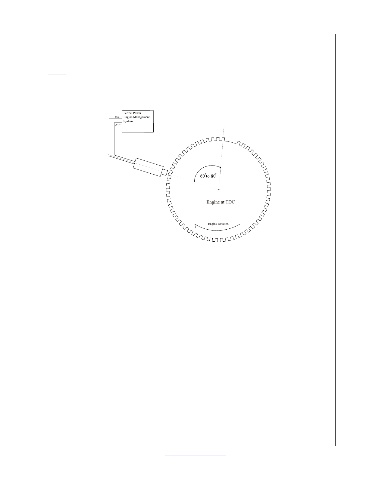
relation to the pickup sensor and TDC. At TDC the gap must be 50 – 80 degrees passed the
sensor in the direction of engine rotation. See picture below.
Magnetic
Sensor
60 - 2 Tooth Whe el Setup
with the engine on TDC
Figure 4. 60 – 2 Tooth Wheel Setup
The 60 – 2 tooth wheel must be secured to the crank pulley as central as possible. We
recommend that once the trigger wheel is secured to the pulley; get a machine shop to skim
the trigger wheel’s teeth in a lathe. This will ensure that the 60–2-tooth wheel runs true and
that the XMS4A will get a nice, even signal. Fit the crank pulley back onto the crank. Make a
bracket for the pickup sensor and mount the sensor and bracket in place. The gap between
the sensor and the pickup wheel should be 0.8mm. If you have fitted a wheel with no missing
teeth you need to remove two teeth from the wheel. See Figure 4, above.
10.4 WHICH SENSORS ARE MISSING?
For the XMS4A to be an effective management system it requires certain sensors to give it
information on the changing engine conditions . The most common sens ors are listed in section
17. Should you need the following sensors, we (Perfect Power) can supply them.
• Engine temperature
• Air temperature
• AMP
10.5 INJECTOR RESISTANCE
The XMS4A has 2 amp injector drivers, each injector driver is capable of driving 1 x 10 ohm
injector or 2 x 20 ohm injectors. What injectors do you have? To find out you must measure
each injector’s resistance with an ohm meter (Multi Meter). 2 ohm injectors will be a problem
and you will need external injector drivers. We can supply external injector amplifiers that are
rated at 7 amps and 25 amps.
Page 18
LETRIPP II XMS4A DIY MANUAL V2.1 www.perfectpower.com 14
PERFECT POWER XMS4A – Engine Management System DIY MANUAL V2.1
10.6 MAKE SURE THE ENGINE HAS THE BASICS
There must be enough oil in the crankcase, check the dipstick. There must be water in the
radiator. The alternator belt must be properly adjusted so it wi ll not slip. The battery must be
fully charged.
10.7 CONCLUSION
You have a compatible trigger wheel on your engine. The injectors have been measured and
the XMS4A or an external amplifier will be driving them.
11. WHERE TO FIT YOUR XMS4A?
This is extremely important to read as you need to find a suitable location to mount your
XMS4A to avoid damage to the unit or vehicle. If you plan on installing your XMS4A where
there was an existing management system you should read this section too.
11.1 SUITABLE PLACES
The best place to mount the unit isn’t always the easiest. Usually best locations are as follows:
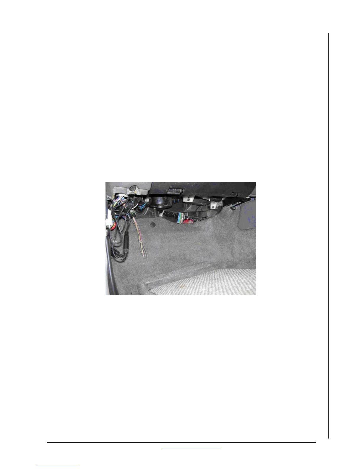
• Under the dashboard. There is normally enough space. It is free of moisture and
excessive heat.
Figure 5. Typical “under the dashboard” installation
• Center consol. It is also free of heat and moisture but may have space lim itations.
• Driver sidekick panel. Free from heat and moisture. Some vehicles have space
limitations.
• Passenger side front kick panel. Same as driver side but most vehicles have enough
open space to mount the XMS4A there.
• Under driver or passenger seat. Very good location. Free from heat and moisture. Lots
of space.
• Rain tray. This can be a good location provided that you r particular location in the rain
tray is waterproof. The XMS4A is not waterproof so it must be protected from moisture.
There are of course other locations and should you find one ask yourself three questions:
1. Is there enough space for my XMS4A to fit in there?
2. Is this going to be free from moisture at all times?
Page 19

LETRIPP II XMS4A DIY MANUAL V2.1 www.perfectpower.com 15
PERFECT POWER XMS4A – Engine Management System DIY MANUAL V2.1
3. Is the XMS4A going to remain well below 60 degrees Celsius?
If all 3 answers are YES, then fit your XMS4A there.
Mount your XMS4A firmly in place. The XMS4A should be mounted so that the casing is not
exposed to any stress. Note: The typical length of the XMS4A harness is 1, 5 meters long, so
consider this when choosing your location. Some people don’t mount the XMS4A but just tuck
it away. You can do this too but make sure that there is no stress on the wiring harness.
11.2 UNSUITABLE PLACES
• Anywhere in the engine bay. Why you say? The engine bay is a major heat generating
and heat-retaining cell. The XMS4A has been designed to be exposed to a maximum
temperature of 60 degrees Celsius. (140 degrees Fahrenheit). Under bonnet
temperatures exceed this limit and will cause the XMS4A t o fail. If your existin g engine
management system was mounted onto the engine DO NOT mount your XMS4A on top
of it.
• In the rain tray. This is potentially a bad location if it is not completely free from
moisture at ALL times. To test the location you can always fill a bu cket or use a hose
pipe and spray water on the rain tray with the bonnet closed. Test circumstance should
be with the bonnet closed as the car would normally be driven. If any moisture enters
your chosen location, disregard it and refer to section 10.1 for another possible
location.
• Away from heat generating devices, for example on top of the exhaust tunnel or
directly in front of the heater vents.
• Anywhere the XMS4A can get wet. Pretty simple to understand but if you know that
your car leaks water by the passenger side then don’t mount your XMS4A anywhere
near there.
• In the Boot. This is a great place for spare tires and speakers. I don’t recommend it
because the possibility of your XMS4A getting accidentally damaged by some heavy
piece of equipment is too high.
• Anywhere the XMS4A could be exposed to excessive vibration.
• Under front passengers feet. Some vehicles have a protective metal case under the
passenger’s feet. This case protects the existing engine management system. If your
vehicle does not have a protective case, don’t mount your XMS4A there.
11.3
CONCLUSION
You now have mounted your XMS4A in a suitable place where it will not come into harms way.
Now we need to do the same with the ignition amplifier.
12. WHERE TO FIT THE IGNITION AMPLIFIER?
This section is extremely important, as you need to find a suitable location to mount the
ignition amplifier to avoid damage to the unit or vehicle. The XMS4A and the ignition amplifier
must be fitted at least 1 meter apart.
12.1 SUITABLE PLACES
The best place to mount the unit isn’t always the easiest. Usually the best locations are as
follows:
Page 20

LETRIPP II XMS4A DIY MANUAL V2.1 www.perfectpower.com 16
PERFECT POWER XMS4A – Engine Management System DIY MANUAL V2.1
• Under the dashboard. There is normally enough space. It is free of moisture and
excessive heat.
• Center consol. It is also free of heat and moisture but may have space lim itations.
• Driver side kick panel. Free from heat and moisture. Some vehicles have space
limitations.
• Passenger side front kick panel. Same as driver side but most vehicles have enough
open space to mount the ignition amplifier.
• Under driver or passenger seat. Very good location. Free from heat and moisture. Lots
of space.
• Rain tray. This can be a good location provided that you r particular location in the rain
tray is waterproof.
There are of course other locations and should you find one ask yourself four questions before
fitting the ignition amplifier:
1. Is there enough space for the ignition amplifier to fit in there?
2. Is this going to be free from moisture at all times?
3. Is the ignition amplifier going to remain well below 60 degrees Celsius?
4. Is the ignition amplifier more than 1 meter from the XMS4A?
If all 4 answers are YES, then fit the ignition amplifier there.
12.2
UNSUITABLE PLACES
• Anywhere in the engine bay. Why you say? The engine bay is a major heat generating
and heat-retaining cell. Ignition amplifiers generate heat as they operate, any extra
heat can cause the amplifier to fail.
• In the rain tray. This is potentially a bad location if it is not completely free from
moisture at ALL times.
• Away from heat generating devices. For example on top of the exhaust tunnel or
directly in front of the heater vents.
• Anywhere the ignition amplifier can get wet.
12.3 CONCLUSION
You now have mounted your ignition amplif ier in a suitable place where it will not come into
any harms way.
13. SCREENED CABLE
This section is about a type of cable that provides resistance to potential noise. Why we use
these shielded wires and what gains we get out of it? If you are having no RPM or interference
problems you can move onto section 16.
Page 21
LETRIPP II XMS4A DIY MANUAL V2.1 www.perfectpower.com 17
PERFECT POWER XMS4A – Engine Management System DIY MANUAL V2.1
13.1 WHAT IS A SCREENED CABLE?
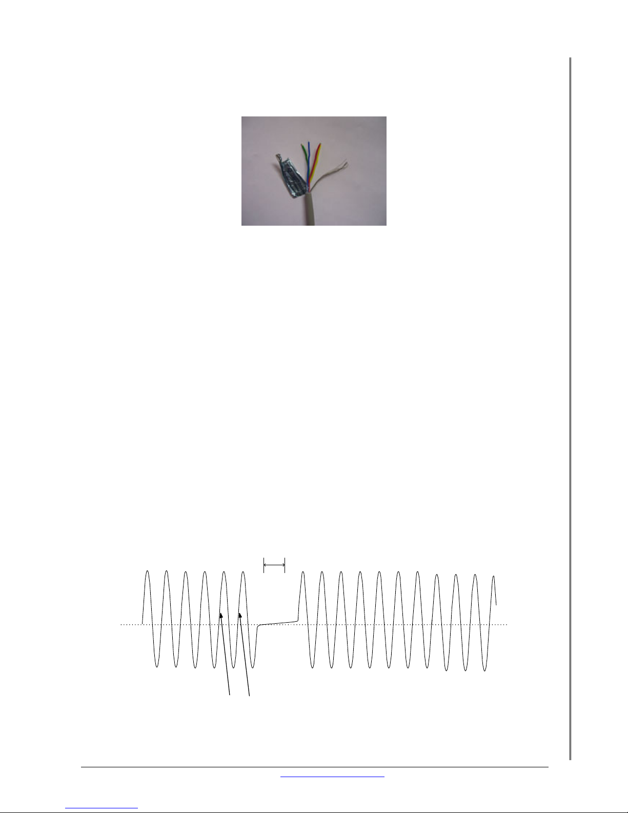
Screened cable is a bunch of wires sometimes 2 sometimes 14, the number of wires isn’t the
point. All the wires are surrounded by another wire in a braided fashion or by a conductive foil.
Figure 6. 4 Wire plus screen foil
13.2 WHY SHOULD I USE A SCREENED CABLE?
The XMS4A uses the incoming rpm signal to calculate everything. If this signal is interrupted
or noisy you can have lots of problems. The screened cable has a shield, which acts as a
faraday cage; this reduces electrical noise from affecting our rpm signal. Tip: Only ground the
screen wire at one end.
13.3 WHAT SHOULD YOU USE A SCREENED CABLE ON?
Anything you would like to protect from interference. In your case the crank and cam inputs.
Crank inputs are: pins 2 and 13 of the 22 pin connector
Cam inputs are: pins 4 and 15 of the 22 pin connector
So if you have any thoughts about noise getting into your XMS4A I suggest that you use
screened cable on the crank and cam inputs.
14. CRANK SIGNALS - WHAT DO THEY LOOK LIKE?
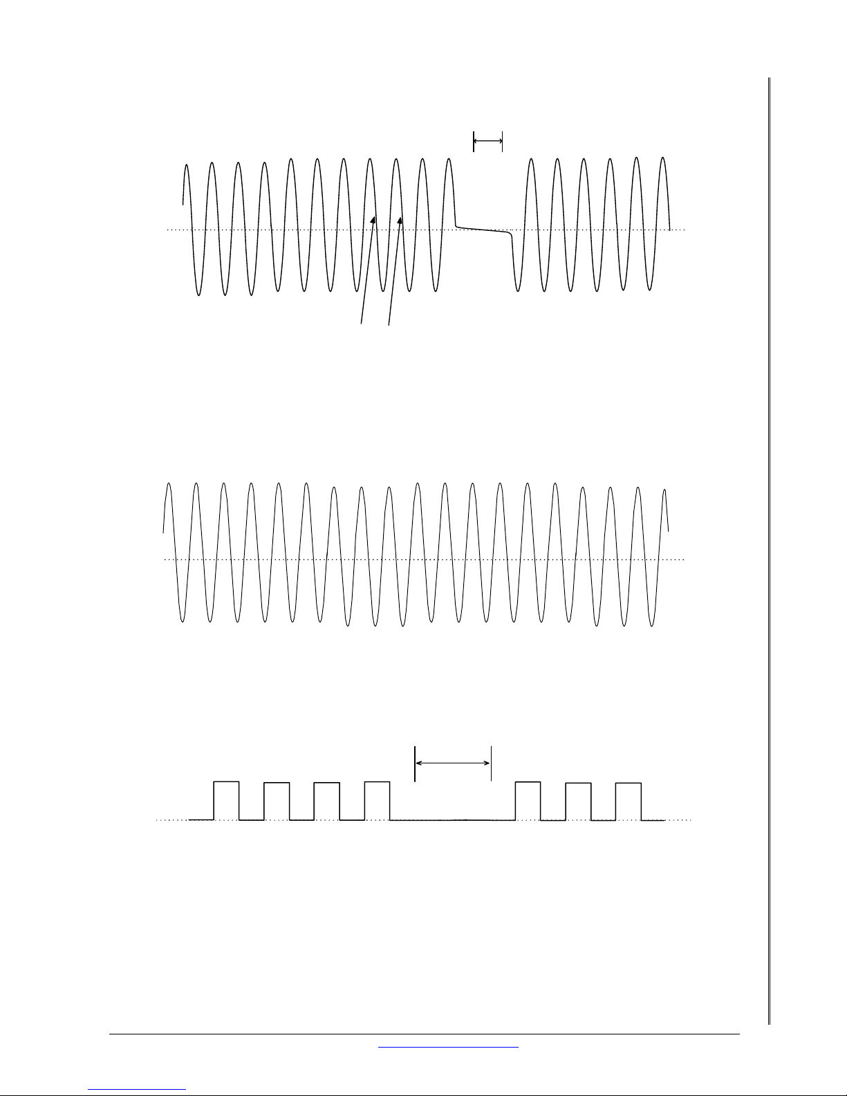
Using an oscilloscope the pattern of the crank pickup can be seen to look like the following
diagrams.
14.1 POSITIVE EDGE
Missing teeth
Positive crank edge
0
+
-
Page 22
LETRIPP II XMS4A DIY MANUAL V2.1 www.perfectpower.com 18
PERFECT POWER XMS4A – Engine Management System DIY MANUAL V2.1
14.2 NEGATIVE EDGE
Negative crank edge
Missing teeth
0
+
-
14.3 MAGNETIC
When the teeth of the trigger wheel passes in front of the sensor, a variation in the magnetic
field is created. This variation induces an alternating volt age (sinusoidal wave) in th e winding.
The amplitude and frequency of this signal is proportional to the rotational speed of the
engine.
Magnetic sensor signal
14.4 DIGITAL/HALL EFFECT
This type of signal is often referred to as a switch as it goes “on” and “off”.
0
Missing teeth
+
-
15. TYPICAL SENSORS USED AND HOW TO WIRE THEM
Descriptions of the most commonly used sensors and which of the wires on your XMS4A to
connect them to. Wiring information on amp, TPS, lambda, crank and cam sensors. If all your
sensors are wired up and working then skip this section.
Page 23
LETRIPP II XMS4A DIY MANUAL V2.1 www.perfectpower.com 19
PERFECT POWER XMS4A – Engine Management System DIY MANUAL V2.1
15.1 AMP
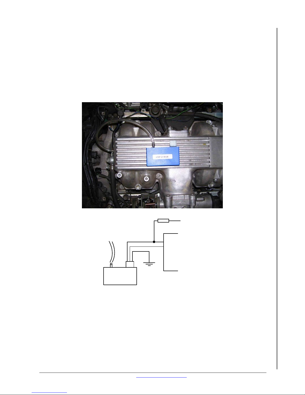
Absolute Manifold Pressure or Manifold Absolute Pressure (Map). In simple terms this sen sor is
used to determine the load on the engine. It converts vacuum/pressure into a voltage, which
the XMS4A uses to compensate for different conditions. See section 26 for more details. This
sensor is preferable to have. Some XMS4A’s have a built in amp sensor. Check section 4. The
amp sensor must cover your expected manifold pressure including boost.
An external amp sensor can be mounted in the engine bay on the firewall if your XMS4A
doesn’t have a built-in one. You can secure it with zip ties. Use durable vacuum hose from the
amp sensor to the inlet manifold. You need to give this Amp sensor vacuum so you will need
to find this on the inlet manifold after the throttle body . See picture below.
Perfect Power
2,5 Bar Amp
Sensor
XMS4
Black
Yello w
Black/Red
Pin 22 of 22 (+12 supply
Pin 6 of 22 (Amp input)
+12 volts switch
power
Fuse
Vacume line
< 10 Amps
Figure 7. Wiring of Perfect Power Amp Sensor
If you are using another make of map sensor, check with the manufacturer for wiring details.
Some use 5 volts and your XMS4A has a 5 Volt supply wire for this purpose. The 5 Volt output
is wire 21 of the 22 pin connector. As you can see Perfect Power’s Amp sensor uses 12 volts.
15.2 ENGINE TEMP
The engine temp sensor is used by the XMS4A to primarily adjust the fuel for cold start. The
engine temp sensor relays to the XMS4A the temperature of the engine (in volts) and the
XMS4A uses this information to compensate for different engine conditions. See section26. The
engine temp sensor is normally fitted to the engine head.
Page 24
LETRIPP II XMS4A DIY MANUAL V2.1 www.perfectpower.com 20
PERFECT POWER XMS4A – Engine Management System DIY MANUAL V2.1
XMS4
Pin 18 of 22 (Engine temp input)
Pin 14 of 22 (Ground)
Engine
temp
Wiring of Perfect Power
Engine temp sensor
Figure 8. Wiring of Perfect Power Engine Temp Sensor
If you are using another make of engine temp sensor, it must be of the NTC (negative
temperature coefficient) type.
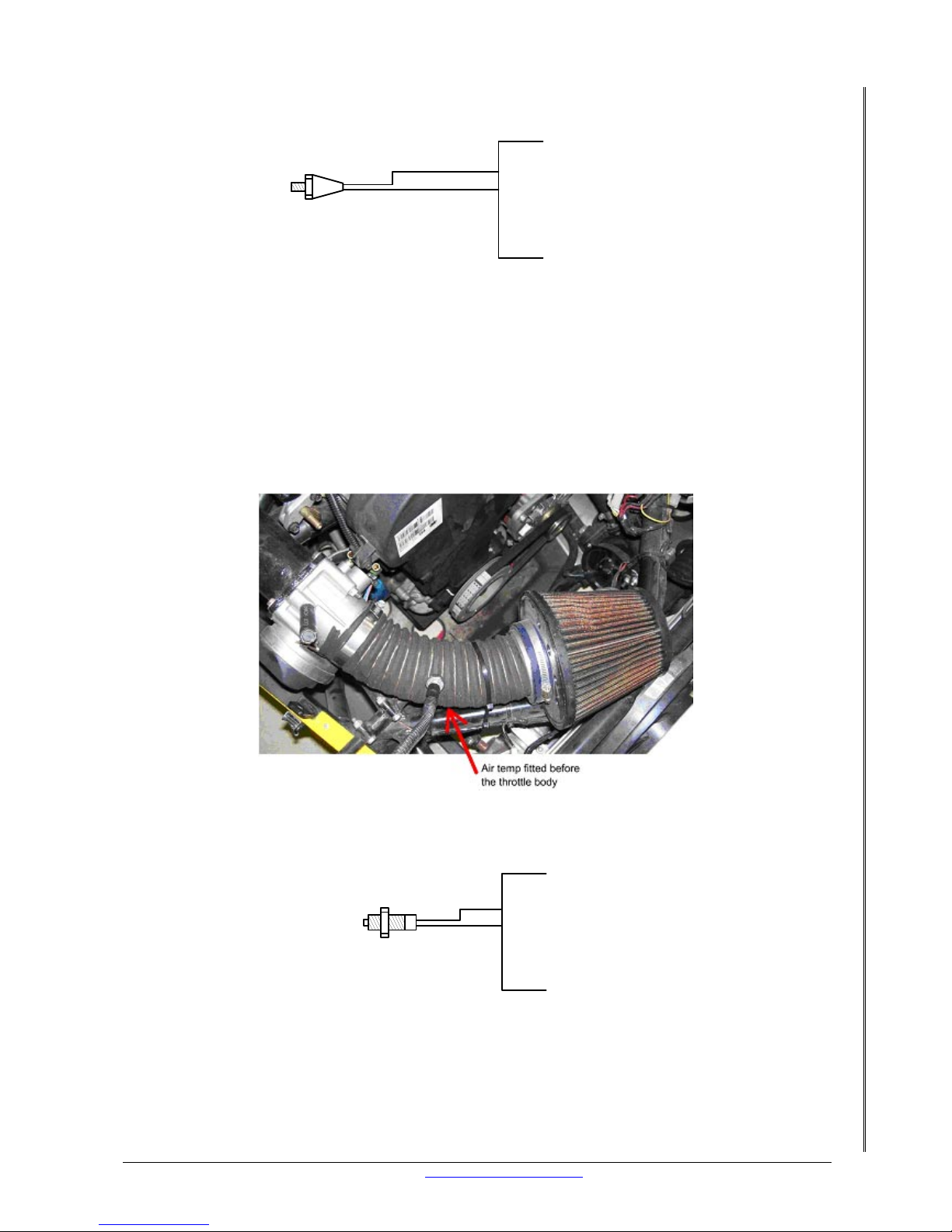
15.3 AIR TEMP
Air temperature is important on boosted engines as the air temperature is raised considerably.
The air temp sensor relays to the XMS4A the temperature of the intake air (in volts) and the
XMS4A uses this information to compensate for different engine conditions. See section 26.
The air temp sensor is normally fitted to the inlet pipe before the throttle body.
XMS4
Pin 17 of 22 (Air temp input)
Air
temp
Pin 14 of 22 (Ground)
Wiring of Perfect Power
Air temp sensor
Figure 9. Wiring of Perfect Power Air Temp Sensor
NOTE: If you are using another make of air temp sensor, it must be of the NTC type.
Page 25
LETRIPP II XMS4A DIY MANUAL V2.1 www.perfectpower.com 21
PERFECT POWER XMS4A – Engine Management System DIY MANUAL V2.1
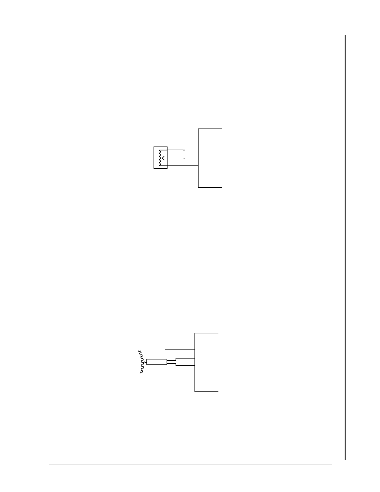
15.4 THROTTLE POSITION
This sensor detects the movement of the throttle butterfly. This in turn tells the XMS4A what
the driver is doing with his foot, accelerating for example. The XMS4A detects acceleration and
compensates for it. See section 25. This sensor requires some testing with an ohmmeter
before you wire it up. The TPS (Throttle Position Sensor) has three wires (ok some do have
more than 3) but only 3 are of use to us. There is a ground, +5 volts and the sweeper signal.
To find the +5 volt and ground use a Multimeter and measure the resistance between all of
the pins. The two pins with the highest resistance are the +5 and ground. Another way of
checking is the two pins that give a constant resistance the whole time the throttle is being
opened to WOT are the +5 volt and ground wires. The other wire will be the sweeper signal. If
you have electronic throttle control the accelerator pedal position signal must be used.
Pin 7 of 22 (TPS input)
Pin 11 of 22 (Ground)
XMS4
Pin 9 of 22 (5volt supply)
Throttle
Position
Sensor
Figure 10. Wiring of Throttle Position Sensor
WARNING
: Never assume that the tw o oute r pi ns are power and ground and that the
center pin is the signal.
If the TPS reading is in reverse as the throttle is pressed (right t o left) you can swap the +5
volt and ground around. Or, the XMS4A can swap this in the software. See the LetRipp
Software Guide.
15.5 CRANK ANGLE SENSOR
NOTE: This Section is IMPORTANT!!!!
The crank angle sensor reads the teeth of a toothed wheel that is mounted on the crankshaft
or on the crank pulley. The crank sensor converts each tooth into a signal. See section 16 for
details on the signals. The XMS4A uses this sensor for RP M readings, calculates the ignition
timing and the fueling. An important sensor you might say. See section 12.3 on how to setup
the crank sensor and a toothed wheel.
Pin 13 of 22 (+CB1 input)
XMS4
Pin 2 of 22 (-CB1 input)
Pin 11 of 22 (Ground)
Crank angle Sensor
( Magnetic )
Figure 11. Wiring of Magnetic
Page 26
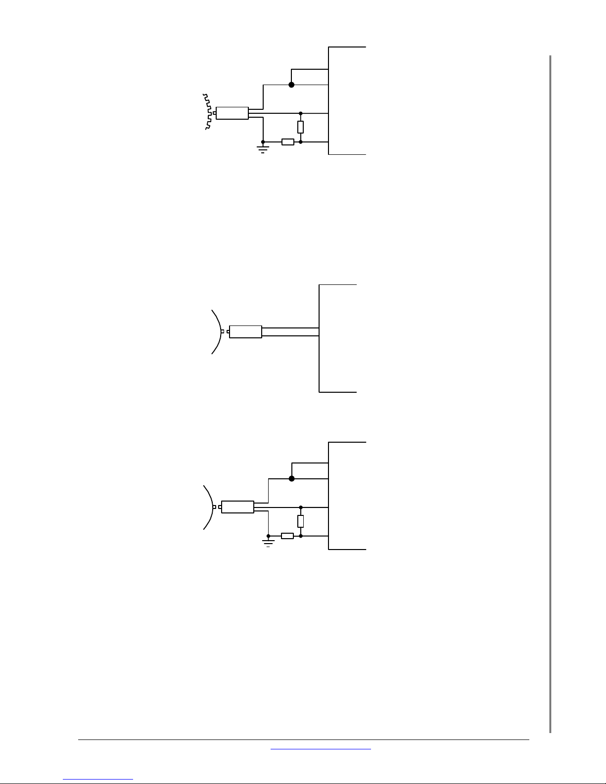
LETRIPP II XMS4A DIY MANUAL V2.1 www.perfectpower.com 22
PERFECT POWER XMS4A – Engine Management System DIY MANUAL V2.1
Pin 13 of 22 (+CB1 input)
XMS4
Pin 9 of 22 (5 volt supply)
2k2
2k2
Pin 2 of 22 (-CB1 input)
Pin 10 of 22 (5v pull up)
Crank angle Sensor
( Hall Effect )
Figure 12. Wiring of Hall Effect
If you have unstable RPM under cranking move the sensor closer to the pickup wheel. Set the
trigger level in system definition (Shift F2) to OFF if you have no RPM.
15.6 CAMSHAFT SENSOR
This sensor reads off the camshaft and it identifies cylinder no l. If you have a camshaft sensor
this is how you wire it.
Magnetic
Pin 15 of 22 (+CB2 input)
XMS4
Pin 4 of 22 (-CB2 input)
Cam Sensor
( Magnetic )
Hall effect
Pin 10 of 22 (5v pull up)
Pin 15 of 22 (+Cb2 input)
XMS4
Pin 9 of 22 (5volt supply)
2k2
2k2
Pin 4 of 22 (-CB2 input)
Cam Sensor
( Hall Effect )
15.7 CONCLUSION
You have all the sensors you need to use and they are wired up to your XMS4A. You know why
you need these sensors so let’s move onto devices driven by the XMS4A.
Page 27
LETRIPP II XMS4A DIY MANUAL V2.1 www.perfectpower.com 23
PERFECT POWER XMS4A – Engine Management System DIY MANUAL V2.1
16. TYPICAL DEVICES DRIVEN BY THE XMS4A
This section explains how to wire the devices used by the engine but driven by the XMS4A.
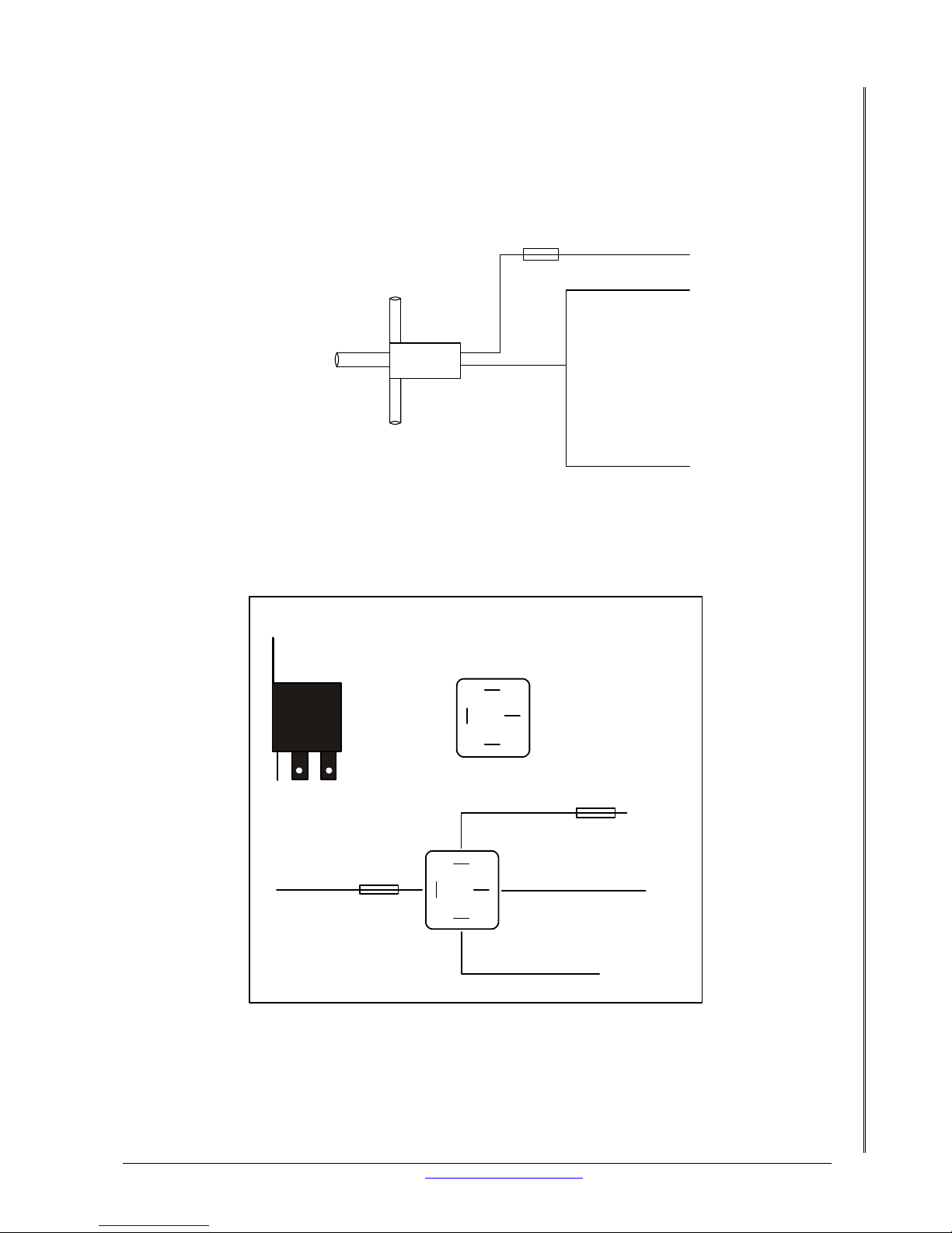
16.1 BOOST SOLENOID
This solenoid is used on turbo charged engines to regulate the boost electronically. Any
auxiliary output can be used provided there is one spare.
To manifold
To wastgate
To atmosphere
XMS4
Auxillary
connector
5 Amp
+12 Volts switch power
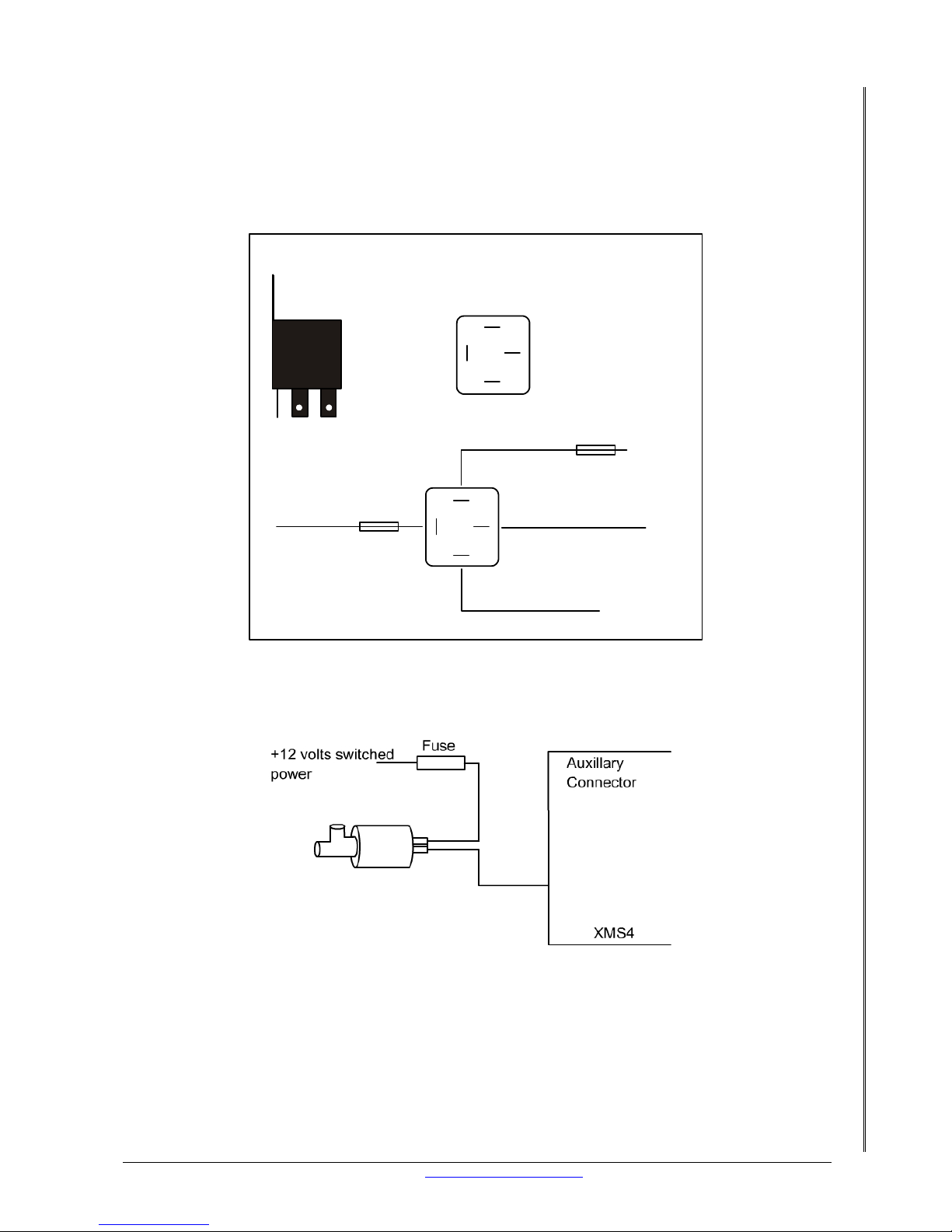
16.2 FUEL PUMP RELAY
For safety reasons the XMS4A must control the fuel pump relay. The XMS4A will switch the
fuel pump off if the RPM input stops. The fuel pump relay is connected to the XMS4A’s
auxiliary connector.
30
87
85
86
Side View
Bottom View
Pin 85 and 86 = Coil
Pin 30 and 87 = Relay Switch
30
87
85
86
+12 Volts Switch Power
Positiv e Battery
Device Power eg: Fuel pump
Fuse
Fuse
Example of a 4 Pin Relay
XMS4 auxillary output
Page 28
LETRIPP II XMS4A DIY MANUAL V2.1 www.perfectpower.com 24
PERFECT POWER XMS4A – Engine Management System DIY MANUAL V2.1
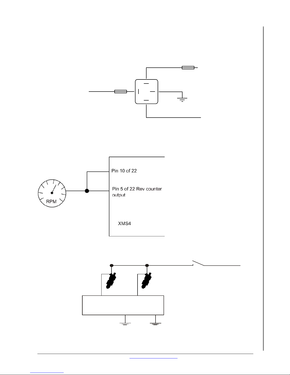
16.3 FAN RELAY
The cooling fan can be controlled by the XMS4A through a relay. The fan is programmed to
turn on at the desired engine temperature using the set points.
30
87
85
86
Side View
Bottom View
Pin 85 and 86 = Coil
Pin 30 and 87 = Relay Switch
30
87
85
86
+12 Volts Switch Power
Positiv e Battery
Device Power eg: Fan
Fuse
Fuse
Example of a 4 Pin Relay
XMS4 auxillary output
16.4 2 WIRE IDLE CONTROL MOTOR
The XMS4A can control a two wire idle motor.
Pin 3 of 4
Page 29
LETRIPP II XMS4A DIY MANUAL V2.1 www.perfectpower.com 25
PERFECT POWER XMS4A – Engine Management System DIY MANUAL V2.1
16.5 SHIFT LIGHTS
The XMS4A can turn light/s on at a specific RPM to warn the driver of the upcoming RPM limit.
The light/s are connected to a relay that the XMS4A controls via an auxiliary. The RPM at
which the XMS4A will engage the relay is programmed in the set points.
30
87
85
86
+12 Volts Switch Power
Positive Battery
Device Power eg: Shift light
Fuse
Fuse
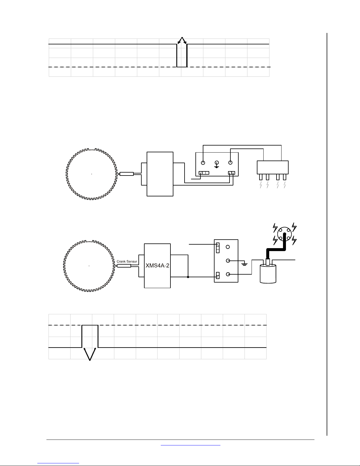
16.6 REV COUNTER
The XMS4A has a dedicated rev counter output on pin 5 of 22. This output is a square wave
and can operate most modern rev counters. Should your rev counter not operate correctly,
See Troubleshooting?
16.7 INJECTORS
+12
Key S wit ch
Max 3A
XMS 4A-2
Injector Connector
Pin 4 Pin 8
Conventional “NON - STEPPED”
Please refer to pinout data for details on your specific unit.
Pin 2
Pin 7
Page 30
LETRIPP II XMS4A DIY MANUAL V2.1 www.perfectpower.com 26
PERFECT POWER XMS4A – Engine Management System DIY MANUAL V2.1
XMS4
Injection output
Negitive signal
0
+
Injector open
time
16.8 IGNITION AMPLIFIERS
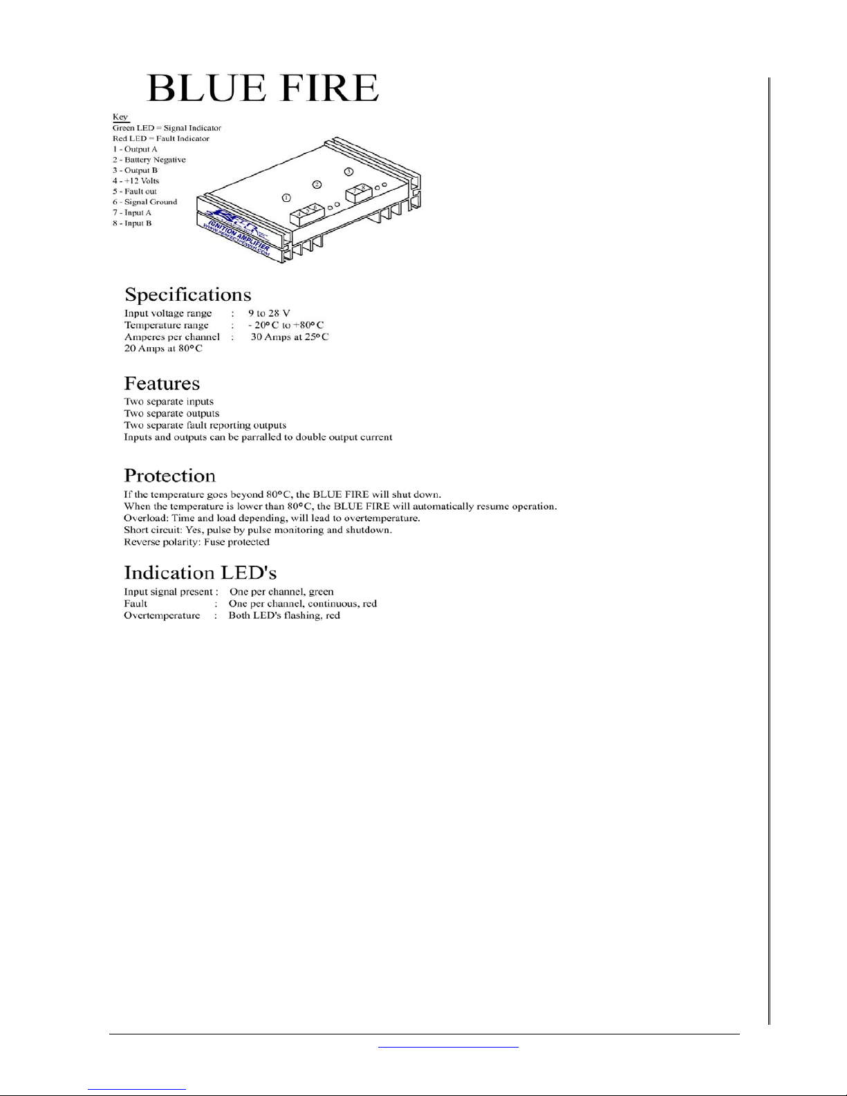
The XMS4A needs an ignition amplifier to drive the coil/s. There are many makes and models
of ignition amplifiers available. You will need to use the Perfect Power “Blue Fire” ignition
amplifier or any positive triggering ignition amplifier.
XMS4A-2
Cb1 +
Cb1 -
Blue Fire
+12 Volts
Coil Pack
Spark Plugs
Ig1 out
Ig2 out
Crank Sensor
Typical wiring of wasted spark
Typical wiring of a single coil for a distibutor
+12 volt
Blue Fire
-
+
+12 volt
Ig1 out
Ig2 out
CB1+
CB1-
Coil
0
+
XMS4
Igniton output
Positive signal
DWELL
Page 31
LETRIPP II XMS4A DIY MANUAL V2.1 www.perfectpower.com 27
PERFECT POWER XMS4A – Engine Management System DIY MANUAL V2.1
17. IDLE CONTROL – IN MORE DETAIL
This feature uses a two wire idle motor to compensate when extra load is applied to the
engine during idle conditions. The idle can also be adjusted as the engine temperature
changes.
17.1 TWO WIRE IDLE – SOFTWARE SETUP
The XMS4A unit can control a two wire idle motor. The wiring is done through an auxiliary
connector. See Section 16.4 for wiring details.
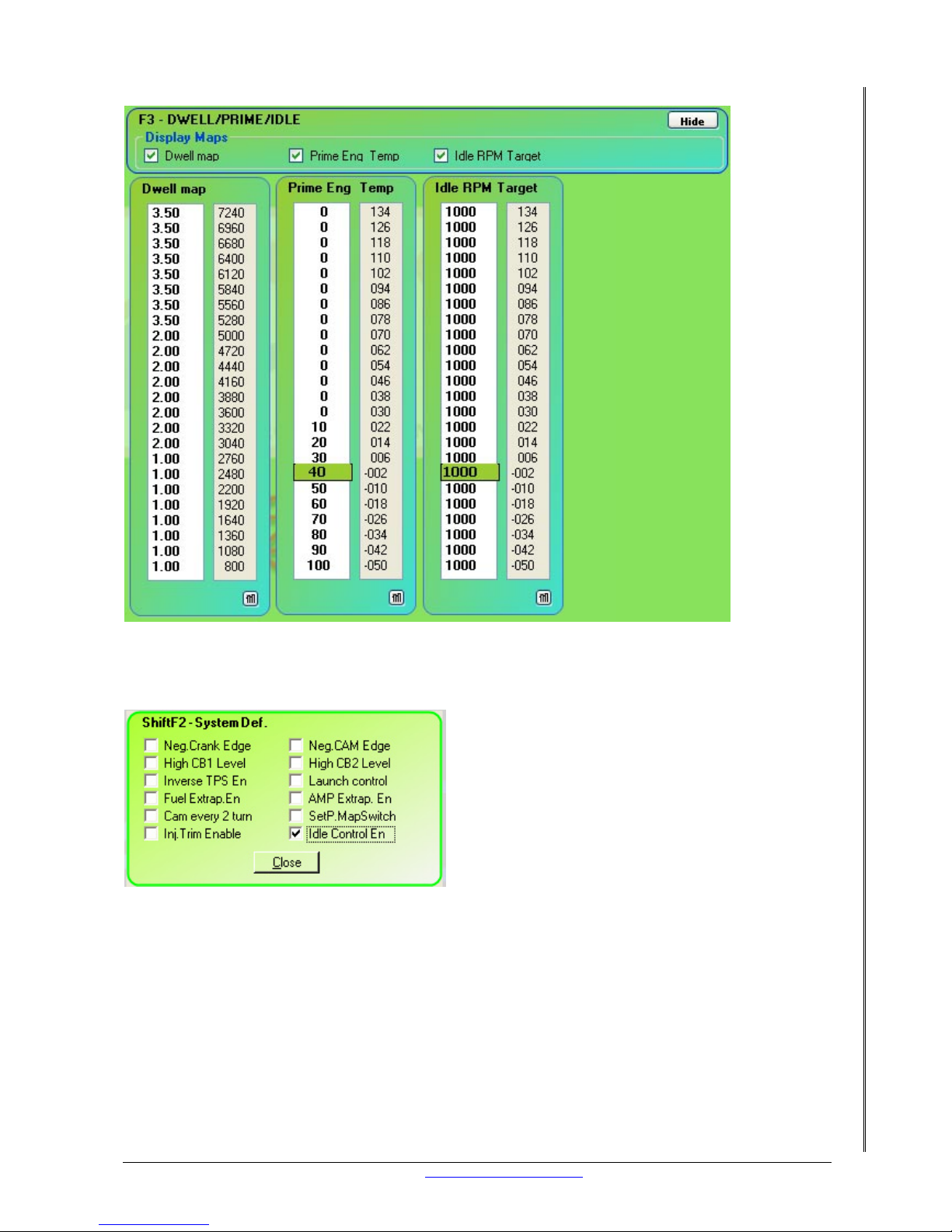
Set the idle in the LetRipp Software using the following maps:
Page 32
LETRIPP II XMS4A DIY MANUAL V2.1 www.perfectpower.com 28
PERFECT POWER XMS4A – Engine Management System DIY MANUAL V2.1
17.1.1 F3 – TWO WIRE IDLE FOR XMS4A
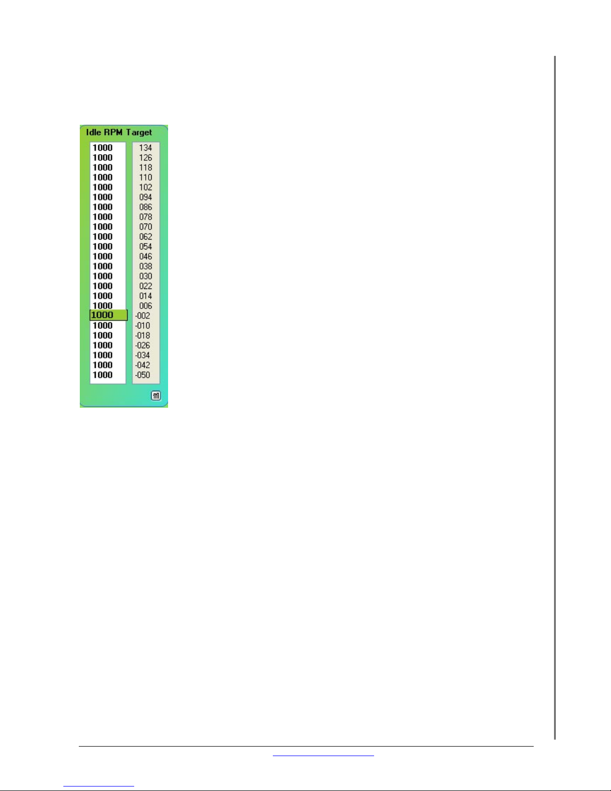
17.1.2 SHI FT F2 – SYSTE M DEF
Tick the “Idle Control En” check box.
Page 33
LETRIPP II XMS4A DIY MANUAL V2.1 www.perfectpower.com 29
PERFECT POWER XMS4A – Engine Management System DIY MANUAL V2.1
17.1.3 IDLE RPM TARGET
Set realistic idle targets for the range of engine temperature. A cold engine prefers to idle
higher than a hot engine.
17.1.4 SHIFT/F11 – 2WIRE IDLE
To setup the two wire idle the following targets need to be programmed:
• Idle Minimum: This is the minimum idle PWM
• Idle Maximum: This is the maximum idle PWM
• Idle Kick Open %: This is the amount that the idle motor will “kick” open
• Idle Kick Window: This is the amount of RPM that if exceeded the “kick” is invoked
• Idle High Position: This is the idle PWM when the engin e is returning to idle after being
revved
• 2 Wire Window: This is the amount of RPM above or below the target idle RPM that if
exceeded the idle circuit is activated
• 2 Wire Adj. Step: This is the increments of adjustment. Small numbers are very small
adjustments
• Kick Open Enrich: This is the amount of extra fuel added once “kick” is invoked
Page 34

LETRIPP II XMS4A DIY MANUAL V2.1 www.perfectpower.com 30
PERFECT POWER XMS4A – Engine Management System DIY MANUAL V2.1
17.1.5 SETTING UP THE IDLE
1. First make all of the relevant targets Zero.
2. Start the engine and don’t have any extra load on the engine like, headlights, air
conditioner, supercharger, etc.
3. Enter values into the Idle Minimum % until the engine has reached approximately 1300
RPM. This value is then copied into the Idle Maximum %.
4. Now the Idle Minimum % must be set by entering lower valu es into the Idle Minimum %
target.
• The 2 Wire window will need to be set to approximately 50 RPM.
• Set the Idle target map to be lower than your ideal idle RPM.
• A value in the 2 Wire Adj. Step is needed now to allow the XMS4A to reduce the Idle
PWM signal. Start off with small numbers until you get the feel for it. Once the RPM is
at the lowest you would ever like it to go, this value is now your Idle Minimum %.
5. The Idle target RPM map can now be set to your desired idle targets.
6. Make sure that the idle is stable and that the RPM is smooth before proceeding.
Now the Idle motor will need to react fast when extra load is applied to the engine, the Idle
Kick Open % and the Idle Kick Window will be setup for this. Use these numbers as a
guideline: Idle Kick Open % 5. Idle Kick Window 50. Each idle motor reacts differently so you
will need to experiment with the settings yourself. To test how your settings will react to load
conditions you can turn on the air conditioner or the headlights.
In the graph above we can see that the RPM in Red, drops below our target RPM and falls
below the Idle Kick Window. The XMS4A detects the RPM drop and invokes the “Kick” as seen
in the green graph. The “kick” open will gradually return to the same PWM before the RPM
drop was detected.
To aid the engine when extra load is applied at idle, the XMS4A can make the fuel mixture
richer. The Kick Open Enrich is used to add more fuel once the “Kick” is detected. Use a value
of 25 for starters and work from there.
18.
DWELL TIME
This section covers the dwell time, which is important to have proper spark.
18.1 WHAT IS DWELL?
Dwell is the length of time that the coil is charged. The XMS4A is able to control the dwell at
24 different RPM sites. This means you can have longer charge times at idle and short charge
times at high RPM.
18.2 CAN IT DAMAGE YOUR COIL?
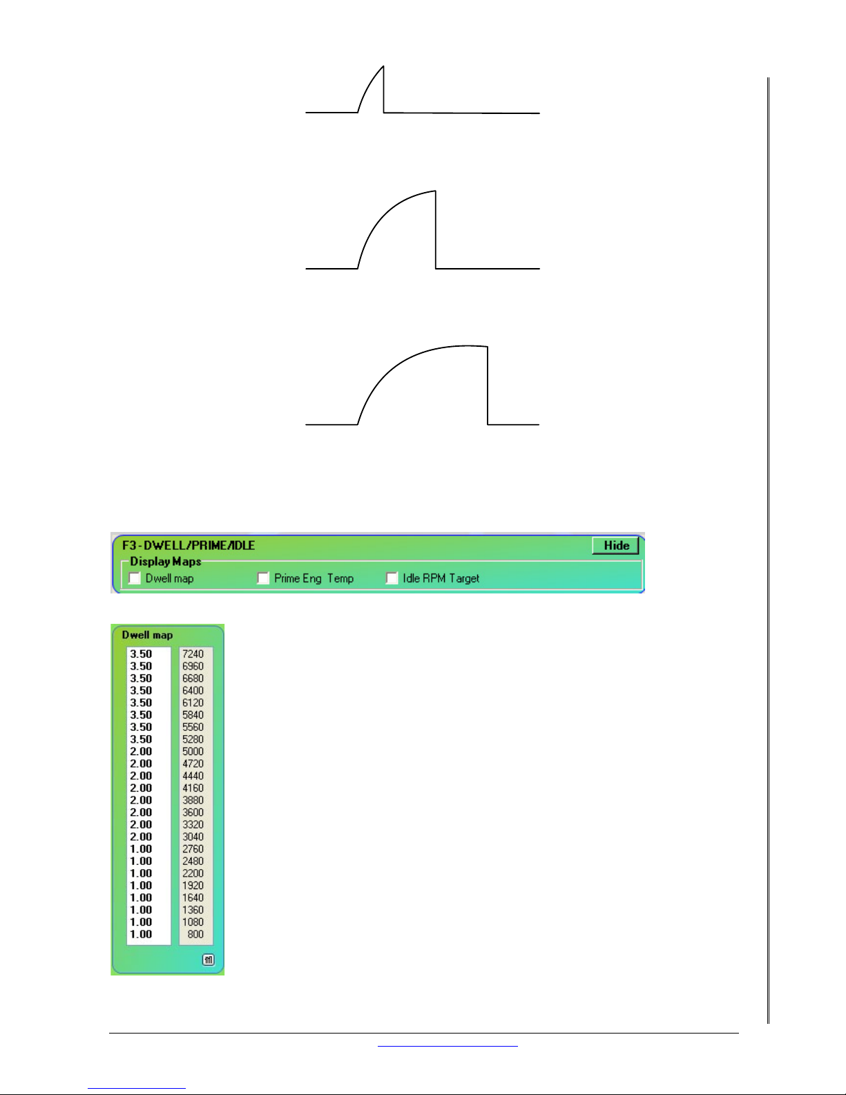
Yes. Setting the dwell time too long (20ms) will cause the coil to become saturated. A
saturated coil will overheat and will burn out over time. Setting th e dwell too short (1ms) will
not damage the coil. A very short dwell time will cause a weak spark and the engine may
misfire. To check if the coil has the right dwell time you will need an oscilloscope to measure
the current.
Page 35
LETRIPP II XMS4A DIY MANUAL V2.1 www.perfectpower.com 31
PERFECT POWER XMS4A – Engine Management System DIY MANUAL V2.1
Dwell too short
Dwell just right
Dwell too long
18.3 DWELL SETUP VIA SOFTWARE
Open the F3 Dwell + Prime + Idle map:
Enter a dwell curve:
Refer to LetRipp II Software User Guide for more details.
Page 36
LETRIPP II XMS4A DIY MANUAL V2.1 www.perfectpower.com 32
PERFECT POWER XMS4A – Engine Management System DIY MANUAL V2.1
19. SETTING UP PARAMETERS
The correct parameters need to be setup to get the XMS4A to function correctly on your
engine. Cylinders, ignition reference, Ignition advance/retard limits, Launch RPM limit, , Start
time, acceleration detection, min injection, LSU4 zero, boost gain will all be explained.
Your XMS4A unit may not have all the parameters but it will have the essential ones, so I will
cover them first.
Cylinders: Enter the number of cylinders your engine has.
Ignition reference: Enter the amount in degrees the pickup sensor is from the gap at TDC.
Ignition advance limit: Enter the amount of ignition advance in degrees that must not be
exceeded.
Ignition retard limit: Enter the amount of ignition retard in degrees that must not be
exceeded.
Start time: Enter the time in seconds that the fuel pump will run when the XMS4A is powered
up. The fuel pump will switch back on when the XMS4A sees RPM.
Acceleration detection: A small value of 10 is a fast detection and a high value 80 is slow
acceleration detection.
Launch RPM limit: Enter the RPM that the XMS4A must start the launch control.
Boost gain: Enter a low number, 1.00 for small gain and 10.00 for a large gain.
Minimum injection: Enter the time in milli seconds that the injectors must not open. A good
starting number is 1.2
Fuel Range: Enter a value from 0.1 to 10
Page 37

LETRIPP II XMS4A DIY MANUAL V2.1 www.perfectpower.com 33
PERFECT POWER XMS4A – Engine Management System DIY MANUAL V2.1
20. SYSTEM DEFINITION
Neg Crank Edge
Switches the trigger edge from positive to negative.
High CB1 Level
Switches the trigger level from low to high. Low level normally use with magnetic sensors.
Inverse TPS En
Switches the tps cursor from right to left or vice versa.
Fuel Extrap. En
Enables extrapolation between cells in the main fuel map.
Cam every 2 turn
Enables sequential operation provided that there is a cam signal..
Inj. Trim Enable
Enables the individual injector trim circuit.
Neg. CAM Edge
Switches the trigger edge from positive to negative
High CB2 Level
Switches the trigger level from low to high.
Launch Control
Enables the launch control circuit.
AMP Extrap. En
Enables extrapolation between cells in the AMP map.
SetP. Map Switch
Enables the XMS4 to switch between map A and map B electronically. If this has been enabled
then the earth switch for map change (pin 1 of 22) will be disabled.
Idle control en
Enables the idle control circuit.
Page 38
LETRIPP II XMS4A DIY MANUAL V2.1 www.perfectpower.com 34
PERFECT POWER XMS4A – Engine Management System DIY MANUAL V2.1
21. SET POINTS
All engines have devices that need to be activated at certain critical times, you will learn how
to activate these devices. They are activated via the XMS4A’s set points.
21.1 USES
• Fuel pump activation
• Cooling fan activation
• Shift lights
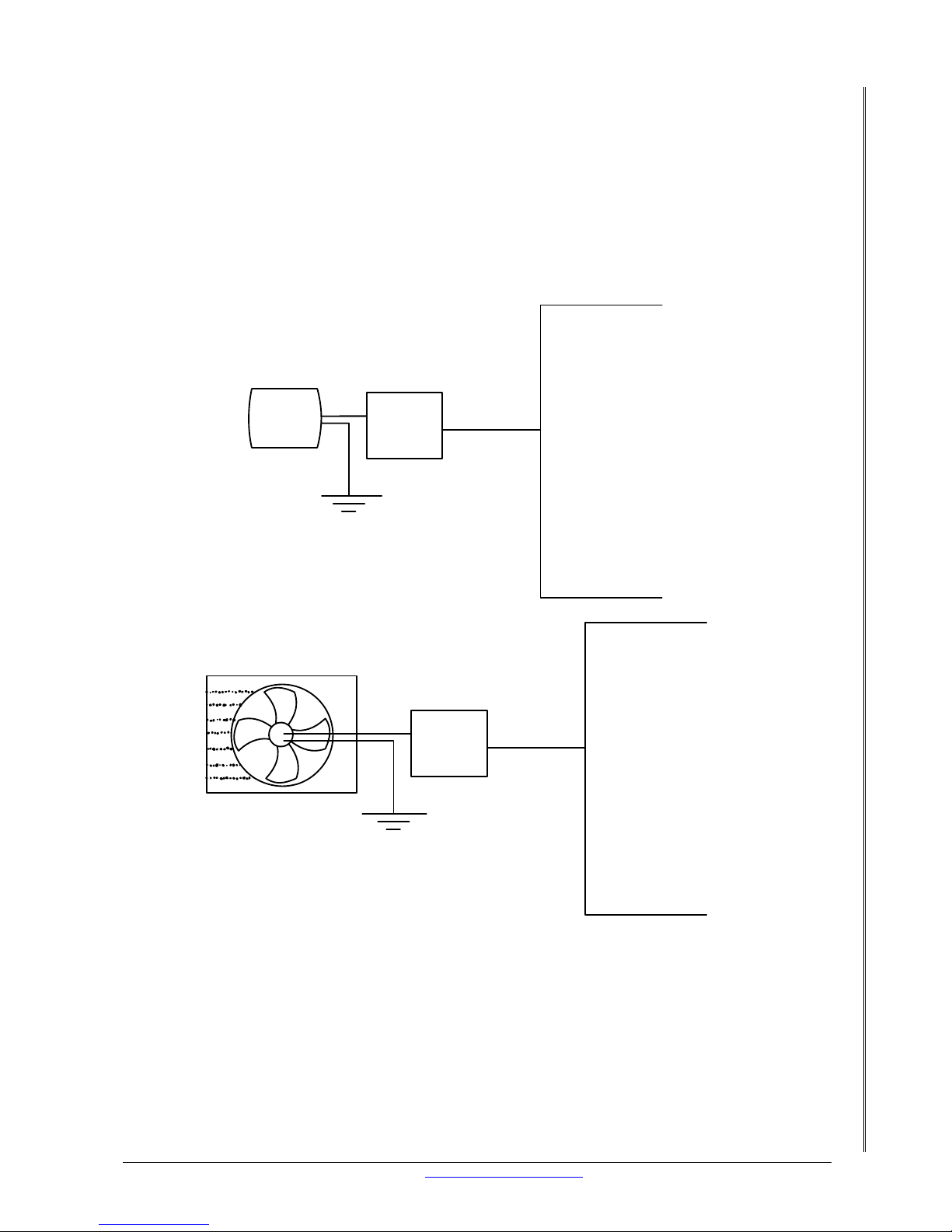
21.2 WIRING
XMS4
Auxillary
connector
Relay
Fuel
Pump
XMS4
Auxillary
connector
Relay
Radiator and Fan
Page 39
LETRIPP II XMS4A DIY MANUAL V2.1 www.perfectpower.com 35
PERFECT POWER XMS4A – Engine Management System DIY MANUAL V2.1
XMS4
Auxillary
connector
Relay
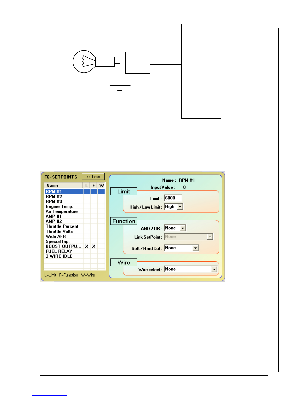
For details on how to wire a 4-pin relay see Section 16.2.
21.3 SETUP VIA SOFTWARE
Each auxiliary output can be set for a specific task. The Set point map (F6) is used for this
purpose.
22. CALIBRATION OF SENSORS
All sensors are not the same and each one needs to be setup so that the XMS4A displays the
correct values. We are going to take the different sensors air temp, engine temp, throttle
position and amp voltages and program the XMS4A to understand what voltage represents
what value.
Page 40
LETRIPP II XMS4A DIY MANUAL V2.1 www.perfectpower.com 36
PERFECT POWER XMS4A – Engine Management System DIY MANUAL V2.1
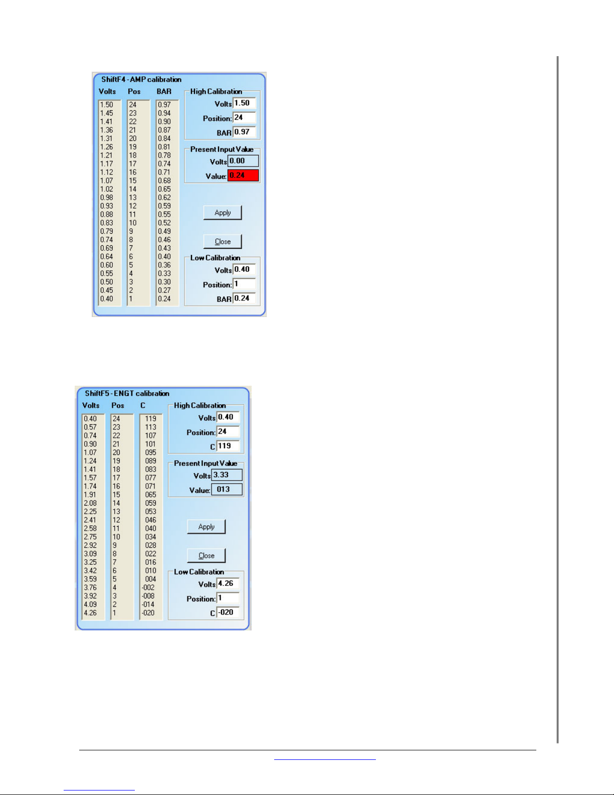
22.1 AMP
The AMP sensor is calibrated so the full range of the
sensor gets used. By that I mean a normally
aspirated engine will go to a maximum pressure of 1
bar. So your upper scale shouldn’t be more than 1
bar. With the amp connected and the ignition key on,
this sensor will generate a voltage, normally between
1 and 2 volts. This voltage represents the
atmospheric pressure. Now calibrate the lower and
upper scale so that the XMS4A shows the amp value
at 0.9 with just the ignition on. See the LetRipp
software guide for the actual steps on setting this up
in the software
22.2
ENGINE TEMP
This sensor must be calibrated so the XMS4A can
compensate for cold and hot conditions. You can place
the engine temp sensor in boiling water to get a hot
point reference. Put this voltage into the upper
calibration point. When the sensor cools down it will
have a lower voltage. You need to put in an educated
guess as to the lowest temperature the engine will
experience and what voltage this will be into the lower
calibration point.
Page 41
LETRIPP II XMS4A DIY MANUAL V2.1 www.perfectpower.com 37
PERFECT POWER XMS4A – Engine Management System DIY MANUAL V2.1
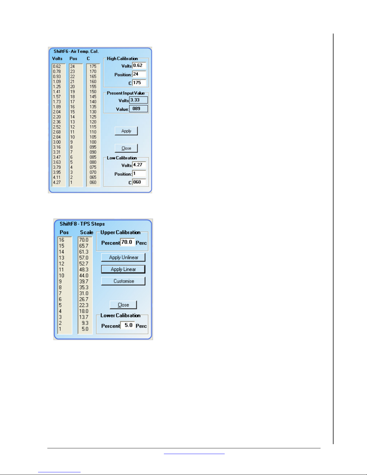
22.3 AIR TEMP
Air temperature is very important on boosted engines so
this sensor must be calibrated so the XMS4A can
compensate for cold and hot air conditions. You can
place the engine temp sensor in boiling water to get a
hot point reference. Put this voltage into the upper
calibration point. When the sensor cools down it will
have a lower voltage. You need to put in an educated
guess as to the lowest temperature the engine will
experience and what voltage this will be into the lower
calibration point.
22.4
THROTTLE POSITION
The throttle calibration is done so that the full 24
deflection sites are used. From no throttle to full throttle
is setup in the LetRipp software. See the LetRipp
software manual for throttle position calibration steps.
The throttle position sensor also generates a voltage for
no throttle and for full throttle. Take the voltage for no
throttle and add 5% to it. This will be the value for the
lower calibration point. Go to full throttle and minus 5%
from it. This will be the value for the upper calibration
point.
22.5
CONCLUSION
By using the LetRipp software guide and the LetRipp software your sensors are correctly
calibrated for the range they operate in.
Page 42
LETRIPP II XMS4A DIY MANUAL V2.1 www.perfectpower.com 38
PERFECT POWER XMS4A – Engine Management System DIY MANUAL V2.1
23. RPM
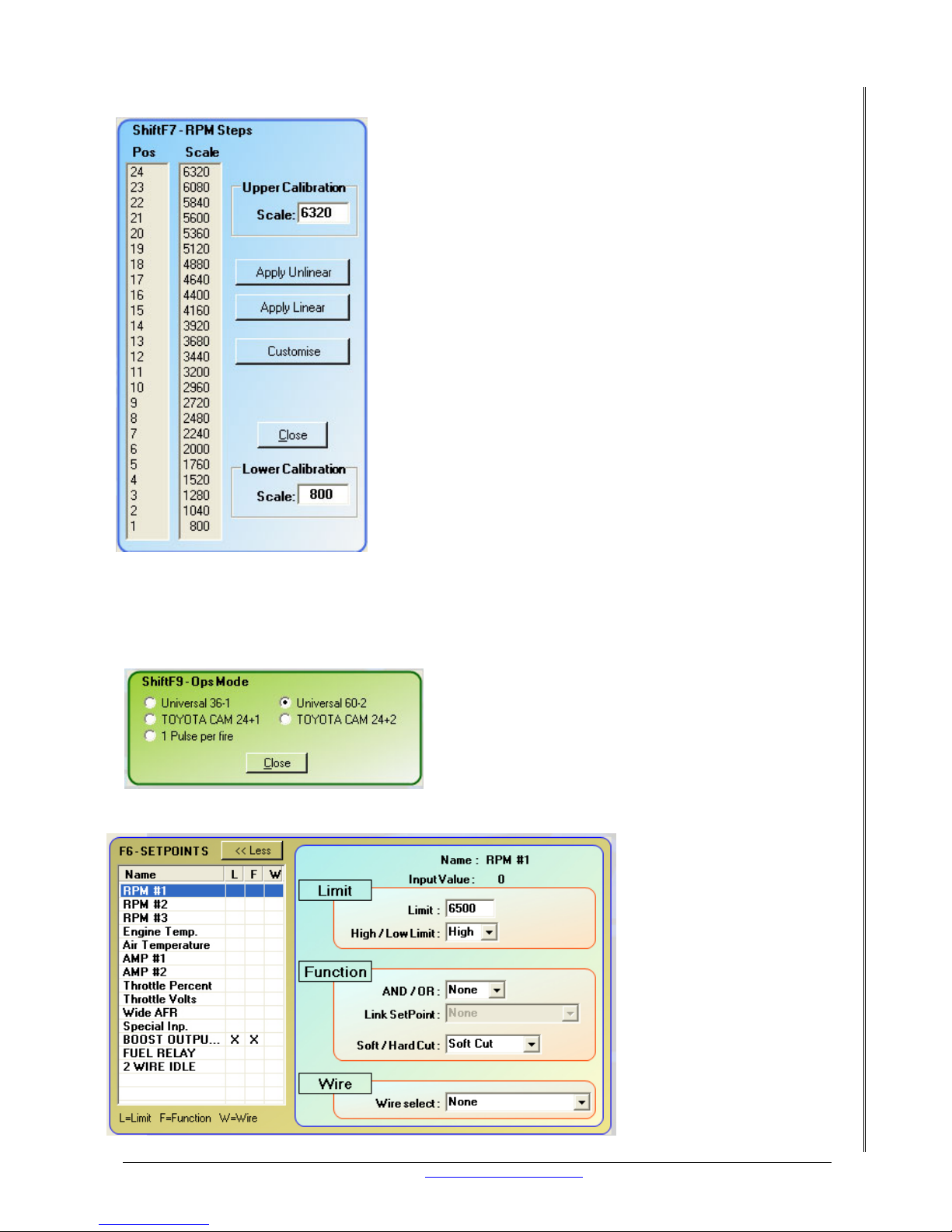
The RPM needs to be setup correctly so that the full range
of the engines rpm is utilized. RPM will be calibrated and the
operational mode will be set. Limits are going to be imposed
to protect the engine.
23.1
SETUP AND CALIBRATION VIA SOFTWARE
Open “config” then open “RPM calibration” The upper calibration scale would be the maximum
rpm that you would rev the engine to. The lower calibration scale is normally set at 600 rpm.
The “ops mode” must be the same as the trigger
wheel on the engine. If your trigger wheel is 60 – 2
then tick the radio button next to “universal 60 –2”
or select the trigger type you have. See section 12.1
for more details.
23.2 LIMIT
It is always a good idea to
have a rev limit. Why?
Well the rev limit will
prevent the engine from
exceeding its designed
capabilities. Bottom line
is, the limit is there to
protect the engine. You
can find out your engine’s
recommended RPM limit
from the manufacturer.
The rev limit is
programmed in the set
points and RPM #1, #2
and #3 can be used.
There are two types of
limits that can be set, soft
Page 43

LETRIPP II XMS4A DIY MANUAL V2.1 www.perfectpower.com 39
PERFECT POWER XMS4A – Engine Management System DIY MANUAL V2.1
cut and hard cut. The rpm limit in the screen shot below is set to 6500 and it is also a “soft
cut”.
The soft cut will randomly reduce the fuel by 33 40%. The fuel reduction is accomplished by “cutting”
“off” the fuel to different injectors. This reduces the
engine power and prevents the rpm from rising. See
the table below.
The hard cut setting will stop all injection if the rpm
limit is breached. Two rpm set points can be set for
the rev limit. The first limit can be set to be a soft cut and the second can be set to hard cut.
The hard cut is normally 200 rpm higher than the first limit.
23.3 CONCLUSION
The rpm has been calibrated to display the engine’s working rpm range. The ops mode
matches the trigger wheel.
24. WHAT TO DO BEFORE TRYING TO START THE ENGINE
This section will get you and the engine ready to be started. T iming will be checked and a fuel
map will be loaded. Some settings will be disabled to aid the starting process.
Load a map like the one included with your kit called “first start”. Check that the throttle is
only slightly open and not WOT. Disable the cold start by adding zero’ s to the entire “fuelling
temp” table. Check that the cooling fan works if the XMS4A is controlling a relay to turn the
cooling fan on at high temperatures. Change the high temperature to a temperature lower
than room temperature. Confirm that the fan comes on. Change the temperature setting back
to where it was and confirm that the fan switches off.
24.1 IGNITION SETUP WITH TIMING MARKS AND TIMING LIGHT
Now the ignition timing needs to be checked and adjusted to the right angle. If your engine is
using a distributor you can use any timing light. Wasted spark setups require a “dumb” or old
make of timing light. Using your timing light, clip it onto number 1 cylinder spark plug HT lead.
The timing light will blink a light every time the spark plug fires. Point the timing light at the
crank pulley where you made the timing marks in section 7. You can now see where the mark
on the crank pulley is in relation to the mark on th e engine block. Depending on which way
your motor turns you can see if the ignition is retarded or advanced. The two drawings below
show one engine at 10 degree advanced and –5 degree retard.
Crank pulley
Timing c over
TDC
0
Engine rotation
Crank pulley
Timing c over
TDC
0
Engine rotation
Cylinders Remaining Power
3 50%
4 40%
5 57%
6 40%
8 40%
Page 44

LETRIPP II XMS4A DIY MANUAL V2.1 www.perfectpower.com 40
PERFECT POWER XMS4A – Engine Management System DIY MANUAL V2.1
24.2 IGNITION ADJUSTMENT VIA SOFTWARE
You must set the ignition to be at 10 degrees at idle. So in the ignition map (F2) where the car
is idling set the tuning cells to 10. Check with the timing light what the ignition is on now. If
the ignition is at 10 degrees, well done, you can go to the next section. If it is not then you
need to adjust the ignition reference (ShiftF1). For adjusting retarded timing make the ignition
reference less. E.g.: go from 60 to a 55. For adjusting advanced timing make the ignition
reference higher. To get the correct ignition timing curve consult your engine manufacturer or
have a professional tuner set it up for you. Incorrect ignition timing can damage your
engine!
Note: The ignition reference must always be higher than the ignition point. The ignition
outputs are turned OFF if you have a reference of 30 and an ignition point of 31!
25. TIME TO START THE ENGINE
You are going to adjust timing, and fuel. You will load different maps into your XMS4A. If you
are unable to get the engine started go to section 28. Once the engine is running there are
some things that will need to be done, so let’s get to it! Having th e following items displayed
in the LetRipp software will help a lot.
• RPM
• AMP
• Injector m/s
25.1 FIRST THINGS TO DO WHEN CRANKING THE ENGINE
Under first time cranking you must check that you have rpm. Normally it is between 180 and
220 rpm. The amp reading should be between 0.85 and 1.0 bar with the ignition on. Under
cranking the amp reading should drop slightly and with the engine running it will drop down to
the lower multipliers. Check the injector m/s time under cranking to be between 5-6 m/s.
There are three ways the engine will startup.
Good/acceptable.
The engine idles between 800 – 1000 RPM and it sounds smooth.
Revs too high.
Adjust the throttle stop or set the ETC so the engine idles at an acceptable RPM.
It almost wants to start.
Increase the fuel range.
When the engine starts you will need to stabilize th e RPM if it is erratic. Adjust the throttle
stop (if it has one) to bring the rpm to 800. Get the fuel injection milli seconds (ms) between 2
to 3 m/s. Adjust the fuel range or the amp gradient to get the injector m/s right.
25.2
FIRST THINGS TO DISABLE WHEN THE MOTOR IS RUNNING
Disable the fuel engine temp and fuel air temp tables for now. We will use them later in the
manual. Disable the ignition map’s amp, engine and air tables. Disable the “AMP Extra. En” in
the system def.
Page 45
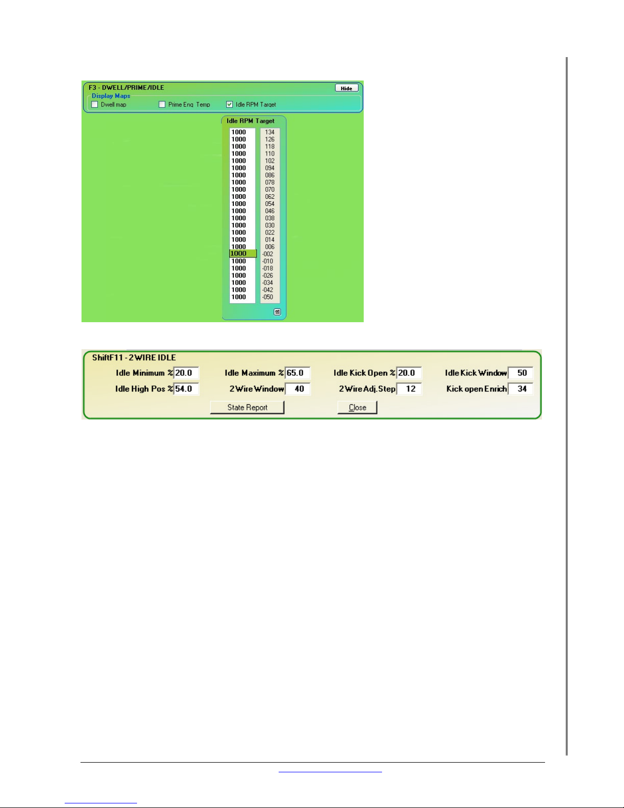
LETRIPP II XMS4A DIY MANUAL V2.1 www.perfectpower.com 41
PERFECT POWER XMS4A – Engine Management System DIY MANUAL V2.1
25.3 IDLE SETUP
The XMS4A can be programmed to
idle at different speeds as the
engine temperature changes. To
set the idle speed use the “F9”
map and the “Idle rpm target”
map.
25.4 FUEL SETUP WITH AMP
A good fuel map to start up on should have the same values in the main fuel map. The amp
multiplier should have the same values as the amp gradient . Now the only thing you may need
to setup is the fuel range. The “first start” map (which you have loaded already in the section
before this one) has a fuel range of 2.5 this number can be adjusted up or down depending
the amount of fuel needed. Only one number to tune makes for quick adjustment of the entire
fuel range.
Page 46
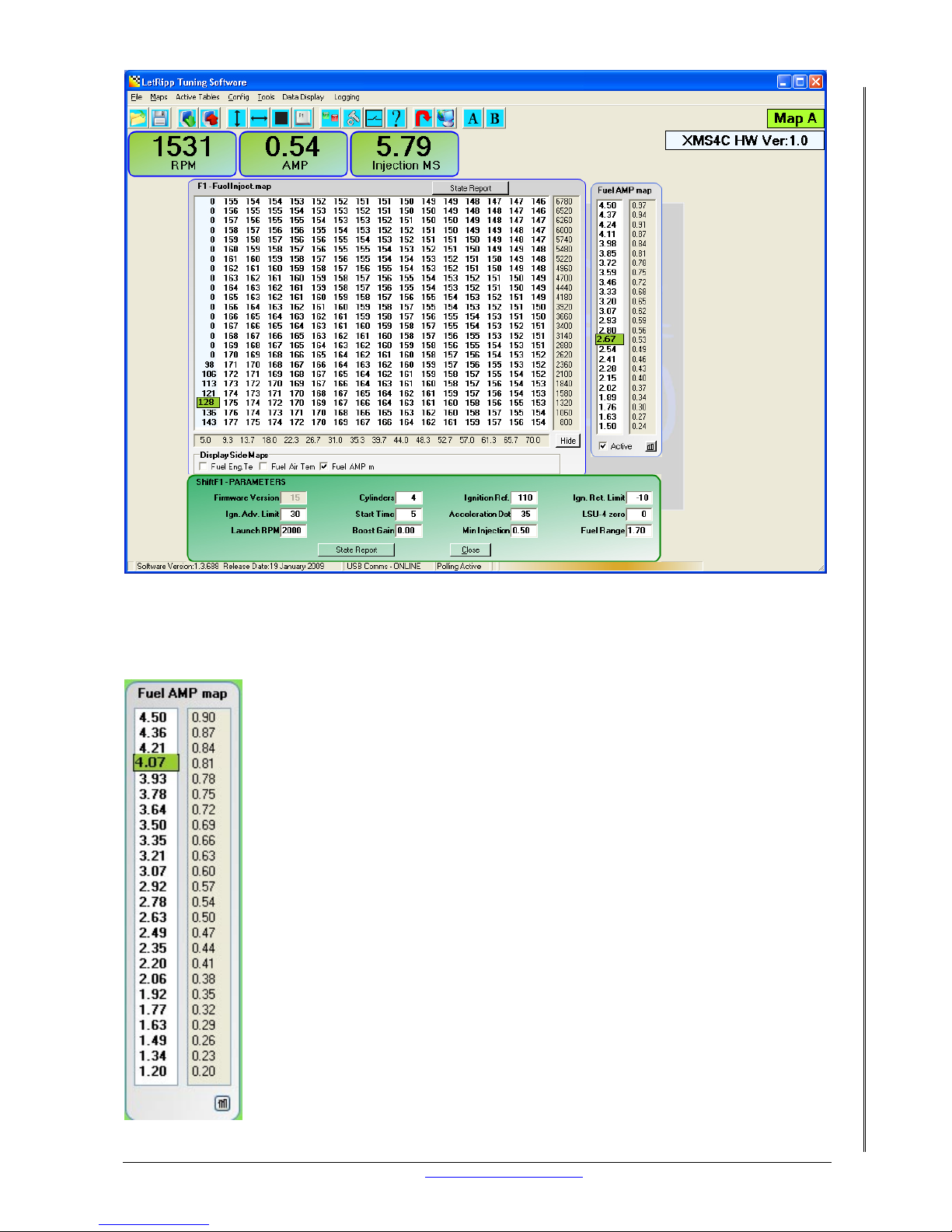
LETRIPP II XMS4A DIY MANUAL V2.1 www.perfectpower.com 42
PERFECT POWER XMS4A – Engine Management System DIY MANUAL V2.1
If the engine doesn’t rev up when the throttle is pushed you have two options:
Option 1:
The upper AMP multiplier must be increased. Then the AMP multipli er must be blended from
the upper multiplier to the idle multiplier. See the LetR ipp Soft ware guide for more details.
Page 47

LETRIPP II XMS4A DIY MANUAL V2.1 www.perfectpower.com 43
PERFECT POWER XMS4A – Engine Management System DIY MANUAL V2.1
Option 2:
Load the map called “AMP increased”.
Rule! If the manifold pressure increases by a factor of 3 then the fuel must increase
accordingly by a factor of 3, 5
25.5 CONCLUSION
Now the motor is idling between 800 – 1000 rpm. When the accelerator is pushed the motor
revs up smoothly. Your ignition in the LetRipp software matches the ignition on the motor.
26. LOOK HERE IF IT DOESN’T START
Your engine isn’t starting and you need some help? Read on. Your engine is running but you
want help in tuning go to section 29. There are many things that don’t work first time and I
will try to cover all of them.
26.1 POSSIBLE REASONS AND COMMON CHECKS
The obvious ones will be covered first.
Does the engine crank over?
If it doesn’t the starter motor may need replacement.
Make sure that you can turn the motor by hand.
Is there fuel in the tank?
I know but I have to ask, you never know.
Is the battery fully charged?
A weak battery will cause endless havoc, make sure your battery is 100%
Is there still fuel pressure at the injectors?
Check that the fuel pump is switching on
Is the XMS4A getting power?
Take the USB tuning cable off the XMS4A and see if the green LED comes on when the ignition
key is turned on.
Do you have spark?
Warning!!! Take extreme care whilst doing the following checks.
Single coil.
Take the ignition key and put it in your pocket. Take the coil lead off the distributor and place
it close to anything metal on the engine. The end of the lead must not touch the metal but it
must be quite close. Make sure that you can see the end of the lead when you turn the key.
Put the ignition key in and crank the engine. If you have spark you will see a blue light arching
between the end of the lead and the piece of metal.
Coil pack.
Unplug all the HT leads from the spark plugs. Get spark plugs that are new or are known to
work and insert them into the HT leads. Make sure that each spark plug is earthed onto the
engine and that you can see each spark plugs gap from the ignition. Insert the ignition key
and crank the engine.
Page 48

LETRIPP II XMS4A DIY MANUAL V2.1 www.perfectpower.com 44
PERFECT POWER XMS4A – Engine Management System DIY MANUAL V2.1
More in depth checks.
Are the injectors opening?
Unplug all the injector clips at the injectors not at the XMS4A. Now connect one injector pin to
battery ground. Take a 20 amp fused wire from the other injector pin and tap the positive
battery terminal. If the injector is work ing you should hear a clicking sound from th e injector
as you tap the positive battery. Test all the injectors to confirm status as working. Now plug
the injector clips back on.
Unplug the injector connector from the XMS4A. Now we are going to test the wiring from the
XMS4A to the injectors. Take a wire from a good ground point and tap each injector wire from
the inside of the connector.
Confirm that the injectors click as each injector pin is tapped.
Note the ignition must be on.
This isn’t law but most injector’s opening times are 1.4 ms some are faster and some are
slower. Idling below your injector’s opening time is not ideal. Another way to explain this
opening time would be this. An injector is a mechanical device like a door. When you open a
door it takes a while for you to get it fully open. An injector is the same, just much faster than
you opening a door. Now if the injector has not fully opened and you switch it off you don’t get
a proper spray pattern and it causes problems at idle. If you are having fuel prob lems at idle
consider this fact and increase the injector ms opening time.
27.
TUNING YOUR XMS4A FOR THE FIRST TIME
27.1 OPTIONS
Take your car to the local tuning expert and have them map the engine for you. You can map
the engine yourself if that is your plan.
27.2 TOOLS NEEDED
Lambda scanner, wideband is preferable. Laptop computer. Gas analyzer
27.3 FUEL TUNING
Lambda short term
Lambda long term
Air temp compensation
Engine temp compensation
CO MEASUREMENTS
Most garages and tune shops have a CO Analyzer. This is a very helpful tool and a good start
during the tuning process. It is very important that the CO Analyzer is well maintained and
calibrated.
You may ask “What am I looking for in a CO measurement?” This depends very much on what
you are looking for to get out of your engine! There are two extremes:
A) ECONOMY: You may run the engine at the most economical operating point
B) POWER: You may run the engine a little rich, but at the most powerful operating point.
A CO Analyzer has two advantages:
• Affordable price
• Most of the time it is a portable instrument, operating from 12 Volts.
You can use a portable CO Analyzer while you drive, but you may need to get used to the
delay in seeing the result of your actions.
Page 49

LETRIPP II XMS4A DIY MANUAL V2.1 www.perfectpower.com 45
PERFECT POWER XMS4A – Engine Management System DIY MANUAL V2.1
4 GAS ANALYSER
For real accurate tuning, and especially if you have modified the engine (any part which
influences the fuel burning process), you should check the validity of your modifications on the
Dyno with a 4 GAS ANALYSER.
The four gases are:
• HYDROCARBONS HC
• CARBON MONOXIDE CO
• OXYGEN O2
• CARBON DIOXIDE CO2
27.3.1.1 HYDROCARBONS (HC)
When analyzing the exhaust gas for HC, one actually measures the amount of un-burnt fuel in
parts per million (PPM) that have escaped the engine’s combustion process. Typical causes of
HC are:
• Inadequate spark duration,
• Ignition timing,
• Low compression,
• Air/Fuel mixture, and
• Other mechanical malfunctions.
27.3.1.2 CARBON MONOXIDE (CO)
CO is highly toxic, and measured as a percentage of the exhaust gas. It is formed when there
isn’t enough oxygen to convert carbon (C) in the fuel into carbon dioxide (CO2). CO only
forms when combustion has taken place. A typical cause for a high CO reading is too rich a
fuel mixture.
27.3.1.3 CARBON DIOXIDE (CO2)
CO2 is measured in percentage by volume of the exhaust gas. As a general rule, the engine is
operating at its best when CO2 is at its highest level of approx. 12-15%. The CO2
measurement will always peak at any value regardless of the cataly tic convert er. T his mak es it
a very good tuning indicator.
27.3.1.4 OXYGEN (O2)
O2 is a good indicator of a lean running engine. When an engine is running lean, oxygen will
increase proportionally as the air/fuel mixture becomes leaner. A normal engine at idle should
give an oxygen reading of 0.4 to 4%. Above 4%, the engine runs too lean, and below 0.5%
you are running too rich and wasting fuel.
27.3.1.5 MEASURING OXYGEN (LAMBDA)
Measuring oxygen or lambda is now the most used method in fuel tuning. In essence it
displays the air/fuel ratio (AFR) by means of measuring the REMAINING OXYGEN in the
exhaust. The relationship between CO Percentages and AFR
is indicated in a table below.
Page 50

LETRIPP II XMS4A DIY MANUAL V2.1 www.perfectpower.com 46
PERFECT POWER XMS4A – Engine Management System DIY MANUAL V2.1
POWER
RICH
LEAN
CO2
O2
CO
AIR / FUEL RATIO
0
2
4
6
8
10
12
14
16
89101112 13 141615
17 18
%
The above graph shows the general relationships. Some engines with extensive ignition
mapping can run on 0.5 CO, other (older) engines may need 3.5 CO to perform. The principle
remains the same: the most efficient engine is (nearly) the most powerful one.
Don’t underestimate the influence of the driver on the fuel consumption. The other factor is
the operating point. Unless you are racing, engines operate on the road at 30-50% of the
available power.
Page 51

LETRIPP II XMS4A DIY MANUAL V2.1 www.perfectpower.com 47
PERFECT POWER XMS4A – Engine Management System DIY MANUAL V2.1
27.3.1.5.1 RELATIONSHIP OF CO % TO AIR FUEL RATIO CONVERSIONS
CO% AFR CO% AFR CO% AFR
0.1
0.2
0.3
0.4
0.5
0.6
0.7
0.8
0.9
1.0
1.1
1.2
1.3
1.4
1.5
1.6
1.7
1.8
1.9
2.0
2.1
2.2
2.3
2.4
2.5
2.6
2.7
2.8
2.9
3.0
3.1
3.2
3.3
3.4
14.72
14.54
14.42
14.34
14.28
14.23
14.21
14.17
14.15
14.11
14.09
14.04
14.01
13.98
13.94
13.89
13.86
13.82
13.80
13.77
13.73
13.69
13.63
13.59
13.56
13.54
13.49
13.45
13.41
13.38
13.34
13.31
13.27
13.24
3.5
3.6
3.7
3.8
3.9
4.0
4.1
4.2
4.3
4.4
4.5
4.6
4.7
4.8
4.9
5.0
5.1
5.2
5.3
5.4
5.5
5.6
5.7
5.8
5.9
6.0
6.1
6.2
6.3
6.4
6.5
6.6
6.7
6.8
13.20
13.15
13.12
13.08
13.03
13.00
12.96
12.93
12.90
12.86
12.83
12.80
12.75
12.70
12.66
12.64
12.59
12.54
12.51
12.46
12.43
12.40
12.37
12.30
12.25
12.25
12.22
12.18
12.13
12.10
12.09
12.03
12.00
11.96
6.9
7.0
7.1
7.2
7.3
7.4
7.5
7.6
7.7
7.8
7.9
8.0
8.1
8.2
8.3
8.4
8.5
8.6
8.7
8.8
8.9
9.0
9.1
9.2
9.3
9.4
9.5
9.6
9.7
9.8
9.9
10.0
11.93
11.89
11.86
11.82
11.79
11.76
11.72
11.69
11.65
11.61
11.58
11.54
11.50
11.46
11.43
11.40
11.36
11.32
11.28
11.25
11.21
11.16
11.12
11.08
11.05
11.01
10.97
10.94
10.90
10.86
10.82
10.79
27.4 IGNITION TUNING
If you are going to tune the engine yourself then you must get the engines ignition curve from
the manufacturer. Trying to map the ignition on the road can lead to engine failure if the
wrong ignition is programmed. Ignition tuning on a dynamometer can be done with more
safety.
Page 52
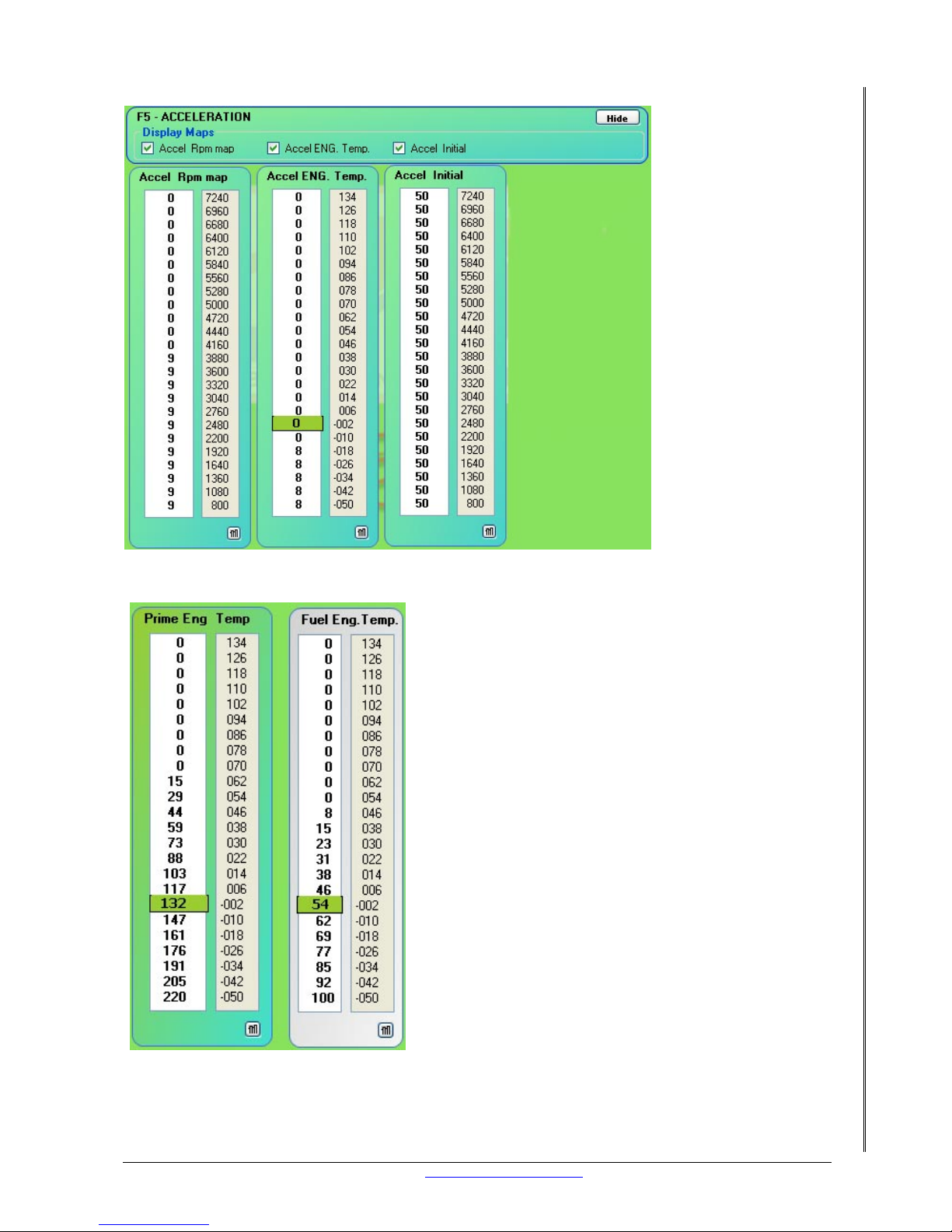
LETRIPP II XMS4A DIY MANUAL V2.1 www.perfectpower.com 48
PERFECT POWER XMS4A – Engine Management System DIY MANUAL V2.1
28. COLD START MAP
To get enough fuel
into the engine when
it is cold is important
to get it started. This
map is what makes it
possible in a few
steps. See the screen
shot below.
Should the engine still not start under cold conditions,
increase the amount of fuel at that temperature until it
starts. Increase the gradient of fuel for colder
temperatures and degrease the amount of prime for
warmer engine temperatures.
Page 53
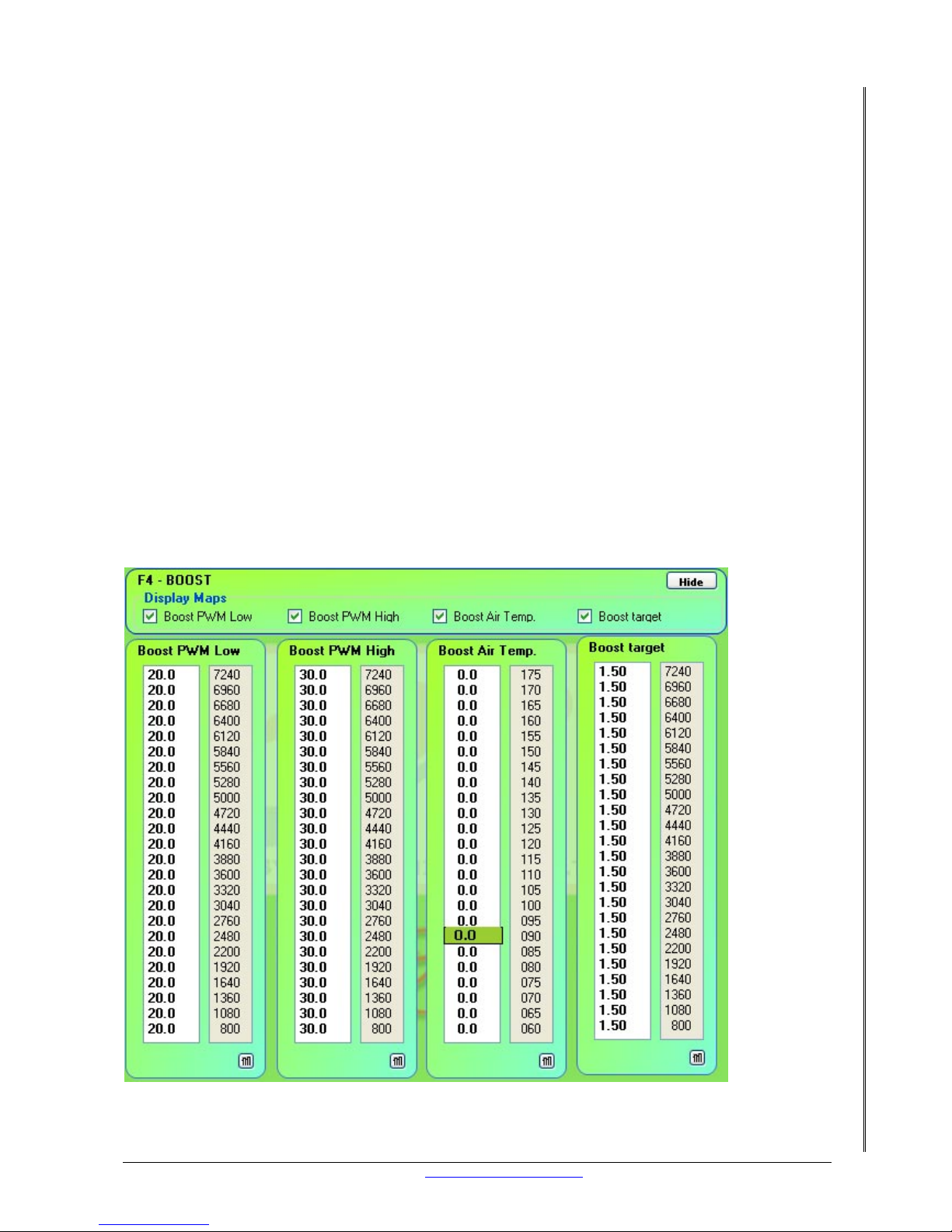
LETRIPP II XMS4A DIY MANUAL V2.1 www.perfectpower.com 49
PERFECT POWER XMS4A – Engine Management System DIY MANUAL V2.1
29. ACCELERATION ENRICHMENT
For smooth acceleration more fuel must be added, here is how to do it.
Once acceleration is detected the XMS4A can enrich the fuel mixture by Engine temp, RPM and
initial acceleration.
Start with zeros in all of these maps to see how the engine responds to acceleration. If it
responds poorly, add 20 to the “Accel Initial” map. Accelerate again, if the engine is more
responsive the increase the 20 to a 40. Note: All three of these maps influence acceleration so
you will need to adjust each map until the engine responds the way you want it to.
30. SETTING THE BOOST CONTROL UP
This section explains how to setup your XMS4A for open or closed loop boost control. This
section only applies to “turbo” charged engines.
30.1 CLOSED LOOP
This implies that the XMS4A will regulate the boost to a set pressure by modifying the PWM
output. What is needed for any type of boost control is the following:
• An available auxiliary output.
• A turbo canister, normally with a low pressure rating of 0.2 bar.
• A bleed solenoid, normally with two or three air pipes.
• An AMP sensor that will cover the desired pressure range.
Page 54
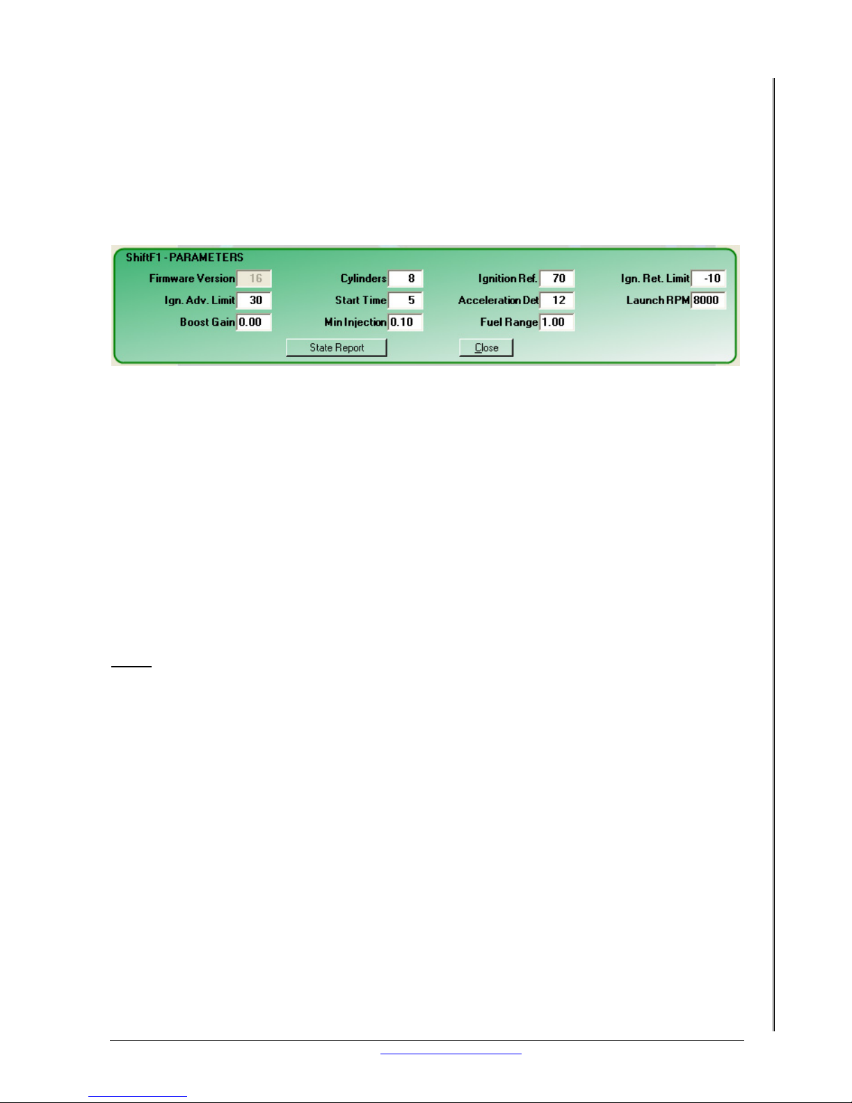
LETRIPP II XMS4A DIY MANUAL V2.1 www.perfectpower.com 50
PERFECT POWER XMS4A – Engine Management System DIY MANUAL V2.1
The way the closed loop works is as follows:
A) Run the engine under boost (full throttle) and adjust the PWM High table entry so that it
yields an acceptable boost HIGHER than your canister pressure. Precise boost pressure is
not required, but you must confirm that you have control.
B) Start off with a safe pressure amount, LESS than the final target pressure you would like
to achieve.
C) Throttle back, and repeat the setting of the PWM Low table. The numbers should be a little
lower, indicating LESS bleed for lower exhaust gas flow.
D) The engine should be drivable at this time.
E) Enter real targets in the target map.
F) Enter a small number in th e “Boost Gain” (CONFIG: PARAMETER) entry field.
G) At this point you will see that you have CLOSED T HE CONTROL LOOP, and that the Target
pressure is controlled
H) If the loop control is insufficient: increase the gain. If the loop becomes unstable decrease
the gain. If the gain is too critical, then you may have to put a ‘restrictor’ in the boost pipe.
NOTE: The XMS4A can increase the pressure above the canister’s rating but cannot
decrease it.
30.2 VIA PWM
The boost pressure is mapped via two throttle positions, 1 – 8 and 9 – 16 (low, high).
A) Assign a wire in the SETPOINT screen to the BOOST CONTROL function
B) Choose some settings in the PWM Low table in PERCENTAGE. “99” means 100% bleeding!
Do the same with the PWM High table.
C) Adjust the map so that the boost is what you want it for each rpm site
Note:
During operation, the BLEEDING (PWM) is controlled by the two columns of throttle
position: 1-8 and 8-16 and is modified by the deviation from the target time to the gain. With
the gain setting of ZERO, the deviation is eliminated and thus no adjustment is made to
achieve the target.
31. LAUNCH CONTROL
This feature is ideal for turbo charged engines to eliminate turbo lag.
31.1 USES
It eliminates turbo lag and allows the turbo to “spool up” on the starting line. To get this
working you will need to fit a switch onto the clutch. The switch must be closed (connected to
ground) when the clutch pedal is pressed and be open when the clutch pedal is released. The
switch input is on pin 20 of the 22 pin XMS4A connector.
For the technically minded this is how the launch control works. Once the SW2 input is closed,
the XMS4A waits for the RPM to exceed the pre-set limit. If the RPM limit is reached, the
XMS4A will retard the ignition to hold the RPM close to the limit. The XMS4A will also reduce
the fuel by 50% by using the launch fuel cut limit to help keep the rpm from creeping. You can
now open the throttle more, but the engine RPM will increase by a small amount only. At this
Page 55

LETRIPP II XMS4A DIY MANUAL V2.1 www.perfectpower.com 51
PERFECT POWER XMS4A – Engine Management System DIY MANUAL V2.1
time “flames” will come out of the exhaust and the turbo will glo w red-hot very quickly. As
soon as you release the clutch, the switch will open and the ignition and fuel return to normal.
XMS4
Pin 20
Launch Switch
31.2 SETUP VIA SOFTWARE
In the parameters map, set the launch RPM to the target you want to launch at. The ignition
retard limit must be set to a point that prevents the engine from going higher than the launch
target. The launch fuel cut must also be set 200 RPM higher than the launch target RPM.
Select Launch control in system def map to enable the SW2 for launch control.
WARNING: The above process can put a lot of strain on your gearbox, clutch and
other drive train, and may cause severe damage to drive train.
31.3 CONCLUSION
With the clutch switch installed and all the paramet ers enabled the engine has launch control
and that means no turbo lag.
32. TROUBLESHOOTING
Here we will go through every possible reason that we can think of as to why the engine is not
running and we will offer solutions.
32.1 FUEL
Fueling problems are the biggest cause for the engines failure to perform or even start.
32.2 PRESSURE
Normal fuel pressure under cranking must be between 2 and 3 bar. Confirm with a fuel
pressure gauge that the pressure stays at 2 – 3 bars at all times. Should the pressure drop to
1 bar or less under cranking then you will need to replace the following it ems:
• Fuel filter
• Fuel pump
• Fuel pressure regulator
Should this not solve the pressure problem see section 10 on how the fuel system should be
installed.
The fuel map could be too lean. Increase the fuel range. Make the fuel amp multiplier steeper.
Load the “richer amp” map.
32.3 IGNITION
Incorrect ignition timing can cause poor performance or not allow the engine to start.
Page 56
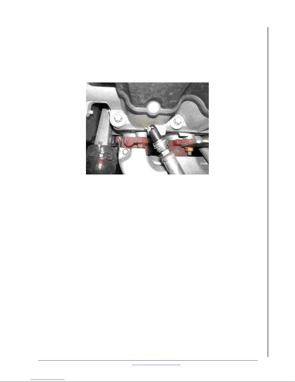
LETRIPP II XMS4A DIY MANUAL V2.1 www.perfectpower.com 52
PERFECT POWER XMS4A – Engine Management System DIY MANUAL V2.1
32.4 SPARK PLUGS
Take one spark plug lead and a working spare spark plug to check that you have spark under
cranking. The spark plug must be earthed when you do this test. If you can see the plug spark
then repeat the test on all the other leads. Now you have confirmed that you have spark on a
known working spark plug using all of your ignition leads. Take the all the sparkplugs out and
run the same test on each of them. If any fail to spark then replace all the sparkplugs with
new ones.
32.5 COIL
Coils can get damaged and sometimes you can see cracks or bloated areas on a coil that
clearly shows that the coil is now useless. If you can see obvious damage to the coil then
replace it straight away. If no visible damage to the coil can be seen you will n eed to test the
coil in the following ways:
32.6 TWO WIRE COIL
One wire is +12 volts and the other wire goes to the ignition amplifier. Take the wire off the
ignition amplifier and lengthen it so it can reach the negative terminal on the battery, I will
refer to this wire as the trigger wire. Don’t secure it to the battery. Take the coil lead off the
distributor and place the end close to a piece of metal on the engine. There must be an air gap
between the lead and the metal. Take the trigger wire and tap it onto the negative battery
terminal. If you see a spark from the end of the coil lead to the metal on the engine as you
tap the wire on the battery then the coil is good. If you still do not have any spark then the
coil must be replaced.
Note: DO NOT leave the trigger wire connected to the negative battery terminal. Th is will
cause damage to the coil.
32.7 THREE WIRE COIL
This type of coil has +12 volts and two signal inputs from the ignition amplifier. This coil is
referred to as a wasted spark coil pack. Take both wires off the ignition amplifier and leng then
them so they can reach the negative terminal on t he battery, I will ref er to these wires as the
trigger wire 1 and 2. Don’t secure them to the battery. Take the coil leads off of the spark plug
and place the ends close to a piece of metal on the engine. There must be an air gap between
the lead and the metal. Take the trigger wire 1 and tap it onto the negative battery terminal.
Page 57

LETRIPP II XMS4A DIY MANUAL V2.1 www.perfectpower.com 53
PERFECT POWER XMS4A – Engine Management System DIY MANUAL V2.1
If you see a spark from the end of two coil leads to the metal on the engine as you tap the
trigger 1 wire on the battery then that channel of the coil is good. Repeat the test with the
trigger 2 wire. If you still do not have any spark then the coil must be replaced.
Note: DO NOT leave the trigger wire connected to the negative battery terminal. Th is will
damage the coil.
32.8 FOUR WIRE COIL:
This type of coil has +12 volts and two signal inputs from the ignition amplifier and a ground
connection. Some of these coils have built in amplifiers; consult the manufacturer of the coil
pack for wiring details. This coil is referred to as a wasted spark coil pack. Take both wires off
the ignition amplifier and lengthen them so they can reach the negative terminal on the
battery, I will refer to these wires as the trigger wire 1 and 2. Don’t secure them to the
battery!!!!! Take the coil leads off of the spark plug and place the ends close to a piece of
metal on the engine. There must be an air gap between the lead and the metal. Take the
trigger wire 1 and tap it onto the negative battery terminal. If you see a spark from the end of
two coil leads to the metal on the engine as you tap the trigger 1 wire on the battery then that
channel of the coil is good. Repeat the test with the trigger 2 wire. If your coil pack has built in
amplifiers then you must tap the trigger wires onto t he posit ive batt er y termin al. If you still d o
not have any spark then the coil must be replaced.
NOTE: DO NOT leave the trigger wire connected to the negative battery terminal.
This will cause damage to the coil.
NOTE: Coils that have built in amplifiers must get wired directly to your XMS4A
ignition outputs and not through an ignition amplifier. If your coil has built in
amplifiers but requires a negative signal to trigger, a Perfect Power Auto Inverter
will be needed.
There are many other coils on the market and I can’t list all of them. If I have not mentioned
your particular type of coil you must consult the manufacturer for the wiring details and run
the above tests on your coil to determine its state of wellness.
32.9
TRIGGER WHEEL
Should the XMS4A and LetRipp software not display any RPM under cranking you could have
two problem areas, the trigger wheel and the trigger pickup sensor. First the trigger wheel,
the XMS can work with certain types of trigger wheels only. See section 12.1 for more details.
If you are using a magnetic sensor you must use a ferrous metal as the trigger wheel.
32.10 TRIGGER SENSOR
The trigger sensor could be too far from the trigger and therefore not generate a signal. If the
air gap between the sensor and the toothed wheel is larger than 0.8mm this can cause
problems with the XMS4A’s RPM reading which will cause many oth er problems. Bottom line;
make the gap between the sensor and the toothed wheel 0.8mm no more no less. The
magnetic pickup sensors are quite durable but they can also get damaged. Check the area of
the sensor where the magnet is for signs of impact. Another way to test a magnetic sensor is
to see if it can hold its own weight. If it cannot stick upside down to a piece of mild steel then
is must be replaced. Don’t use this test on a hall or optical sensor.
You can also use a multimeter to see if a magnetic sensor is generating a signal under
cranking. When the voltage across the two wires is measured with a multi-meter on DC, you
will get no? If you measure with a multi-meter on AC, you will get a reading. This will at lea st
tell you if your sensor is trying to work.
If you are using a hall or optical pickup sensor it must be correctly wired to work. Consult the
manufacturer for wiring information.
Page 58

LETRIPP II XMS4A DIY MANUAL V2.1 www.perfectpower.com 54
PERFECT POWER XMS4A – Engine Management System DIY MANUAL V2.1
32.11 ENGINE FAILURE, NO COMPRESSION
The engine itself has to be mechanically sound if it is to run. Most common things wh ich cause
the engine to not start are as follows:
• Broken cam belt or cam chain. The easiest way to see if the belt or chain is broken is to
watch the cam pulley under cranking. If the cam pu lley doesn’t turn then the belt or
chain is broken. If you are unable to see the cam pulley, take the oil filler cap off and
you should be able to see the camshaft.
• No Compression. The best way of checking this is with a compression tester. It is a
relatively inexpensive tool that comes with inst ructions on how to use it.
Page 59
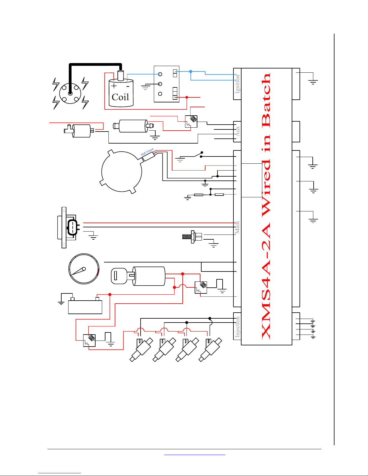
LETRIPP II XMS4A DIY MANUAL V2.1 www.perfectpower.com 55
PERFECT POWER XMS4A – Engine Management System DIY MANUAL V2.1
33. BASIC XMS4A-2A WIRING DIAGRAM
This is a basic diagram for wiring the unit in batch and serves as a guide only.
Pin 1 of 6
Pin 2 of 6
Pin 4 of 6
Blue Fire
Ign #1
Ign #2
Pin 1 of 4
Pin 2 of 4
Pin 3 of 4
Pin 4 of 4
Switched+12volts
Pin 1 of 22
Pin 9 of 22
Map A/B
Pin 7 of 22
Pin18 of 22
Pin 5 of 22
Pin 10 of 22
Pin 22 of 22
Fuel Pump
1
2
3
4
5
6
7
8
0
+
-
Pin 3 of 22
Pin 11 of 22
Pin 14 of 22
Switched+12volts
Ignition
Key
Battery
RPM
TPS
IAC valve
1234
Engine Temp
Battery +12volts
Pin 2 of 8
Pin 6 of 8
Pin 5 of 12
Pin 12 of 12
Pin 6 of 12
Pin 11of 12
Switched+12volts
Switched+12volts
Pin 9 of 22
Pin 13 of 22
Pin 3 of 22
Pin 9 of 22
Pin 2 of 22
2k2 2k2
CB1-
CB1+
Pin 10 of 22
1 Pulse
Per
Fire
Page 60
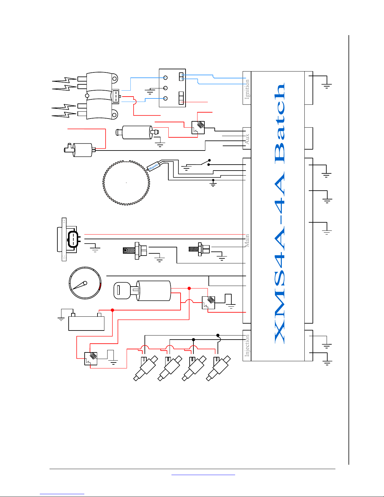
LETRIPP II XMS4A DIY MANUAL V2.1 www.perfectpower.com
34. BASIC XMS4A-4A WIRING DIAGRAM
This is a basic diagram for wiring in batch and serves as a guide only.
Pin 1 of 6
Pin2 of 6
Pin 4 of 6
Blue Fire
Coil for 1 & 4
Coil for 2 & 3
1
2
3
Ign #1
Pin 1 of 4
Pin 2 of 4
Pin 3 of 4
Pin 4 of 4
Switched+12volts
Pin 1 of 22
Pin 2 of 22
Pin 13 of 22
Pin 9 of 22
Pin 7 of 22
Pin18 of 22
Pin 17 of 22
Pin 5 of 22
Pin 2 of 8
Pin 10 of 22
Pin 22 of 22
Fuel Pump
56
PERFECT POWER XMS4A – Engine Management System DIY MANUAL V2.1
1
2
3
4
5
6
7
8
0
+
-
Pin 3 of 22
Pin 11 of 22
Pin 14 of 22
Pin 6 of 8
Pin 4 of 8
Pin 8 of 8
Switched+12volts
Switched+12volts
Switched+12volts
Ignition
Key
Battery
RPM
TPS
60-2
Crank
IAC valve
1234
Air Temp
Engine Temp
Battery +12volts
Pin 3 of 22
Map Switch
Ign #2
Switched+12volts
 Loading...