

Page 1
®
Fastener Removal System
User Guide
SYSTEM PART NUMBERS
CP1-SY-111
CP1-SY-141
CP1-SY-160
CP1-SY-121
CP1-SY-150
CP1-SY-170
CP1-SY-131
CP1-SY-151
TM
Page 2
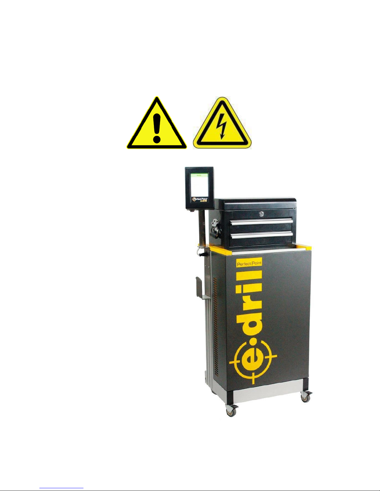
WARNINGS:
This fastener removal system should
only be operated by factory trained
authorized operators.
The E-Drill system is designed, built and
calibrated to work with factory genuine
parts and accessories, the use of nonauthorized components, electrodes, or
accessories can result in airframe
damage, tool damage, personal injury, or
death. Lethal high voltages are present
throughout the Power Supply Cabinet.
Follow all Warning and Caution
statements outlined in this User Guide
and all equipment Warning placards. Do
not proceed with any periodic
maintenance until factory trained and
authorized, and this document has been
thoroughly reviewed and understood.
Only trained, authorized technicians
should attempt tool use, tool selection,
adjustments, dielectric system
replenishment, and periodic
maintenance. This unit is not field
repairable; if any malfunctions are
encountered please contact Perfect
PointTM EDM Corporation immediately for
service.
Product specifications are subject to
change, and photographs in this
document may not match the current EDrill product combinations exactly.
Page 3

15192 Triton Lane
Huntington Beach, CA 92649
Office Tel: 714-892-3400
Hotline Tel: 714-891-6533
www.ppedm.com
User Guide
Document No.
61-101
Revision:
107
Date:
10/18/2018
This document is the property of PPedm Corp. and contains proprietary and/or patented information and may not be reproduced in
part or in whole without the express written permission of the company. Perfect Point logo, Perfect Point
TM
and E-Drill
®
are
trademarks of PPedm, Corp. US and worldwide patents pending.
Page 3 of 76
Limited Warranty Statement
Perfect Point EDM Corp. warrants to the end user that its products will be free from defects in material and
workmanship for a period of twelve (12) months from the date of delivery, but not more than eighteen (18) months
after date of shipment, and the successful completion of operator equipment use and maintenance training. This
warranty extends only to the original purchaser, is expressly in lieu of all other warranties, expressed or implied,
and is further in lieu of all other liabilities or obligations for any consequential damages or losses incurred by the
buyer in connection with the purchase or use of the product.
This warranty applies to systems subjected to normal operating conditions established by PPedm and explicitly
excludes equipment subjected to:
• User alteration.
• Accident or damage caused by the end-user.
• Improper handling, installation, maintenance, application, or contamination as established by PPedm
equipment operating instructions and preventative maintenance.
• Use with improper voltage.
• Use contrary to the operation instructions, and failure to properly service and maintain per PPedm
instructions.
• The use of non-authorized components, electrodes, or accessories.
Use of counterfeit electrodes will result in eccentric cuts (which will cause airframe damage)
incorrect cut depths, cutting times and electrode life. Use of counterfeit electrodes will also
invalidate the warranty. PPEDM will not repair systems or components damaged by the use of
counterfeit electrodes.
• Unauthorized disassembly, repair, or alteration by anyone other than PPedm Corp. No allowances will
be made for repairs or alterations effected without specific written authorization from PPedm.
This warranty does not cover:
• Normal wear and tear of soft goods (seals, hoses, cables etc.), E-Drill Adapters, Guides, Locators, Punch
Pins or Punch Guides and other fixtures or tools.
Credit will NOT be allowed nor shipment accepted on any machine or component thereof without Perfect Point’s
prior written consent and issuance of a PPedm Return Material Authorization (RMA).
PPedm will at its option, repair or replace any defective machine or component thereof for the specified warranty
period. PPedm reserves the right to substitute new equipment and/or improve the part(s) on any machine or part
thereof judged defective without further liability. Machines or components thereof will be repaired and the warranty
time continued.
All machines or components thereof returned for warranty consideration MUST NOT HAVE BEEN TAMPERED
WITH and all anti-tamper seals and/or striping must be intact. Removed or destroyed anti-tamper seals and/or
striping will be cause to VOID these warranty terms and conditions.
Liability Limitations: Under no circumstances shall PPedm have any liability for liquidated damages or collateral,
consequential, or special damages loss of production or progress of production, whether resulting from delays in
delivery or performance, breach of warranty, negligent manufacture or otherwise. Purchaser agrees to indemnify
and hold harmless PPedm from all claims by third parties in excess of these limitations.
THIS WARRANTY IS THE SOLE WARRANTY OF PPedm AND ANY OTHER WARRANTIES EXPRESSED OR
IMPLIED IN FACT, INCLUDING ANY WARRANTIES OF MERCHANTABILITY AND FITNESS FOR USE, ARE
HEREBY SPECIFICALLY EXCLUDED.
Page 4

15192 Triton Lane
Huntington Beach, CA 92649
Office Tel: 714-892-3400
Hotline Tel: 714-891-6533
www.ppedm.com
User Guide
Document No.
61-101
Revision:
107
Date:
10/18/2018
This document is the property of PPedm Corp. and contains proprietary and/or patented information and may not be reproduced in
part or in whole without the express written permission of the company. Perfect Point logo, Perfect Point
TM
and E-Drill
®
are
trademarks of PPedm, Corp. US and worldwide patents pending.
Page 4 of 76
WARNING WARNING WARNING
The USE of Counterfeit Electrodes Can Cause Damage to the
E-Drill, Aircraft, Aircraft Components, and Aircraft Structures.
THIS IS A SERIOUS SAFETY ISSUE!
Perfect Point electrodes are manufactured to exacting
standards and are certified for use with E-Drill systems.
Performance and control are matched to specific alloys.
Concentricity, Depth Control, Cut Diameter and Electrode Life
will not be maintained outside of these specifications.
The USE of Counterfeit Electrodes Will Violate the E-Drill
System warranty and Perfect Point WILL NOT Service E-Drill
Systems that USE Counterfeit Electrodes
For the Protection of Your E-Drill System and the safety of the
Application for Which You Are Using the E-Drill
DO NOT USE COUNTERFEIT ELECTRODES!
Only genuine electrodes supplied in original Perfect Point
packaging should be used in your system! If you suspect you
have received COUNTERFEIT ELECTRODES, please contact
the Perfect Point Support Hotline to Report.
1-714-891-6533
WARNING WARNING WARNING
Page 5

15192 Triton Lane
Huntington Beach, CA 92649
Office Tel: 714-892-3400
Hotline Tel: 714-891-6533
www.ppedm.com
User Guide
Document No.
61-101
Revision:
107
Date:
10/18/2018
This document is the property of PPedm Corp. and contains proprietary and/or patented information and may not be reproduced in
part or in whole without the express written permission of the company. Perfect Point logo, Perfect Point
TM
and E-Drill
®
are
trademarks of PPedm, Corp. US and worldwide patents pending.
Page 5 of 76
Perfect Point EDM Software End-User License Agreement (EULA)
IMPORTANT- READ CAREFULLY: This End-User License Agreement (“EULA”) is a legal agreement between
the user (either an individual or a single entity) and Perfect Point EDM Corp. (“PERFECT POINT”), the
manufacturer of the E-DRILL you have acquired, that includes certain Perfect Point software product(s) installed
on the E-DRILL system and equipment (“PPEDM SOFTWARE”). The PPEDM SOFTWARE includes computer
software, the associated media, any printed materials, any “on-line” or electronic documentation, upgrades and
recovery media. By using the PPEDM SOFTWARE, you agree to be bound by the terms of this EULA. If you do
not agree to the terms of this EULA, Perfect Point declines to license the PPEDM SOFTWARE to you. In such
event, you may not use the PPEDM SOFTWARE, and you should promptly contact PERFECT POINT for
instructions on return of the entire product.
PERFECT POINT SOFTWARE LICENSE
The PPEDM SOFTWARE is protected by copyright laws and international copyright treaties, as well as other
intellectual property laws and treaties. The PPEDM SOFTWARE is licensed, not sold.
1.
GRANT OF LICENSE. This EULA grants you the following rights:
• Software. You may use the PPEDM SOFTWARE as installed on the E-DRILL.
2.
OTHER RIGHTS AND LIMITATIONS.
• Limitations on reverse engineering, Decompilation and Disassembly. You may not reverse
engineer, decompile, or disassemble the PPEDM SOFTWARE.
• Single E-DRILL. The PPEDM SOFTWARE is licensed with the E-DRILL as a single integrated
product. The PPEDM SOFTWARE may only be used with the E-DRILL.
• Rental. You may not rent or lease the PPEDM SOFTWARE without prior written approval from
PERFECT POINT.
• Software transfer. You may permanently transfer all your rights under the EULA only as part of a sale
or transfer of the E-DRILL, provided you retain no copies, b) transfer all of the PPEDM SOFTWARE
(including all component parts, the media, any upgrades, and this EULA, c) you notify PERFECT
POINT of the new user, and d) the recipient agrees to the terms of this EULA.
• Termination. Without prejudice to any other rights, PERFECT POINT may terminate the EULA if you
fail to comply with its terms and conditions. In such event, you must return the entire product to
PERFECT POINT, and all its component parts.
3.
COPYRIGHT. All title and copyrights in and to the PPEDM SOFTWARE (including but not limited to any
images, photographs, animations, video, audio, music, text and “applets,” incorporated into the PPEDM
SOFTWARE), and the accompanying printed material, are owned by PERFECT POINT. You may not copy
the printed materials accompanying the PPEDM SOFTWARE, without prior written approval from
PERFECT POINT. All rights not specifically granted under this EULA are reserved by PERFECT POINT.
This Software Agreement and Limited Warranty are governed by the laws of the State of California, U.S.A.
Page 6

15192 Triton Lane
Huntington Beach, CA 92649
Office Tel: 714-892-3400
Hotline Tel: 714-891-6533
www.ppedm.com
User Guide
Document No.
61-101
Revision:
107
Date:
10/18/2018
This document is the property of PPedm Corp. and contains proprietary and/or patented information and may not be reproduced in
part or in whole without the express written permission of the company. Perfect Point logo, Perfect Point
TM
and E-Drill
®
are
trademarks of PPedm, Corp. US and worldwide patents pending.
Page 6 of 76
WARNINGS .......................................................................................................................................... 2
CONTENTS .......................................................................................................................................... 6
OPERATING ENVIRONMENT: ............................................................................................................ 8
CE DECLARATION OF CONFORMITY .............................................................................................. 9
CSA CERTIFICATE OF COMPLIANCE ............................................................................................ 10
DESCRIPTION OF SYMBOLS USED IN PRODUCT LABELING: ................................................... 11
1.0
PRODUCT OVERVIEW ..................................................................................................... 12
1.1
MAJOR COMPONENTS ....................................................................................................................................12
1.2
TECHNICAL SPECIFICATIONS ........................................................................................................................12
1.3
OPERATING PRINCIPLE ..................................................................................................................................12
1.4
E-DRILL HAND TOOL GENERAL FEATURES AND CONTROLS .................................................................14
1.4.1 E-Drill Hand Tool Configurations .................................................................................................. 16
1.4.2 Center Ground (CG) E-Drill Hand Tool, Part No. CP1-CED-010 ..................................................... 17
1.4.3 External Ground (EG) E-Drill Hand Tool, Part No. CP1-CED-020: .................................................. 18
1.5
MOBILE SERVICE UNIT FEATURES, CONTROLS, AND CONNECTIONS ...................................................19
1.5.1 Work Area .................................................................................................................................... 19
1.5.2 Dielectric System .......................................................................................................................... 19
1.5.3 Touch-Screen Display: .................................................................................................................. 20
1.6
TOUCH-SCREEN DISPLAY COMMAND SCREENS .......................................................................................25
2.0
OPERATION: ..................................................................................................................... 27
2.1
USING THE PART NUMBER SELECTOR ........................................................................................................27
2.2
USING THE VISUAL SELECTOR ......................................................................................................................28
2.3
CUTTING ELECTRODE SIZES AND ELECTRODE GUIDE COLOR MATCHING ..........................................29
2.4
REMOVAL OF BUTTON-HEAD FASTENERS .................................................................................................30
2.5
REMOVAL OF FLUSH-HEAD FASTENERS ....................................................................................................34
2.5.1 Universal Flush Head Locator (FHL): ............................................................................................. 35
2.6
REMOVAL OF FASTENER COLLARS .............................................................................................................37
2.7
REMOVAL OF BLIND CORE-BOLT FASTENERS (CHERRY, OSI ETC.) .......................................... 39
2.7.1 Monogram OSI Fasteners ............................................................................................................. 40
2.7.2 Monogram Composi-Lok Fasteners .............................................................................................. 40
2.7.3 Blind Fasteners ............................................................................................................................. 40
2.8
ELECTRODE REPLACEMENT ..........................................................................................................................40
2.9
INSTALLING THE UMBILICAL EXTENSION ....................................................................................................44
2.10
KEYS TO SUCCESSFUL OPERATION OF THE E-DRILL ..............................................................................45
3.0
SYSTEM MAINTENANCE ............................................................................................................ 47
3.1
MAINTENANCE WARNINGS ................................................................ ............................................................ 47
3.2
RESET MAINTENANCE COUNTERS ...............................................................................................................47
Page 7

15192 Triton Lane
Huntington Beach, CA 92649
Office Tel: 714-892-3400
Hotline Tel: 714-891-6533
www.ppedm.com
User Guide
Document No.
61-101
Revision:
107
Date:
10/18/2018
This document is the property of PPedm Corp. and contains proprietary and/or patented information and may not be reproduced in
part or in whole without the express written permission of the company. Perfect Point logo, Perfect Point
TM
and E-Drill
®
are
trademarks of PPedm, Corp. US and worldwide patents pending.
Page 7 of 76
3.3
MAINTENANCE SCREENS ............................................................................................................................... 48
3.4
SYSTEM “TOP OFF”: .............................................................................................................. 48
3.5
EMPTY SEDIMENT TANK ................................................................................................................................. 49
3.6
REPLACE FILTER ............................................................................................................................................. 51
3.7
SYSTEM BLEEDING AND CHARGING PROCEDURE .................................................................................... 53
3.8
CHECKING VACUUM AND PRESSURE (CP1-SY-151 ONLY): ....................................................... 53
3.9
WEEKLY MAINTENANCE ................................................................................................................................. 54
3.10
GROUND PIN ADJUSTMENT AND REPLACEMENT (APPLIES TO CG AND BG HAND-TOOLS ONLY): 54
3.11 DRAINING OF SYSTEM FOR STORAGE OR TRANSPORT.............................................................................. 56
4.0
APPENDIX 1. ADVANCED FUNCTIONS .......................................................................... 57
4.1
PASSWORD ENTRY .......................................................................................................................................... 57
4.2
ACCESSING ADVANCED FUNCTIONS ........................................................................................................... 58
4.3
CURRENT PART TAB – OVERRIDE LIBRARY SETTINGS ............................................................................ 58
4.4
SYSTEM TAB - OVERRIDE SYSTEM CUT PARAMETERS ............................................................................ 59
4.5
MANUAL TAB - RESET SYSTEM COUNTERS AND UPDATE PART NUMBER LIBRARY .......................... 59
5.0
APPENDIX 2. ADAPTER CHARTS AND CROSS REFERENCE DATA .......................... 60
5.1
ELECTRODES .................................................................................................................................................... 60
5.1.1 Electrode Information ................................................................................................................... 60
5.1.2 Electrode Material Usage ............................................................................................................. 61
5.1.3 Electrode Part Number Legend ..................................................................................................... 61
5.2
ELECTRODE GUIDES ................................................................................................................................ ....... 63
5.3
FLUSH HEAD LOCATING SYSTEMS .............................................................................................................. 64
5.3.1 Universal Flush Head Locator (FHL): ............................................................................................. 65
5.3.2 Aperture Seals............................................................................................................................... 65
5.3.3 FHL Adapter and Guide Assembly: ................................................................................................ 65
5.4
BUTTON HEAD LOCATING SYSTEM .............................................................................................................. 66
5.4.1 Fixed Diameter Button Head Locator (BHL) assembly: ................................................................. 66
5.4.2 Slimline Button Head Locators ...................................................................................................... 67
5.4.3 BHL Adapter and Guide Assembly: ............................................................................................... 68
5.5
VACUUM FLUSH HEAD LOCATOR SYSTEM ................................................................................................. 69
5.6
ACCESSORIES - S-BLASTER, PUNCHES, DRILL STANDS AND HOLSTERS, TOOLBOXES ETC ........... 69
5.7
CUSTOM ADAPTERS AND TOOLING .............................................................................................................. 69
6.0 APPENDIX 3. TROUBLE-SHOOTING GUIDE .................................................................. 70
Page 8
15192 Triton Lane
Huntington Beach, CA 92649
Office Tel: 714-892-3400
Hotline Tel: 714-891-6533
www.ppedm.com
User Guide
Document No.
61-101
Revision:
107
Date:
10/18/2018
This document is the property of PPedm Corp. and contains proprietary and/or patented information and may not be reproduced in
part or in whole without the express written permission of the company. Perfect Point logo, Perfect Point
TM
and E-Drill
®
are
trademarks of PPedm, Corp. US and worldwide patents pending.
Page 8 of 76
OPERATING ENVIRONMENT:
The Perfect Point E-Drill system should be protected from freezing cold conditions that can crack or
burst de-ionized water connections and plumbing. If the system is subjected to freezing temperatures,
it should be thoroughly inspected by a trained technician for damage or leaks prior to use. If the system
is to be stored or transported in low temperature conditions, then it should be fully drained first (see
System Maintenance - section 4.1).
The Perfect Point E-Drill system should not be operated in the rain or snow. If aircraft repairs
necessitate outdoor operation in severe weather conditions, it is recommended the Mobile Service
Unit be positioned under a protective awning or positioned in a protected area under or in the airframe.
Cable connections should not be left in pooled water and should be kept elevated.
LETHAL VOLTAGES PRESENT
All power supplies contain hazardous voltage and energy. The E-Drill system should only be operated
by qualified personnel who have read this operator’s manual and are familiar with the operation,
hazards, and application of the E-Drill system. Proper care and judgment must always be observed.
1.
Never attempt to operate the E-Drill system in any manner not described in this manual.
2.
Ensure all covers are in place and securely fastened and the required grounding is supplied
before connecting the input AC power.
3.
Proper grounding from the input AC power is required to reduce the risk of electric shock,
and to comply with safety agency and code requirements.
4.
Use extreme caution when connecting the input AC power and only apply the input voltage
specified on the rating label.
5.
Ensure power switch is in the OFF position prior to accomplishing any service procedures.
6.
Never remove DANGER or WARNING labels from the power supply and replace lost or
damaged labels immediately.
7.
The Mobile Service Unit, Compact E-Drill, and Umbilical Cables, should only be serviced by
Perfect Point Corp. factory qualified personnel.
8.
Do not operate the system in the rain, snow, or freezing weather without providing proper
environmental protection.
Page 9
15192 Triton Lane
Huntington Beach, CA 92649
Office Tel: 714-892-3400
Hotline Tel: 714-891-6533
www.ppedm.com
User Guide
Document No.
61-101
Revision:
107
Date:
10/18/2018
This document is the property of PPedm Corp. and contains proprietary and/or patented information and may not be reproduced in
part or in whole without the express written permission of the company. Perfect Point logo, Perfect Point
TM
and E-Drill
®
are
trademarks of PPedm, Corp. US and worldwide patents pending.
Page 9 of 76
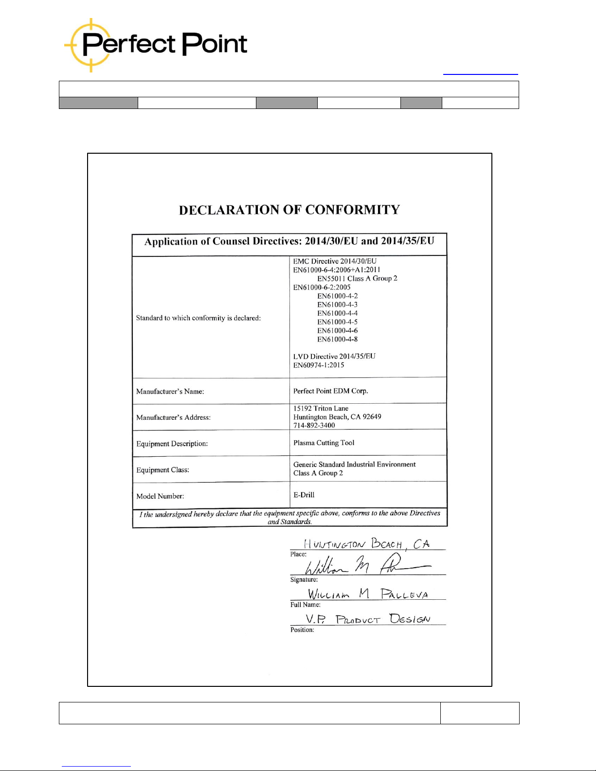
CE Declaration of Conformity:
Page 10
15192 Triton Lane
Huntington Beach, CA 92649
Office Tel: 714-892-3400
Hotline Tel: 714-891-6533
www.ppedm.com
User Guide
Document No.
61-101
Revision:
107
Date:
10/18/2018
This document is the property of PPedm Corp. and contains proprietary and/or patented information and may not be reproduced in
part or in whole without the express written permission of the company. Perfect Point logo, Perfect Point
TM
and E-Drill
®
are
trademarks of PPedm, Corp. US and worldwide patents pending.
Page 10 of 76
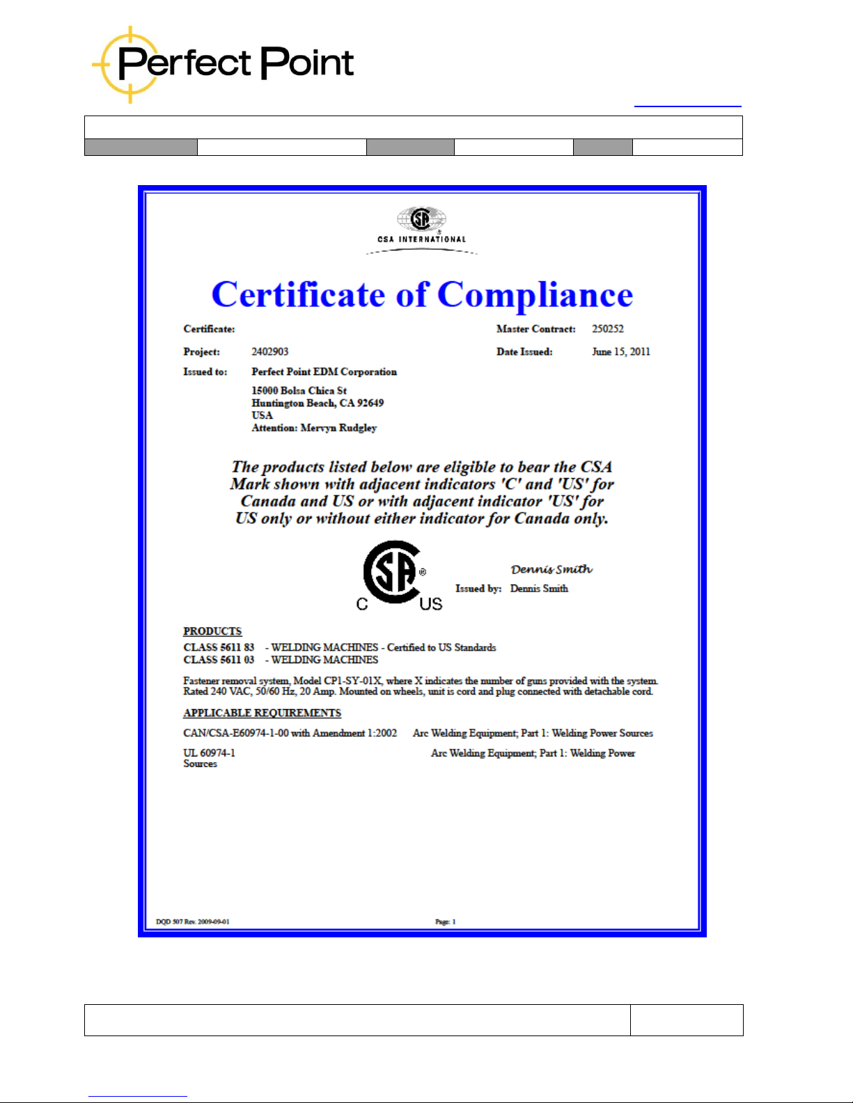
CSA Certificate of Compliance:
Page 11
15192 Triton Lane
Huntington Beach, CA 92649
Office Tel: 714-892-3400
Hotline Tel: 714-891-6533
www.ppedm.com
User Guide
Document No.
61-101
Revision:
107
Date:
10/18/2018
This document is the property of PPedm Corp. and contains proprietary and/or patented information and may not be reproduced in
part or in whole without the express written permission of the company. Perfect Point logo, Perfect Point
TM
and E-Drill
®
are
trademarks of PPedm, Corp. US and worldwide patents pending.
Page 11 of 76
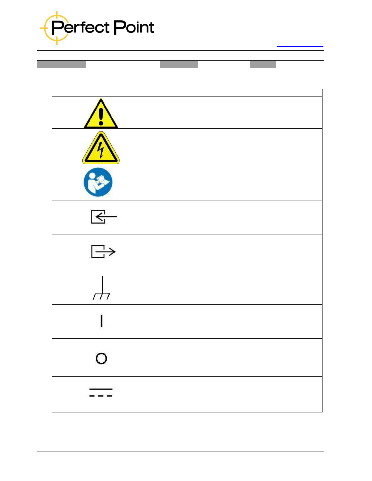
Description of Symbols Used in Product Labeling:
Symbol
Publication
Description
IEC 348
Attention, consult
accompanying
documents
IEC 417-5036
Dangerous voltage
ANSI Z535.4–2007
Read and understand manual before
operation
IEC70794
Input
IEC70795
Output
IEC5020
Chassis Ground
IEC5007
ON Power
IEC5008
OFF Power
IEC5031
Direct Current (DC)
Page 12

15192 Triton Lane
Huntington Beach, CA 92649
Office Tel: 714-892-3400
Hotline Tel: 714-891-6533
www.ppedm.com
User Guide
Document No.
61-101
Revision:
107
Date:
10/18/2018
This document is the property of PPedm Corp. and contains proprietary and/or patented information and may not be reproduced in
part or in whole without the express written permission of the company. Perfect Point logo, Perfect Point
TM
and E-Drill
®
are
trademarks of PPedm, Corp. US and worldwide patents pending.
Page 12 of 76
1.0
PRODUCT OVERVIEW:
1.1
Major Components:
The E-Drill system comprises; the Touch-Screen Display, Mounting Post and Cable
assembly, the Hand Tool and Umbilical Cable assembly, and the Mobile Service Unit
control cabinet. Various Tool Adapters, Electrodes and Accessories are supplied for
removal of specific fastener configurations and materials.
1.2
Technical Specifications:
Fastener Sizes: CG Hand tool - 5/32”–3/8”, inc. oversize’s
EG Hand Tool – 3/32”-1/4”, inc. oversize’s
Fastener Material: Aluminum, Titanium, Stainless Steel,
Alloy Steel, Inconel, Monel etc.
E-Drill Hand Tool Dimensions (approx.): 7.5” x 5” x 2”, 1.5 lb. (plus 10 ft. or 30 ft.
umbilical)
Mobile Service Unit Dimensions: 26” x 56” x 18”, 175 lb.
(including Toolbox & Adapter Kit)
Umbilical Extension: 20 ft. long (optional extra)
System Power Cable Assembly: 12 AWG, L6-20P Twist-lock Plug (except
Europe), 25 ft. long
* Facility Power Requirements: 220/240VAC, Single Phase, 20 Amp, 50/60
Hz, L6-20 Twist-lock Receptacle Plug
(except Europe)
Maximum Duty Cycle: 30 fasteners, or as many as possible with
one electrode (whichever is the least), at the
rate of 3 fasteners/minute (totaling 10
minutes). 1-minute minimum recovery time.
1.3
Operating Principle:
Conventionally fasteners are removed by drilling out the head of the fastener with a
hand drill and twist drill bit. This process is slow, requires significant strength from the
operator, generates Foreign Object Debris (FOD), and frequently results in damage
to the airframe.
The Perfect Point E-Drill system is a hand-held Electrical Discharge Machining (EDM)
tool designed to aid in the removal of hard airframe fasteners. The E-Drill device
weakens the fastener by electrically eroding a circular groove through the fastener
Page 13
15192 Triton Lane
Huntington Beach, CA 92649
Office Tel: 714-892-3400
Hotline Tel: 714-891-6533
www.ppedm.com
User Guide
Document No.
61-101
Revision:
107
Date:
10/18/2018
This document is the property of PPedm Corp. and contains proprietary and/or patented information and may not be reproduced in
part or in whole without the express written permission of the company. Perfect Point logo, Perfect Point
TM
and E-Drill
®
are
trademarks of PPedm, Corp. US and worldwide patents pending.
Page 13 of 76
head and a short distance into the stem (or pin) of the aircraft fastener. During cutting,
a closed loop de-ionized water system is used as a Dielectric Fluid and circulated
throughout the head of the device, in such a manner that the fastener and surrounding
airframe do not heat up and are cold to the touch immediately after cutting.
The depth of cutting is controlled automatically, such that a thin wall remains holding
the fastener head in place. The fastener head may then easily be severed by a sharp
tap with a hammer and hand punch. When the device is positioned correctly the
airframe is not damaged in any way, and the temperature rise in the airframe around
the hole is insignificant. Due to the depth of the cut, the fastener stem has no remnant
burr which may damage the hole in the airframe as the stem is driven out.
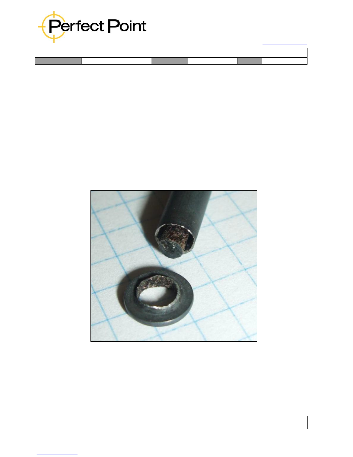
The photograph below shows a severed fastener with the groove and the fractured
thin wall. Note that the cut is concentric with the stem; the wall thickness is uniform
around the pin, the cut ends just below the head, and the fastener stem is burr free.
Page 14
15192 Triton Lane
Huntington Beach, CA 92649
Office Tel: 714-892-3400
Hotline Tel: 714-891-6533
www.ppedm.com
User Guide
Document No.
61-101
Revision:
107
Date:
10/18/2018
This document is the property of PPedm Corp. and contains proprietary and/or patented information and may not be reproduced in
part or in whole without the express written permission of the company. Perfect Point logo, Perfect Point
TM
and E-Drill
®
are
trademarks of PPedm, Corp. US and worldwide patents pending.
Page 14 of 76
1.4
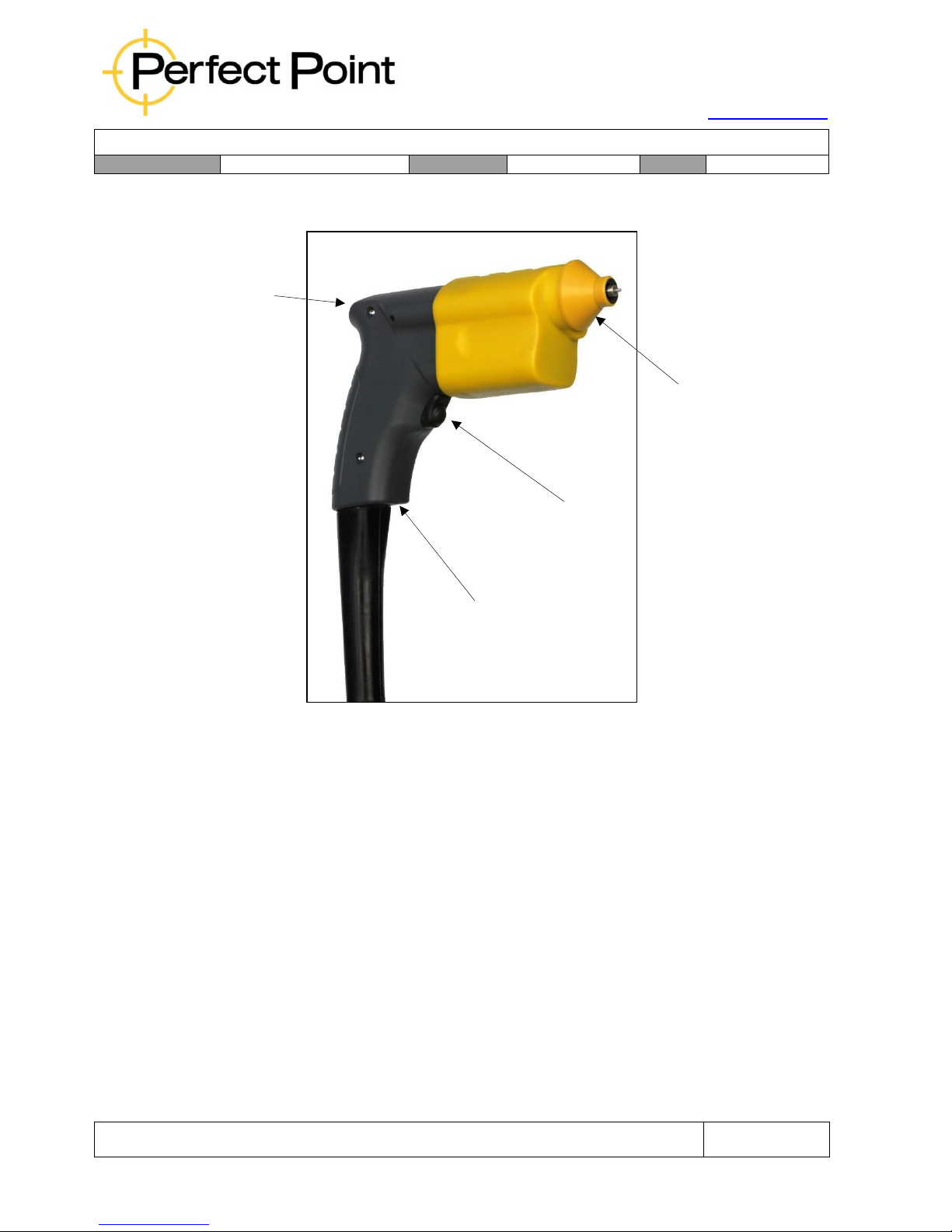
E-Drill Hand Tool General Features and Controls:
E-Drill Hand Tool
Interchangeable Adapters:
The E-Drill includes a kit of Interchangeable Adapters suitable for different fastener
types and removal processes. Depending on which size E-Drill Hand Tool has been
purchased, the Adapter kit may be one of two types (systems provided with both size
of Hand Tool automatically includes both Adapter kits):
•
EG Adapter Kit – comprises button head and flush head Adapters and
locators for 1/8” and 5/32” diameter fasteners.
•
CG Adapter Kit – comprises button head and flush head Adapters and
locators for 3/16” and 1/4” diameter fasteners.
Adapters and locators are intentionally manufactured in plastic using brighter colors,
so they may be easier to find if dropped or mislaid. This is helpful in all shop
environments, but especially in FOD-controlled situations. The plastic also reduces
the chance of marring the airframe surface.
Status Light
Interchangeable
Adapter
Trigger
Retract
Button
Page 15

15192 Triton Lane
Huntington Beach, CA 92649
Office Tel: 714-892-3400
Hotline Tel: 714-891-6533
www.ppedm.com
User Guide
Document No.
61-101
Revision:
107
Date:
10/18/2018
This document is the property of PPedm Corp. and contains proprietary and/or patented information and may not be reproduced in
part or in whole without the express written permission of the company. Perfect Point logo, Perfect Point
TM
and E-Drill
®
are
trademarks of PPedm, Corp. US and worldwide patents pending.
Page 15 of 76
*Note: Since the range of fasteners in the aerospace industry is so large, it is not
possible to provide Adapters for all types of protruding head fasteners that EDrill supports in the base product. Therefore prior to purchase of a system,
please provide a list of button-head fasteners which you intend to use the EDrill with. Additional or custom Adapters are available on request.
Trigger:
The trigger is depressed to initiate the cutting process, and is held depressed until the
cut automatically completes. As a safety feature, should the trigger be released, the
cutting process will be aborted immediately. Keeping the trigger depressed after the
cut is finished will assist in cleanup of any excess water which may remain after
cutting.
Retract Button:
The Retract Button recessed in the handle is used when necessary to retract the
cutting electrode. Typically, the retract button is only used when:
a)
A new electrode has been installed and needs to be retracted, or …
b)
When the trigger has been operated accidentally when not placed on a
fastener and the electrode has moved forward as a result, or …
c)
When the E-Drill has been applied to a non-conductive surface and the
electrode has extended in search of a conductive material.
The electrode retracts continuously while the button is held down. Retraction stops
when the button is released, or the device reaches the retract limit.
Status Light:
The Status Light communicates various conditions during operation as follows:
•
Solid Green light upon cut completion – Cut was successfully completed.
•
Solid Green while operating the retract button – Electrode is fully retracted.
•
Flashing Green upon cut completion – Cut was completed successfully but
the electrode needs replacement before next cut. The system is disabled
until electrode has been replaced and fully retracted.
•
Solid Red upon cut completion – Cut was completed with errors. Either the
trigger was released before reaching depth, or the cut took excessively long.
Which condition occurred will be reported by the Touch-Screen Display.
Likely issues causing slow cutting are either (a) the head of fastener was not
Page 16
15192 Triton Lane
Huntington Beach, CA 92649
Office Tel: 714-892-3400
Hotline Tel: 714-891-6533
www.ppedm.com
User Guide
Document No.
61-101
Revision:
107
Date:
10/18/2018
This document is the property of PPedm Corp. and contains proprietary and/or patented information and may not be reproduced in
part or in whole without the express written permission of the company. Perfect Point logo, Perfect Point
TM
and E-Drill
®
are
trademarks of PPedm, Corp. US and worldwide patents pending.
Page 16 of 76
de-painted adequately, or b) wrong fastener type was programmed on the
hand terminal, or c) the electrode is loose.
•
Flashing Red (at any time) – An error has been identified, system is disabled.
System error will be displayed on the Touch-Screen Display. Typically, the
flashing red indicates a low water level, and a Top-Off needs to be performed.
The system is disabled until the water level is restored.
Note: Solid lights are informational - The unit is still operational. Flashing Lights
require user intervention - Unit is disabled until the condition is resolved.
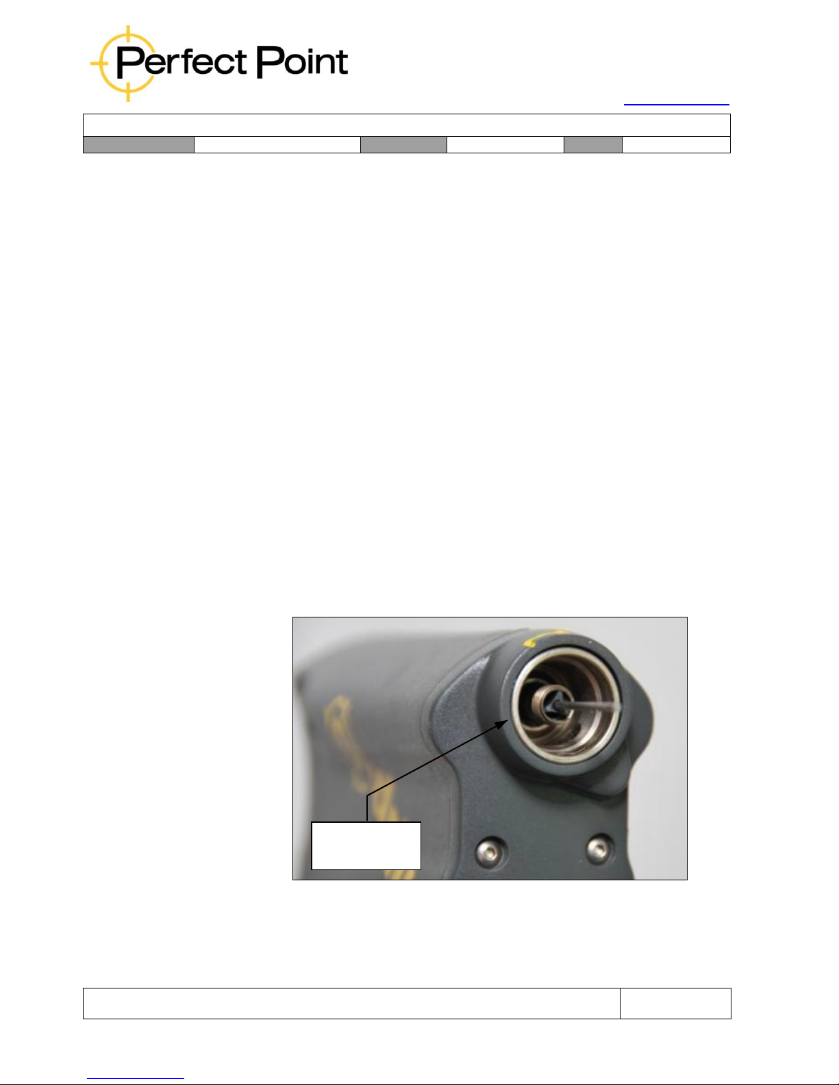
1.4.1
E-Drill Hand Tool Configurations:
E-Drill Hand Tools are currently provided in two different configurations to
cover a wide spectrum of fastener sizes commonly encountered. Each Hand
Tool has specific fastener size capabilities and features. This User Guide
covers the use of all standard types of E-Drill hand tools.
Each hand tool configuration uses a specific set of adapters that are
described and identified throughout the sections of this user guide. The
adapters are used for a specific set of electrode sizes with that particular hand
tool configuration. Adapters for some older hand tools use a different
mounting method (Bayonet vs. Tri-Wing) so Adapters for a newer system may
not fit the older system.
Bayonet Nose
Hand Tool
Page 17
15192 Triton Lane
Huntington Beach, CA 92649
Office Tel: 714-892-3400
Hotline Tel: 714-891-6533
www.ppedm.com
User Guide
Document No.
61-101
Revision:
107
Date:
10/18/2018
This document is the property of PPedm Corp. and contains proprietary and/or patented information and may not be reproduced in
part or in whole without the express written permission of the company. Perfect Point logo, Perfect Point
TM
and E-Drill
®
are
trademarks of PPedm, Corp. US and worldwide patents pending.
Page 17 of 76
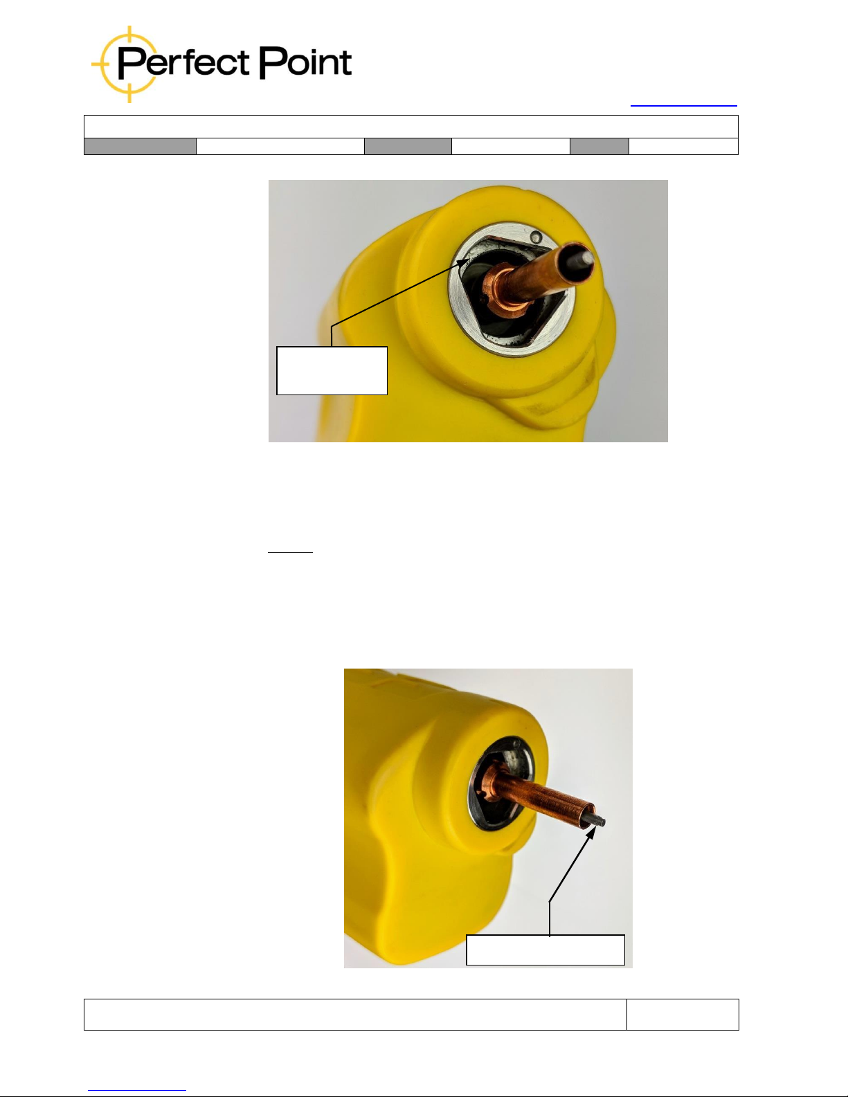
1.4.2
Center Ground (CG) E-Drill Hand Tool, Part No. CP1-CED-010:
This hand tool configuration is capable of removing fasteners from 5/32”
Nominal Stem Size (-5) through 3/8”, including oversize’s. For fasteners
smaller than these sizes the External Ground (EG) E-Drill Hand Tool should
be used.
This CG hand tool is Center Grounded by means of a Ground Pin that
protrudes through the center of the cutting electrode. Hand tool visual
identification can be quickly made by inspecting the nose of the hand tool. If
the Ground Pin is visible protruding from the center of the electrode, then this
is a CG or Center Ground Hand Tool.
Tri-Wing Nose
Hand Tool
Protruding Ground Pin
Page 18
15192 Triton Lane
Huntington Beach, CA 92649
Office Tel: 714-892-3400
Hotline Tel: 714-891-6533
www.ppedm.com
User Guide
Document No.
61-101
Revision:
107
Date:
10/18/2018
This document is the property of PPedm Corp. and contains proprietary and/or patented information and may not be reproduced in
part or in whole without the express written permission of the company. Perfect Point logo, Perfect Point
TM
and E-Drill
®
are
trademarks of PPedm, Corp. US and worldwide patents pending.
Page 18 of 76
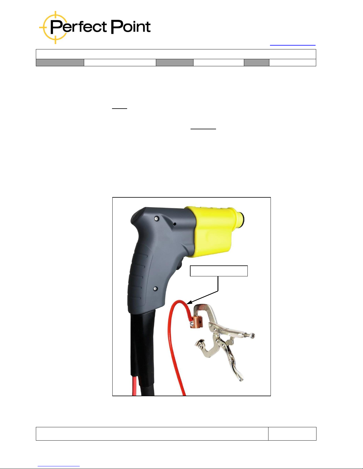
1.4.3
External Ground (EG) E-Drill Hand Tool, Part No. CP1-CED-020:
This hand tool configuration is capable of removing fasteners from 3/32”
Nominal Stem Size (-3) through 1/4”, including oversize’s. For fasteners
larger than these sizes the Center Ground (CG) E-Drill Hand Tool should be
used.
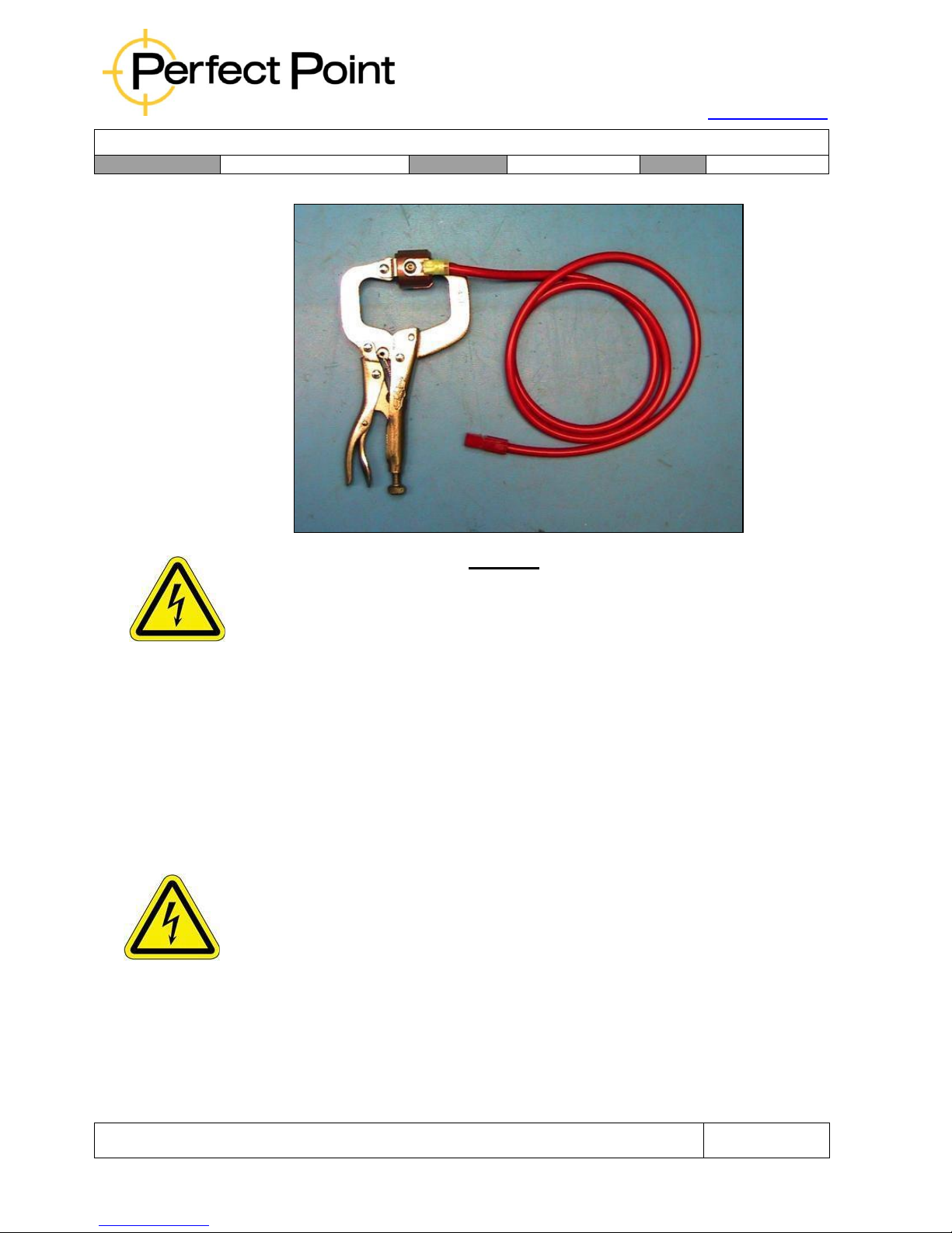
The EG E-Drill Hand Tool is externally grounded by means of an External
Ground lead and clamp. The Hand Tool Ground Lead and Grounding Clamp
Assembly have a “break away” safety connector feature for operator safety
and to prevent accidental cable breakage.
Hand tool visual identification can be made by inspecting the nose of the hand
tool and its cable strain relief. The hand tool lacks a Ground Pin leaving the
smaller electrode open for greater fluid flow. The hand tool cable strain relief
has a Red Ground Cable Lead and Connector allowing for connection of the
Ground Clamp Assembly Part No. EDT0301.
External Ground
Page 19
15192 Triton Lane
Huntington Beach, CA 92649
Office Tel: 714-892-3400
Hotline Tel: 714-891-6533
www.ppedm.com
User Guide
Document No.
61-101
Revision:
107
Date:
10/18/2018
This document is the property of PPedm Corp. and contains proprietary and/or patented information and may not be reproduced in
part or in whole without the express written permission of the company. Perfect Point logo, Perfect Point
TM
and E-Drill
®
are
trademarks of PPedm, Corp. US and worldwide patents pending.
Page 19 of 76
CAUTION
The External Ground (EG) Hand Tool will NOT operate without the system properly
grounded by the Ground Clamp Assembly. Check for electrical ground prior to further
system trouble shooting.
1.5 Mobile Service Unit Features, Controls, and Connections:
The Mobile Service Unit comprises the following primary components
1.5.1
Work Area:
The top of the Mobile Service Unit presents a flat area onto which the included
lockable toolbox rests, and a small work area to collect fastener remnants or
small hand tools. There is also a handle with which the unit can be moved
around.
WARNING
The Mobile Service Unit handle should not be used as a means of lifting the unit.
The toolbox may be removed and placed near the work area if desired. Inside the
hinged lid of the toolbox is a quick-start guide which describes operation of the
system.
Page 20

15192 Triton Lane
Huntington Beach, CA 92649
Office Tel: 714-892-3400
Hotline Tel: 714-891-6533
www.ppedm.com
User Guide
Document No.
61-101
Revision:
107
Date:
10/18/2018
This document is the property of PPedm Corp. and contains proprietary and/or patented information and may not be reproduced in
part or in whole without the express written permission of the company. Perfect Point logo, Perfect Point
TM
and E-Drill
®
are
trademarks of PPedm, Corp. US and worldwide patents pending.
Page 20 of 76
1.5.2
Dielectric System:
The service unit includes a re-circulating dielectric fluid filtration and reconditioning
system. This system requires regular service, as detailed in section 3.
1.5.3
Touch-Screen Display:
The Touch-Screen Display (TSD) provides an interface through which the user can
select different fastener types to remove (as described in Section 2) and carry out
maintenance functions (as described in Section 3). The TSD also displays status
information including:
•
Current fastener setting
•
Cut time for last cut
•
Current system status or error messages
TSD operation is listed in more detail in Section 2.
Page 21
15192 Triton Lane
Huntington Beach, CA 92649
Office Tel: 714-892-3400
Hotline Tel: 714-891-6533
www.ppedm.com
User Guide
Document No.
61-101
Revision:
107
Date:
10/18/2018
This document is the property of PPedm Corp. and contains proprietary and/or patented information and may not be reproduced in
part or in whole without the express written permission of the company. Perfect Point logo, Perfect Point
TM
and E-Drill
®
are
trademarks of PPedm, Corp. US and worldwide patents pending.
Page 21 of 76
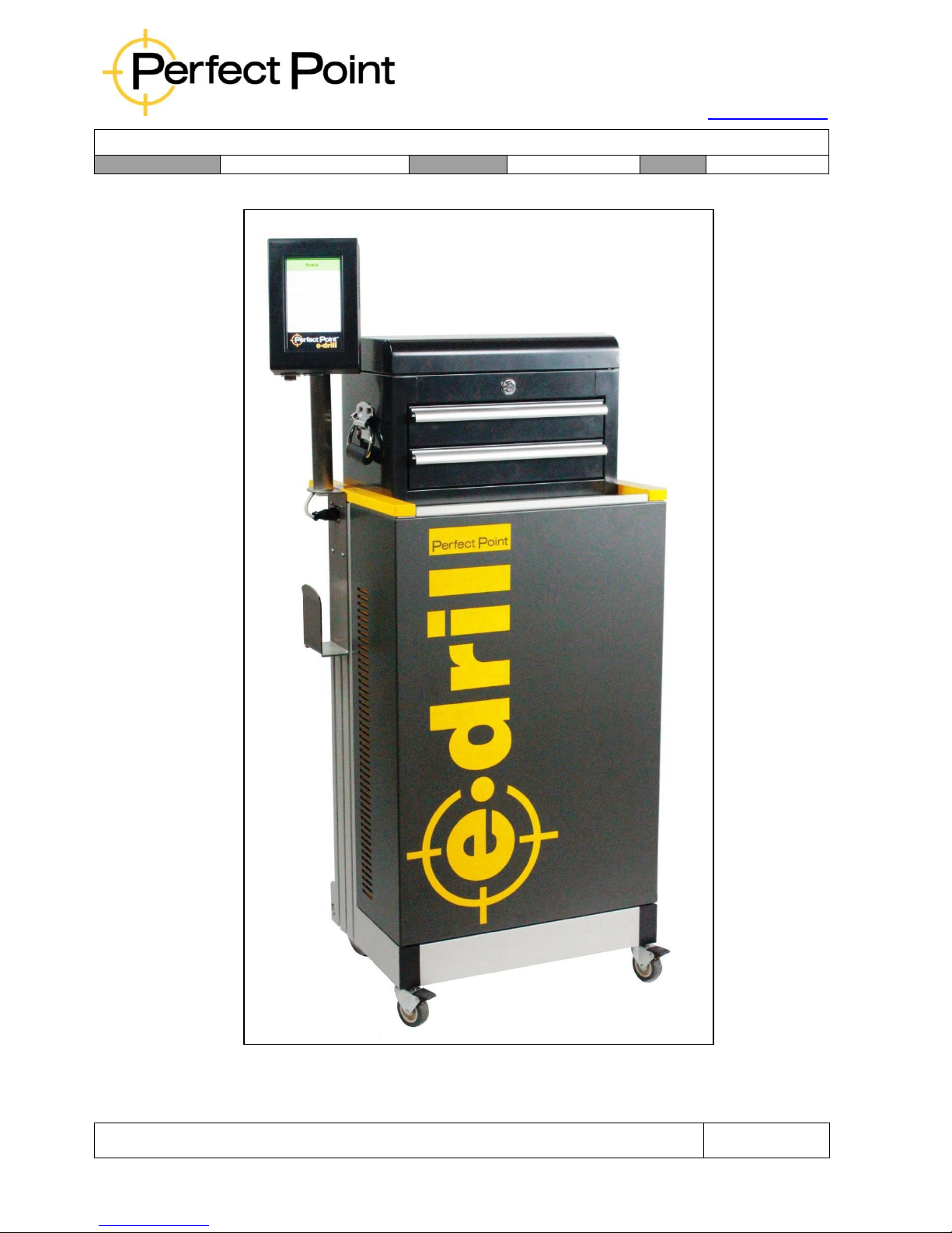
Mobile Service Unit - Front View
(CP1-SY-151 has a separate tool-cart instead of the toolbox)
Page 22
15192 Triton Lane
Huntington Beach, CA 92649
Office Tel: 714-892-3400
Hotline Tel: 714-891-6533
www.ppedm.com
User Guide
Document No.
61-101
Revision:
107
Date:
10/18/2018
This document is the property of PPedm Corp. and contains proprietary and/or patented information and may not be reproduced in
part or in whole without the express written permission of the company. Perfect Point logo, Perfect Point
TM
and E-Drill
®
are
trademarks of PPedm, Corp. US and worldwide patents pending.
Page 22 of 76
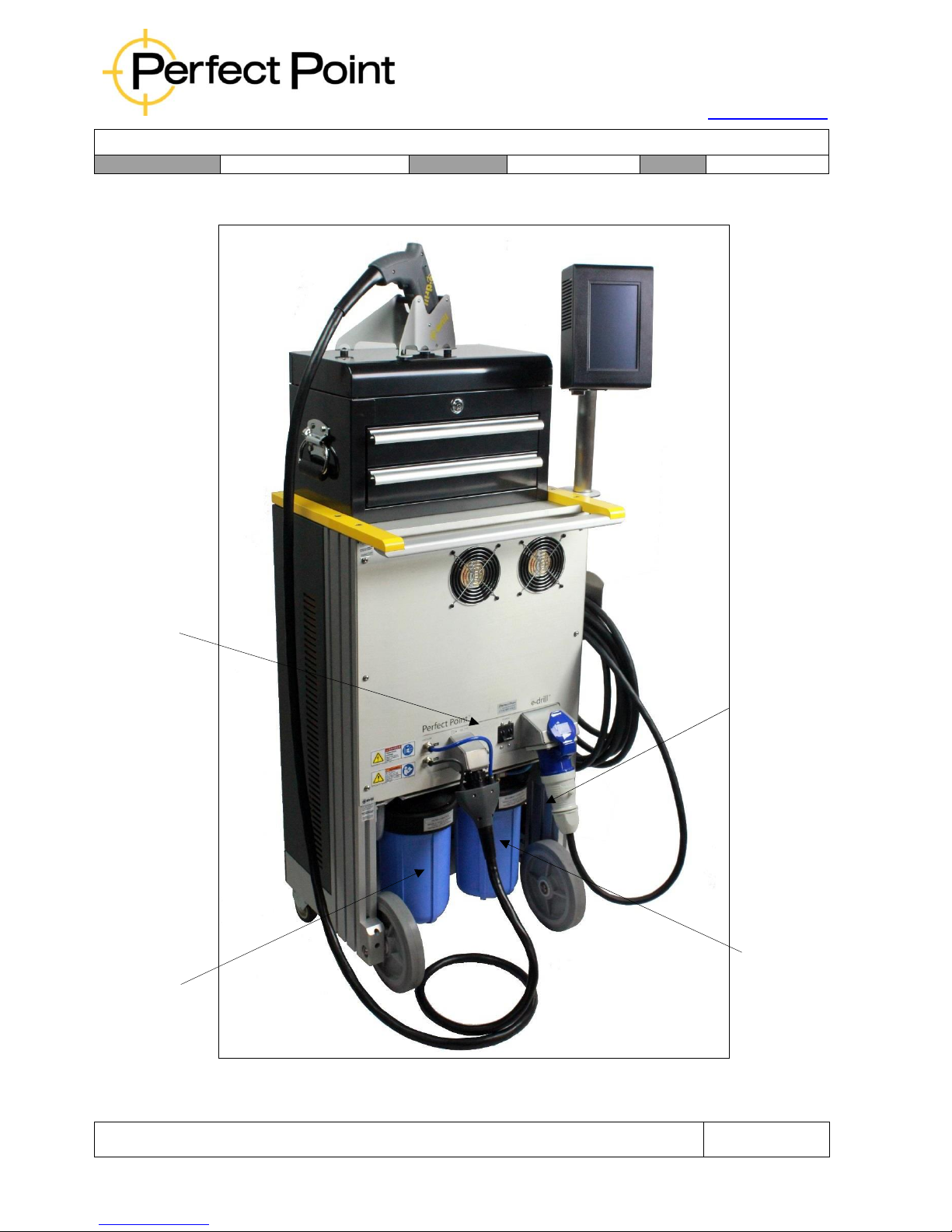
Connection
Panel
Dielectric
Filter
Assembly
Lock-Bolt
Sediment
Bowl
Particulate
Filter Bowl
Mobile Service Unit - Rear View
(CP1-SY-151 has a separate tool-cart instead of the toolbox)
Page 23
15192 Triton Lane
Huntington Beach, CA 92649
Office Tel: 714-892-3400
Hotline Tel: 714-891-6533
www.ppedm.com
User Guide
Document No.
61-101
Revision:
107
Date:
10/18/2018
This document is the property of PPedm Corp. and contains proprietary and/or patented information and may not be reproduced in
part or in whole without the express written permission of the company. Perfect Point logo, Perfect Point
TM
and E-Drill
®
are
trademarks of PPedm, Corp. US and worldwide patents pending.
Page 23 of 76
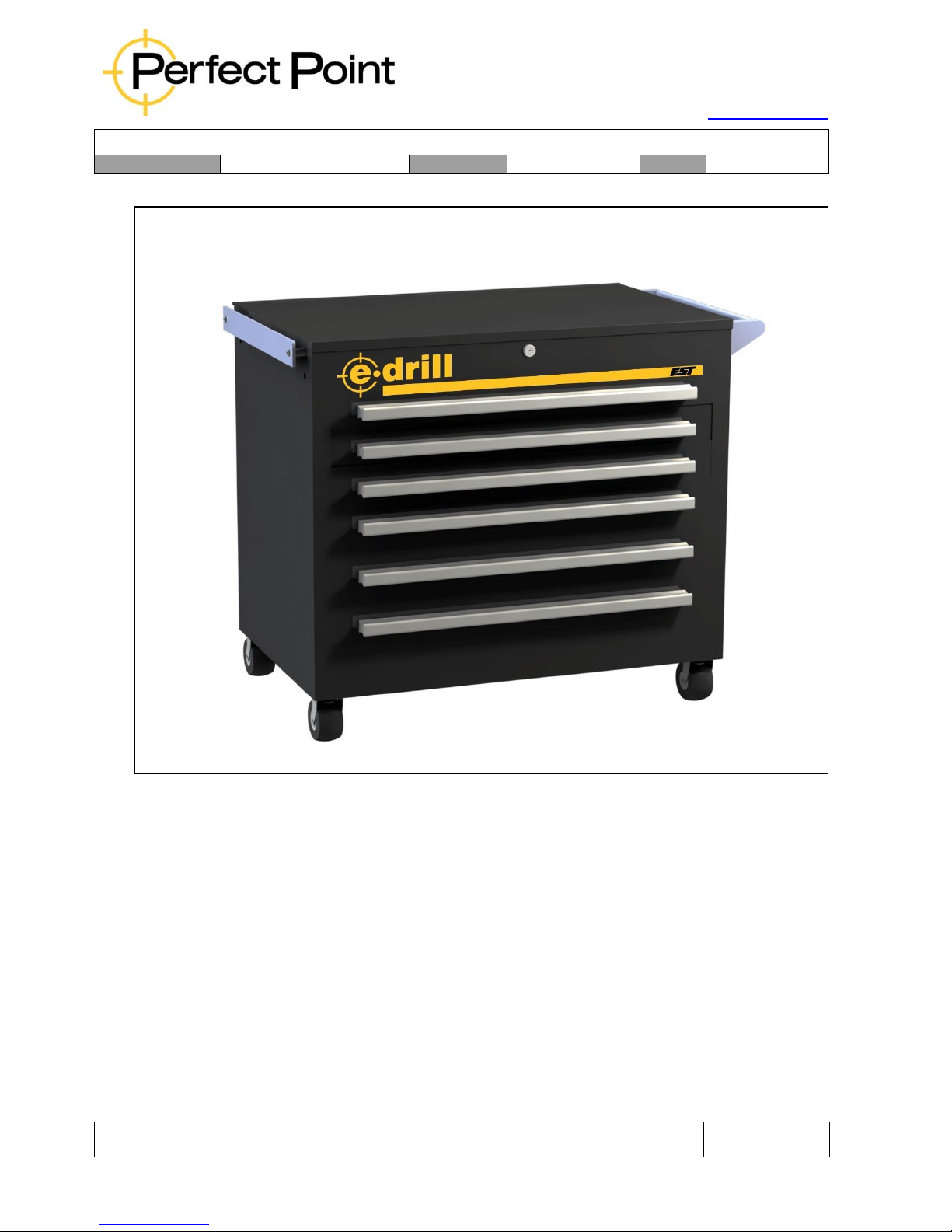
CP1-SY-151 separate tool-cart
(also available as p/n’s EDT0406 Professional Complete & EDT0405 Empty)
Page 24
15192 Triton Lane
Huntington Beach, CA 92649
Office Tel: 714-892-3400
Hotline Tel: 714-891-6533
www.ppedm.com
User Guide
Document No.
61-101
Revision:
107
Date:
10/18/2018
This document is the property of PPedm Corp. and contains proprietary and/or patented information and may not be reproduced in
part or in whole without the express written permission of the company. Perfect Point logo, Perfect Point
TM
and E-Drill
®
are
trademarks of PPedm, Corp. US and worldwide patents pending.
Page 24 of 76
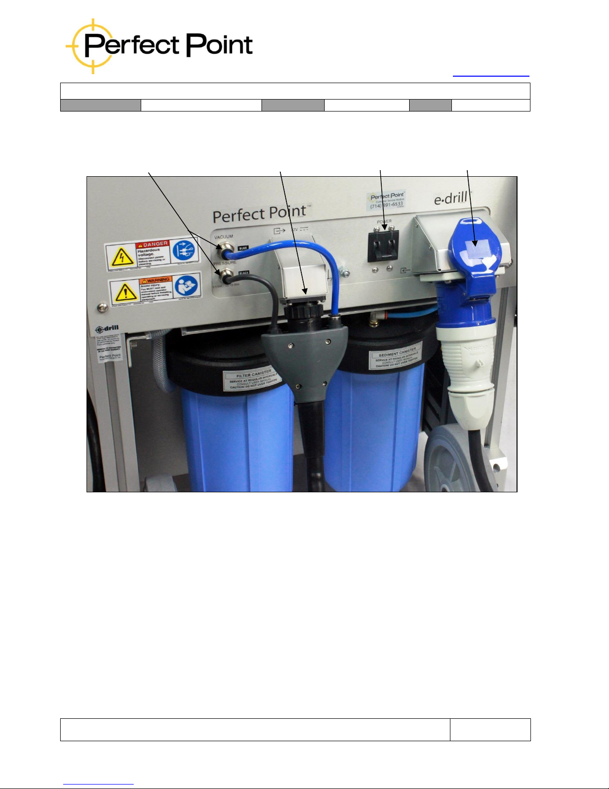
Mobile Service Unit – Rear Connections
Connection of the various components together is self-evident. However certain key
points should be noted:
1.
The hand-tool connector installs in one vertical orientation, with the blue
Vacuum dielectric connector at the top, and the black Pressure dielectric
connector at the bottom (matching the cabinet connections). The black
electrical connector locking bezel must be twisted until a definite click is felt.
The Touch-Screen Display connection (on the side of the unit at the top) also
installs in only one orientation and includes a locking bezel.
2.
When removing the hand-tool, the bezels around the Push-To-Connect™
fluid fittings on the Mobile Service Unit and Umbilical Cable must be pushed
in to release the tubes.
Dielectric Vacuum (upper) and
Pressure (lower) Connections
E-Drill Hand-Tool
Electrical Connection
Power Switch
Single-Phase
Electrical Connection
Page 25
15192 Triton Lane
Huntington Beach, CA 92649
Office Tel: 714-892-3400
Hotline Tel: 714-891-6533
www.ppedm.com
User Guide
Document No.
61-101
Revision:
107
Date:
10/18/2018
This document is the property of PPedm Corp. and contains proprietary and/or patented information and may not be reproduced in
part or in whole without the express written permission of the company. Perfect Point logo, Perfect Point
TM
and E-Drill
®
are
trademarks of PPedm, Corp. US and worldwide patents pending.
Page 25 of 76
3.
When installing the hand-tool, the tubes should be pushed into the push-toconnect fittings and then lightly pulled such that they are “set”.
4.
After installing or re-installing a hand-tool or installing the umbilical extension,
it is good practice to bleed the pressure line to the hand-tool (see Section 3.7
for system bleeding and charging instructions).
Warning
Under no circumstances should the electrical connectors be forced. If aligned correctly,
minimal force is required. Excessive force will Damage the connectors, and will not be
covered under warranty.
1.6 Touch-Screen Display Command Screens:
The Touch-Screen Display (TSD) is the device through which fastener types are
selected and maintenance activities are performed. There are four primary screens
on the control terminal (contents of each screen may change slightly by customer):
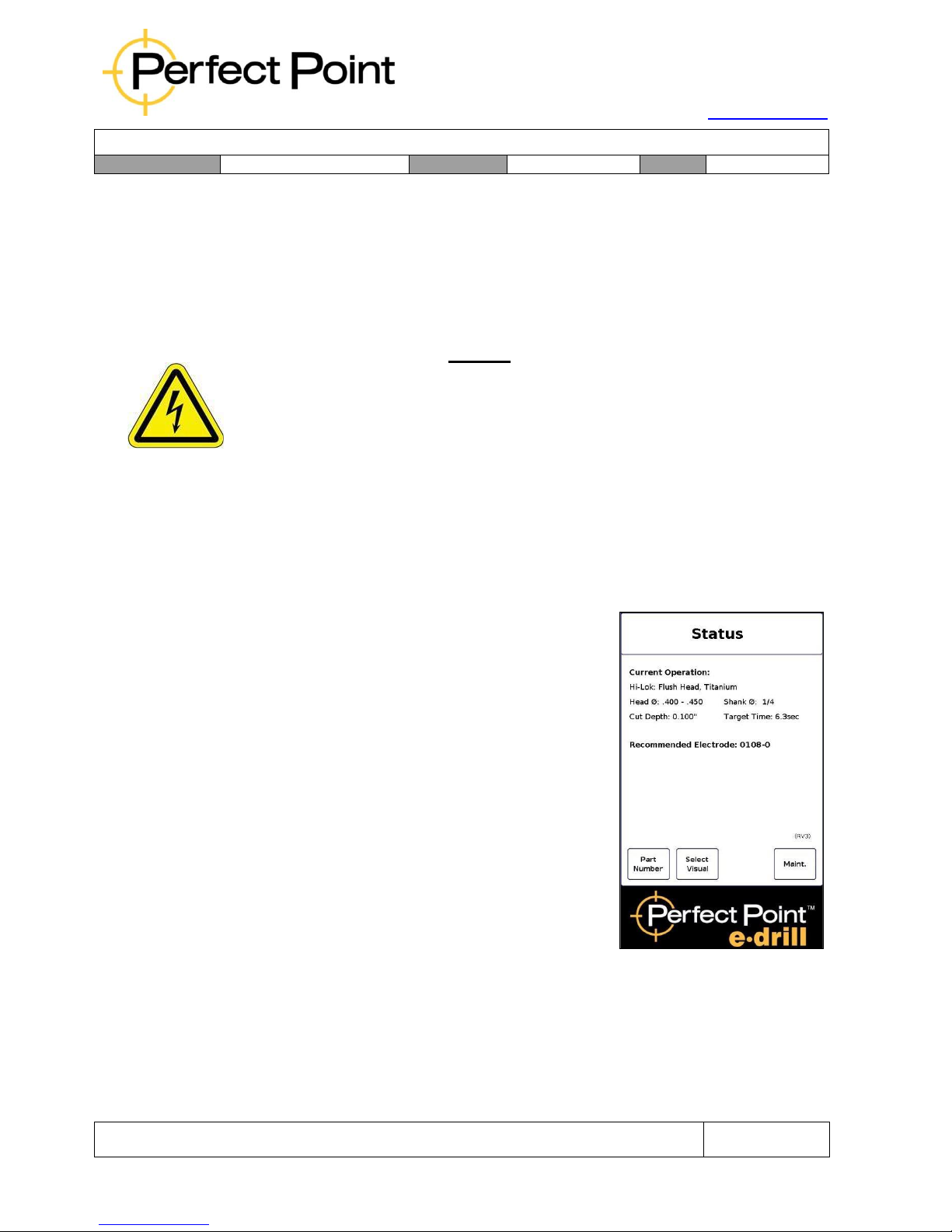
A)
Home Screen – displays the current
fastener selected, and the Electrode size
and type which should be used.
Page 26
15192 Triton Lane
Huntington Beach, CA 92649
Office Tel: 714-892-3400
Hotline Tel: 714-891-6533
www.ppedm.com
User Guide
Document No.
61-101
Revision:
107
Date:
10/18/2018
This document is the property of PPedm Corp. and contains proprietary and/or patented information and may not be reproduced in
part or in whole without the express written permission of the company. Perfect Point logo, Perfect Point
TM
and E-Drill
®
are
trademarks of PPedm, Corp. US and worldwide patents pending.
Page 26 of 76
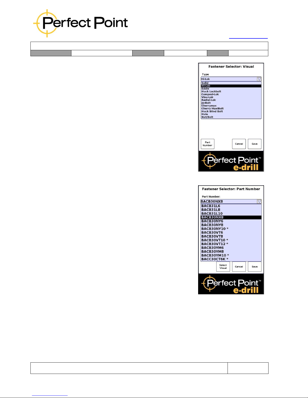
B)
Fastener Visual Selector Screen –
provides options to select a particular
fastener by its physical characteristics;
comprising type of fastener, removal method
(flush, button, collar), fastener material, head
diameter ranges and stem diameter. (This
screen may be disabled by customer
preference in some installations.)
C)
Part Number Selector Screen – enables
quick selection of a fastener by part number.
Typically the menu of available part numbers
is localized for the customer and project. The
option is provided to switch between Visual
Selector screen and Part Number Selector
screen.
Page 27
15192 Triton Lane
Huntington Beach, CA 92649
Office Tel: 714-892-3400
Hotline Tel: 714-891-6533
www.ppedm.com
User Guide
Document No.
61-101
Revision:
107
Date:
10/18/2018
This document is the property of PPedm Corp. and contains proprietary and/or patented information and may not be reproduced in
part or in whole without the express written permission of the company. Perfect Point logo, Perfect Point
TM
and E-Drill
®
are
trademarks of PPedm, Corp. US and worldwide patents pending.
Page 27 of 76
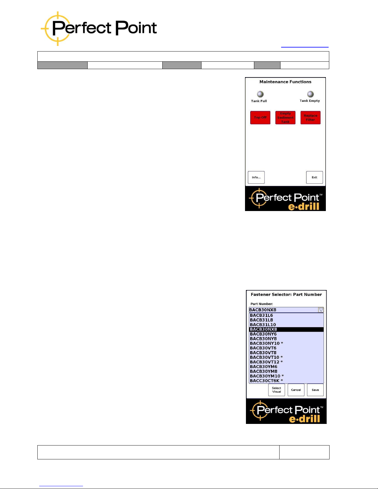
D)
Maintenance Screen – provides options to
Top Off the de-ionized water system, empty
the Sediment Tank, or drain the system
completely (for filter replacement – see
Section 3).
E)
All screens display the screen name along
the top. The Home screen displays the
Perfect Point E-Drill title, below which is the
Status screen which communicates cut
time, warnings and errors.
2.0
OPERATION:
2.1
Using the Part Number Selector:
Setup for removal of any type of fastener may be carried out by one of two methods;
either by using the Part Number Selector or by using the Visual Selector (if available).
Either method may be used, or the user may switch between them at any time.
However, they are not interdependent, so the user cannot for example select Type in
the Visual Selector menu and then switch to the Part Number Selector and see a subset of part numbers of that type.
To use the Part Number Selector:
Press Part Number on the home screen.
1.
Highlight the Part Number window, scroll
down to the correct part number and select
it by pressing it.
2.
Hit Save to select that part number and
load parameters from the library.
Page 28
15192 Triton Lane
Huntington Beach, CA 92649
Office Tel: 714-892-3400
Hotline Tel: 714-891-6533
www.ppedm.com
User Guide
Document No.
61-101
Revision:
107
Date:
10/18/2018
This document is the property of PPedm Corp. and contains proprietary and/or patented information and may not be reproduced in
part or in whole without the express written permission of the company. Perfect Point logo, Perfect Point
TM
and E-Drill
®
are
trademarks of PPedm, Corp. US and worldwide patents pending.
Page 28 of 76
2.2
Using the Visual Selector:
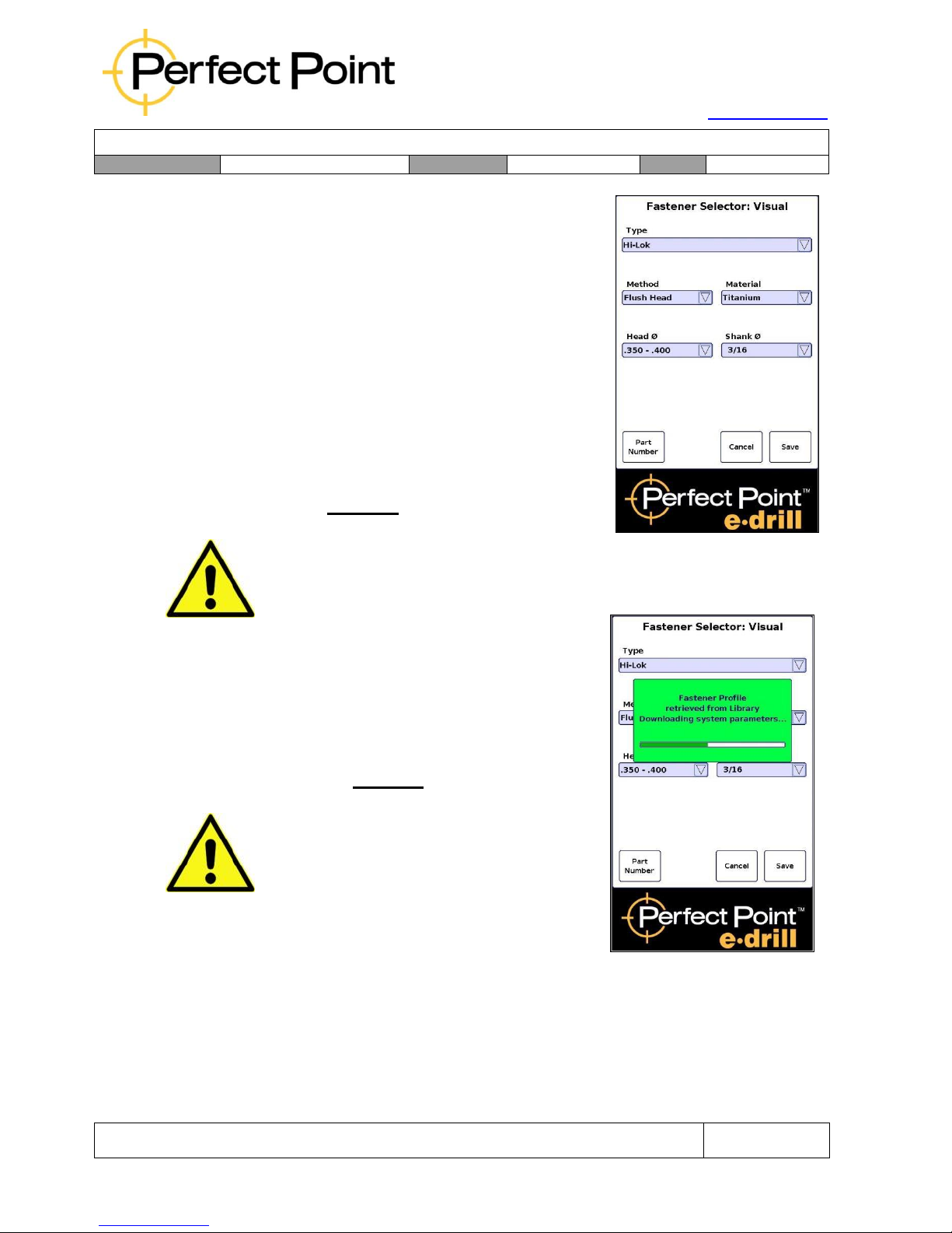
1.
Press Select Visual on the home screen.
2.
Progressing down the screen from top to
bottom and left to right, in order highlight
and select Type, Method, Material, Head (or
collar) Diameter range, and Stem Size. The
system will automatically offer a default
Stem Size, but the default selection should
always be checked before Saving.
3.
Hit Save to accept the selection and load
parameters from library.
CAUTION
Once the other 4 parameters are selected, the system will automatically suggest
the Stem Size. It is critical that the user check that the suggestion is correct,
since for certain shear head fasteners the suggestion may be incorrect.
Whichever selection mode is chosen (Part Number
or Visual), once the Save button is pressed; the
system will select the correct cutting and depth
control parameters and download them from the
library. Progress in loading parameters will be shown
in a green panel (as shown left).
CAUTION
Since not all possible combinations may be in
the fastener library, it is possible to pick a
combination for which there is not a library
entry. If that occurs, a Red panel will appear
indicating that a library entry has not been
found, and the user should re-select. When this
occurs, the user should check the default
values to ensure they will work or recheck their
selection.
Before cutting, it is necessary to remove paint (or any other insulating layer) from the
head of fasteners to be removed, so that electrical conductivity to the head of the
fastener is ensured. Since the surrounding surface is also used to seal in the Dielectric
Water, rough surfaces around the fastener head should also be cleaned of any debris
or smoothed by covering with tape.
Page 29
15192 Triton Lane
Huntington Beach, CA 92649
Office Tel: 714-892-3400
Hotline Tel: 714-891-6533
www.ppedm.com
User Guide
Document No.
61-101
Revision:
107
Date:
10/18/2018
This document is the property of PPedm Corp. and contains proprietary and/or patented information and may not be reproduced in
part or in whole without the express written permission of the company. Perfect Point logo, Perfect Point
TM
and E-Drill
®
are
trademarks of PPedm, Corp. US and worldwide patents pending.
Page 29 of 76
Though it is not necessary for operation of the E-Drill system, it is strongly
recommended when using any electric device on the airframe to ensure the airframe
is grounded.
CAUTION
Before cutting you must ensure that the hand-tool is correctly configured – failure
to use the correct ADAPTER AND ELECTRODE could result in damage to the
airframe.
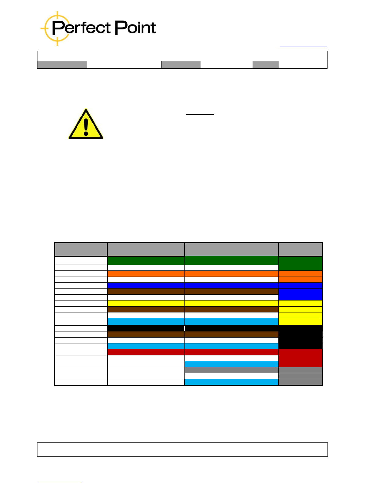
2.3
Cutting Electrode Sizes and Electrode Guide Color Matching:
There are 14 different standard Cutting Electrode O.D sizes available to cover 14
different diameter fasteners from 5/32” to 3/8”. Electrodes are designed to remove
nominal, X (1
st
Oversize) and Y (2
nd
Oversize) fasteners.
Cutting Electrodes are packaged with color coded inserts and provided in kits of 5
each to match their sizes. The E-Drill Electrode Guides to be used in the E-Drill
Adapters are color-coded to match. For convenience, each electrode is engraved with
its Electrode Part Number. The chart and color legend below illustrates the size color
coding.
Electrode
Size
BHL/ FHL Adapter
Electrode Guide
VFHL/ OVL Adapter Electrode Guide
Electrode
Packaging
3/32 Nominal
GREEN Electrode Guide
GREEN Electrode Guide
GREEN Cutout
3/32 Plus
WHITE Electrode Guide
WHITE Electrode Guide
GREEN Cutout
1/8 Nominal
ORANGE Electrode Guide
ORANGE Electrode Guide
ORANGE Cutout
1/8 Plus
WHITE Electrode Guide
WHITE Electrode Guide
ORANGE Cutout
5/32 Nominal
BLUE Electrode Guide
BLUE Electrode Guide
BLUE Cutout
5/32 Plus
BROWN Electrode Guide
BROWN Electrode Guide
BLUE Cutout
5/32 1
st
Oversize (X)
WHITE Electrode Guide
WHITE Electrode Guide
BLUE Cutout
3/16 Nominal
YELLOW Electrode Guide
YELLOW Electrode Guide
YELLOW Cutout
3/16 Plus
BROWN Electrode Guide
BROWN Electrode Guide
YELLOW Cutout
3/16 1
st
Oversize (X)
WHITE Electrode Guide
WHITE Electrode Guide
YELLOW Cutout
3/16 2
nd
Oversize (Y)
TURQUOISE Electrode Guide
TURQUOISE Electrode Guide
YELLOW Cutout
1/4 Nominal
BLACK Electrode Guide
BLACK Electrode Guide
BLACK Cutout
1/4 Plus
BROWN Electrode Guide
BROWN Electrode Guide
BLACK Cutout
1/4 1
st
Oversize (X)
WHITE Electrode Guide
WHITE Electrode Guide
BLACK Cutout
1/4 2
nd
Oversize (Y)
TURQUOISE Electrode Guide
TURQUOISE Electrode Guide
BLACK Cutout
5/16 Nominal
RED Electrode Guide
RED Electrode Guide
RED Cutout
5/16 1
st
Oversize (X)
WHITE Electrode Guide
WHITE Electrode Guide
RED Cutout
5/16 2
nd
Oversize (Y)
No Guide Required at this size
TURQUIOSE Electrode Guide
RED Cutout
3/8 Nominal
No Guide Required at this size
GREY Electrode Guide
GRAY Cutout
3/8 1
st
Oversize (X)
No Guide Required at this size
WHITE Electrode Guide
GRAY Cutout
3/8 2
nd
Oversize (Y)
No Guide Required at this size
TURQUIOSE Electrode Guide
GRAY Cutout
Note: Guides should be regularly inspected for damage or wear. Guides with heavy usage should
be replaced every 5000 cuts or when the electrode appears loose in the guide (see Display for Cut
Count).
Page 30
15192 Triton Lane
Huntington Beach, CA 92649
Office Tel: 714-892-3400
Hotline Tel: 714-891-6533
www.ppedm.com
User Guide
Document No.
61-101
Revision:
107
Date:
10/18/2018
This document is the property of PPedm Corp. and contains proprietary and/or patented information and may not be reproduced in
part or in whole without the express written permission of the company. Perfect Point logo, Perfect Point
TM
and E-Drill
®
are
trademarks of PPedm, Corp. US and worldwide patents pending.
Page 30 of 76
CAUTION
Failure to replace worn electrode guides will have an adverse effect on the ability of the
E-Drill to accurately locate the center of the fastener being cut. Failure to replace worn
Electrode guides may cause damage to surrounding airframe if not properly maintained.
2.4
Removal of Button-Head Fasteners:
The first step before carrying out any operation with E-Drill is to select the correct
fastener in either the Part Number or Visual Selector libraries (as described in the
previous sections). Once the correct fastener has been selected on the Touch-Screen
Display, the Home Screen will indicate the electrode size to use. Configure the E-Drill
hand tool with the correct electrode, button-head adapter (see section 5.4), and
electrode guide (see previous section). Select the correct Button Head Locator which
fits tightly around the fastener head to be removed. For tight-access fastener
situations the Button-head adapter and locator may be one piece (Slimline style). After
the heads of the fasteners are de-painted (if necessary), the operator may proceed
with the cutting process. Refer to Appendix 2 for further explanation on adapter
selection.
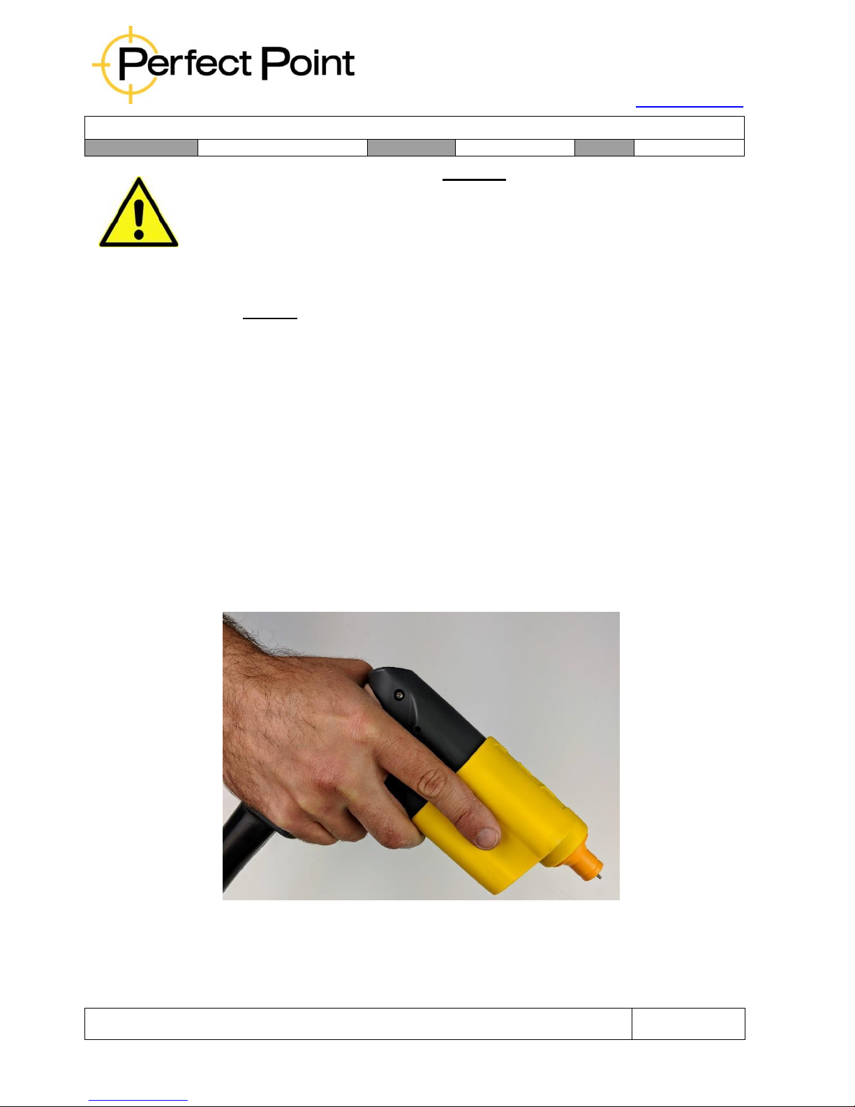
A)
If using an EG hand tool, ensure the EG ground clamp is attached to the
airframe and the hand tool. Grip the E-Drill lightly, nestling the tool between
thumb and forefinger as shown below. Position your second finger to depress
the trigger when ready.
Correct Grip of E-Drill
B)
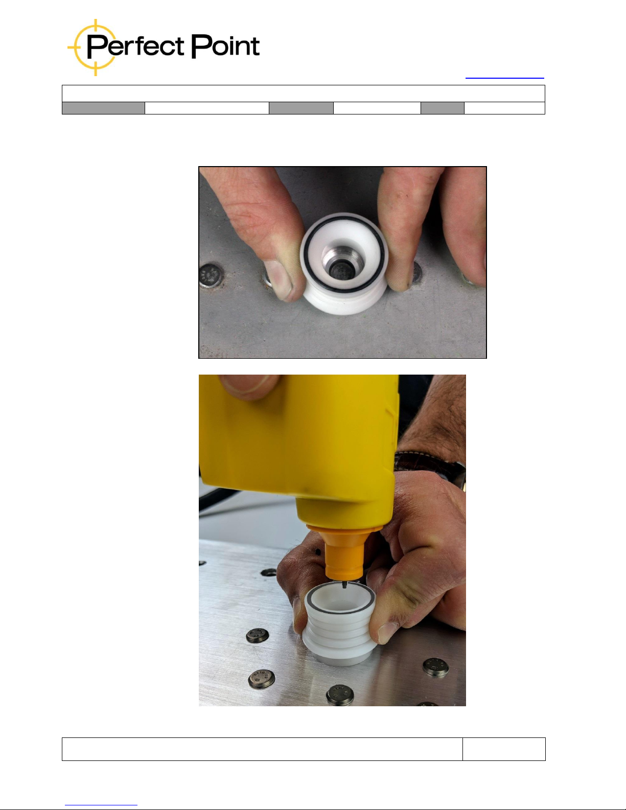
Place the selected Button-head Locator over the fastener and press down to
ensure it is secure, flat to the surface and forms a good water seal. The
Page 31
15192 Triton Lane
Huntington Beach, CA 92649
Office Tel: 714-892-3400
Hotline Tel: 714-891-6533
www.ppedm.com
User Guide
Document No.
61-101
Revision:
107
Date:
10/18/2018
This document is the property of PPedm Corp. and contains proprietary and/or patented information and may not be reproduced in
part or in whole without the express written permission of the company. Perfect Point logo, Perfect Point
TM
and E-Drill
®
are
trademarks of PPedm, Corp. US and worldwide patents pending.
Page 31 of 76
Locator should fit snugly concentric around the fastener head with minimal
play. If there is excessive play then select a locator with a smaller metal insert
or replace the insert.
Correct Grip of Button Locator
Guide Adapter into Locator
Page 32
15192 Triton Lane
Huntington Beach, CA 92649
Office Tel: 714-892-3400
Hotline Tel: 714-891-6533
www.ppedm.com
User Guide
Document No.
61-101
Revision:
107
Date:
10/18/2018
This document is the property of PPedm Corp. and contains proprietary and/or patented information and may not be reproduced in
part or in whole without the express written permission of the company. Perfect Point logo, Perfect Point
TM
and E-Drill
®
are
trademarks of PPedm, Corp. US and worldwide patents pending.
Page 32 of 76
C)
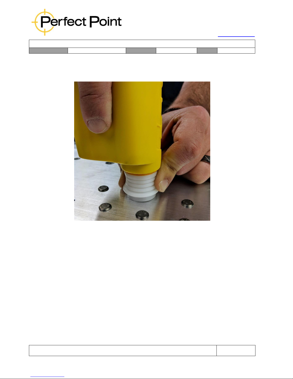
Guide the Adapter installed on the E-Drill into the Button Head Locator and
press firmly but lightly down onto the fastener, (compressing the central EDrill Ground Pin if using a CG hand tool) and sealing the Adapter around the
head of the fastener. Ensure the E-Drill is held perpendicular to the surface.
Concentric E-Drill Alignment
D)
At this point the Adapter should be located concentrically around and over
the fastener, sealing to the surrounding airframe. If in doubt about E-Drill
placement and concentricity go back to step A and try again.
E)
While holding the E-Drill firmly but lightly against the fastener, wrap fingers
around the E-Drill grip and squeeze the trigger with your second finger. The
device will then automatically go through the following sequence:
i.
The Vacuum Pump will turn on to purge the area.
ii.
The cutting electrode will advance until it detects the electrically conductive
head of the fastener, whereupon it will automatically calibrate itself.
iii.
The cutting electrode will retract slightly, the system Water Pump will start
and cutting will be initiated.
Page 33
15192 Triton Lane
Huntington Beach, CA 92649
Office Tel: 714-892-3400
Hotline Tel: 714-891-6533
www.ppedm.com
User Guide
Document No.
61-101
Revision:
107
Date:
10/18/2018
This document is the property of PPedm Corp. and contains proprietary and/or patented information and may not be reproduced in
part or in whole without the express written permission of the company. Perfect Point logo, Perfect Point
TM
and E-Drill
®
are
trademarks of PPedm, Corp. US and worldwide patents pending.
Page 33 of 76
iv.
Cutting will proceed until the prescribed depth is achieved (as defined by the
fastener selection on the Touch-Screen Display)
v.
The power will be shut off, the system Water Pump will stop, and the light
on the back of the hand-tool will illuminate green.
vi.
The system Vacuum Pump will continue to operate until 2 seconds after the
trigger is released.
CAUTION
Failure to establish electrical ground with the E-Drill Ground Pin on the fastener
head (or Ground Wire on the EG E-Drill) will result in a failed cut cycle. If cutting
does not occur, re-clean the fastener head and attempt to re-establish a proper
system ground between the E-Drill Grounding Pin (or the EG Grounding Clamp)
and the Fastener Head. Avoid, striking, grinding, or scraping the E-Drill CG
Ground Pin on the fastener head. Abuse will result in damage and misalignment
of the E-Drill Ground Pin and system failure.
F)
Remove the E-Drill from the fastener, revealing the circular groove cut in the
fastener head.
G)
If the light on the back of the E-Drill does not show green at the completion of
the cut, then the cut may not have completed successfully to depth. If the light
is showing a solid red then the likely cause is either a) bad electrical continuity
resulting from paint or other coating, or b) the fastener material is not the
same as was selected from the library. Ensure all paint or other coatings are
removed, place the E-Drill over the fastener and try again.
A flashing green light indicates the cutting electrode must be replaced. A
flashing red light indicates a system error – see the Touch-Screen Display for
details.
H)
Upon completion of the cut, select a proper size hand punch and center the
punch in the fastener head. Sever the fastener head with a sharp blow on the
punch with a hammer. It may be necessary to strike the punch more than
once. If the fastener head does not separate, the fastener is most likely an
oversize stem. Select an oversize cutting electrode and setting. Re-cut the
fastener and attempt to sever the fastener head again with a punch and
hammer.
Page 34
15192 Triton Lane
Huntington Beach, CA 92649
Office Tel: 714-892-3400
Hotline Tel: 714-891-6533
www.ppedm.com
User Guide
Document No.
61-101
Revision:
107
Date:
10/18/2018
This document is the property of PPedm Corp. and contains proprietary and/or patented information and may not be reproduced in
part or in whole without the express written permission of the company. Perfect Point logo, Perfect Point
TM
and E-Drill
®
are
trademarks of PPedm, Corp. US and worldwide patents pending.
Page 34 of 76
2.5
Removal of Flush-Head Fasteners:
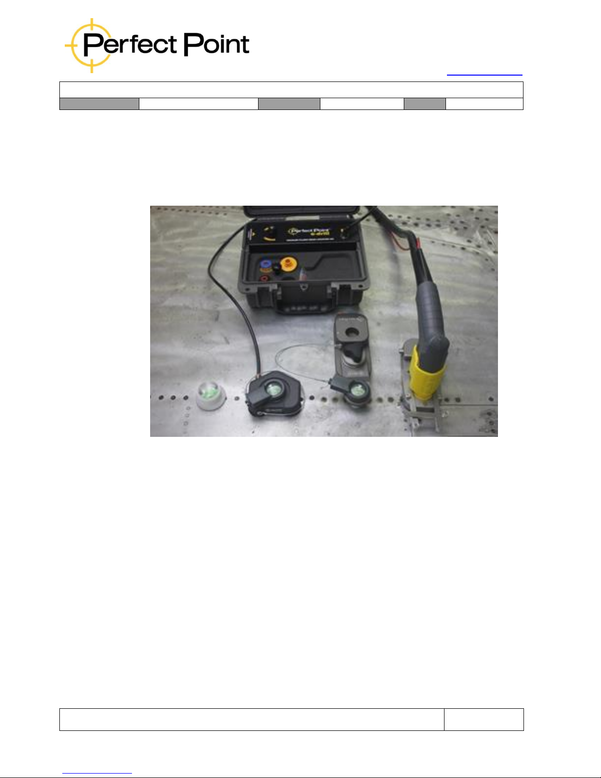
E-drill recommends a precision Vacuum Flush Head Locator (VFHL) tool, for
precision removal of flush fasteners in structure to be re-used. The VFHL is also
especially developed for composite structure, where its use protects not only the
fastener hole, but also the surrounding gel-coat skin.
The standard kit (p/n EDF1321) comprises an air-driven vacuum pump, vacuum
locator and LED bomb sight. There is also a range of special vacuum locators
available for tight areas, wing edges and curved locations.
Usage of the Vacuum Locator family is covered by a separate document. Please
contact PPedm Customer Service Hotline (714.891.6533) or info@ppedm for further
details.
Page 35
15192 Triton Lane
Huntington Beach, CA 92649
Office Tel: 714-892-3400
Hotline Tel: 714-891-6533
www.ppedm.com
User Guide
Document No.
61-101
Revision:
107
Date:
10/18/2018
This document is the property of PPedm Corp. and contains proprietary and/or patented information and may not be reproduced in
part or in whole without the express written permission of the company. Perfect Point logo, Perfect Point
TM
and E-Drill
®
are
trademarks of PPedm, Corp. US and worldwide patents pending.
Page 35 of 76
2.5.1 Universal Flush Head Locator (FHL):
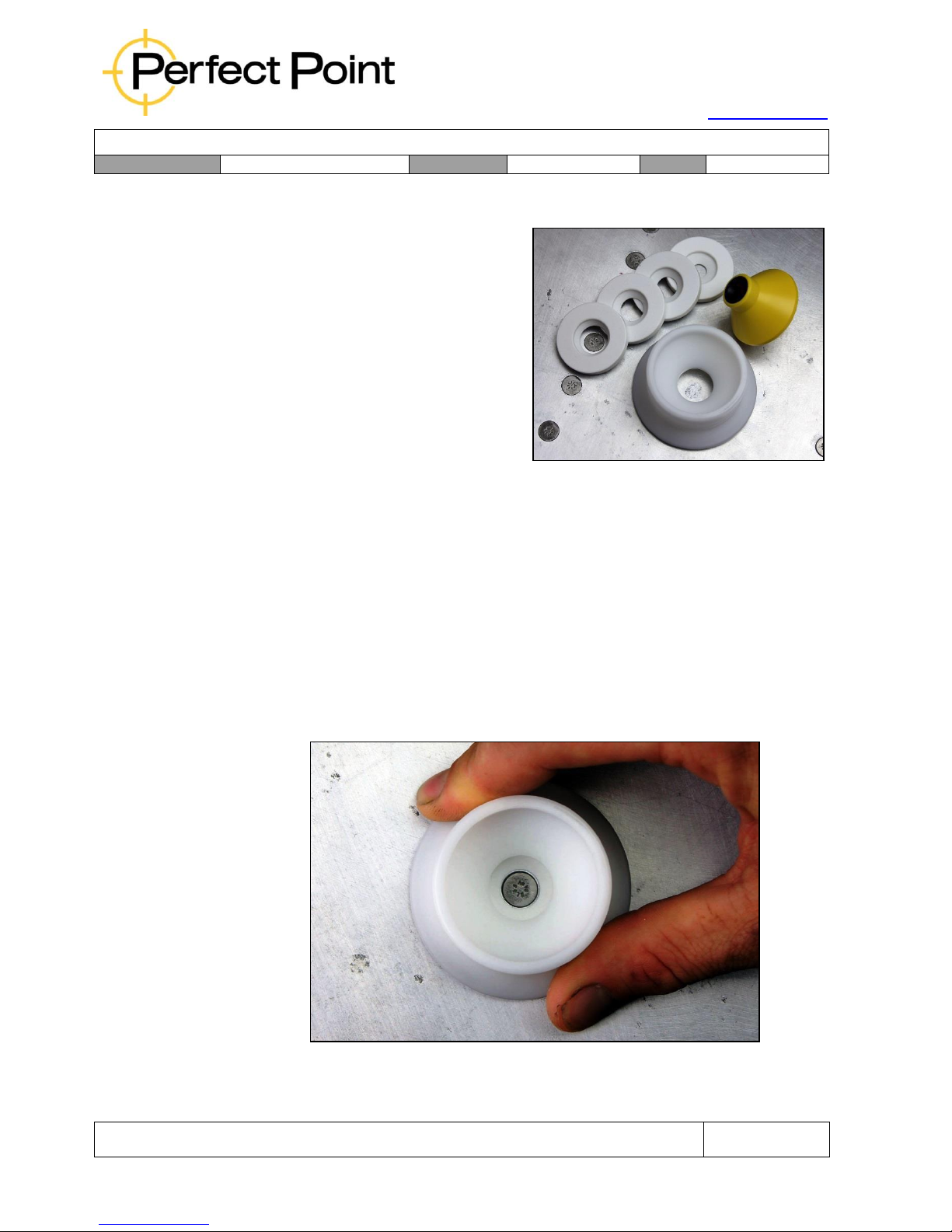
The Universal Flush Head Locator (p/n
EDF0120) is intended for skin removal
where the skin is to be replaced, or
where high precision is not necessary
(such as where larger fasteners are
going to be installed as replacements).
For flush head fasteners the procedure
is the same as for button-head fasteners
except that a different E-Drill Adapter is
used in conjunction with a Flush Head
Locator (FHL). The photograph below
depicts the FHL and proper alignment.
To configure the E-Drill for removal of flush fasteners; select the correct fastener type
on the Touch-Screen Display. Identify from the screen which Electrode and Electrode
Guide are required, and install the electrode, adapter and guide on the hand tool (see
Appendix 2 for details). Clean off any paint or other coatings so that the E-Drill will
make good electrical contact, and you can clearly see the outline of the fastener head.
A)
FHL’s are provided with a range of sizes of sighting apertures suitable for
different fastener head sizes. Select a suitable size FHL aperture.
B)
Place the FHL over the fastener head, using the sighting aperture to ensure
the FHL is concentric.
Flush Head Locator Alignment
Page 36
15192 Triton Lane
Huntington Beach, CA 92649
Office Tel: 714-892-3400
Hotline Tel: 714-891-6533
www.ppedm.com
User Guide
Document No.
61-101
Revision:
107
Date:
10/18/2018
This document is the property of PPedm Corp. and contains proprietary and/or patented information and may not be reproduced in
part or in whole without the express written permission of the company. Perfect Point logo, Perfect Point
TM
and E-Drill
®
are
trademarks of PPedm, Corp. US and worldwide patents pending.
Page 36 of 76
C)
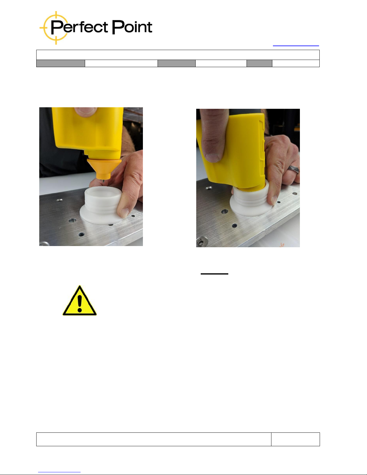
While pressing the FHL firmly onto the airframe so that it does not move,
insert the E-Drill completely into the FHL. Concentricity and
perpendicularityis critical to eliminating airframe damage; if in doubt
remove the E-Drill, check and adjust the FHL and re-insert the E-Drill.
Adaptor into FHL Concentric E-Drill Alignment
CAUTION
When using the CG Hand Tool, failure to establish electrical ground with the EDrill Ground Pin and the fastener head will result in a failed cut cycle. Re-clean the
fastener head and attempt to reestablish a proper system ground between the EDrill Grounding Pin and the fastener head. Avoid, striking, grinding, or scraping
the E-Drill Ground Pin on the fastener head. Abuse will result in damage and
misalignment of the E-Drill Ground Pin and system failure.
D)
Squeeze the trigger until cutting sequence is completed, as with the buttonhead fastener removal.
E)
Upon completion of the cut remove the FHL, select a proper size hand punch
and center the punch in the cut. Sever the fastener head with a sharp blow on
the punch with a hammer. It may be necessary to strike the punch more than
once. If the fastener head does not separate, the fastener is most likely an
oversize stem. Select an oversize cutting electrode and setting. Reapply the
FHL and re-cut the fastener. Attempt to sever the fastener head again with a
punch and hammer.
Page 37
15192 Triton Lane
Huntington Beach, CA 92649
Office Tel: 714-892-3400
Hotline Tel: 714-891-6533
www.ppedm.com
User Guide
Document No.
61-101
Revision:
107
Date:
10/18/2018
This document is the property of PPedm Corp. and contains proprietary and/or patented information and may not be reproduced in
part or in whole without the express written permission of the company. Perfect Point logo, Perfect Point
TM
and E-Drill
®
are
trademarks of PPedm, Corp. US and worldwide patents pending.
Page 37 of 76
CAUTION
When removing Flush Fasteners from COMPOSITE structure, the Vacuum Flush
Head Locator (VFHL) product is strongly recommended. Please visit
WWW.PPEDM.COM or contact your e-drill representative for details.
2.6
Removal of Fastener Collars:
For fastener collars the greatest challenges are cleaning the relevant parts of the
fastener to ensure good electrical contact. Specifically, remove the paint and sealants
from around the collar so that the electrode can make contact. An EG hand-tool is
recommended for collar removal, but if using a CG Hand Tool, for fasteners such as
stump-type Hi-Lok’s which have a hexagonal hole in the shank, remove paint or debris
from inside the hex hole so that the Ground Pin may make contact. When maintaining
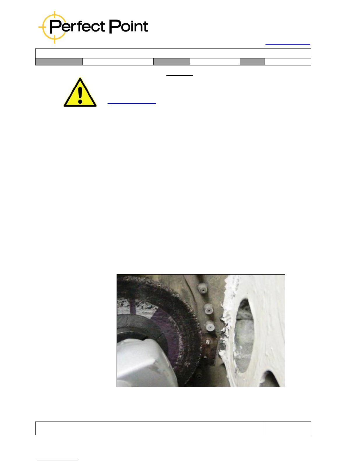
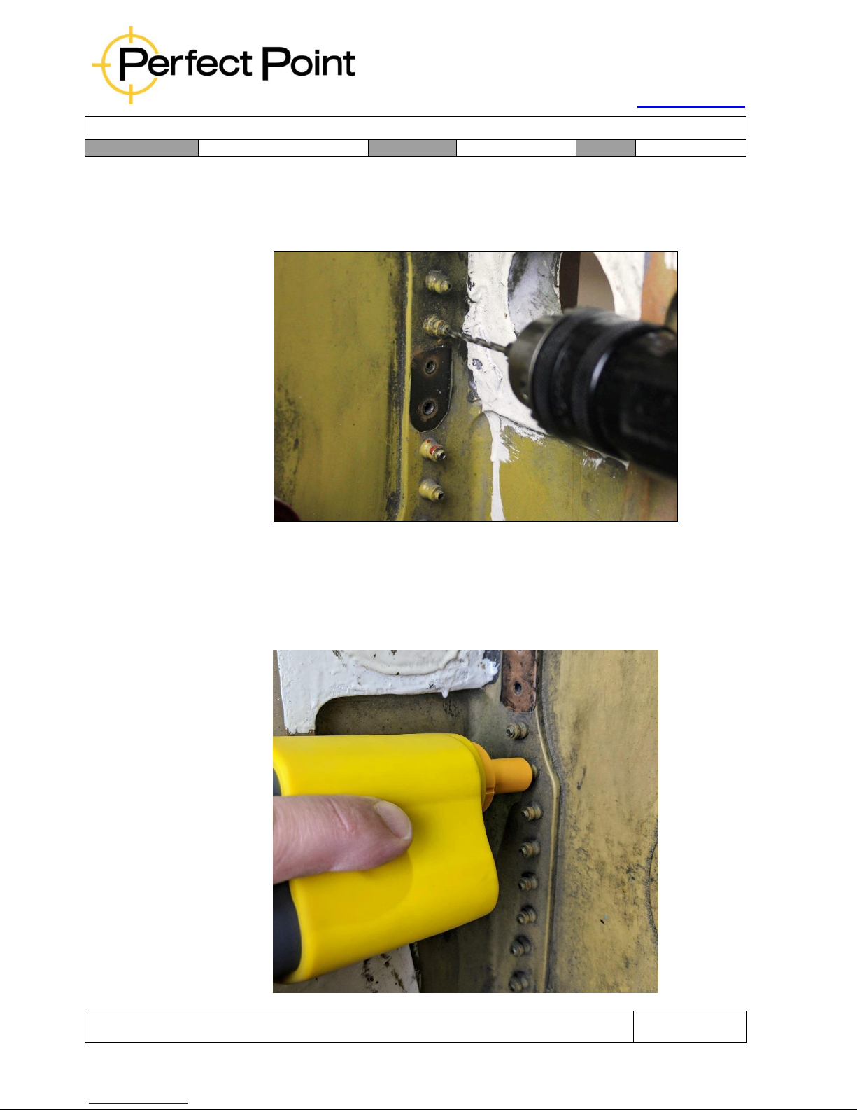
in-service aircraft, it is recommended that these tasks are easiest achieved with an
angle grinder and small drill, as shown below.
A)
Configure the hand-tool with an adapter for removal of the relevant collar
and select the correct collar removal operation from the library on the
Touch-Screen Display interface. Please note that some Huck Lockbolt
collars are typically much longer than other collar types, so there is a
special menu option specifically for long Huck Lockbolts.
B)
Using an angle-grinder, and the relevant personal safety equipment, remove
the entire protrusion of the stem through the collar, thus ensuring a clean
surface.
Page 38
15192 Triton Lane
Huntington Beach, CA 92649
Office Tel: 714-892-3400
Hotline Tel: 714-891-6533
www.ppedm.com
User Guide
Document No.
61-101
Revision:
107
Date:
10/18/2018
This document is the property of PPedm Corp. and contains proprietary and/or patented information and may not be reproduced in
part or in whole without the express written permission of the company. Perfect Point logo, Perfect Point
TM
and E-Drill
®
are
trademarks of PPedm, Corp. US and worldwide patents pending.
Page 38 of 76
C)
When using a CG system, using a small drill bit, clean out the hex hole if
one exists. There is no need to remove metal – simply remove any loose
debris or coatings inside the hole such that good electrical conductivity will
occur.
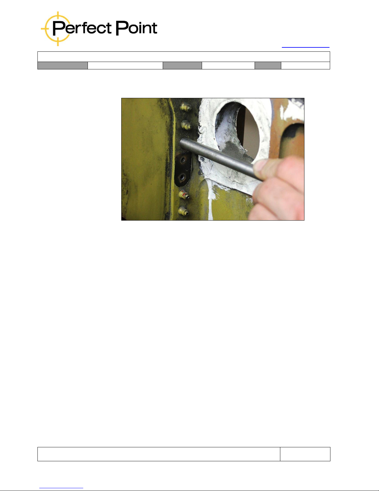
D)
In order to ensure longevity of the O-ring inside the collar adapter it is good
practice to grease the inside of the collar adapter or the outside of the collar.
Push the E-Drill Adapter lightly over the collar, completely enclosing it. Allow
the Adapter to determine the concentricity and alignment of the hand-tool.
Press down to make a seal and squeeze the trigger.
Page 39
15192 Triton Lane
Huntington Beach, CA 92649
Office Tel: 714-892-3400
Hotline Tel: 714-891-6533
www.ppedm.com
User Guide
Document No.
61-101
Revision:
107
Date:
10/18/2018
This document is the property of PPedm Corp. and contains proprietary and/or patented information and may not be reproduced in
part or in whole without the express written permission of the company. Perfect Point logo, Perfect Point
TM
and E-Drill
®
are
trademarks of PPedm, Corp. US and worldwide patents pending.
Page 39 of 76
E)
After cutting the collar drive the shank through to release the collar and
remove the pin.
2.7
Removal of Blind Core-Bolt Fasteners (Cherry, OSI etc.):
Some fasteners have a separate core bolt, removal of which will facilitate
disassembly, or a much simpler drilling operation. Monogram OSI fasteners are an
example of the former, while Cherry and Huck Unimatic blind fasteners are an
example of the latter. Other types of fasteners may also benefit from similar
techniques. Both OSI and Blind fasteners have specific entries in the Touch-Screen
Display fastener library, but both have specific techniques, listed below:
2.7.1
Monogram OSI Fasteners:
OSI-bolts, as they are known, rarely need to be removed. An OSI can easily
be removed by removing the head off the core-bolt, then driving out the core
and the tail, and then pulling out the body. Typically, an electrode one size
down from the fastener step size is used. For example a 1/4” OSI fastener
core-bolt would be removed using a 3/16” electrode.
2.7.2
Monogram Composi-Lok Fasteners:
Composi-Lok fasteners are typically difficult to remove with their two-piece
construction. These can be removed using either a EG E-Drill or a CG E-Drill
and the plus series of electrodes. These were specifically designed to both
accommodate the slightly larger shank diameter of these fasteners and to
significantly reduce the removal strike force required with the punch buddy. A
standard size Punch Buddy is used when removing the fasteners. Note, when
removing flush head Composi-Lok fasteners it is recommended to use a VHL
Page 40
15192 Triton Lane
Huntington Beach, CA 92649
Office Tel: 714-892-3400
Hotline Tel: 714-891-6533
www.ppedm.com
User Guide
Document No.
61-101
Revision:
107
Date:
10/18/2018
This document is the property of PPedm Corp. and contains proprietary and/or patented information and may not be reproduced in
part or in whole without the express written permission of the company. Perfect Point logo, Perfect Point
TM
and E-Drill
®
are
trademarks of PPedm, Corp. US and worldwide patents pending.
Page 40 of 76
and when locating using the bomb sight to locate on the center stud not the
head O.D. due to the fasteners poor head to shank concentricity.
2.7.3
Blind Fasteners:
Blind Cherry Fasteners, flush and protruding head, are removed in a simple
one step process with the E-Drill. The process of weakening the lock collar
wall and creating a fracture point within the head is accomplished with one
cut. The Cherry setting in the Hand Held Terminal, and accurate location of
the hand-tool to the fastener head will accommodate ease of Cherry Rivet
removal. Cherry fasteners have a different set of parameters than other more
standardized fasteners due to the nature of their construction. Known as an
extremely high strength fastener they have a complex structure, therefore the
set up will be different. Pay particular attention to the electrode
recommendation on the terminal, since typically nominal Cherry fasteners
require an oversize electrode.
Once the cut is completed, a parallel punch which equals the fastener nominal
stem size should be used. One simple punch with a hammer will shear the
fastener head and knock stem and sleeve out together. DO NOT use an antiskid punch or punch-buddy for blind fastener removal.
2.8 Electrode Replacement:
Electrode replacement is necessary when either:
A)
The current electrode is consumed as indicated by a flashing green light on
the hand-tool and a message on the Touch-Screen Display, or…
B)
When changing to a different fastener with different stem diameter or
oversize type.
CAUTION
Each FASTENER SIZE and diameter, and oversize fastener has a matching electrode
SIZE. When changing to a different stem diameter or oversize type Fastener, the
proper corresponding ELECTRODE MUST BE INSTALLED FOR SUCCESSFUL
SYSTEM OPERATION.
To replace an electrode, the procedure is as follows:
1.
Unlock the E-Drill Adapter by twisting in a counter-clockwise direction (when
viewed from the front of the E-Drill), then pull the adapter straight off.
Page 41
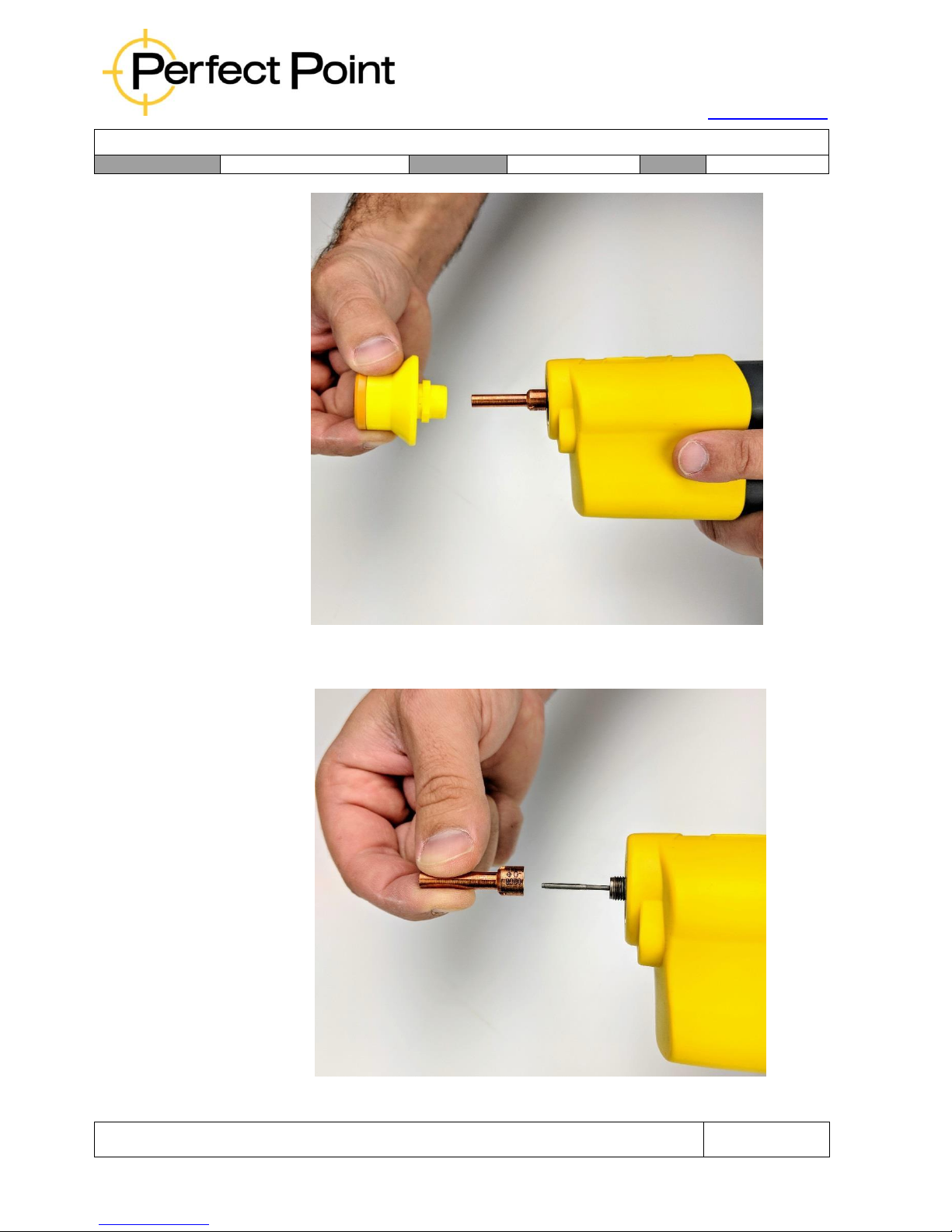
15192 Triton Lane
Huntington Beach, CA 92649
Office Tel: 714-892-3400
Hotline Tel: 714-891-6533
www.ppedm.com
User Guide
Document No.
61-101
Revision:
107
Date:
10/18/2018
This document is the property of PPedm Corp. and contains proprietary and/or patented information and may not be reproduced in
part or in whole without the express written permission of the company. Perfect Point logo, Perfect Point
TM
and E-Drill
®
are
trademarks of PPedm, Corp. US and worldwide patents pending.
Page 41 of 76
2.
Unthread the existing electrode (it is hand-tight and should be removable without
any tools. If necessary, use the provided torque-ring wrench)
Page 42
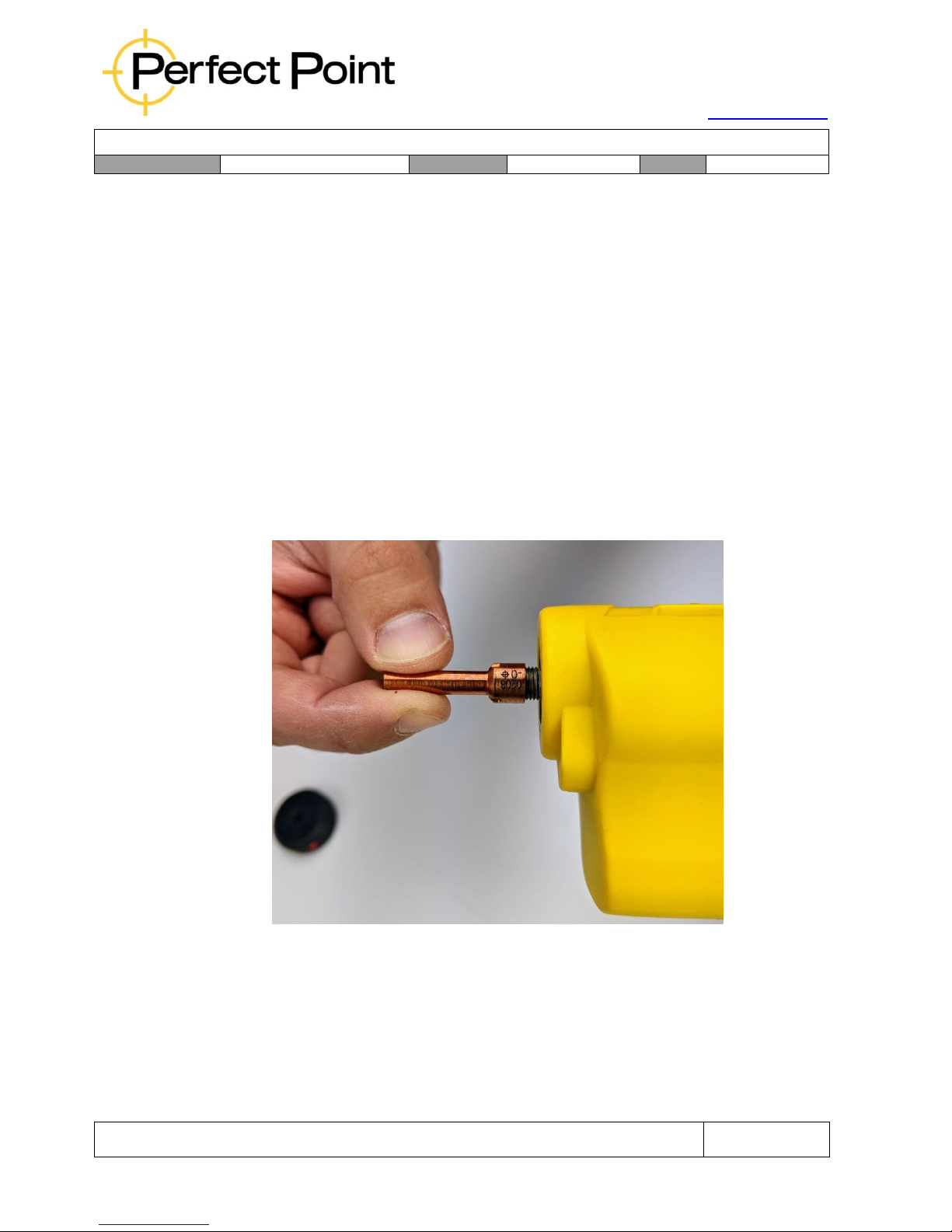
15192 Triton Lane
Huntington Beach, CA 92649
Office Tel: 714-892-3400
Hotline Tel: 714-891-6533
www.ppedm.com
User Guide
Document No.
61-101
Revision:
107
Date:
10/18/2018
This document is the property of PPedm Corp. and contains proprietary and/or patented information and may not be reproduced in
part or in whole without the express written permission of the company. Perfect Point logo, Perfect Point
TM
and E-Drill
®
are
trademarks of PPedm, Corp. US and worldwide patents pending.
Page 42 of 76
Note: The electrode may need to be advanced out of the device to make access
easier. If this is necessary, then simply depress the trigger until the electrode is
fully advanced.
Occasionally, when the electrode is depleted during a collar cutting operation
(flashing green light) the electrode may still not be advanced enough. In this case
the retract button should be pressed momentarily, then the trigger may be
depressed and the electrode will advance completely.
If the cutting electrode is being changed because of a change of fastener type,
then it may be saved and used again later. If the electrode is indicated as needing
replacement, then it should be discarded. Attempts to keep using a worn-out
electrode could damage the mechanism.
3.
Check that the threads are clean on the front of the hand-tool and screw the
replacement electrode hand-tight but firmly on to the front of the E-Drill.
Page 43
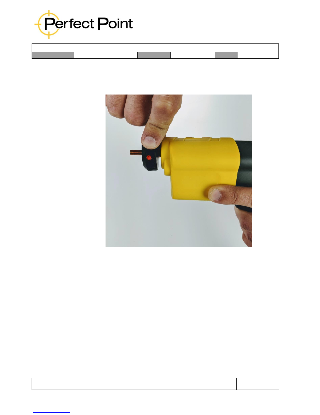
15192 Triton Lane
Huntington Beach, CA 92649
Office Tel: 714-892-3400
Hotline Tel: 714-891-6533
www.ppedm.com
User Guide
Document No.
61-101
Revision:
107
Date:
10/18/2018
This document is the property of PPedm Corp. and contains proprietary and/or patented information and may not be reproduced in
part or in whole without the express written permission of the company. Perfect Point logo, Perfect Point
TM
and E-Drill
®
are
trademarks of PPedm, Corp. US and worldwide patents pending.
Page 43 of 76
4.
Push and engage the Torque-ring Wrench over the electrode and tighten. The
torque-ring will “skip” when the required torque is reached. Remove the Torquering and replace the E-Drill Adapter on the front of the hand-tool.
Page 44
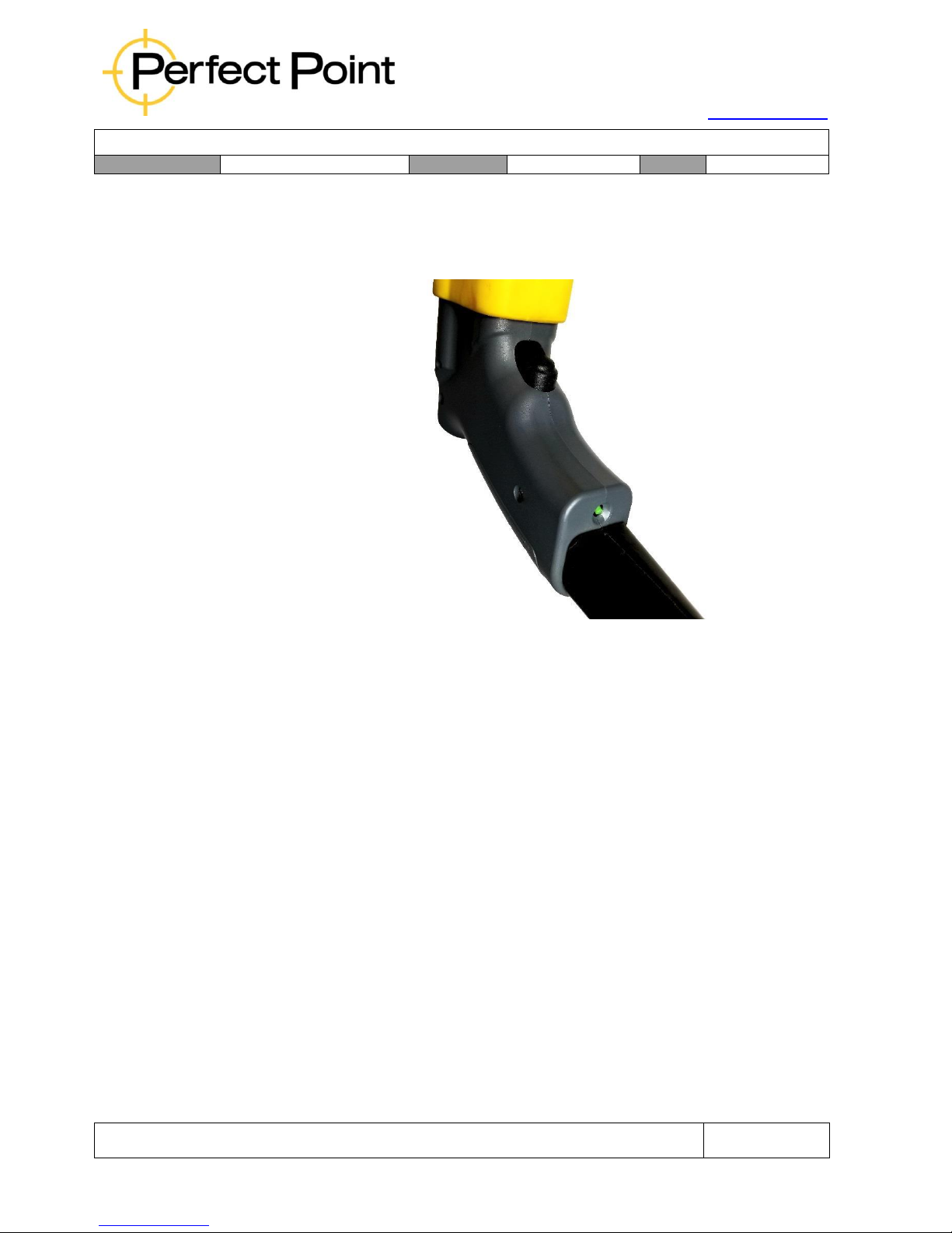
15192 Triton Lane
Huntington Beach, CA 92649
Office Tel: 714-892-3400
Hotline Tel: 714-891-6533
www.ppedm.com
User Guide
Document No.
61-101
Revision:
107
Date:
10/18/2018
This document is the property of PPedm Corp. and contains proprietary and/or patented information and may not be reproduced in
part or in whole without the express written permission of the company. Perfect Point logo, Perfect Point
TM
and E-Drill
®
are
trademarks of PPedm, Corp. US and worldwide patents pending.
Page 44 of 76
5.
Retract the cutting electrode by pressing and holding down the green retract
button in the base of the grip until the green light illuminates indicating the
electrode is fully retracted.
Note: If the replacement electrode is already part-worn then it only needs to be
retracted just inside the E-Drill Adapter. Then during the first cut it will reach its
correct cutting position faster.
Note: Electrode Torque-Ring Wrench torque is factory set and identified as
calibrated with locking compound. Do not attempt adjustment of the Torque-Ring
Wrench setting screws.
2.9 Installing the Umbilical Extension:
The standard hand-tool is provided with a 10’ umbilical connecting it to the Mobile
Service Unit (MSU). This configuration is intended for use when the MSU can be
located in close proximity to the workplace, such as in a shop environment, and
eliminates excess cable. For situations where the MSU cannot be located close to the
workplace, such as removal of fasteners on top of wing sections or fuselage, or inside
air-intakes, long cabled hand tools are available with 30’ umbilicals. A 20’ umbilical
extension is also available, increasing the total length from MSU to the standard handtoolhand-tool to 30’
Page 45
15192 Triton Lane
Huntington Beach, CA 92649
Office Tel: 714-892-3400
Hotline Tel: 714-891-6533
www.ppedm.com
User Guide
Document No.
61-101
Revision:
107
Date:
10/18/2018
This document is the property of PPedm Corp. and contains proprietary and/or patented information and may not be reproduced in
part or in whole without the express written permission of the company. Perfect Point logo, Perfect Point
TM
and E-Drill
®
are
trademarks of PPedm, Corp. US and worldwide patents pending.
Page 45 of 76
CAUTION
The system is optimized for no greater than 30’ maximum distance between Cabinet and
Hand-tool. Use of an umbilical Extension with the long-cabled hand-tools (CP1-CED-310
& 320) or usage of multiple extension umbilical’s with short cable hand-tools will
significantly negatively impact cutting performance and will invalidate warranty and
regulatory safety compliance.
To install the Umbilical Extension the procedure is as follows:
1.
Disconnect the hand-tool from the back of the Power Supply Cabinet by
rotating the twist-lock bezel in a counter-clockwise direction, then depressing
the barrel around the push-to-connect fluid fittings and pulling out the fluid
hoses.
2.
Transfer the fluid hoses from the hand-tool umbilical to the female end of
the extension umbilical by depressing the barrel around the push-to-connect
fittings.
3.
Connect the umbilical extension to the rear of the Power Supply Cabinet by
inserting the power connector and rotating the bezel clockwise firmly until a
click is felt. The power connector can only be inserted one way – if it will not
insert then rotate it until insertion is possible. Re-insert the fluid hoses
between the Power Supply Cabinet and the extension umbilical.
4.
Connect the hand-tool to the male end of the umbilical extension by lining
up the electrical connection and the pre-installed fluid pipes and rotating the
bezel to close. The fluid pipes are two different sizes so that they can only
be inserted into the correct couplings as the bezel is turned. Bleed the water
line as described in Section 3.7.
5.
Removal of the Umbilical Cable is the reverse of installation.
2.10 Keys to Successful Operation of the E-Drill:
1.
Select the right fastener setting on the Touch-Screen Display.
2.
Ensure you are using the correct E-Drill Adapter and Electrode for the
fastener you wish to remove.
3.
Lightly locate the hand-tool concentric with the fastener and co-axial with it.
4.
Using thumb and forefinger press the E-Drill lightly down over the fastener in
order to a) depress the central ground pin (CG hand-tool only), and b)
minimize any water leaks which may occur during cutting.
Page 46

15192 Triton Lane
Huntington Beach, CA 92649
Office Tel: 714-892-3400
Hotline Tel: 714-891-6533
www.ppedm.com
User Guide
Document No.
61-101
Revision:
107
Date:
10/18/2018
This document is the property of PPedm Corp. and contains proprietary and/or patented information and may not be reproduced in
part or in whole without the express written permission of the company. Perfect Point logo, Perfect Point
TM
and E-Drill
®
are
trademarks of PPedm, Corp. US and worldwide patents pending.
Page 46 of 76
5.
Allow the E-Drill to reach its own perpendicularity to the fastener as influenced
by the E-Drill Adapter and its seal, and then wrap the fingers around the grip
to hold securely during cutting.
6.
Depress the trigger on the E-Drill and keep the trigger depressed until the
process is completed, as indicated by the status light on the back of the
hand-tool illuminating green.
7.
Hold the hand-tool as steady as possible during the cutting process.
8.
Hold the E-Drill over the fastener for a second with the trigger depressed
allowing the vacuum system to suck up any excess water left behind by the
process. The vacuum will continue to operate for as long as the trigger is
depressed.
Page 47

15192 Triton Lane
Huntington Beach, CA 92649
Office Tel: 714-892-3400
Hotline Tel: 714-891-6533
www.ppedm.com
User Guide
Document No.
61-101
Revision:
107
Date:
10/18/2018
This document is the property of PPedm Corp. and contains proprietary and/or patented information and may not be reproduced in
part or in whole without the express written permission of the company. Perfect Point logo, Perfect Point
TM
and E-Drill
®
are
trademarks of PPedm, Corp. US and worldwide patents pending.
Page 47 of 76
3.0
SYSTEM MAINTENANCE:
Periodic simple maintenance is required to keep the system operating properly. System
maintenance is controlled by internal cut cycle counters, that will advise the operator when
maintenance is recommended. Once the predetermined cut cycles are reached operator
intervention is required to perform maintenance and reset the counters.
3.1
Maintenance Warnings:
A)
The Sediment Tank Maintenance Counter will provide a maintenance
warning at 1000 cut cycles. The system will continue to operate, but
maintenance is recommended before the next shift. The Touch-Screen
Display will indicate a “Sediment Tank Full” message when this occurs.
B)
After the warning screen is activated, the system will count-down an
additional 500 cut cycles before the system will automatically shut down. It is
recommended that sediment tank maintenance be completed between shifts,
prior to the system forcing a shutdown.
C)
The Filter Maintenance Counter will provide a maintenance warning to
replace the pleated filter (see below) at 5000 cut cycles. As with the Sediment
Tank, the system will continue to operate, but maintenance is recommended
before the next shift. The Touch-Screen Display will indicate a “Filter
Replacement Required” message when this occurs.
D)
After the warning screen is activated, the system will count-down an
additional 500 cut cycles before the system automatically shuts down at the
mandatory 5500 cut cycle limit. As before, it is recommended that a filter
replacement is completed between shifts, prior to the system forcing a
shutdown.
3.2
Reset Maintenance Counters:
If performed correctly, the Sediment Tank and Filter procedures (refer to sections 3.5
& 3.6 below), will automatically reset their respective counters. However, if the
procedures are performed incorrectly, the counters will not be reset and the system
will still be disabled. Both the Sediment Tank and Filter counters can be reset in
Advanced Mode (see Appendix 1, Section 1.4 for reset instructions). It is not
recommended that a counter be defeated by resetting it without servicing the system,
and such activity will void the system warranty.
Page 48
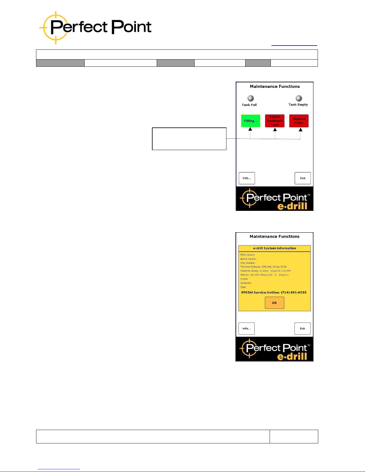
15192 Triton Lane
Huntington Beach, CA 92649
Office Tel: 714-892-3400
Hotline Tel: 714-891-6533
www.ppedm.com
User Guide
Document No.
61-101
Revision:
107
Date:
10/18/2018
This document is the property of PPedm Corp. and contains proprietary and/or patented information and may not be reproduced in
part or in whole without the express written permission of the company. Perfect Point logo, Perfect Point
TM
and E-Drill
®
are
trademarks of PPedm, Corp. US and worldwide patents pending.
Page 48 of 76
3.3
Maintenance Screens:
System maintenance functions are accessed through
the System Maintenance Screen, by pressing the
Maintenance button at the bottom right of the Home
screen.
Buttons turn GREEN
when function is active
Touching a button on the maintenance screen will
turn the button on (green) activating the function.
Touching the button again will turn the function off
(red). The Tank Full and Tank Empty round
indicator “lights” display system water level status in
the Sediment Tank and will turn on and off
automatically indicating water levels as the system is
serviced.
The Informational screen is accessed by touching the
“Info” button in the lower left corner of the main
maintenance screen. The information screen
contains system configuration details and firmware
revisions. The screen also contains the Total
Cycles, Sediment Tank, and Filter counters.
3.4
System “Top Off”:
The DI water system requires periodic filling or “Top-Off” to replace small amounts of
DI water lost during the cutting cycle. Should the system run low on water during
operation, the hand tool will indicate a flashing red light and the display will indicate a
“Low Water Level” condition. To “Top-off”, fill an open container with approximately 1
gallon of clean water, enter the maintenance Screen, touch the Top-Off function, and
immerse the Adapter of the E-Drill in a vessel of water (do not submerge the entire
drill, only the front of the E-Drill Adapter should be submerged).
Page 49
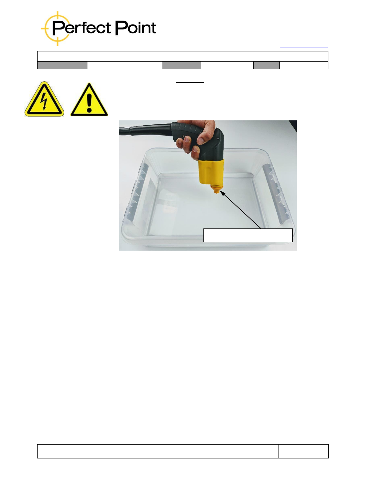
15192 Triton Lane
Huntington Beach, CA 92649
Office Tel: 714-892-3400
Hotline Tel: 714-891-6533
www.ppedm.com
User Guide
Document No.
61-101
Revision:
107
Date:
10/18/2018
This document is the property of PPedm Corp. and contains proprietary and/or patented information and may not be reproduced in
part or in whole without the express written permission of the company. Perfect Point logo, Perfect Point
TM
and E-Drill
®
are
trademarks of PPedm, Corp. US and worldwide patents pending.
Page 49 of 76
CAUTION
Submersing the E-Drill, its mechanism, or any parts other than the Adapter will
destroy the E-Drill electronics and void the system warranty. Submerging the EDrill in water may also cause operator injury due to electrical shock.
When the Tank is full the Full LED indicator will illuminate green and the pump will
turn off automatically. The system is then ready for continued use.
Note: The Top-Off pump may be stopped manually by pressing the Top-Off button
a second time. Exiting the Maintenance Screen will also automatically turn
the Top-Off function off. However, a “Low Water level” condition can only be
cleared by completely filling the system, stopping the fill process manually or
exiting Maintenance Screen will not clear the error.
The Top-Off function will not work if the tank is already full.
3.5
Empty Sediment Tank:
The E-Drill is provided with a maintenance kit including a drain bowl, a Drain/Bleed
Tube Pair and a Filter Bowl Wrench for the two water tanks. These tools are used
when servicing the Sediment tank or Filter tank. Sediment tank cleaning is carried out
as follows:
A)
Disconnect the two Hand-Tool water connections on the back of the Power
Supply Cabinet and connect one end of the Service Drain/Bleed Tube Pair
to the Mobile Service Unit PRESSURE and VACUUM ports. Place the other
end of the Drain/Bleed Tube Pair in a 1-gallon container (minimum).
Only Submerge Adapter Tip
Page 50
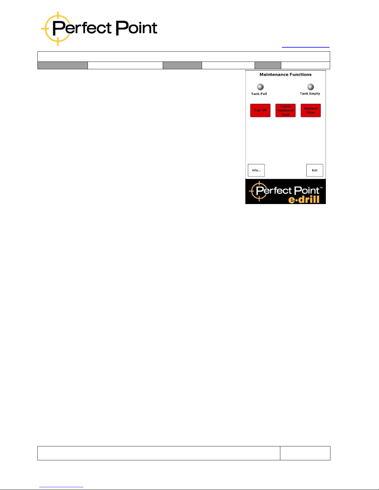
15192 Triton Lane
Huntington Beach, CA 92649
Office Tel: 714-892-3400
Hotline Tel: 714-891-6533
www.ppedm.com
User Guide
Document No.
61-101
Revision:
107
Date:
10/18/2018
This document is the property of PPedm Corp. and contains proprietary and/or patented information and may not be reproduced in
part or in whole without the express written permission of the company. Perfect Point logo, Perfect Point
TM
and E-Drill
®
are
trademarks of PPedm, Corp. US and worldwide patents pending.
Page 50 of 76
B)
Empty the system by pressing the Empty
Sediment Tank button in the Maintenance
Screen of the Touch-Screen Display. The
button will change color to green and the
system will automatically pump out sufficient
water for the Sediment Bowl to be removed
and cleaned. The pump will terminate
automatically when sufficient water has
been removed.
Once the pump is started a “pop-up” screen
will appear prompting the user to reset the
sediment tank counter. This function allows
the operator to determine if the sediment
tank is truly to be emptied, or if other system
bleed/charge procedures are being
performed (see Section 3.7) and allows the
cut cycle counter to be reset or ignored as appropriate. Press the YES
button to proceed.
C)
Loosen the Dielectric Lock-Bolt on the frame to the right of the entire Filter
Assembly. Rotate the assembly until nearly horizontal (see photograph at the
end of this section) and retighten the Lock-Bolt.
D)
Using the Filter Bowl Wrench provided with the system, loosen the Sediment
Bowl (bowl on the right, marked Sediment). Use caution; there will be some
residual water in the bowl. Unthread by hand; carefully remove the bowl
without touching the pick-up tube or fragile level sensor assembly to its right.
Dump sediment and clean out the Sediment Bowl with a clean, lint free shop
towel. Do not attempt to clean the Level Sensor Sleeve.
E)
Prior to reassembly, inspect the bowl to ensure the large O-ring seal is clean
and undamaged, properly lubricated and seated before reinstalling. Handthread the tank onto the Filter Cap Assembly, taking care not to unseat the
O-ring or touch the center pick-up tube or the level sensor assembly. Use the
Filter Bowl Wrench provided with the system to lightly tighten the bowl.
Return the Bowl Assembly to vertical position and tighten the Dielectric Filter
Assembly Lock Bolt.
F)
Ensure that the end of the drain/bleed tube is submerged in water, then
recharge system using Dielectric Top-Off button. Ensure that water is being
drawn into the system by watching for movement of air-bubbles when the
procedure is started. If water is not being drawn into the system, it is
likely that the O-ring is incorrectly installed. Re-tilt the assembly and
Page 51
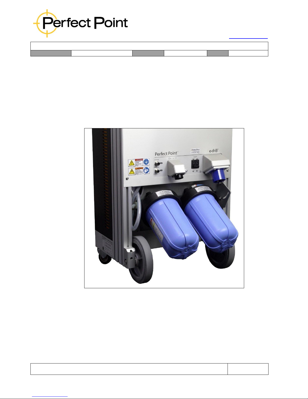
15192 Triton Lane
Huntington Beach, CA 92649
Office Tel: 714-892-3400
Hotline Tel: 714-891-6533
www.ppedm.com
User Guide
Document No.
61-101
Revision:
107
Date:
10/18/2018
This document is the property of PPedm Corp. and contains proprietary and/or patented information and may not be reproduced in
part or in whole without the express written permission of the company. Perfect Point logo, Perfect Point
TM
and E-Drill
®
are
trademarks of PPedm, Corp. US and worldwide patents pending.
Page 51 of 76
re-install the bowl after O-ring seal is rectified.
G)
When the tank is full the pump will automatically turn off. You may need to
add more water to fully fill the tank.
Note: The pump may be stopped manually by pressing the Empty Sediment Tank
button a second time.
Note: The Empty Sediment Tank function only drains the Sediment Tank for
servicing. It does not empty the entire system.
Rear of MSU with Filter Assembly in rotated position
3.6
Replace Filter:
Completely emptying the system for replacement of the system filter is accomplished
in the Replace Filter function. Procedure is as follows:
Page 52
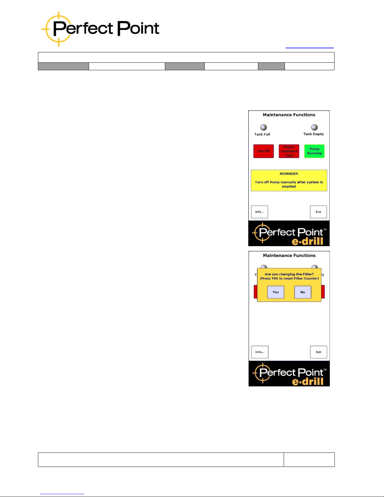
15192 Triton Lane
Huntington Beach, CA 92649
Office Tel: 714-892-3400
Hotline Tel: 714-891-6533
www.ppedm.com
User Guide
Document No.
61-101
Revision:
107
Date:
10/18/2018
This document is the property of PPedm Corp. and contains proprietary and/or patented information and may not be reproduced in
part or in whole without the express written permission of the company. Perfect Point logo, Perfect Point
TM
and E-Drill
®
are
trademarks of PPedm, Corp. US and worldwide patents pending.
Page 52 of 76
A)
Connect the Fill/Drain Tubing to the Mobile Service Unit PRESSURE and
VACUUM ports. Place the other end of the Drain/Bleed Tube Pair in a 2-gallon
container (minimum).
B)
Press the Replace Filter button to empty the
system.
The PUMP RUNNING message will display
notifying the user that the function will run the fluid
pump continuously until it is shut off manually by
the operator. The pop-up screen reminds the
operator that the running pump will need to be
watched and shut off manually when no more
water is being pumped out.
Press the green Pump Running button to stop the
pump.
C)
When the system is empty, and pump is
stopped, a “pop up” screen will appear
prompting the user to reset the Filter Counter.
This function allows the operator to determine if
system maintenance is being performed or if
other system Bleed/Charge operations are being
performed (see Section 3.7), and allow the cut
cycle counter to be reset or ignored as
appropriate.
D)
Loosen the Dielectric Lock-Bolt to the right of the entire Filter Assembly. Rotate
the assembly until nearly horizontal (see photograph on page 44) and retighten
the Lock-Bolt.
E)
Using the Filter Bowl Wrench provided with the system, loosen the Filter Bowl.
Use caution; there will be some residual water in the bowl. Unthread by hand
Page 53

15192 Triton Lane
Huntington Beach, CA 92649
Office Tel: 714-892-3400
Hotline Tel: 714-891-6533
www.ppedm.com
User Guide
Document No.
61-101
Revision:
107
Date:
10/18/2018
This document is the property of PPedm Corp. and contains proprietary and/or patented information and may not be reproduced in
part or in whole without the express written permission of the company. Perfect Point logo, Perfect Point
TM
and E-Drill
®
are
trademarks of PPedm, Corp. US and worldwide patents pending.
Page 53 of 76
and carefully remove the bowl and filter. Discard the old filter, clean out the bowl
with a lint-free cloth, and install a new filter. (Do not attempt to wash out and reuse an old filter. It is a single-use device and will not re-seat correctly.)
F)
Prior to reassembly, inspect the bowl to ensure the large O-ring seal is clean
and properly lubricated and seated before reinstalling. Hand-thread the tank
back onto the Filter Cap Assembly, taking care not to unseat the O-ring. Use the
Filter Bowl Wrench provided with the system to tighten the bowl.
G)
Return the Bowl Assembly to vertical position and tighten the Dielectric Filter
Assembly Lock Bolt.
H)
After filter replacement the system must be completely refilled and bled. Follow
section 3.7 for recharge and bleed procedure. If water is not being drawn into the
system, it is likely that the O-ring is incorrectly installed. Re-tilt the assembly and
re-install the bowl after O-ring seal is rectified.
3.7
System Bleeding and Charging Procedure:
System maintenance and connecting/disconnecting system components can cause
air to become entrapped in the DI water system. Bleeding and charging is sometimes
required to assure there is no trapped air in the DI system.
Note: During the following operations there may be some “screeching” from the
Mobile Service Unit Pressure Regulator as the air is bled out of the system.
This is normal and will disappear as the system is successfully bled.
A)
Enter maintenance mode on the Touch-Screen Display, attach the Fill/Drain
Tubing and run the Top-Off procedure (see Section 3.4) to assure the system is
completely filled.
B)
In the Maintenance Screen on the Touch-Screen Display, run the Empty
Sediment Tank function (see Section 3.5). Water and entrapped air will be
expelled through the tubing, until you achieve a strong stream of water. After
expelling approximately 1 gallon of water the pump will automatically stop. The
system will prompt you to confirm that you are resetting the Sediment Tank
Counter. Respond by pressing the No button.
C)
Re-run the “Top-Off” procedure to refill the system (see Section 3.4).
This procedure should be sufficient to clear excess air out of the system. Repeat this
procedure as necessary to bleed air from the system.
3.8
Checking Vacuum and pressure (CP1-SY-151 only):
Page 54

15192 Triton Lane
Huntington Beach, CA 92649
Office Tel: 714-892-3400
Hotline Tel: 714-891-6533
www.ppedm.com
User Guide
Document No.
61-101
Revision:
107
Date:
10/18/2018
This document is the property of PPedm Corp. and contains proprietary and/or patented information and may not be reproduced in
part or in whole without the express written permission of the company. Perfect Point logo, Perfect Point
TM
and E-Drill
®
are
trademarks of PPedm, Corp. US and worldwide patents pending.
Page 54 of 76
CP1-SY-151 is provided with Vacuum and Pressure gauges to check the performance
of the Dielectric water system. Vacuum and pressure may be checked in Advanced
Mode (see Appendix 1). It is suggested that this check be carried out monthly or when
poor performance is suspected, per the following specifications:
•
Vacuum:
o
Connect the vacuum gauge with the blue hose to the vacuum port on the
back of the MSU.
o
In the advanced menus, under the Manual Tab, press the red Vacuum
button to run the vacuum pump. The indicated vacuum should slowly rise
to -10” inHg in approximately 60 seconds.
o
Press the Vacuum button again to turn the pump off. Vacuum should hold
or degrade slowly over 30 seconds approximately.
•
Pressure:
o
Connect the pressure gauge with the black hose to the pressure port on
the back of the MSU.
o
In the advanced menus, under the Manual Tab, press the red Pressure
button to run the pressure pump. The indicated pressure should quickly r
rise to -80 PSI ±5 PSI.
o
Press the Pressure button again to turn the pump off. Take care when
disconnecting the gauge since the line will still be pressurized.
If either of the above specifications are not met visually inspect the bowl system or
visible tubing for leaks. Also check the bowl O-rings are in-place and not damaged.
Contact PPedm Customer Service Hotline (714.891.6533) if there ae no obvious
leaks and O-ring problems.
3.9
Weekly Maintenance:
Visually inspect the E-Drill for tightness of the cutting electrode, signs of excessive
burning around electrode and Ground Pin (CG system only), or water leakage. The
Ground Pin is of particular importance and the Ground Pin Insulation Sleeve on the
tip of the Ground Pin should be intact (does not apply to EG hand tool).
3.10
Ground Pin Adjustment and Replacement (applies to CG and BG hand-tools
only):
Ground Pin adjustment is a critical parameter in efficient operation of the device (much
like the electrode in a TIG welder). As described in the Weekly Maintenance Schedule
(Section 3.8), the Ground Pin should be regularly checked for excessive burning or
damage and correct protrusion from the front of the E-Drill. The procedure for
checking and adjusting, and if necessary, replacing the ground pin is as follows:
1.
Prior to Ground Pin inspection, advance Electrode to the full forward position;
remove any installed Adapter and the Electrode from the E-Drill and inspect the
Ground Pin for excessive burning and/or damage.
Page 55
15192 Triton Lane
Huntington Beach, CA 92649
Office Tel: 714-892-3400
Hotline Tel: 714-891-6533
www.ppedm.com
User Guide
Document No.
61-101
Revision:
107
Date:
10/18/2018
This document is the property of PPedm Corp. and contains proprietary and/or patented information and may not be reproduced in
part or in whole without the express written permission of the company. Perfect Point logo, Perfect Point
TM
and E-Drill
®
are
trademarks of PPedm, Corp. US and worldwide patents pending.
Page 55 of 76
2.
Place the Ground Pin Setting Tool over the end of the hand-tool and across the
Ground Pin tip. There should be no gap visible between the Gauge and the tip
of the Ground Pin.
3.
If there is a gap the Ground Pin may be adjusted by loosening the internal
Ground Pin Clamp Screw.
CAUTION
DO NOT COMPLETELY REMOVE THE CLAMP SCREW. Completely removing the
screw will allow internal components to drop into the E-Drill housing. Simply loosen
the screw sufficiently to relieve the clamping force on the pin shaft.
4.
Carefully pull the Ground Pin out incrementally (do not use any tools for this – if
properly loosened, the Ground Pin should slide out relatively easily), recheck
Pin length with the Pin Gauge allowing the Gauge to push the Pin back to the
correct protrusion.
5.
To replace the Ground Pin, grip Ground Pin Assembly firmly and pull it straight
out of the nose of the E-Drill taking care not to bend it during extraction. Make
sure there is no remaining clamping force on the Ground Pin if removal is
difficult. As the Ground Pin Assembly is extracted, the Ground Pin Centering
Guide will come out with the Ground Pin. Discard Ground Pin and Centering
Guide once removed.
6.
Lightly coat the shaft of the new Ground Pin Assembly with a light coating of ORing Lube (do not over lubricate). Insert the prepared Ground Pin Assembly into
the nose of the E-Drill pressing it through the E-Drill’s internal seals. Use care
not to bend the Ground Pin during insertion. Use Ground Pin Gauge to set the
proper pin length and secure the Ground Pin Clamp Screw (do not use
excessive torque).
Press the Ground Pin Centering Guide on the Ground Pin Assembly into its seat
in the Electrode Conducting Tube Bore using the tip of an Electrode. Install the
required Electrode and Adapter and resume E-Drill operation.
Page 56

15192 Triton Lane
Huntington Beach, CA 92649
Office Tel: 714-892-3400
Hotline Tel: 714-891-6533
www.ppedm.com
User Guide
Document No.
61-101
Revision:
107
Date:
10/18/2018
This document is the property of PPedm Corp. and contains proprietary and/or patented information and may not be reproduced in
part or in whole without the express written permission of the company. Perfect Point logo, Perfect Point
TM
and E-Drill
®
are
trademarks of PPedm, Corp. US and worldwide patents pending.
Page 56 of 76
3.11
Draining of system for storage or transport.
The Perfect Point E-Drill system should be protected from freezing cold conditions
that can crack or burst de-ionized water connections and plumbing. If the system is
subjected to freezing temperatures, it should be thoroughly inspected by a trained
technician for damage or leaks prior to use. If the system is to be stored or transported
in low temperature conditions, then it should be fully drained first.
To drain the system completely follow section 3.6 (Replace Filter). Before re-use
follow section 3.7 (System Bleeding and Charging) to refill the dielectric system.
Page 57
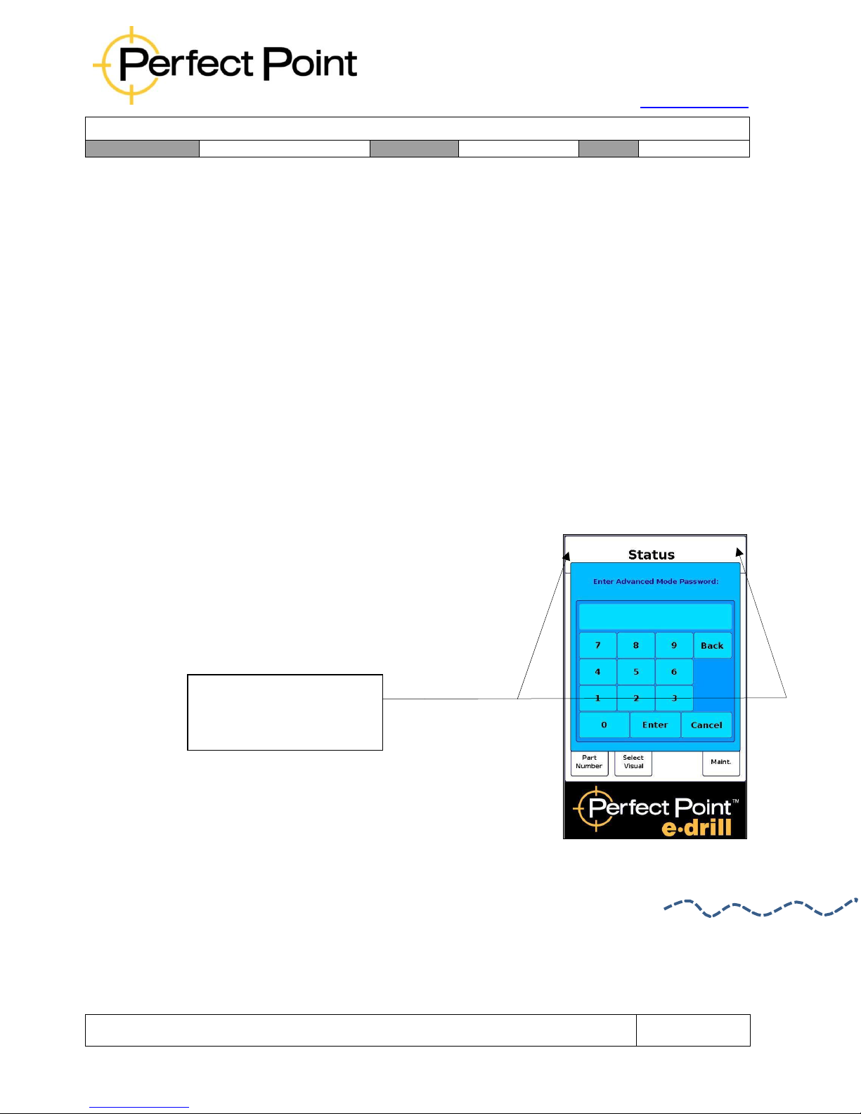
15192 Triton Lane
Huntington Beach, CA 92649
Office Tel: 714-892-3400
Hotline Tel: 714-891-6533
www.ppedm.com
User Guide
Document No.
61-101
Revision:
107
Date:
10/18/2018
This document is the property of PPedm Corp. and contains proprietary and/or patented information and may not be reproduced in
part or in whole without the express written permission of the company. Perfect Point logo, Perfect Point
TM
and E-Drill
®
are
trademarks of PPedm, Corp. US and worldwide patents pending.
Page 57 of 76
4.0
APPENDIX 1. Advanced Functions:
The Advanced Functions screen is provided to enable the system to be adjusted to remove
non-standard fasteners, and to provide functions to assist in fault diagnosis. To access
advanced functions, the user will need to obtain a password from Perfect Point service
personnel.
Advanced functions include:
•
Manual Setting of Depth of Cut and Cycle Time
•
Manual Setting of Retract Distance
•
Manual Extend & Retract of Electrode (May also be activated by function keys).
•
Manual DI Pump and Vacuum Control
•
Manual Spark Power Control
4.1
Password Entry:
To enable the advanced menu tab, return to the home
screen, and then press in sequence the top left corner
of the screen followed by the top right corner, within
2 seconds. A prompt for password will appear.
To enter Advanced Mode
press left top corner of
screen then right.
Page 58
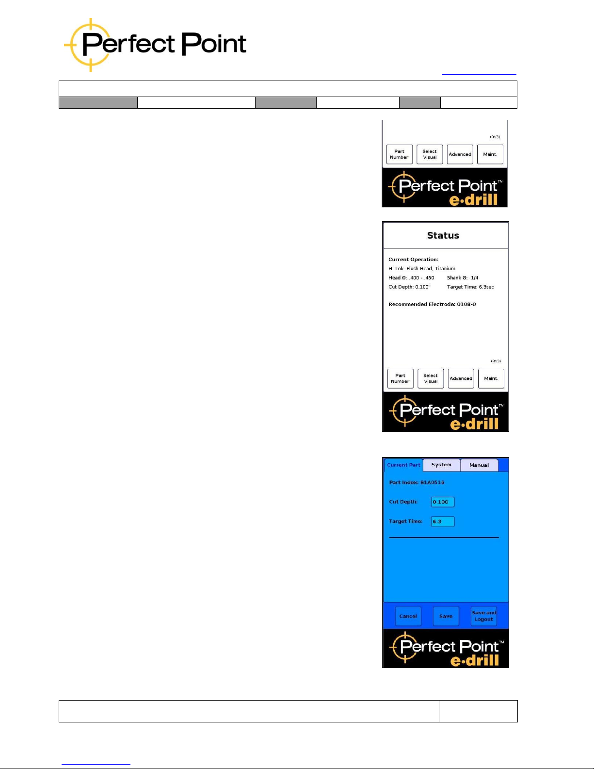
15192 Triton Lane
Huntington Beach, CA 92649
Office Tel: 714-892-3400
Hotline Tel: 714-891-6533
www.ppedm.com
User Guide
Document No.
61-101
Revision:
107
Date:
10/18/2018
This document is the property of PPedm Corp. and contains proprietary and/or patented information and may not be reproduced in
part or in whole without the express written permission of the company. Perfect Point logo, Perfect Point
TM
and E-Drill
®
are
trademarks of PPedm, Corp. US and worldwide patents pending.
Page 58 of 76
Enter the password provided by Perfect Point,
followed by the enter button. If the procedure is
completed correctly, the Advanced Mode will be
enabled. While Advanced Mode is enabled, an
Advanced tab is visible along the bottom of the
screen.
4.2
Accessing Advanced Functions:
Pressing on the advanced tab will access the
advanced functions. The advanced functions screen
is divided into three tabs; Current Part, System and
Reset.
4.3
Current Part tab – Override Library settings:
Under the Current Part tab an advanced user may
override the Cut Depth or the Target Time for the
current fastener being removed. After the setting is
saved, then the home screen will re-appear with the
over-ridden parameters shown in red.
NOTE: The over-ridden values do not modify the
library permanently, and the over-rides are only valid
until another fastener is selected (or the current
fastener re-selected). If you believe a library entry is
incorrect please contact Perfect Point Technical
Support hotline (714-891-6533).
Page 59
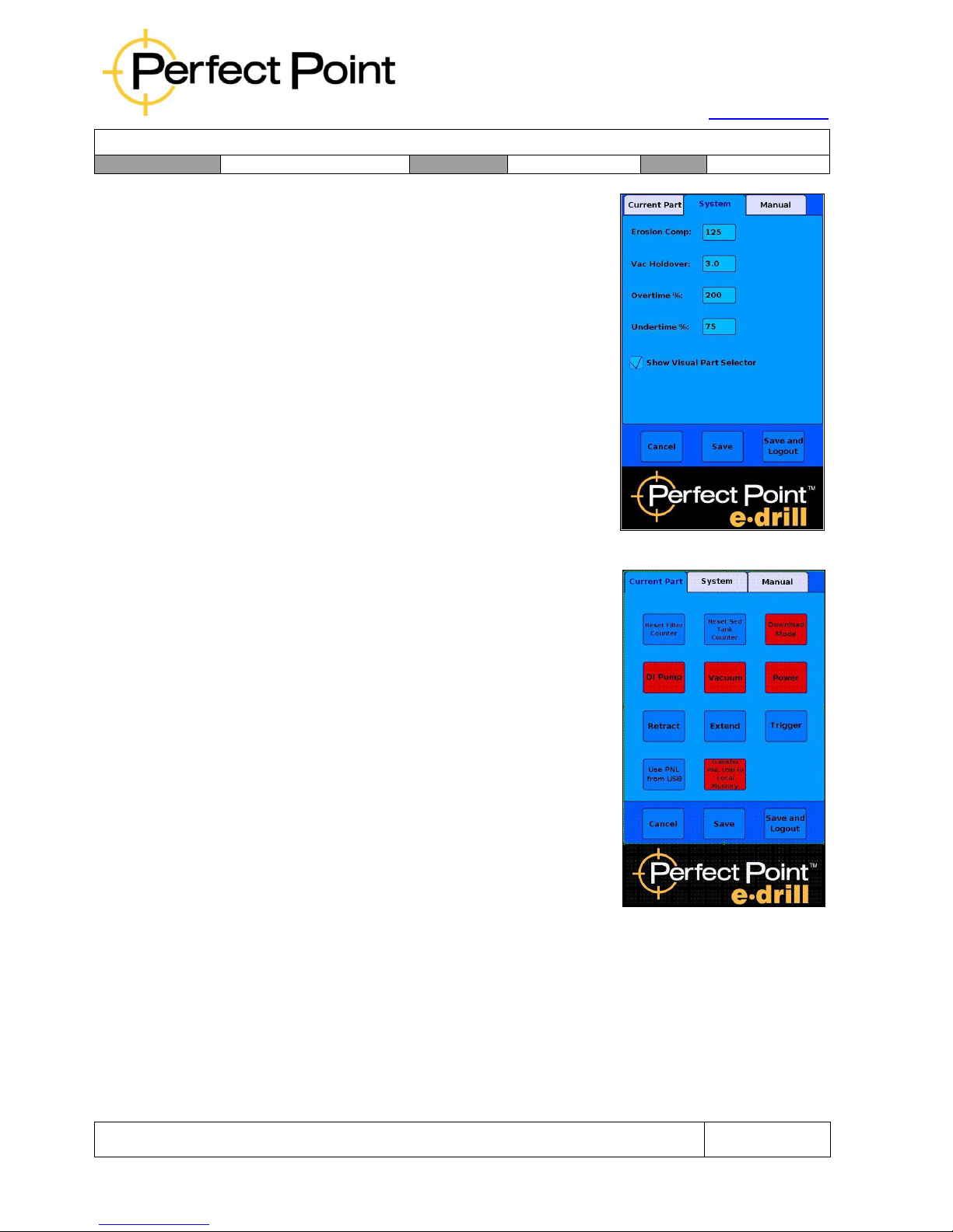
15192 Triton Lane
Huntington Beach, CA 92649
Office Tel: 714-892-3400
Hotline Tel: 714-891-6533
www.ppedm.com
User Guide
Document No.
61-101
Revision:
107
Date:
10/18/2018
This document is the property of PPedm Corp. and contains proprietary and/or patented information and may not be reproduced in
part or in whole without the express written permission of the company. Perfect Point logo, Perfect Point
TM
and E-Drill
®
are
trademarks of PPedm, Corp. US and worldwide patents pending.
Page 59 of 76
4.4
System tab - Override System Cut Parameters:
Under the System tab, an advanced user may
override system cut related parameters, including
Erosion Compensation, Vacuum Hold-Over (after
trigger release), Overtime, and Under-time warning
threshold settings. In addition, there are manual
controls used for error diagnosis and a check-box to
control whether the visual selector is displayed (in
some customer installations the visual selector is not
displayed by default).
NOTE: Changes should only be made in the system
screen by trained advanced users or service
personnel. Incorrect usage of this screen could result
in personal injury or damage to the equipment.
4.5
Manual tab - Reset System Counters and update
Part Number Library:
Under the Manual tab an advanced user may carry
out several different manual functions, as follows:
1.
Reset the counters for Sediment Tank and Filter
Servicing. This should only be done after a service
was recently performed, but the service was carried
out incorrectly without resetting counters.
2.
Manually turn on or off De-Ionized Water Pump and
Vacuum Pump, or manually Extend or Retract the
Electrode. These manual overrides are for
diagnostic purposes and should only be used when
instructed to by PPedm Service Hotline personnel.
3.
Use the Part Number Library (PNL) from an external
USB stick, or copy the USB PNL to the on-board
memory. This functionality is used to trial-run a PNL
change, and then transfer it to memory if it is successful. Please contact the PPedm
Customer Service Hotline on 714.891.6533 if your PNL needs to be updated.
When the advanced user is finished with the advanced functions screens, (note that
E-Drill operation can only be carried out when the home screen is displayed), then
the user may either Cancel (all changes are ignored and advanced mode is disabled),
or Save the changes, (and return to Home Page but still in Advanced Mode), or Save
and Logout (return to Home Page and log out of Advanced Mode). So that the
advanced functions are not left on permanently, the system will automatically disable
the advanced tab after 10 minutes.
Page 60
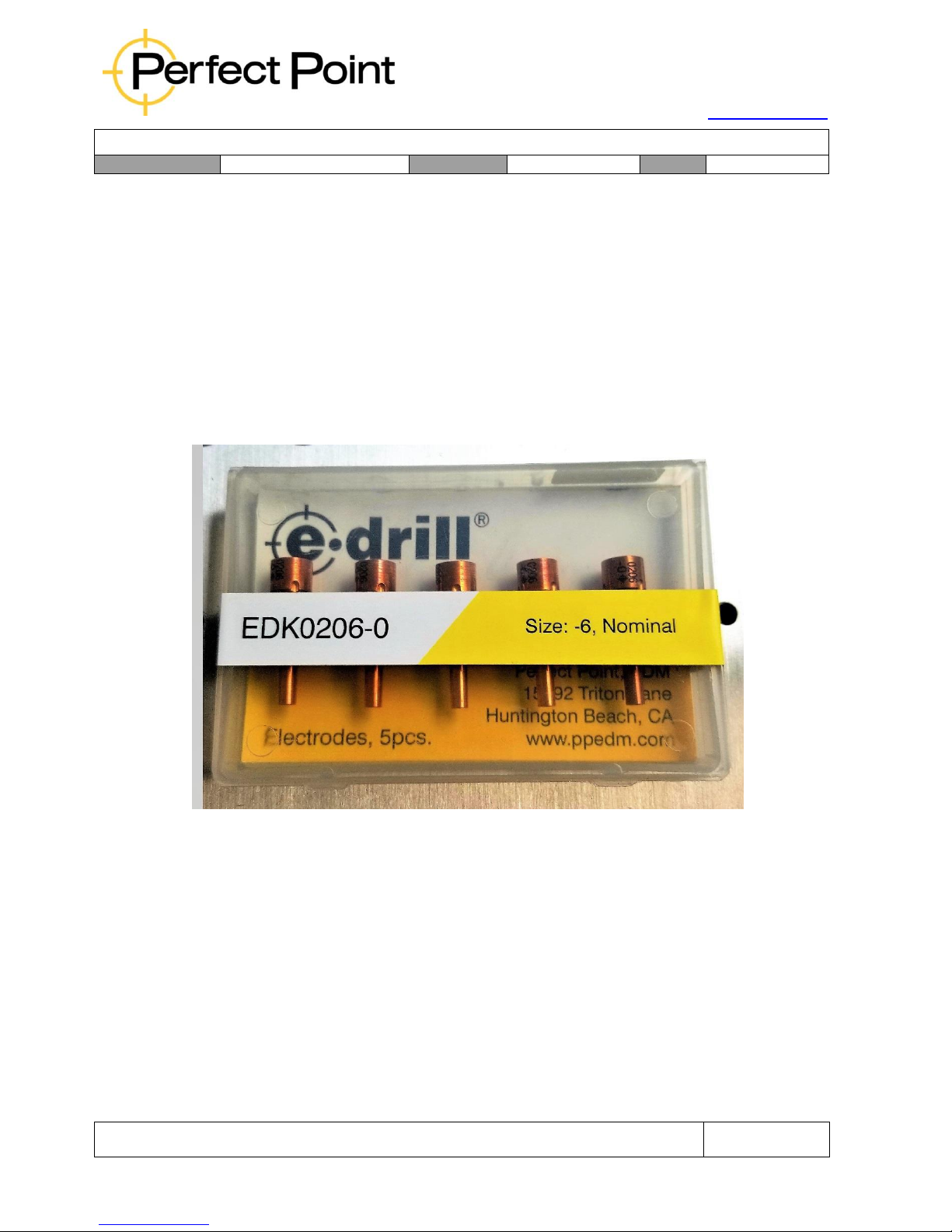
15192 Triton Lane
Huntington Beach, CA 92649
Office Tel: 714-892-3400
Hotline Tel: 714-891-6533
www.ppedm.com
User Guide
Document No.
61-101
Revision:
107
Date:
10/18/2018
This document is the property of PPedm Corp. and contains proprietary and/or patented information and may not be reproduced in
part or in whole without the express written permission of the company. Perfect Point logo, Perfect Point
TM
and E-Drill
®
are
trademarks of PPedm, Corp. US and worldwide patents pending.
Page 60 of 76
5.0
APPENDIX 2. Adapter Charts and Cross Reference Data:
The following tables, charts and cross references are supplied to provide the user with
additional information to assist with proper configuration of the E-Drill system for a particular
fastener removal project.
5.1
Electrodes:
Electrode Kits are packaged in quantities of 5 each. Each package is identified with
colored card stock for quick identification of the size range. The packaging also
provides protection for the electrodes, which may be dented or bent with rough
handling.
Standard Electrode Packaging (5 each)
5.1.1
Electrode Information:
Electrodes come in a range of standard, first, and second, oversize. Each
size is identified by a color and a “dash” size. The following chart depicts the
Electrode size range. Each material is used for specific fastener material
removal. Refer to the Operator Hand Held Terminal for recommended
Electrode use.
Page 61
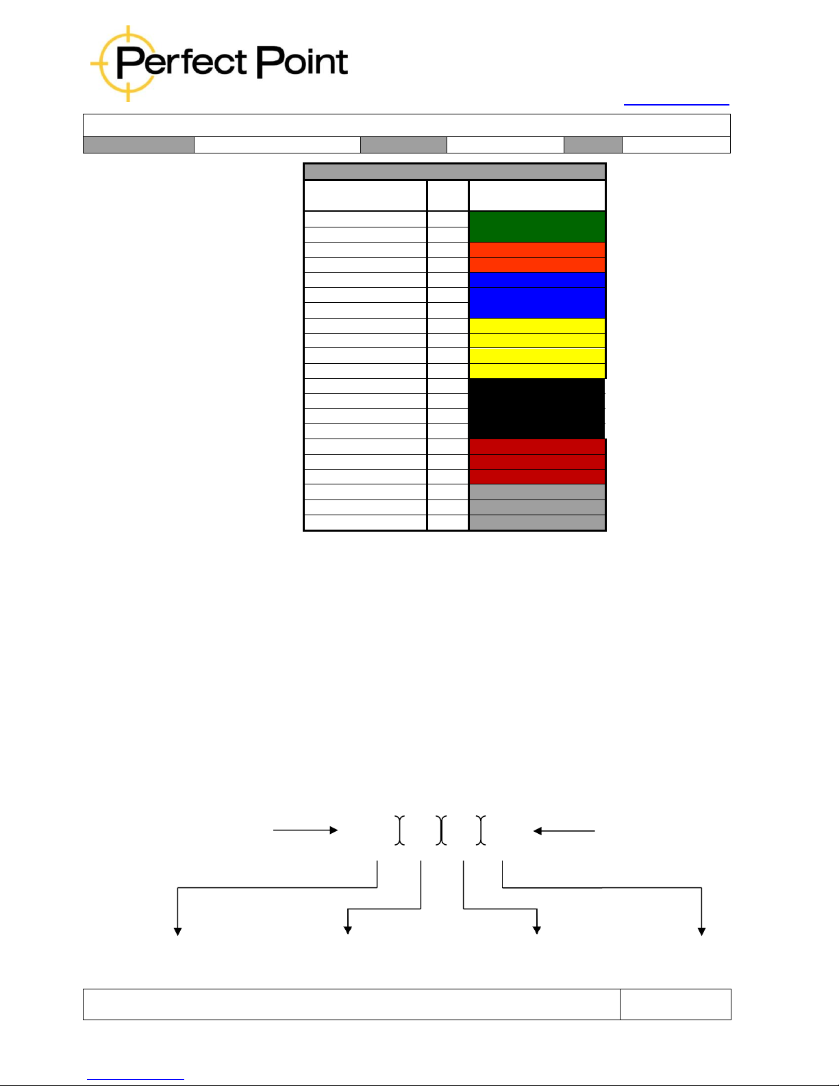
15192 Triton Lane
Huntington Beach, CA 92649
Office Tel: 714-892-3400
Hotline Tel: 714-891-6533
www.ppedm.com
User Guide
Document No.
61-101
Revision:
107
Date:
10/18/2018
This document is the property of PPedm Corp. and contains proprietary and/or patented information and may not be reproduced in
part or in whole without the express written permission of the company. Perfect Point logo, Perfect Point
TM
and E-Drill
®
are
trademarks of PPedm, Corp. US and worldwide patents pending.
Page 61 of 76
ELECTRODE PACKAGE IDENTIFICATION
Electrode Size
Dash
Size
Packaging color
3/32 Nominal
-3
GREEN Cutout Label
3/32 Plus
-3+
GREEN Cutout Label
1/8 Nominal
-4
ORANGE Cutout Label
1/8 Plus
-4+
ORANGE Cutout Label
5/32 Nominal
-5
BLUE Cutout Label
5/32 Plus
-5+
BLUE Cutout Label
5/32 1st Oversize (X)
-5X
BLUE Cutout Label
3/16 Nominal
-6
YELLOW Cutout Label
3/16 Plus
-6+
YELLOW Cutout Label
3/16 1st Oversize (X)
-6X
YELLOW Cutout Label
3/16 2nd Oversize (Y)
-6Y
YELLOW Cutout Label
1/4 Nominal
-8
BLACK Cutout Label
1/4 Plus
-8+
BLACK Cutout Label
1/4 1st Oversize (X)
-8X
BLACK Cutout Label
1/4 2nd Oversize (Y)
-8Y
BLACK Cutout Label
5/16 Nominal
-10
RED Cutout Label
5/16 1st Oversize (X)
-10X
RED Cutout Label
5/16 2nd Oversize (Y)
-10Y
RED Cutout Label
3/8 Nominal
-12
GRAY Cutout Label
3/8 1st Oversize (X)
-12X
GRAY Cutout Label
3/8 2nd Oversize (Y)
-12Y
GRAY Cutout Label
5.1.2
Electrode Material Usage:
EDK01 Series Brass Alloy Electrodes are used for Titanium fasteners above
3/16” only. BRASS ELECTRODES MUST NOT BE USED ON STEEL
FASTENERS..
EDK02 Series Copper Alloy Electrodes are used for all other fastener
materials and sizes. Refer to the home screen having selected a fastener to
double-check the electrode recommendation.
5.1.3
Electrode Part Number Legend:
Electrodes are sold in packages of 5 each. The kit part numbers aid in the
identification of electrode size, composition, and dimensions. This legend
below depicts the composition of a cutting Electrode part number.
Nomenclature EDK 02 06 - 0 Oversize
Designator
(E-Drill Electrode)
size)
E-D
rill Electrode Electrode Material Fastener Diameter Oversize Designator
(Dash “0” is exact
Page 62

15192 Triton Lane
Huntington Beach, CA 92649
Office Tel: 714-892-3400
Hotline Tel: 714-891-6533
www.ppedm.com
User Guide
Document No.
61-101
Revision:
107
Date:
10/18/2018
This document is the property of PPedm Corp. and contains proprietary and/or patented information and may not be reproduced in
part or in whole without the express written permission of the company. Perfect Point logo, Perfect Point
TM
and E-Drill
®
are
trademarks of PPedm, Corp. US and worldwide patents pending.
Page 62 of 76
Nomenclature:
EDK:
= E-Drill Electrode Kit (5 electrodes)
Electrode Material:
01 =
Brass Alloy (for most Ti fasteners)
Fastener Diameter:
02
06
=
=
Copper Alloy (for Aluminum, Inconel, Monel,
Stainless and Alloy Steel)
Fastener Stem Size Designator (3/16”)
EXAMPLE:
05 =
5/32”
Fastener
06 =
3/16”
Fastener
08 =
1/4”
Fastener
Size Designator:
All Electrodes part numbers carry a dash number indicating a nominal size (-0), or a letter
designators (-X or –Y) for each of the two over size electrode OD’s available.
•
The Letter “X” depicts the first oversize or, plus 1/64
th
of an inch.
•
The Letter “Y” depicts the second oversize or, plus 2/64
ths
(or 1/32
nd)
of an
inch).
Examples: EDK0106-0 (3/16” nominal size, brass alloy electrode)
EDK0106-X (3/16” size, plus 1/64
th
of an inch, brass alloy electrode)
EDK0206-Y (3/16” size, plus 2/64
ths
or 1/32
nd
of an inch, copper alloy
electrode).
For any fastener in the E-Drill library, the correct electrode is displayed on the home screen
after the fastener has been selected.
Note: For Cherry Max and other blind fasteners whose “nominal” shank size is
dimensionally closer to an oversize, use one oversize above the fastener size.
For example:
A 3/16” (-6) nominal alloy steel Cherry Max should be removed with the 1
st
oversize
electrode (0206-X).
A 3/16” (-6X) 1
st
oversize alloy steel Cherry Max should be removed with the 2
nd
oversize electrode (0206-Y).
Page 63
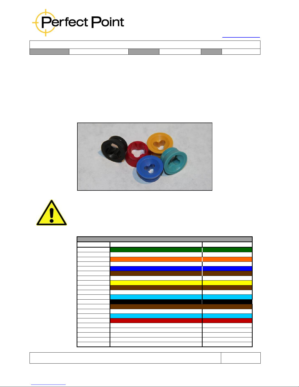
15192 Triton Lane
Huntington Beach, CA 92649
Office Tel: 714-892-3400
Hotline Tel: 714-891-6533
www.ppedm.com
User Guide
Document No.
61-101
Revision:
107
Date:
10/18/2018
This document is the property of PPedm Corp. and contains proprietary and/or patented information and may not be reproduced in
part or in whole without the express written permission of the company. Perfect Point logo, Perfect Point
TM
and E-Drill
®
are
trademarks of PPedm, Corp. US and worldwide patents pending.
Page 63 of 76
5.2
Electrode Guides:
Electrode guides are inserted into the Adapters installed on the E-Drill to steady and
center the Electrode during the cutting process. Each Guide is sized to a specific
electrode size and color coded for easy visual identification.
The same Electrode Guides are used in both the Flush Head Locator (FHL) and
Button Head Locator (BHL) systems. Electrode guides are used with their respective
Electrode applications as depicted in the chart below.
Note: Guides should be regularly inspected for damage or wear. Heavily used
Guides should be replaced every 5000 cuts (see Hand held terminal for cut counts).
Failure to replace worn guides may increase the potential for airframe damage.
This chart illustrates the Electrode Guide used with each size Electrode.
Electrode Guide and Electrode Usage
Guide P/N
Description
Electrode P/N
EDG0103-0
3/32 Electrode Guide, Nominal-Green Body
EDK0203-0
EDG0103-plus
5/32 Electrode Guide, Plus-White Body
EDK0203-plus
EDG0104-0
1/8 Electrode Guide, Nominal-Orange Body
EDK0204-0
EDG0104-plus
1/8 Electrode Guide, Plus-White Body
EDK0204-plus
EDG0105-0
5/32 Electrode Guide, Nominal-Blue Body
EDK0105-0 / EDK0205-0
EDG0105-plus
5/32 Electrode Guide, Plus- Brown Body
EDK0205-plus
EDG0105-X
5/32 Electrode Guide, 1 Oversize-White Body
EDK0105-X / EDK0205-X
EDG0106-0
3/16 Electrode Guide, Nominal-Yellow Body
EDK0106-0 / EDK0206-0
EDG0106-plus
3/16 Electrode Guide, Plus-Brown Body
EDK0206-plus
EDG0106-X
3/16 Electrode Guide, 1 Oversize-White Body
EDK0106-X / EDK0206-X
EDG0106-Y
3/16 Electrode Guide, 2 Oversize-Turquoise Body
EDK0106-Y / EDK0206-Y
EDG0108-0
1/4 Electrode Guide, Nominal-Black Body
EDK0108-0 / EDK0208-0
EDG0108-plus
1/4 Electrode Guide, Plus-Brown Body
EDK0208-plus
EDG0108-X
1/4 Electrode Guide, 1 Oversize-White Body
EDK0108-X / EDK0208-X
EDG0108-Y
1/4 Electrode Guide, 2 Oversize- Turquoise Body
EDK0108-Y / EDK0208-Y
EDG0110-0
5/16 Electrode Guide, Nominal-Red Body
EDK0110-0 / EDK0210-0
EDG0110-X
5/16 Electrode Guide, 1 Oversize-White Body
EDK0110-X / EDK0210-X
No Guide
Electrode used without a guide installed
EDK0110-Y / EDK0210-Y
No Guide
Electrode used without a guide installed
EDK0112-0 / EDK0212-0
No Guide
Electrode used without a guide installed
EDK0112-X / EDK0212-X
No Guide
Electrode used without a guide installed
EDK0112-Y / EDK0212-Y
Page 64
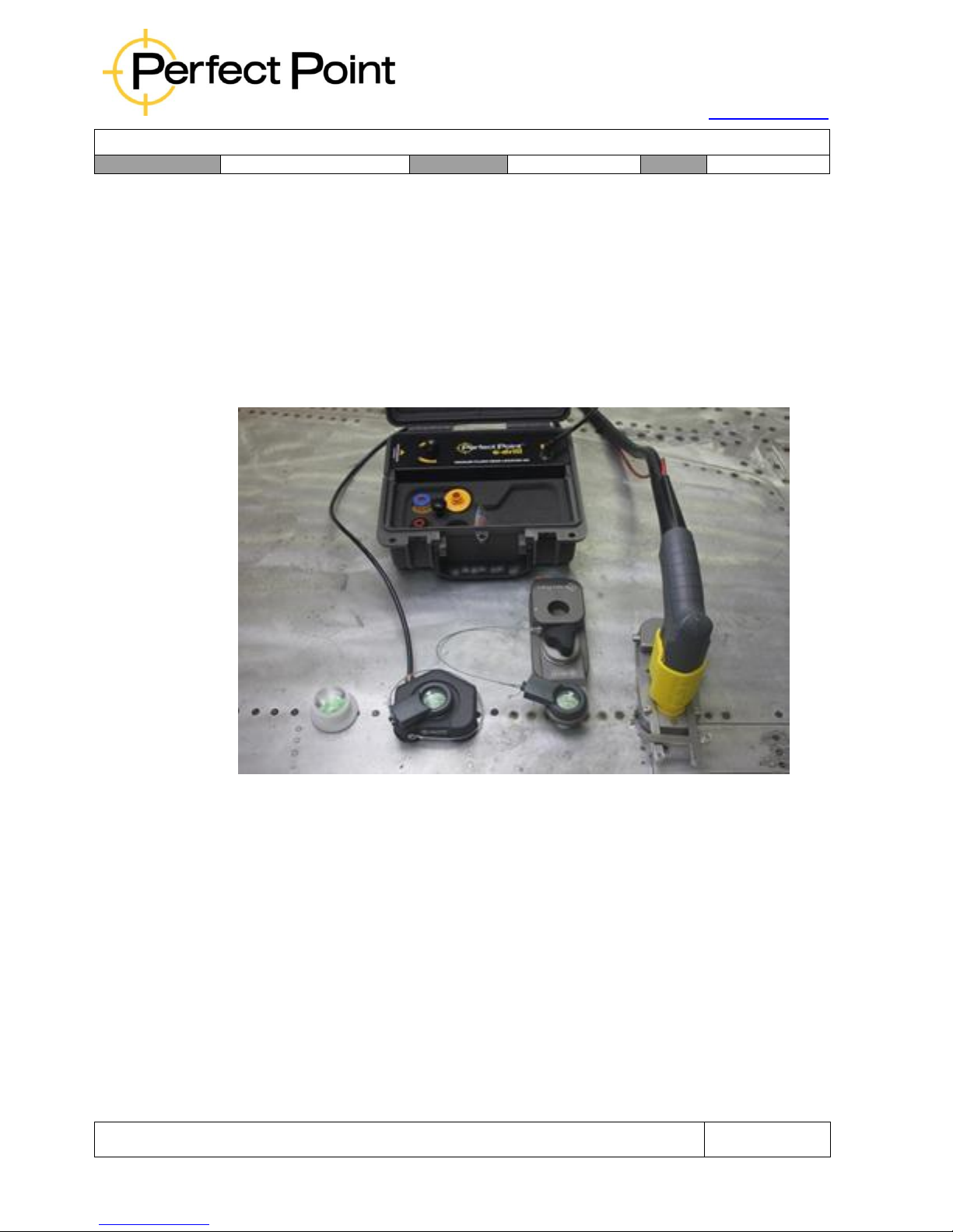
15192 Triton Lane
Huntington Beach, CA 92649
Office Tel: 714-892-3400
Hotline Tel: 714-891-6533
www.ppedm.com
User Guide
Document No.
61-101
Revision:
107
Date:
10/18/2018
This document is the property of PPedm Corp. and contains proprietary and/or patented information and may not be reproduced in
part or in whole without the express written permission of the company. Perfect Point logo, Perfect Point
TM
and E-Drill
®
are
trademarks of PPedm, Corp. US and worldwide patents pending.
Page 64 of 76
Electrode guides are also available in kits; EDG1000 is the complete electrode guide
kit for the CG Hand Tool, and EDG1010 is for the EG Hand Tool. Contact the Perfect
Point Support Hotline for details.
5.3
Flush Head Locating Systems:
E-drill recommends a precision Vacuum Flush Head Locator (VFHL) tool, for
precision removal of flush fasteners in structure to be re-used. The VFHL is also
especially developed for composite structure, where its use protects not only the
fastener hole, but also the surrounding gel-coat skin.
The standard kit (p/n EDF1321) comprises an air-driven vacuum pump, vacuum
locator and LED bomb sight. There is also a range of special vacuum locators
available for tight areas, wing edges and curved locations.
Usage of the Vacuum Locator family is covered by a separate document. Please
contact PPedm Customer Service Hotline (714.891.6533) or info@ppedm for further
details.
Page 65
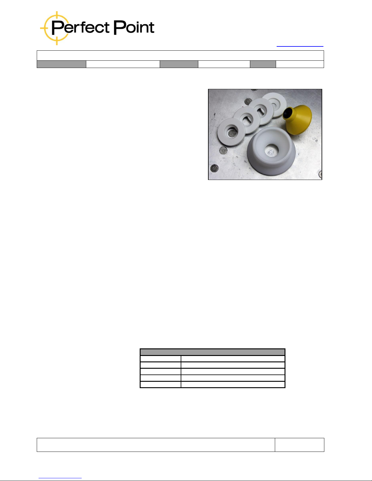
15192 Triton Lane
Huntington Beach, CA 92649
Office Tel: 714-892-3400
Hotline Tel: 714-891-6533
www.ppedm.com
User Guide
Document No.
61-101
Revision:
107
Date:
10/18/2018
This document is the property of PPedm Corp. and contains proprietary and/or patented information and may not be reproduced in
part or in whole without the express written permission of the company. Perfect Point logo, Perfect Point
TM
and E-Drill
®
are
trademarks of PPedm, Corp. US and worldwide patents pending.
Page 65 of 76
5.3.1
Universal Flush Head Locator (FHL):
The Universal Flush Head
Locator (p/n EDF0120) is
intended for skin removal
where the skin is to be
replaced, or where high
precision is not necessary
(such as where larger
fasteners are going to be
installed as replacements). The
FHL locator is a standard size
part used across the entire
FHL system. The base has a
large diameter foot to improve perpendicularity during cutting and is
recessed to accept the selected size Aperture Seal.
The FHL system is comprised of 4 basic components:
•
The Universal Flush Head Locator (FHL).
•
An Aperture seal installed in the FHL.
•
The Flush Head Adapter and Electrode guide, installed on the E-Drill
hand tool.
For environments such as fairings or wing root situations where the fasteners
are close to the edge of a crease, an FHL locator may be modified to fit, as
long as the inner-most seal is not violated.
5.3.2
Aperture Seals:
Aperture Seals are installed in the Universal Flush Head Locator and selected
to most closely match the OD of the fastener to be removed. The seal
contains the DI fluid during the cutting process. Aperture seals come in 5
different sizes depicted in the following chart.
Flush Head Locator Aperture Seals
EDF0221-300
Aperture Seal, Extra Small 0.300 Bore
EDF0221-400
Aperture Seal, Small 0.400 Bore
EDF0221-450
Aperture Seal, Medium 0.450 Bore
EDF0221-525
Aperture Seal, Large 0.525 Bore
EDF0221-675
Aperture Seal, Bombsight 0.675 Bore
Aperture seals are also available in custom sizes upon request. Please
contact PPedm Customer Service Hotline714.891.6533
5.3.3
FHL Adapter and Guide Assembly:
Page 66
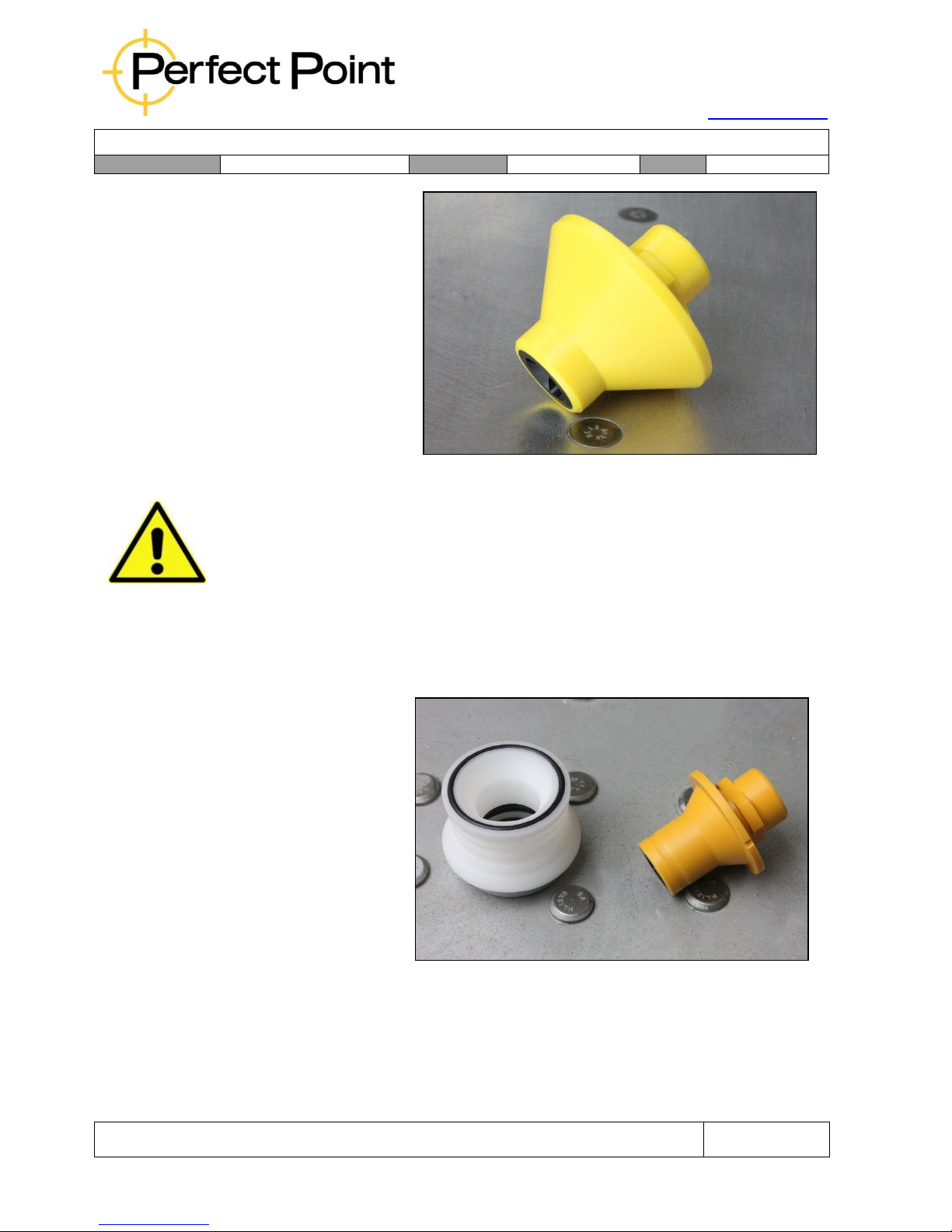
15192 Triton Lane
Huntington Beach, CA 92649
Office Tel: 714-892-3400
Hotline Tel: 714-891-6533
www.ppedm.com
User Guide
Document No.
61-101
Revision:
107
Date:
10/18/2018
This document is the property of PPedm Corp. and contains proprietary and/or patented information and may not be reproduced in
part or in whole without the express written permission of the company. Perfect Point logo, Perfect Point
TM
and E-Drill
®
are
trademarks of PPedm, Corp. US and worldwide patents pending.
Page 66 of 76
The FHL Adapter and
Guide Assembly is
installed on the end of
the E-Drill for the
selected fastener
removal application. FHL
Adapters are supplied in
both Bayonet and Tri
Wing E-Drill attachment
configurations for EG
and CG E-Drill use.
Please contact PPedm
Customer Service Hotline714.891.6533 for replacement part numbers and pricing.
Note: Adapters should be regularly inspected for damage or wear. Heavily used
Guides should be replaced every 5000 cuts (see Hand held terminal for cut counts).
Failure to replace worn guides may increase the potential for airframe damage.
5.4
Button Head Locating System:
The BHL system is comprised of 3 basic components, the Button Head Locator, the
E-Drill Adapter Assembly, including the required Electrode Guide.
•
The BHL Locator is
placed over the
Button Head
fastener on the
work surface.
•
The Button Head
Adapter is affixed
to the nose of the
E-Drill hand tool.
5.4.1
Fixed Diameter Button Head Locator (BHL) assembly:
The Button Head Locator comprises a white plastic housing, metal insert, and
three O-rings for sealing. The BHL assembly is available in two different sizes;
EDB0033 for fastener heads up to 0.5” (12.7 mm), and EDB0034 for fastener
heads larger than that.
Page 67
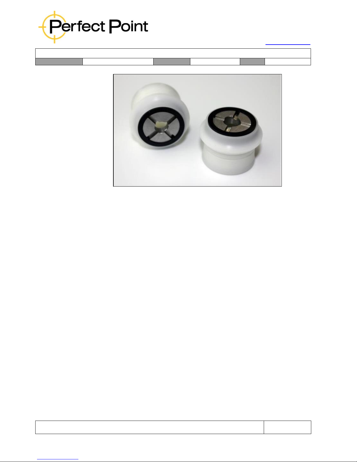
15192 Triton Lane
Huntington Beach, CA 92649
Office Tel: 714-892-3400
Hotline Tel: 714-891-6533
www.ppedm.com
User Guide
Document No.
61-101
Revision:
107
Date:
10/18/2018
This document is the property of PPedm Corp. and contains proprietary and/or patented information and may not be reproduced in
part or in whole without the express written permission of the company. Perfect Point logo, Perfect Point
TM
and E-Drill
®
are
trademarks of PPedm, Corp. US and worldwide patents pending.
Page 67 of 76
The metal inserts are removable and each is intended to be pre-drilled to suit
a specific fastener head diameter. The inserts may be supplied pre-drilled to
a specific size upon request, or the customer may purchase piloted blanks
either individually or pre-assembled, which they can drill themselves per their
requirements. The blank order numbers for smaller fasteners are EDB0033000 (complete BHL assembly) and EDB0013-000 (Insert only), and for large
fasteners are EDB0034-000 and EDB0014-000. Hexagonal inserts are also
available for specific hex-head blind fasteners, and removal of seized nuts
and bolts.
The outside diameter of BHL assemblies is optimized to fit between fastener
heads spaced per industry standard (typically greater than 4 to1, spacing to
diameter), while maximizing the footprint to enhance perpendicularity.
5.4.2
Slimline Button Head Locators:
For fasteners which are located in tight areas (such as close to ribs or
stringers) or are more tightly spaced than conventionally (engine
applications), a family of “Slimline” BHL’s is available (see below). Please
contact your distributor or the PPEDM hotline (714.891.6533) for more
information.
Page 68
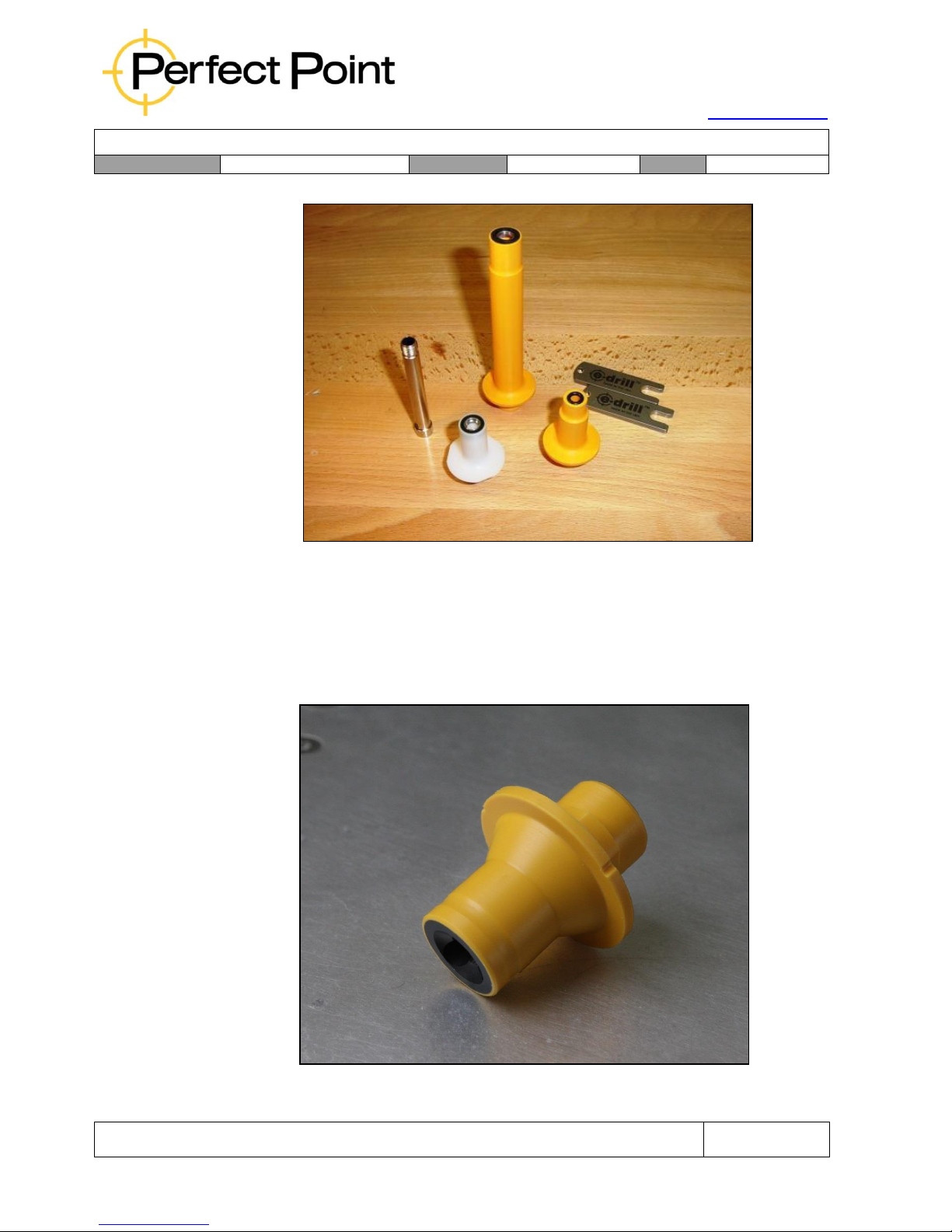
15192 Triton Lane
Huntington Beach, CA 92649
Office Tel: 714-892-3400
Hotline Tel: 714-891-6533
www.ppedm.com
User Guide
Document No.
61-101
Revision:
107
Date:
10/18/2018
This document is the property of PPedm Corp. and contains proprietary and/or patented information and may not be reproduced in
part or in whole without the express written permission of the company. Perfect Point logo, Perfect Point
TM
and E-Drill
®
are
trademarks of PPedm, Corp. US and worldwide patents pending.
Page 68 of 76
5.4.3
BHL Adapter and Guide Assembly:
The BHL Adapter and Guide Assembly is installed on the end of the E-Drill
for the selected fastener removal application. BHL Adapters are supplied in
both Bayonet and Tri Wing E-Drill attachment configurations for EG and CG
E-Drill use.
Note: See Section 1.4 Guide Extraction for Guide replacement instructions.
Button Head Adapter Assembly with Electrode Guide Installed
Page 69
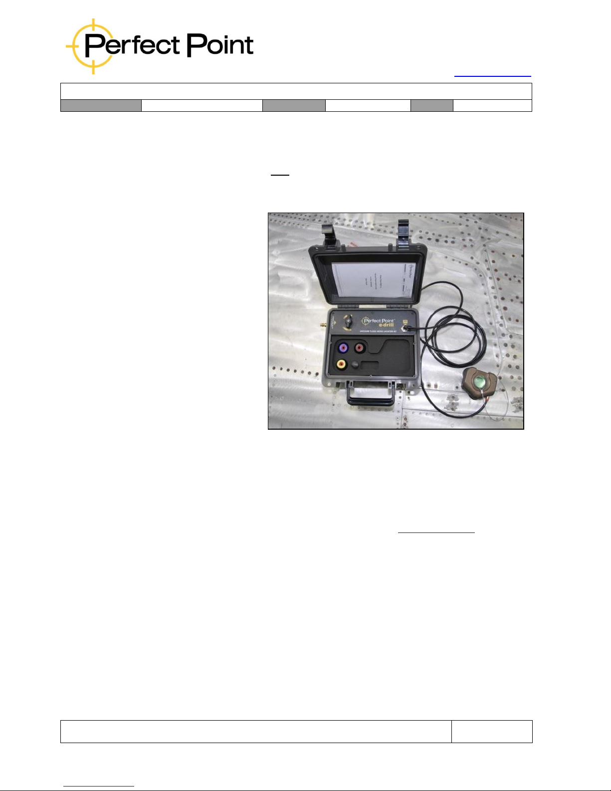
15192 Triton Lane
Huntington Beach, CA 92649
Office Tel: 714-892-3400
Hotline Tel: 714-891-6533
www.ppedm.com
User Guide
Document No.
61-101
Revision:
107
Date:
10/18/2018
This document is the property of PPedm Corp. and contains proprietary and/or patented information and may not be reproduced in
part or in whole without the express written permission of the company. Perfect Point logo, Perfect Point
TM
and E-Drill
®
are
trademarks of PPedm, Corp. US and worldwide patents pending.
Page 69 of 76
5.5
Vacuum Flush Head Locator System:
The VFHL System is specifically developed for removing flush head fasteners from
composite structure where cut accuracy is more critical than standard applications.
The VFHL system is the only tool recommended for use to remove flush fasteners
from composite structures.
The VFHL System is a completely self contained system that operates on standard
100 to 150 psi
regulated shop air
pressure. The system
comes with a 3 suction
cup Locator and
special set of VFHL EDrill Adapters and
Locators that uses
standard Electrode
Guides for centering
the Electrodes.
The Vacuum Flush
Head Locator will
operate on both
convex and concave
curved surfaces down
to a radius of
approximately 4 ft, and
on fasteners greater
than 2” from the edge of a panel. In situations with radius less than that (wing leading
edge or lip seal leading edge as examples) or where fasteners are located on the
edge of a panel, an alternative means of location might be more suitable.
5.6
Accessories - S-Blaster, Punches, Drill stands and Holsters, Toolboxes etc.
Perfect Point is continually adding accessories to the E-Drill product line, based on
customer feedback. Please visit the PPEDM web site (www.ppedm.com) or ask your
E-Drill representative for the current list of available accessories.
5.7
Custom Adapters and tooling
Custom made and specialty tools are also available from Perfect Point EDM Inc. for
difficult, hard to reach fastener locations, fastener specific kits, pilot drilling or seized
bolt removal. Contact the Customer Service number at (714-891-6533) for details
about special or custom designed tooling.
Page 70

15192 Triton Lane
Huntington Beach, CA 92649
Office Tel: 714-892-3400
Hotline Tel: 714-891-6533
www.ppedm.com
User Guide
Document No.
61-101
Revision:
107
Date:
10/18/2018
This document is the property of PPedm Corp. and contains proprietary and/or patented information and may not be reproduced in
part or in whole without the express written permission of the company. Perfect Point logo, Perfect Point
TM
and E-Drill
®
are
trademarks of PPedm, Corp. US and worldwide patents pending.
Page 70 of 76
6.0
APPENDIX 3. Trouble-Shooting Guide
This section of the User Guide lists common maintenance issues encountered and their
solutions. It is recommended that the following basic steps be accomplished before
proceeding to a higher level of trouble shooting.
To avoid problems critical maintenance items which should be checked before each shift:
o
Check for free movement of hand-tool motion over full stroke.
o
Tighten electrode using Electrode Torque Wrench.
o
For Center Ground hand-tool check Ground Pin for proper protrusion, insulation and
straightness. (Does not apply to EG Hand-tool.)
o
For External Ground hand-tool check the Ground clamp and bullet connector
condition.
In the event these basic steps do not remedy the issue, review the Troubleshooting Guide for
helpful maintenance remedies.
If a solution cannot be found in this Trouble-Shooting Guide, do not hesitate to contact the
Customer Service Hotline Phone at 714-891-6533. This number is located in 3 places on the
system for ease of access.
1.
Mobile Service Unit directly above the system power switch.
2.
The “Information” page of the “Maintenance” screen in the Hand Held
Terminal software.
3.
Printed in the header of this User Guide.
Page 71
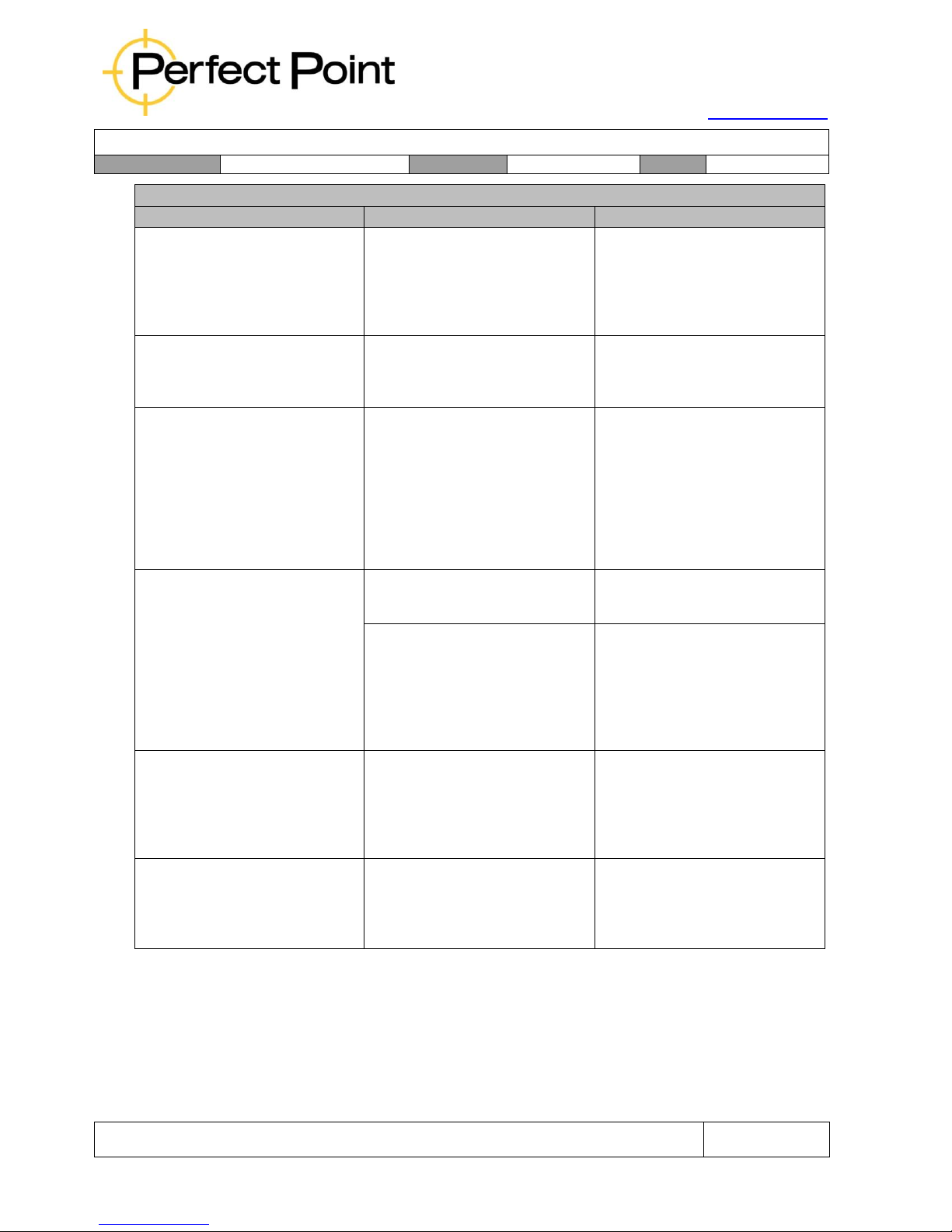
15192 Triton Lane
Huntington Beach, CA 92649
Office Tel: 714-892-3400
Hotline Tel: 714-891-6533
www.ppedm.com
User Guide
Document No.
61-101
Revision:
107
Date:
10/18/2018
This document is the property of PPedm Corp. and contains proprietary and/or patented information and may not be reproduced in
part or in whole without the express written permission of the company. Perfect Point logo, Perfect Point
TM
and E-Drill
®
are
trademarks of PPedm, Corp. US and worldwide patents pending.
Page 71 of 76
Mobile Service Unit General Fault
Trouble
Probable Cause
Remedy
No activity, no display, rear
cooling fans not working.
No input power.
Check power connection and
voltage. Check power switch is
in on position. Check facility
circuit breakers.
System displays Low
Dielectric Level error.
Dielectric water is below
minimum level.
Top-up dielectric level as
described in Section 3.4.
Initial top up routine ends
prematurely. Pressing the
button again causes more top
up, as if previous top up ended
prematurely.
Normal behavior. Since the
top-up routine is vacuum
driven, when the vacuum
stops the level drops slightly
below its previous height
during filling. Level is ok after
the initial automatic stop.
Vacuum Pump does not run
during cutting.
Supply voltage too low.
Check facility power output.
Pump damaged by flooding.
MSU requires service (see
System Overflow entry on
following page). Immediately
contact PPedm for system
service.
Mobile Service Unit makes
loud screeching noise.
Air entrapped in the Mobile
Service Unit Pressure
Regulator.
Bleed DI system (See Ch. 3
System Maintenance, Section
3.7 System Bleeding and
Charging)
System overflows during Top
Off routine causing water
puddle under the MSU.
System Sediment Tank Top
Water Level sensor is jammed.
Immediately call the PPedm
Customer Service Hotline for
assistance.
Page 72
15192 Triton Lane
Huntington Beach, CA 92649
Office Tel: 714-892-3400
Hotline Tel: 714-891-6533
www.ppedm.com
User Guide
Document No.
61-101
Revision:
107
Date:
10/18/2018
This document is the property of PPedm Corp. and contains proprietary and/or patented information and may not be reproduced in
part or in whole without the express written permission of the company. Perfect Point logo, Perfect Point
TM
and E-Drill
®
are
trademarks of PPedm, Corp. US and worldwide patents pending.
Page 72 of 76
E-Drill General Fault
Trouble
Probable Cause
Remedy
No cutting occurs, vacuum
pump does not start.
Electrode needs replacement.
Green light on hand-tool is
flashing.
Replace electrode (see
Section 2.1).
System error. Flashing red
light on hand-tool.
Observe error displayed on
control terminal. Check water
level. Contact the PPedm
Customer Service Hotline for
support.
Hand-tool not connected to
utility cabinet.
Recheck hand-tool connection
on rear of cart. Ensure locking
bezel is fully rotated.
No cutting occurs, vacuum
pump starts but pressure
pump does not start.
Fastener surface is not
conductive.
Check that nose of hand-tool
is placed over fastener, and all
paint or sealant has been
removed from fastener
surface.
CG Hand Tool will not cut.
Ground pin incorrectly
adjusted or damaged.
EG Hand Tool will not cut
Check for bad or loose ground
clamp connection.
Cutting occurs but system
shows red warning LED at end
of cut.
Hand-tool trigger was released
prematurely.
Re-cut fastener ensuring to
hold down trigger until system
finishes cutting.
Cutting process ended
prematurely.
Check library setting for
correct fastener type. Make an
additional cut by squeezing
trigger a second time while still
in-place over fastener. The
system will likely repeat the
same error since less cutting
was required in the second
cycle.
Page 73
15192 Triton Lane
Huntington Beach, CA 92649
Office Tel: 714-892-3400
Hotline Tel: 714-891-6533
www.ppedm.com
User Guide
Document No.
61-101
Revision:
107
Date:
10/18/2018
This document is the property of PPedm Corp. and contains proprietary and/or patented information and may not be reproduced in
part or in whole without the express written permission of the company. Perfect Point logo, Perfect Point
TM
and E-Drill
®
are
trademarks of PPedm, Corp. US and worldwide patents pending.
Page 73 of 76
E-Drill General Fault
Trouble
Probable Cause
Remedy
Cutting not to depth. Water
leaking around tip.
Hand-tool not firmly and
consistently held in contact
with fastener and airframe
surface throughout cut.
Press hand-tool firmly over
fastener and maintaining
pressure until cut is complete.
Cycle time excessively long.
Cutting too deep.
Hand-tool is not held stable
during cut.
Hold hand-tool in a fixed
position during cutting.
Electrode is not tight.
Tighten electrode.
Cut slower than expected.
Electrode is not tight.
Check electrode tightness with
electrode torque wrench.
Ground Pin protrusion not
sufficient, restricting water flow
and/or causing bad ground
connection.
Adjust Ground Pin protrusion
with Ground Pin Setting Tool.
Air in system.
Bleed DI system.
Leaks in water system.
Check visually for leaks in
water system or for crimped
hoses. If you have access to a
pressure gauge then check
water pressure (see section
3.8, page 48.)
Wrong fastener selected.
Check fastener settings.
Wrong electrode type.
Check electrode material
application.
Operator error.
User lifted or moved E-Drill
during cut sequence.
Page 74

15192 Triton Lane
Huntington Beach, CA 92649
Office Tel: 714-892-3400
Hotline Tel: 714-891-6533
www.ppedm.com
User Guide
Document No.
61-101
Revision:
107
Date:
10/18/2018
This document is the property of PPedm Corp. and contains proprietary and/or patented information and may not be reproduced in
part or in whole without the express written permission of the company. Perfect Point logo, Perfect Point
TM
and E-Drill
®
are
trademarks of PPedm, Corp. US and worldwide patents pending.
Page 74 of 76
E-Drill General Fault
Trouble
Probable Cause
Remedy
Water sprays excessively
out of hand-tool. Hand-tool
cannot be held easily
against work surface
Dielectric vacuum and water
connections incorrect.
Check water tube connections.
Tube connections at back of
utility cabinet should not be
crossed.
No cutting occurs. No water
evident. Burning smell
around electrode
Wrong Adapter in use for the
fastener being removed
resulting in the ground pin not
being depressed sufficiently –
typically a button-head tip is
being used for a flush head
fastener. Incorrectly adjusted
or damaged Ground Pin.
Select the correct tip Adapter
configuration for the fastener.
If the wrong tip is used then
the depression of the ground
pin will not be sufficient for
water flow, causing
overheating and damage to
the equipment.
Page 75
15192 Triton Lane
Huntington Beach, CA 92649
Office Tel: 714-892-3400
Hotline Tel: 714-891-6533
www.ppedm.com
User Guide
Document No.
61-101
Revision:
107
Date:
10/18/2018
This document is the property of PPedm Corp. and contains proprietary and/or patented information and may not be reproduced in
part or in whole without the express written permission of the company. Perfect Point logo, Perfect Point
TM
and E-Drill
®
are
trademarks of PPedm, Corp. US and worldwide patents pending.
Page 75 of 76
E-Drill General Fault
Trouble
Probable Cause
Remedy
E-Drill stops within a second of
starting, and does not go to
cut depth.
Ground Pin protrusion
significantly out of adjustment
or worn beyond its life.
Paint, corrosion, or sealant on
fastener head.
Adjust Ground Pin protrusion
with Ground Pin Setting Tool.
Clean fastener head for proper
grounding.
Cutting a depressed center
fastener (such as a Torx or
Phillips head) without specially
adjusting the Ground Pin
protrusion to match the
fastener depth.
Electrode advances to limit
and Hand Tool emits a
constant buzzing noise.
E-Drill Trigger is stuck in the
on position.
Power off system. Check
operation of trigger, clean
surrounding area to attempt to
free the trigger assembly.
Trigger should “click” when
depressed. Contact PPedm
Customer Service Hotline if
the problem persists.
Cutting is intermittent and
Electrode has come loose in
Remove Adapter, drive
cutting time is longer than
E-Drill.
electrode forward using the
usual.
trigger and re-tighten with the
electrode torque tool.
Water leaking from E-Drill
retract button or ground pin
adjusting holes.
E-Drill seal failure
Call the PPedm Customer
Service Hotline and obtain an
RMA and return E-Drill to
PPedm for service.
Vacuum pump does not stop
Water inside of E-Drill.
Call the PPedm Customer
operating after 3 seconds of
Service Hotline and obtain an
trigger release. E-Drill
RMA and return E-Drill to
“buzzing” and does not stop
PPedm for service.
automatically at the end of
stroke.
Page 76
15192 Triton Lane
Huntington Beach, CA 92649
Office Tel: 714-892-3400
Hotline Tel: 714-891-6533
www.ppedm.com
User Guide
Document No.
61-101
Revision:
107
Date:
10/18/2018
This document is the property of PPedm Corp. and contains proprietary and/or patented information and may not be reproduced in
part or in whole without the express written permission of the company. Perfect Point logo, Perfect Point
TM
and E-Drill
®
are
trademarks of PPedm, Corp. US and worldwide patents pending.
Page 76 of 76
E-Drill General Fault
Trouble
Probable Cause
Remedy
Fastener does not punch out.
Wrong fastener settings.
Check all settings in the HHT.
Wrong electrode type.
Check electrode application
against fastener application.
Insufficient cut depth
programmed in HHT library.
Check fastener size.
Oversize fastener.
If problem persists, contact
PPedm Customer Service
Hotline for assistance.
User Error
User lifted hand-tool during cut
sequence.
 Loading...