

Page 1

Manual # P80173002H- Date:2008/03/25
OPERATOR'S MANUAL
Dual Purpose Electric Grill
246563
Model LE1808CA
This dual purpose grill can be used as a portable model or attached to the included grill cart as shown above right.
Printed in China
NOTE TO ASSEMBLER/ INSTALLER:
Leave this manual with the consumer.
NOTE TO CONSUMER:
Keep this manual for future reference.
RECORD YOUR SERIAL #__________________
(Seerating label on grill)
IMPORTANT:
FREE HELP
FROM THE GRILL EXPERTS
Do not return to thestore. At GrandHall we're
the experts on this product and trained to help
you with:
visit
www.grandhall.com or call:
1- 877-550-8041
Monday - Friday 8:00am-4:30pm CST
Assembly questions
Grilloperation
Replacement of damaged ormissingparts
WARNING
! !
Failure to comply with these instructions could
result in a fire or electric shock that could cause
serious bodily injury, death or property damage.
FOR OUTDOOR USE ONLY. DO NOT USE
INDOORSOR FOR COMMERCIALCOOKING.
Whether this grill was assembled by you or someone else, you must read this entire manual
before using your grill to ensure the grill is
properly assembled, installed and maintained.
Yourgrillwillgetveryhot.Always wear a flame
retardant BBQ mitt when cooking on your grill.
Never leanovercooking areas while usinggrill. Do
not touch cooking surf aces, lid, grill housing or
other parts while grill isin operation, or until thegrill
has cooled down after use.
Use your grill atleast 2 feet away from anywall
orsurface.Use your grill at least 2 feetaway from
combustible objects that can melt or catch fire
(such as vinyl or wood siding, fences and overhangs) or sources of ignition including pilot lights
on water heaters and live electrical appliances.
Page 2
2
Table of Contents
Primary Safety Warnings ........................... 1-3
Pre-Assembly Instructions.............................. 3
Part Diagrams and Lists .......................... 4-6
Assembly Instructions...............................7-12
Use and Care Instructions ........................ 13
Troubleshooting .............................................. 14
Cleaning and Maintenance .......................... 15
Cooking Chart .............................................. 16
Warranty Terms ..............................
Back Cover
•
•
A short power-supply cord (or detachable
power-supply cord) is to be provided to reduce
the risk resulting from becoming
entangled in or tripping over a longer cord.
Longer detachable power-supply cords or
extension cords are available and may be
used if care is exercised in their use.
If a longer detachable power-supply cord or
extension cord is used:
1) The marked electrical rating of the cord set
or extension cord should be at least as great
as the electrical rating of the appliance, and
2) The cord should be arranged so that it will
not drape over the countertop or tabletop
where it can be pulled on by children or
tripped over.
3) The appliance is of the grounded type, the
extension cord should be a grounding-type 3wire cord.
Outdoor extension cords should be used with
outdoor use products and are surface
marked with suffix letters "W-A"and with a
tag stating "Suitable for Use with Outdoor
Appliances". The connection to an extension
cord should be kept dry and off the ground.
Store products indoors when not in use – out
of the reach of children.
Do not clean this product with a water spray
or the like.
When using this grill or any electrical appliances,
basic safety precautions should always be
followed including the following.
IMPORTANT SAFEGUARD
•
Read all Instructions.
Do not touch hot surfaces. Use handles or
knobs.
To protect against electrical shock do not
immerse cord, plugs, or this grill in water or
other liquid.
Close supervision is necessary when any
appliance is used near children.
Unplug from outlet when not in use and
before cleaning . Allow to cool before putting
on or taking off parts.
Do not operate any appliance with a damaged cord or plug or after the appliance
malfunctions or has been damaged in any
manner. Return appliance to the nearest
authorized service facility for examination,
repair, or adjustment.
The use of accessory attachments not
recommended by the appli ance manufacturer
may cause injuries.
Do not let cord hang over edge of table or
counter, or touch hot surfaces.
Do not place on or near a hot gas or
electrical burner, or in a heated oven.
Extreme caution must be used when moving
an appliance containing hot oil or other hot
liquids.
Attach the plug of the appliance to the
receptacle of power supply extension cord
first, then plug cord into the wall outlet.
To disconnect, turn any control to “off”, then
remove plug from wall outlet.
Do not use appliance for other than intended
use.
Fuel, such as charcoal briquettes, is not
to be used with appliance.
Use only on properly grounded outlet.
•
•
•
•
•
•
•
•
•
•
•
•
•
•
! !
Failure to read and follow the Use and
Care Instructions could result in a fire or
explosion that could cause serious bodily
injury, death or property damage.
WARNING
IMPORTANT
Remove the Grease Receptacle BEFORE detaching the Grill Head for portable or table-top use.
Reinstall the Grease Receptacle once the Grill
Head is firmly in position (with legs opened and
placed on a flat surface).
SAVE THESE
INSTRUCTIONS
•
•
•
Page 3
3
USE AND SAFETY
The use of an extension cord is not recommended with this grill.
Grill is rated for 1,700 watts at 120VAC.
If you must use an extension cord, for
your safety: Use only outdoor extension
cords marked with suffix letters "W-A" and
with a tag stating "Suitable for Use with
Outdoor Appliances".
Do not use 16 or 18 gauge extension cords
with your electric grill. Damage to household
wiring and/or fire could result.
DO NOT USE CHARCOAL OR ANY
TYPE FUEL INSIDE THIS GRILL. Using
charcoal or fuel will damage your grill
and result in a fire or explosion that
could cause serious bodily injury,
death or property damage.
Brass components, such as the rheostat
valve stem used on this electric grill,
contain lead which is known to the
State of California to cause cancer, bi rth
defects, or other reproductive harm.
!
WARNING
!
•
•
•
•
•
•
•
•
•
GROUND FAULT INTERRUPTER REQUIRED
Since 1971 the National Electric Code (NEC)
has required Ground Fault Circuit Interrupter
devices on all outdoor circuits.
If your residence was built before 1971, check
with a qualified electrician to determine if a
Ground Fault Circuit Interrupter protector exists.
Do not use this appliance if the circuit does
not have GFCI protection.
Do not plug this grill into an indoor electrical
circuit.
Connect cord to properly grounded GFCI
(Ground Fault Circuit Interrupter) outlet only.
Never operate your electric grill when it is
raining.
Always keep cord dry and off the ground.
Never put the cord or heating element in water
or any liquid.
To prevent your grill from being splashed by
water or falling into water, do not use grill
within 10 feet of pool, spa, pond, water faucet
or any body of water.
Make sure the control knob is set to OFF
before plugging OR unplugging your grill.
Unplug your grill when not in use or before
moving the grill.
Do not unplug your grill by pulling the cord.
Keep cord away from hot grill surfaces.
Never operate your grill if the cord or plug
appears damaged.
Never remove the grounding plug or use with
an adapter to two prongs.
Unplug the cord before using water or any
liquid to clean your grill.
•
•
•
•
•
•
•
•
•
•
•
•
ELECTRIC SHOCK CAN KILL OR RESULT IN
SERIOUS INJURY.
TO PREVENT ELECTRICAL SHOCK:
DANGER
!!
Save These Instructions
for Future Reference
•
Grill Information Center
1-877-550-8041
8am-4:30pm CST, Monday through Friday
PRE-ASSEMBLY
Read and performthe followingpre-assemblyinstructions:
•
•
•
Open lid of shipping carton and remove parts box and
packing materials. Lay cardboard sheet on floor and
use as a work surface to protect floor and grill parts
from scratches.
You may slice the carton front corners with a utility
knife to lay open the carton front panel. This allows
you to raise the grill head lid and remove the components packed inside, making it easier to lift. Use the
sliced off carton front as a work surface to protect
floor and grill parts from scratches.
Use the Hardware and Part Diagrams to ensure all
items are included and free of damage.
Do not assemble or operate the grill if it appears
damaged. If there are damaged or missing parts
when you unpack the shipping box or you have
questions during the assembly process, call the
For your safety, obtain assistance from another
person when assembling this gas grill.
Tools Requiredfor Assembly:
protective work gloves
#2 & #3 Phillips Head Screwdriver
California Proposition 65
Page 4
4
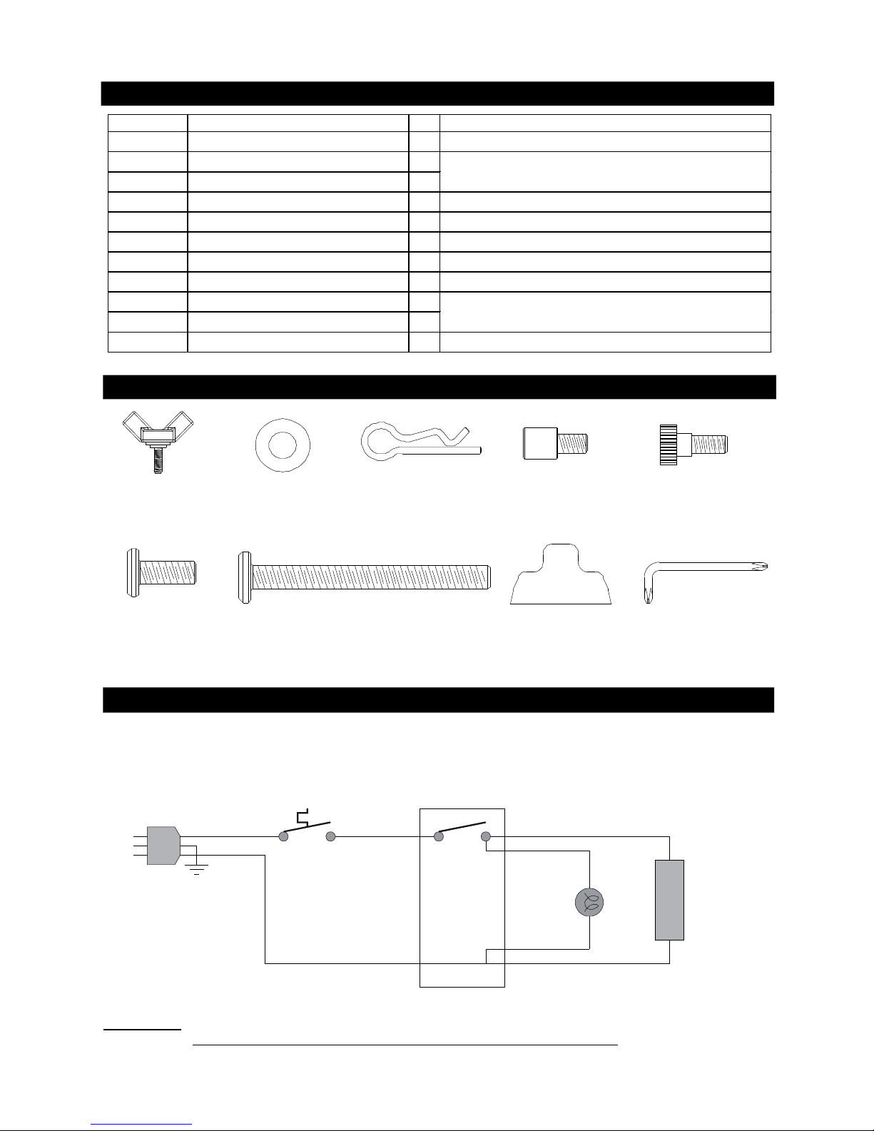
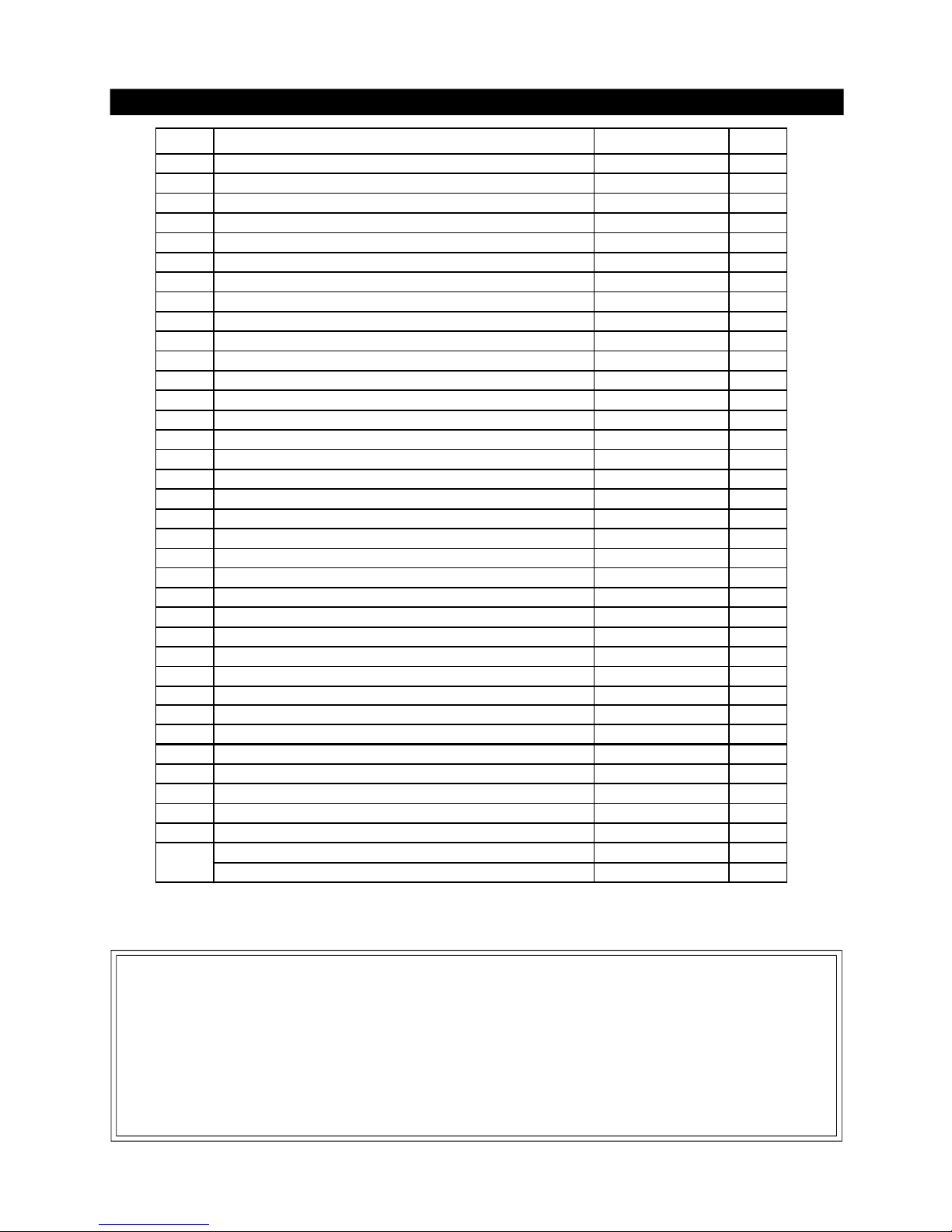
Hardware Pack Diagram for Model LE1808CA
Hardware Pack Parts List for Model LE1808CA
Specification and Wiring Diagram
AC Power Rate: 120 VAC / 60 Hz, 1,700 Watts
Temperature Setting Range: 120°F ~570°F
•
•
WARNING
: If any of the original wire supplied with the appliance needs to be replaced,
it must be replaced with specified type as above or its equivalent
.
AC120V/60Hz
Green/AW G14/105°C Chass is
White/AWG14/105°C
Black/AWG14/105°C
White/AWG14/105°C
White/AWG18/105°C
Black/AWG18/105°C
White/AWG14/200°C
Black/AWG14/200°C
Heat Element
120VAC/1,700Watt
Indicator
120VAC
Electric Timer
Module
Thermostat
120°F~570°F
PART # PART DESCRIPTION QTY PURPOSE OF PART
P06027002A Hardware Pack 1 For use in assem bly of Model LE1808CA
P05501106B
Cotter Pin 2
S411G07012
Washer 7/16 in. 2
S112G04324
Phillips Head Screw 1/4 in. X 2 in. 8 Attaches Cart Bottom Shelf between Cart Legs
S112G04084
Phillips Head Screw 1/4 in. x1/2 in. 8 Attaches Bowl Brackets to Upper Cart Legs
S112G04084
Phillips Head Screw 1/4 in. x 1/2 in. 8 Attaches Side Shelf Bracket to Cart Legs
S233G04104 Wing Bolt 1/4 in. x 5/8 in. 6 Attaches Grill Head onto Bowl Bracket
PD13010050
Control Knob for Electric Burner 1 Attaches to Control Panel
S138G04104
Pattern Head Screw 1/4 in. x 5/8 in. 8
P05515020B
"L" Screwdriver 1
S193G04074
Special Flat Head Screw 1/4 in. x7/16 in. 2 Attaches to Grease TrayBracket
Attaches Wheel Axle and Wheels to Cart Legs
Attaches Side Shelf to Side Shelf Bracket
Control Knob for
Electric Burner
Qty. 1
Part # PD13010050
Scale: 1:2
Wing Bolt
1/4 in. x 5/8 in.
Qty. 6
Part # S233G04104
Washer 7/16 in.
Qty. 2
Part # S411G07012
Pattern Head Screw
1/4 in. x 5/8 in.
Qty. 8
Part # S138G04104
Phillips Head Screw
1/4 in. x 1/2 in.
Qty. 16
Part # S112G04084
Phillips Head Screw
1/4 in. x 2 in.
Qty. 8
Part # S112G04324
Cotter Pin
Qty. 2
Part # P05501106B
Special Flat Head Screw
1/4 in. x 7/16 in.
Qty. 2
Part # S193G04074
"L" Screwdriver
Qty. 1
Part # P05515020B
Scale: 1:2
Page 5
5
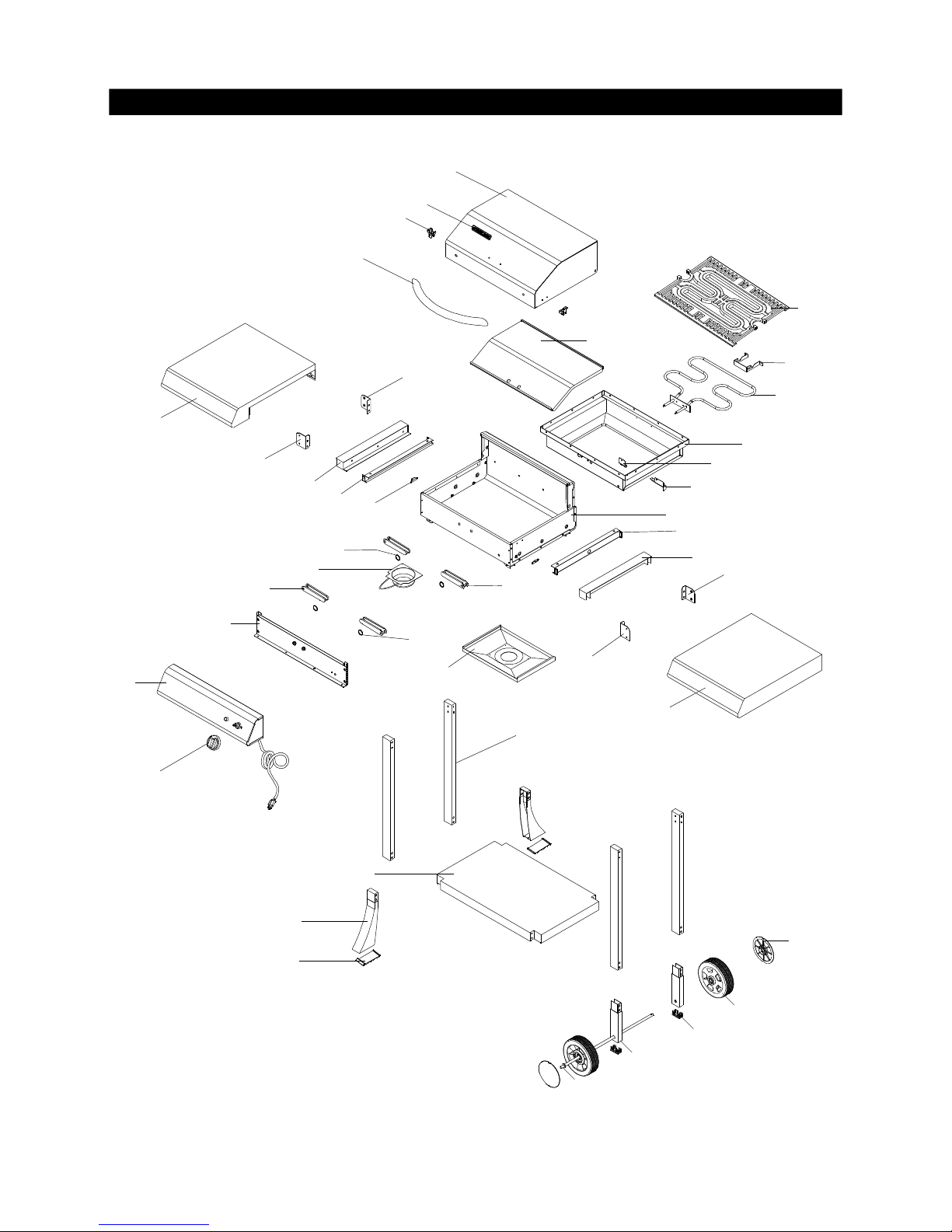
Parts Diagram for Model LE1808CA
1
5
3
4
10
13
9
8
11
7
21
20
17
18
14
15
16
6
27
28
34
33
31
30
32
24
23
25
26
18
17
24
23
29
19
2
22
12
21
22
35
Page 6
Parts List for Model LE1807CA
6
Important: Use only Grand Hall certified replacement parts. The use of any part that is not a factory
authorized part can be dangerous and will also void your product warranty. Keep this Operator's Manual
for convenient referral and for part replacement.
To Order Grand Hall Certified Replacement Parts, Call 1-877-550-8041
To o btain the correct replacement parts for your electric grill, please refer to the part numbers in this parts
list. The following information is required to ensure you receive the correct parts:
1. Model and Serial Number (see UL lab el on grill)
2. Part Number
3. Part Description
4. Quantity of parts needed
Parts List for Model LE1808CA
KEY PART DESCRIPTI ON PART # QTY
1 Lid PD01010015 1
2 Lid Trim P late PD01020012 1
3 Lid Handle PD02010015 1
4 Name Plate P00414041C 1
5 Lid Latch, Upper PD03010011 2
6 Lid Latch, Lower PD03020011 2
7 Bowl, Outer PD04010015 1
8 Bowl, Inner PD04020012 1
9 Burner, Electric PD05010010 1
10 Cooking Grid PD07010013 1
11 Thermostat Bracket PD08010025 1
12 Thermostat Protector PD08010042 1
13 Burner Bracket PD16010025 1
14 Control Panel Heat Shield PD08010015 1
15 Control Panel Assembly PD09010015 1
16 Control Knob PD13010050 1
17 Leg, Foldable PD17030015 4
18 Leg Grip PD17040015 4
19 Grease Draining Tray PD14010012 1
20 Grease Receptacl e PD14020012 1
21 Grease Tray Bracket PD16040015 2
22 Bowl Bracket PD16010042 2
23 Side Shelf Bracket, LF/RR PD16030032 2
24 Side Shelf Bracket, RF/LR PD16030042 2
25 Side Shelf, Left PD19010022 1
26 Side Shelf, Right PD19020022 1
27 Cart Leg, Upper PD17010032 4
2
8
Cart Bottom Shelf PD20010012 1
29 Cart Leg, Lower Left PD17020012 2
30 Cart Leg, Lower Right PD17020032 2
31 End Cap, Leg PD21010010 2
32 Wheel Axl e PD18010015 1
33 Wheel P05101001A 2
34 Wheel Hub Cap P05116001B 2
35 Cart Leg Protective Pad, Lower Left PD17020056 2
Hardware Pack P06027002A 1
Operator's Manual P80173002H 1
Note: This grill can be assembled in approximately 30 minutes.
Page 7
7
Assembly Instructions
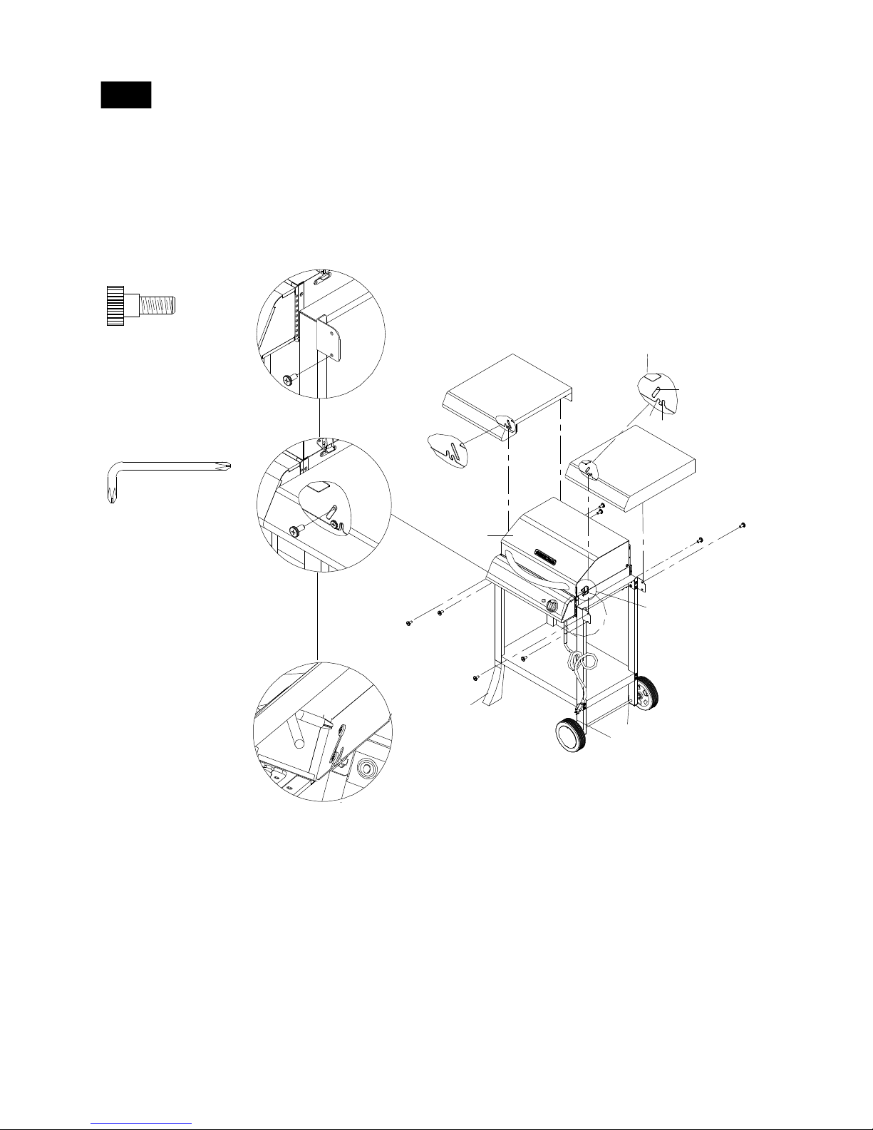
1
2
Cotter Pin
Qty. 2
Part # P05501106B
Washer 7/16 in.
Qty. 2
Part # S411G07012
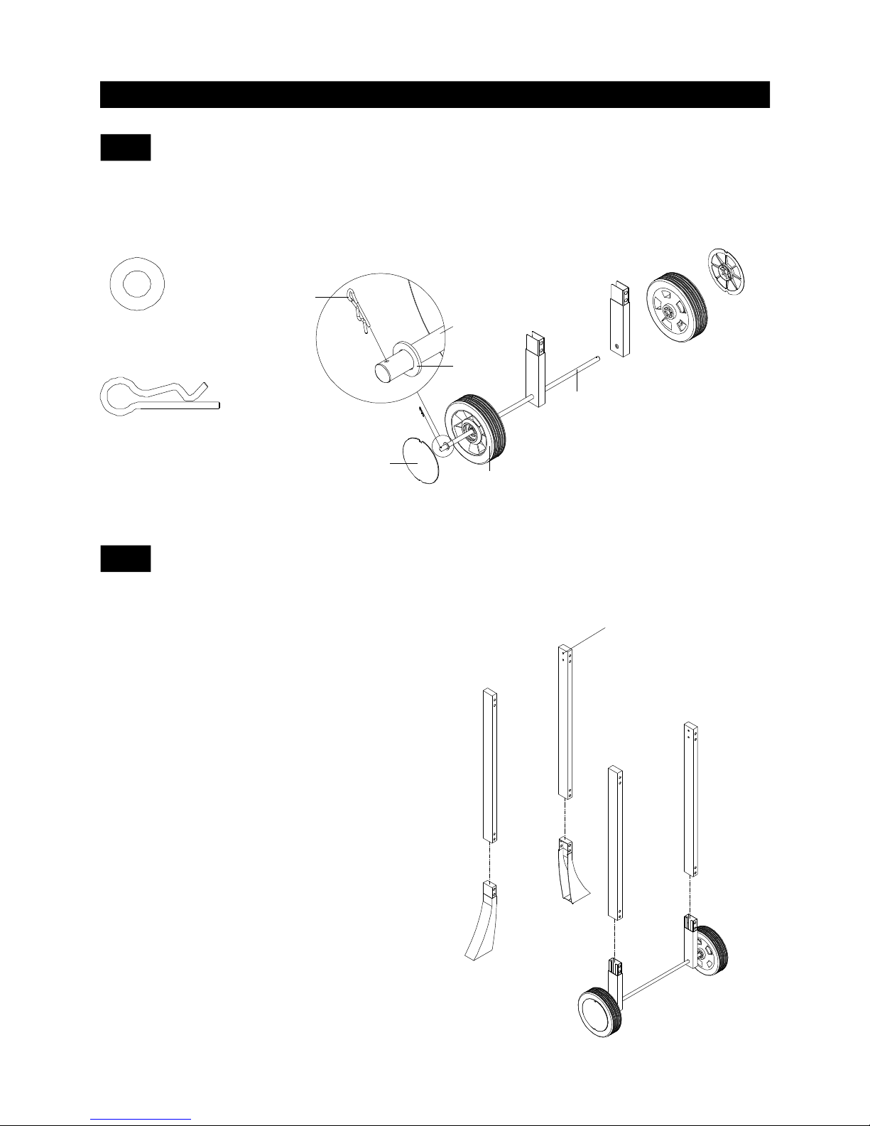
Install Cart Legs (Fig. 2)
Install Wheel (Fig. 1)
Fig. 1
Fig. 2
1.
2.
3.
4.
1.
2.
Lower Left
Cart Legs
Wheel
Hub Cap
Wheel
Axle
Wheel
Wheel
Axle
Washer
Cotter
pin
Lower Left
Cart Legs
Upper Left
Cart Legs
Upper Right
Cart Legs
Lower Right
Cart Legs
Double holes
face inward
Thread W heel Axle on the Lower Front Left Cart Legs.
Insert1Wheeland1Washer7/16in.totheleftsideof
Wheel Axle and secure Cotter Pin as shown.
Snap the Wheel Hub Caps onto the W heels.
Repeat steps for the rear right side of Wheel Axle.
Align the 2 holes on the Lower Right Cart Legs with the
threaded holes on the Upper Right Cart Legs and snap
fit the two parts together.
Repeat Steps for Upper Left Cart Legs and Lower Left
Cart Legs.
Page 8
Upper Left
Cart Legs
Upper Right
Cart Legs
Lower Right
Cart Legs
Lower Left
Cart Legs
Cart Bottom Shelf
Double holes
face inward
8
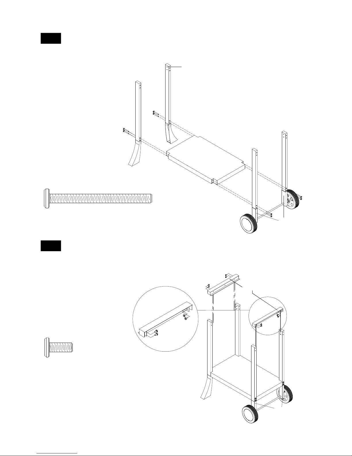
3
Phillips Head Screw
1/4 in. x 2 in.
Qty. 8
Part # S112G04324
Install Cart Bottom Shelf (Fig. 3)
Install Bowl Brackets (Fig. 4)
Phillips Head Screw
1/4 in. x 1/2 in.
Qty. 8
Part # S112G04084
Fig. 3
Fig. 4
1.
2.
1.
2.
3.
Lower Left
Cart Legs
Upper Left
Cart Legs
Left Bowl
Bracket
Right Bowl
Bracket
Cart Bottom
Shelf
Lower Right
Cart Legs
Flat plate f aces inward
Right Bowl
Bracket
4
Attach the Cart Bottom Shelf between the Cart Legs (as
shown).
Note: Ensure double holes face inward on 4 Cart Legs.
Insert 2 Phillips Head Sc rew s 1/4 in. x 2 in. per Cart Leg
and tighten securely.
Attach a Right Bowl Bracket between the Upper Right Cart
Legs.
Note: Ensure flat plate faces inward.
Insert 4 Phillips Head screws 1/4 in. x 1/2 in. and tighten
securely.
Repeat steps for Left Bowl Bracket between the Upper
Left Cart Legs.
Page 9
9
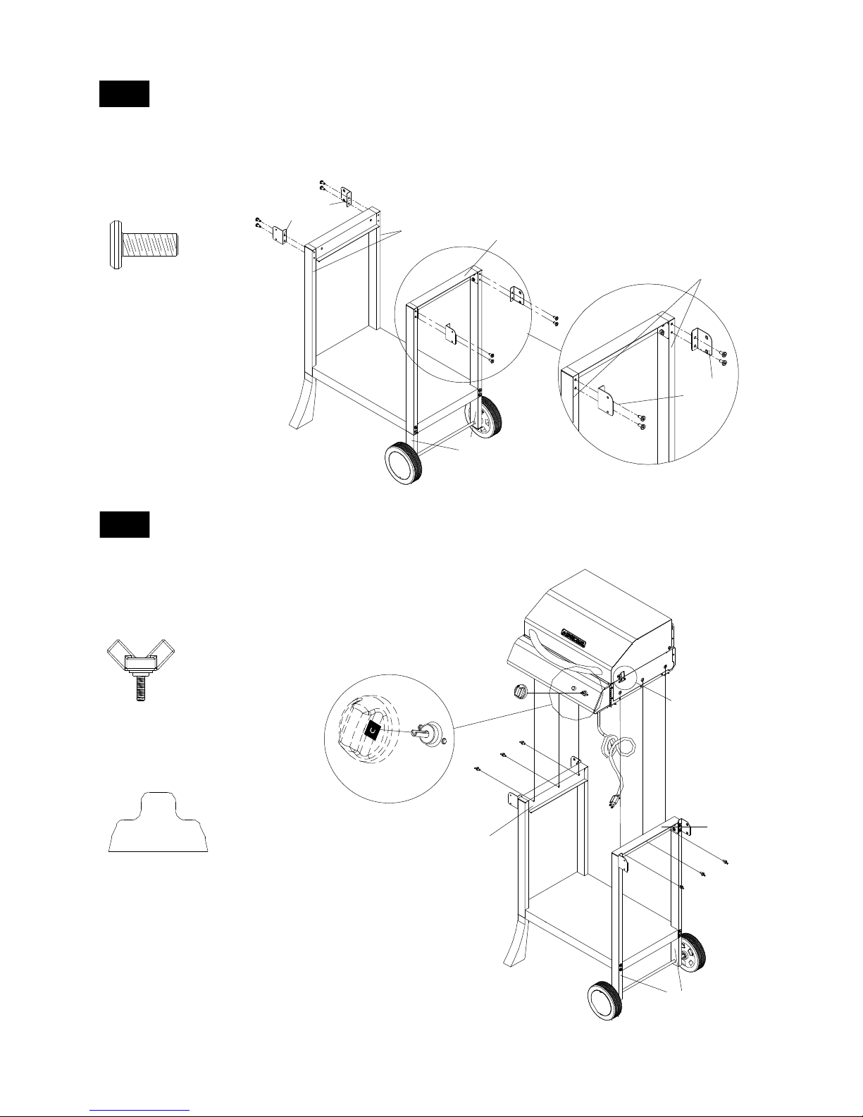
5
Install Side Shelf Brackets (Fig. 5)
Wing Bolt
1/4 in. x 5/8 in.
Qty. 6
Part # S233G04104
Control Knob for
Electric Burner
Qty. 1
Part # PD13010050
Scale: 1:2
Install Grill Head and Control Knob (Fig. 6)
6
Fig. 6
1.
2.
3.
1.
2.
3.
LF
Side Shelf
Brackets
Lower Left
Cart Legs
LR
Lower Right
Cart Legs
Cart Bottom
Shelf
RR
RF
Side Shelf
Brackets
Upper Left
Cart Legs
Upper Right
Cart Legs
Right Bowl
Bracket
3.
Fig. 5
Phillips Head Screw
1/4 in. x 1/2 in.
Qty. 8
Part # S112G04084
Lower Right
Cart Legs
Right Bowl
Bracket
Grill Head
Upper/Lower
Lid Latches
Cart Bottom
Shelf
Lower Left
Cart Legs
Left Bowl
Bracket
Control
Knob
Attach the Side Shelf Brackets, (RF/RR) to the Upper Right
Cart Legs.
Insert 4 Phillips Head Screws 1/4 in. x 1/2 in. and tighten
securely.
Repeat steps for Left Side Shelf Brackets to Upper Left Cart
Legs.
Place Grill Head onto Bowl Bracket.
Tighten securely using 6 W ing Bolts 1/4 in. x 5/8 in. from
underside of Left and Right Bowl Brackets.
Attach Control Knob as shown.
Page 10
10
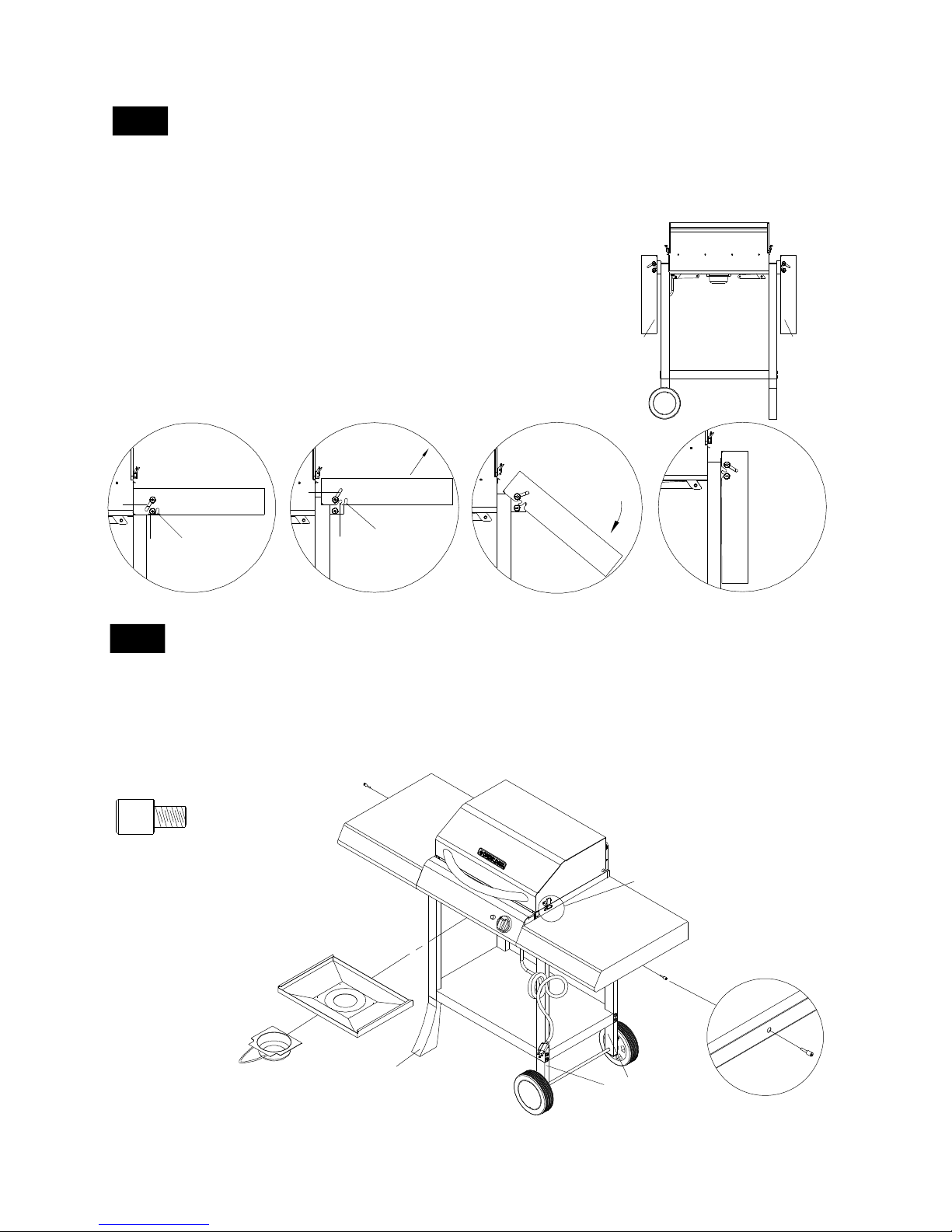
7-1
Install Side Shelf (Fig. 7)
1.
3.
2.
Pattern Head Screw
1/4 in. x 5/8 in.
Qty. 8
Part # S138G04104
4.
View from under the Right Side Shelf
Fig. 7
Right Side
Shelf
Cart Bottom
Shelf
Upper/Lower
Lid Latches
Lower Left
Cart Legs
Grill Head
Left Side
Shelf
Lower Right
Cart Legs
Hole inside the internal
upper panel frame
A
B
C
Fig. A
Fig. B
Fig. C
"L" Screwdriver
Qty. 1
Part # P05515020B
Scale: 1:2
Attach two Pattern Head Screws 1/4 in. x 5/8 in. to the lower holes
of the Right Side Shelf Brackets and tighten securely. (See Fig. A).
Align the slot B of the Right Side Shelf to the installed Pattern Head
Screws and secure the side shelf into position.
From the underside of the Side Shelf, insert one Pattern Head Screw
1/4 in. x 5/8 in. into the front Side Shelf Bracket, (see Fig. B). Then
tighten securely using a "L" Screwdriver provided. (See Fig. C).
From the underside of the Side Shelf, insert one Pattern Head Screw
1/4 in. x 5/8 in. into the rear Side Shelf Bracket and tighten securely.
Repeat for Left Side Shelf.
Page 11
11
Grease Tr ay Brac ket
8
Special Flat Head Screw
1/4 in. x 7/16 in.
Qty. 2
Part # S193G04074
Install Grease Tray and Grease Receptacle (Fig. 9)
Fig. 9
1.
4.
3.
2.
Grease Tray
Grease
Receptacle
Grill Head
Lower Left
Cart Legs
Right Side
Shelf
Left Side
Shelf
Cart Bottom
Shelf
Lower Right
Cart Legs
Upper/Lower
Lid Latches
7-2
Fold-Away Side Shelf Option (Fig. 8)
1.
3.
2.
4.
For illustration purposes - Rear View of the Left Side Shelf
Fig. 8
Left Side
Shelf
Right Side
Shelf
1.
A
B
C
2.
LIFT SIDE SHELF
A
C
B
3.
SWING
SIDE
SHELF
DOWN
4.
SLIDE
SIDE
SHELF
ALONG
THE
SLOT
With both hands grab both sides of Left Side Shelf and lift to
dislodge it from the fixed position B slots.
Pull Left Side Shelf away from the grill head and release for
Fold Away option.
Then allow the Side Shelf to slide down along the slot C
until it comes to a stop.
Repeat for Right Side Shelf.
Slide the Grease Tray side tabs over Grease Tray Bracket side
rails underneath the Grill Bowl.
Secure Special Flat Head Screw 1/4 in. x 7/16 in. to
Grease Tray Bracket (Fig. 9)
The Grease Tray is required to be present and centered for
your safety.
Slide the Grease Receptacle over Grease Tray (attached
to underside of Grease Tray) until it rests in place.
Page 12
12
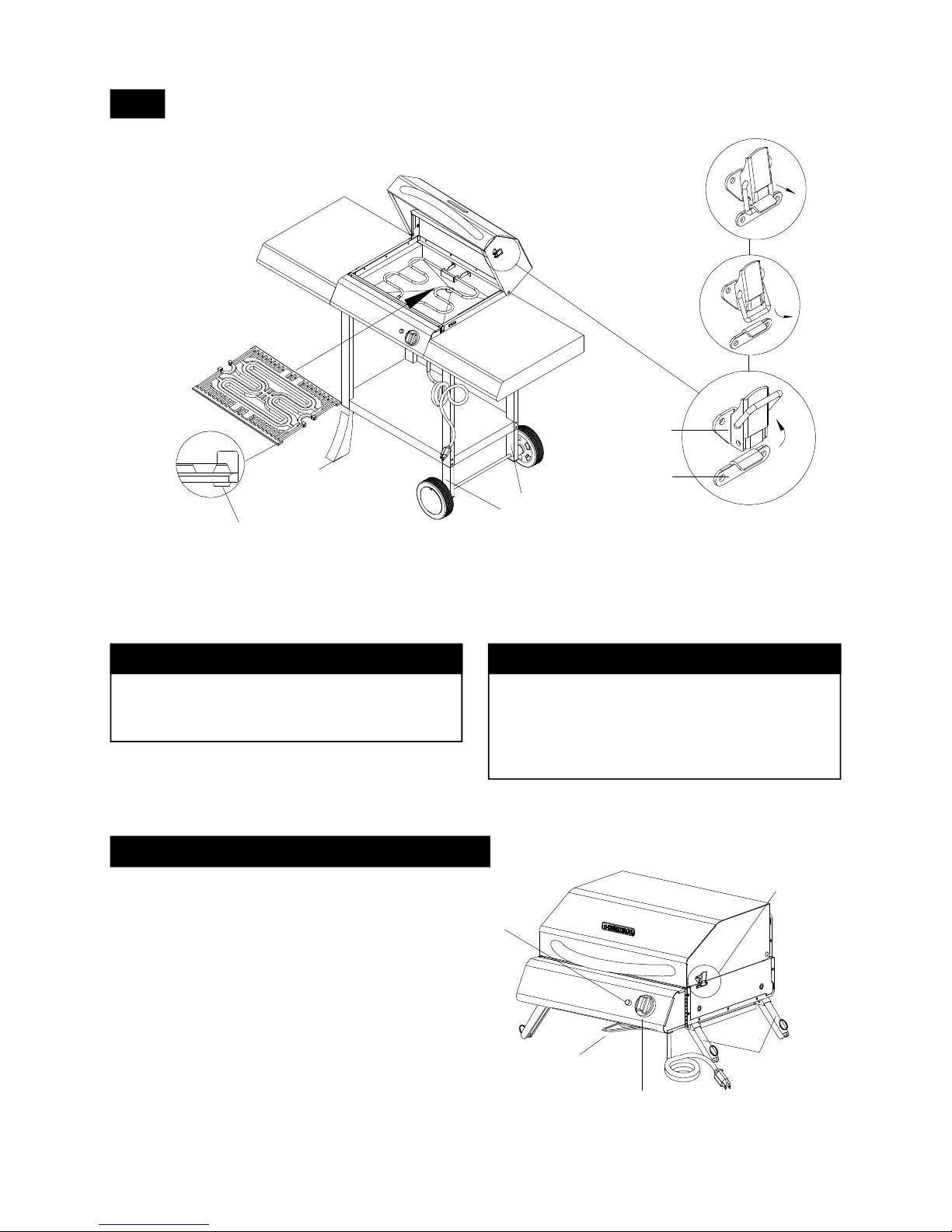
Unplug the electrical cord.
Remove Cooking Grid from inside Grill
Bowl and Grease Receptacle before
detaching the Grill Head.
With the help of an assistant, unscrew
the 6 Wing Bolts from the underside of
the Right Side Shelf and Left Side Shelf.
CAUTION: Grill Head may become
unstable when removing the Wing Bolts.
Lift and remove the Grill Head from
Bowl Bracket.
Open the foldable legs from under the
Grill Head, then reinstall the Grease
Receptacle.
1.
4.
3.
2.
Fig. 11
5.
Grill Head Lid Latches
Upper &
Lower
Electric cord
Foldable Legs
Grease
Receptacle
Foldable
Leg
Control
Knob
Temperatur e
Light
Option: Portable Grill Use (Fig. 11)
9
Install Cooking Grid (Fig. 10)
1.
Cooking Grid
Left Side
Shelf
Right Side
Shelf
Lower Left
Cart Legs
Upper
Lid Latch
Lower
Lid Latch
1.
3.
2.
Fig. 10
Cart Bottom
Shelf
Lower Right
Cart Legs
Direction: Cooking Grid
Foot Fac ing down
Final Grill Assembly Step
When you have finished assembling your
grill be sure that all screws are tightened
for safe operation of your grill.
IMPORTANT
Remove the Grease Receptacle BEFORE detaching
the Grill Head for portable or table-top use.
Reinstall the Grease Receptacle once the Grill Head
is firmly in position (with legs opened and placed on a
flat surface).
Release the latch on either side of the Lid and open the
Lid to place the Cooking Grid in the Grill Bowl ledge.
Page 13
13
USE AND CARE INSTRUCTIONS
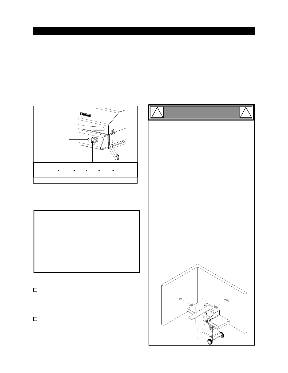
Turning Grill On
2ft.
2ft.
Failure to comply with these instructions could
result in a fire or explosion that could cause
serious bodily injury, death or property damage.
If a grill fire occurs, turn control knob to OFF,
unplug grill from outlet and allow fire to burn
out. Do not use water to put out a fire in this or
any other electrical appliance.
Never line the bottom of the grill housing with
charcoal, aluminum foil, sand or any substance
that will restrict the flow of grease into the
Grease Receptacle.
Before each use of your grill: Pull out the Grease
Receptacle and remove all grease and food debris to
prevent grease fire hazard.
Use your grill at least 2 feet away from any
wall or surface. Use your grill at least 2 feet
away from combustible objects that can melt or
catch fire (such as vinyl or wood siding, fences
and overhangs) or sources of ignition including
pilot lights on water heaters and live electrical
appliances.
Never use your grill in a garage, porch, shed,
breezeway or any other enclosed area.
In windy conditions, always position the front of
grill to face oncoming wind to reduce smoke and
heat blowing in your face and prevent potential
haza rds to self and grill.
WIND
DIRECT ION
The suggested heat settings and cooking times
shown on the Manual to Grilling on page 16 are
approximate. Unlike the controlled environment
inside your kitchen, variables including outside
temperatures, direction and conditions of wind, as
well as grill locationwill affect your grill's heat
distribution. Because these conditions vary, and
no two back- yards are alike, we offer this guide as
a convenience. We recommend youmonitor your
grill closely and rotate foods as needed to prevent
over cooking and ensure the most delicious
resultsevery time.
An ImportantNote About Cooking Temperatures
1.
2.
3.
4.
5.
6.
Make sure the Control Knob is set to OFF.
Disconnect other appliances from the circuit before
using your grill.
Plug grill into properly grounded GFCI, 120VAC, 15A
outlet.
Turn Control Knob to the Right on the highest setting
and close Lid.
Allow grill to preheat 15-20 minutes then adjust to your
desired cooking temperature.
Temperature Light will turn off when the grill reaches
desired temperature. The grill and Temperature Light
will cycle on and off as needed to maintain the desired
temperature.
IMPORTANT: AUTO SWITCH OFF MODE
The internal Electric Timer Module will automatically switch the heating element to power OFF
when it is in continous operation more than 2
1/2 hours.
To reset the internal timer, turn the Control Knob
to OFF and unplug the cord from power outlet,
then plug the cord back in and turn Control
Knob to desired cooking temperature.
Turning Grill Off
1.
2.
Turn Control Knob to OFF.
Unplug electrical cord from outlet.
Temperature
Light
Flare-Ups
The fats and juices dripping from grilled food can
cause flare-ups. Since flare-ups impart a favorably,
distinctive taste and color to grilled foods, they should
be accepted up to a point.
Always preheat the grill using the highest setting for
15-20 minutes with the Lid closed. Preheating the grill
increases the grill surface temperature and reduces
the actual cooking time.
Preheating
WARNING
! !
Control Knob Setting
OFF
LOW
HI MAXMED
Page 14

1414
If the grillcooks too slowly:
If the Temperature Light is not on:
If you have excessive flare-ups when cooking:
Thefatsand juices dripping from grilled foodcan
cause flare-ups. Since f lare-ups impart afavorable, distinctive taste andcolor to grilled foods
they should be accepted up to a point. To
minimize flare-upstry thefollowing:
Use a cooking pan to grill foods that produce a
lot of grease.
Trim excessfat from meat beforegrilling.
Use a lower temperature setting.
Grease and food build up inside your grill and
GreaseReceptacle.
Be sure your grill is turned OFF, unpluggedand
nothot. Then followthe Cleaning and Maintenance steps found in this manual to clean the
cooking grid, grease receptacle and inside of
bowl and lid.
1.
2.
a.
b.
c.
a.
Circuitbreaker continues to trip:
Caused by a power surge.
Make sure the Control Knob is set to OFF before
pluggingOR unpluggingyourgrill.
Circuit may be overloaded with appliances.
Disconnect other appliances from the circuit
when using your grill.
Electrical connections may be damp or wet.
Always keep cord dry and off the ground.
Never put the cord or heating element in water
or any liquid.
Never operate your electric grill when it is
raining.
Depending on the humidity in your area, it may
take a day or more for electrical circuits to
thoroughly dry before the breaker will reset.
This is not a defect of the product.
Electrical Cord may be damaged. Never
operate your grill if the cord or plug appears
damaged.
Call 1-877-550-8041for Grand Hall certified
replacement parts.
1.
2.
3.
4.
a.
a.
c.
b.
a.
d.
a.
GRILL INFORMATION CENTER
Call 8am to 4:30pm CST 1-877-550-8041 Monday through Friday
Be sure there is power to the grill.
Control Knob may be in OFF position.
Temperature Light will turn off when the grill reaches
desired temperature. The grill andTemperature Light
will cycle on and off as needed to maintain the exact
temperature.
Temperature Light or Heating Element may need
replacing.
Call 1-877-550-8041for Grand Hall certified replacement parts.
1.
2.
3.
4.
a.
Turn Control Knob to higher setting.
Use of an extension cord can reduce your grill
performance.
Connect grill to outlet with no extension cord.
If you must use an extension cord use only outdoor
extension cords marked with letters "W-A" and
with a tag stating "Suitable for Use with Outdoor
Appliances".
3.
4.
a.
b.
Always preheat the grill 15-20 minutes with the Lid
closed.
Keep grill Lid closed as much as possible during
the cooking process to minimize heat loss.
Reposition grill to reduce affect of wind.
1.
2.
a.
If the grill fails to produce any heat:
Be sure there is power to the grill. Turn the
Control Knob OFF and try the following:
Plug cord into properly grounded outlet.
GroundFault Circuit Interrupter(GFCI) may be
tripped. Reset or replace if needed.
Outlet may be faulty. Try another outlet.
Control Knob may be in OFF position.
Turn Control Knob to highest setting.
Heating Element may needreplacing.
Call 1-877-550-8041for Grand Hall certified
replacement parts.
The internal Electric Timer Module will automatically switch the heating element to power
OFF when it is in continous operation more
than 2 1/2 hours.
To reset the internal timer, turn the Control
Knob to OFF and unplug the cord from power
outlet, then plug the cord back in and turn
Control Knob to desired cooking temperature.
1.
2.
3.
a.
b.
c.
a.
a.
a.
4.
TROUBLESHOOTING
Use only 3-wire extension cords that have 3prong grounding-type plugs and 3-pole cord
connectors that accept the plug from the
appliance. Only extension cords identified by
the marking "Suitable for use with outdoor
appliances" shall be used outdoors. Use only
extension cords having an electrical rating not
less than the rating of the appliance. Do not
use damaged extension cords. Examine extension cord before using and replace if damaged.
Do not abuse extension cord and do not tug
on any cord to disconnect. Keep cord away
from heat and sharp edges.
Outdoor extension cords shall be used with
outdoor use products; such cords are surface
marked with suffix letters "W-A" and with a tag
stating "Suitable for use with outdoor appliances" ; Connection to an extension cord shall
be kept dry and off the ground; Store products
indoors when not in use, out of the reach of
children; and do not clean this product with a
water spray or the like.
1.
2.
Extension Cords:
Grounding Instructions:
This appliance shall be grounded while in use
to protect the operator from electrical shock.
The appliance is equipped with a 3-conductor
cord and a 3-prong grounding-type plug to fit
the proper grounding-type receptacle. Plug into
a GFCI-protected outdoor receptacle, where
available.
Page 15

Proper care and maintenance will keep your grill in top
operating condition and prolong its life. Follow these
cleaning proc ed ures o n a timely basis and your grill will
stay clean and operate with minimu m effort.
CAUTION: Be sure your grill is OFF and cool before cleaning.
Cleaning The Cooking Grid
Before in itial use, and periodically, wash your
Cooking Grid in a mild soap and warm water
solution. You can use a wash cloth or vegetable
brush to clean your Cooking Grid.
Cleaning The Grease Receptacle
To reduce the chance of fire, the Grease Receptacle should be visually inspected before each grill
use. Remove any grease and wash Grease
Receptacle with a mild soap and warm water
solution.
Cleaning the Inside of the Grill Lid
Grease can build up on the inside of the Grill Lid
and could drip onto deck or patio when the lid is
opened. Visually inspect the inside of the Grill Lid
before each grill use. Remove any grease and
wash with a mild soap and warm water solution.
Regular Cleaning of The Grill Interior
Burning-off excess food after every cookout will
keep it ready for instant use. However, at least every
3 months you must give the entire grill a thorough
cleaning to minimize your risk of grease fire and
keep the grill in top shape.
Before initial use, and periodically thereafter, we
suggest you wash your grill using a mild soap and
warm water solution. You can use a wash cloth or
sponge for this process. Do not use a stiff wire or
brass brush. These will scratch stainless steel
and chip painted surfaces (varies by model) during
the cleaning process.
Cleaning Exterior Surfaces
CLEANING AND MAINTENANCE
15
Cleaning Exterior Stainless Steel Surfaces:
Routine care and maintenance is required to preserve
the appearance and corrosion resistance of stainless
steel. The fact is stainless steel can corrode, rust and
discolor under certain conditions. Rust is caused
when regular steel particles in the atmosphere
become attached to the stainless steel surface. Steel
particles can also become attached to your grill if you
use steel wool or stiff wire brushes to clean the grill
instead of non-abrasive cloth, sponge or nylon
cleaning tools. In coastal areas rust pits can develop
on stainless surfaces that cannot be fully removed.
Bleach and other chlorine based solutions used for
household and pool cleaning can also cause corrosion to stainless steel. W eathering, extreme heat,
smoke from cooking and machine oils used in the
manufacturing process of stainless steel can cause
stainless steel to turn tan in color. Although there are
many factors which can affect the surface appearance
of stainless steel, they do not affect the integrity of the
steel or the performance of the grill.
To help main tain the finish o f stainless steel follo w
these cleaning procedures for the best results:
After every use (after your grill has cooled down), wipe
stainless surfaces with a soft, soapy cloth or sponge
then rinse with water. Be sure to remove all food
particles, sauces or marinades from stainless steel
because these can be highly acidic and damaging to
stainless surfaces.
Never use abrasive cleaners, scrubbers or stiff wire
brushes of any type on your grill.
Use a heat resistant Stainless Steel Cleaner and rub
or wipe in the direction of the stainless steel grain or
polish lines NOT against the grain.
1.
3.
2.
Online Registration and FAQ's now
available at www.grandhall.com
For personal assistance, call the Grill Information Center, 8am to 4.30pm CST, Monday through Friday at:
1-877-550-8041
Page 16

16
Guide to Grilling
Grilling Steak
Preheat the grill using the highest setting for 15-20
minutes with the Lid closed. Open Lid and place the
meat on the Cooking Grid. Cook the meat on both
sides until seared. Maintain high heat and cook until
done. Grilling times will vary according to meat
thickness.
Grilling Hamburgers
Preheat the grill using the highest setting for 15-20
minutes with the Lid closed. Open Lid and place the
meat on the Cooking Grid. Cook the meat on both
sides until seared. Maintain heat and cook until
done. Grilling times will vary according to meat
thickness.
GrillingPoultry
Preheat the grill using the highest setting for 15-20
minutes with the Lid closed. Open Lid and place the
poultry on the Cooking Grid. Cook the poultry on both
sides until seared. Reduce heat and cook until done.
Grilling times will vary according to poultry thickness.
Poultry skin is fatty so you should expect some flareups. To minimize flare-ups, try grilling poultry in a
cooking pan.
Grilling Pork
Preheat the grill using the highest setting for 15-20
minutes with the Lid closed. Open Lid and place the
meat on the Cooking Grid. Cook the meat on both
sides until seared. Reduce heat and cook until done.
Grilling times will vary according to meat thickness.
Grilling Fish
Preheat the grill using the highest setting for 15-20
minutes with the Lid closed. Open Lid and place fish
(skin down) on the Cooking Grid. Cook the poultryon
both sides until seared. Reduce heat and use cooking time as a guide or until fish is opaque but still
moist.
Vegetables and Fruit
Preheat the grill using the highest setting for 15-20
minutes with the Lid closed. Open Lid and place food
on the Cooking Grid then reduce heat. Vegetables
and fruit that work best on the grill are relatively soft
and require a short cooking time: mushrooms, zucchini, tomatoes and skewered fruit such as apricots,
peaches, pineapple, strawberries and kiwis.
CutofMeat
T-bone steak
Sirloin steak
Filet Mignon
Porterhouse steak
New York strip steak
Hamburgers
Chicken breast
(boneless, skinless)
Chicken wing s
Drumsticks
Chops
Loins
Cutlets
Whole fish
Whole fish fillets
Approx.CookingTimes
Rare: 7-10 minutes
Medium: 12-15 minutes
Well done: 18-20 minutes
Medium: 8 minutes
Medium Well: 8-10 minutes
Well done: 12 minutes
10 minutes per side
20 minutes
3 - 5 minutes or until
fish is opaque
For very firm vegetables—particularly potatoes and
yams, we recommend that you partially boil until
almost cooked, before placing them on the grill.
Cooking times will be comparable to normal pan
frying or grilling.
All cooking times are after grill has been properly pre-heated
Page 17

Grand Hall Enterprise Co., Ltd. will warrant to the ORIGINAL PURCHASER of this grill that it will be free of
defects in material and workmanship for set periods below from the date of purchase when used under normal
outdoor use and correct assembly:
Full Warranty on Grill – 1 year (except for paint loss and rusting)
Stainless Steel Parts – 3 years, no rust through
Cooking Grid – 2 years, no rust through
Grand Hall will require reasonable proof of your date of purchase. Therefore, you should send in the owner
registration card or register online at
www.grandhall.com. Save your receipt in case it is required as proof of
purchase.
This Limited warranty is limited to repair or replacement of parts, at Grand Hall’s option that prov ed to be
defective under normal use and service.
Grand Hall may require the return of defective parts for examination before issuing replacement parts or
repairs. If you are required to return defective parts, transportation charges must be prepaid.
Upon examination and to Grand Hall’s satisfaction, if the original part is proven defective Grand Hall may
approve your claim and elect to replace such parts without charge. You are responsible for shipping charges of
such replacement parts.
This warranty does not cover scratches, dents, corrosion or discoloration caused by weather, heat, abrasive and
chemical cleaners, pool or spa chemicals or any tools used in the assembly or installation of this unit. This
warranty does not cover paint loss, surface rust or stainless steel discoloration which is considered normal wear.
This warranty doesnot cover the cost of any inconvenience, personal injury or property damage due to improper
use or product failure.
This Warranty does not cover any failures or operating difficulties due to accident, abuse, misuse, alteration,
misapplication, vandalism, improper installation, maintenance or service, damages caused by flashback fires or
grease fires, as set out in this Operator’s Manual.
Deterioration or damage due to severe weather conditions such as hail, hurricane, earthquakes, tsunami, tornadoes, Acts of God or terrorism, discoloration due to exposure to chemicals either directly or in the atmosphere, is
not covered by this Limited Warranty.
No returns will be accepted without prior authorization from Grand Hall. Authorization for return may be
obtained by calling 1-877-550-8041
8 am – 4:30 pm CST, Monday through Friday.
WarrantyRestrictions
•
Limited Warranty
Manufacturer:
Grand Hall Enterprise Co., Ltd.
9th Fl., No.298, Rueiguang Rd., Neihu,
Taipei, Taiwan(114)
•
•
This warranty is void if grill is used for commercial or rental purposes.
This grill is safety certified for use only in the country where purchased. Modification
for use in any other location is a safety hazard and will void the warranty.
This warranty gives you specific legal rights, and you may also have other rights
which vary from state to state.
Page 18

Manual # P80173002H Fecha:2008/03/25
Parrilla eléctrica de doble función
246563
Modelo
LE1808CA
Impreso en China
Esta parrilla de doble función puede ser usada como modelo portátil o empotrada en la carreta como se muestra.
NOTA AL ENSAMBLADOR / INSTALADOR:
Deje este manual con el consumidor.
NOTAAL CONSUMIDOR:
Retenga este manual para consultas futuras.
INSCRIBA SU # DE SERIE__________________
(Vea la etiquete en su parrilla)
IMPORTANTE:
Fallo en cumplir con estas instrucciones puede
resultar en un incendio, o descarga eléctrica que
pudiese causar serias lesiones al cuerpo odaños
a la propiedad.
SÓLO PARA USO AL AIRE LIBRE. NO LA
USE DENTRO DE LA CASA O PARA USO
COMERCIAL.
Ya sea esta parrilla ensamblada por usted u otra
persona, usted debe leer este manual por
enteroantesdeusarsuparrillaparaasegurarse
que la parrilla esté bien ensamblada, instalada y
mantenida.
La superficie de suparrilla estarámuy caliente.
Siempre use guantes retardantes de calor para
barbacoa cuando cocina en su parrilla. Nunca se
incline sobre las superficies de cocinar mientras
está usandola parrilla. No toquela superficie de
cocinar, tapa, armazón uotras partes mientras la
parrillaestáenoperación, espérese hasta que se
enfríe por completo.
Use su parrilla a NO menos de 2 pies de
distanciade cualquierpared o superficie. NO
menos de2piesde cualquier objeto combustible,
derretible o inflamable (como v inilo orevestimento,
cercas y techos) u orígenes de inicio incluyendo
llamas de piloto de calentadores de agua u otros
aparatos eléctricos.
ADVERTENCIA
! !
MANUAL DEL OPERADOR
YUDA GRATUITA
DE LOS EXPERTOS DEL GRILL
No lo devuelva a la tienda. En Grand Hall
somos expertos en este producto y estamos
formadospara ayudarle con:
visite
www.grandhall.com o llame al :
1-877-550-8041
Lunes- Viernes 8:00 am-4:30 pm CST
Preguntas de montaje
Funcionamiento del Grill
Sustitución de partes dañadas o que faltan
Page 19
2
Tabla de contenido
Advertencias principales de seguridad...... 1-3
Instrucciones para antes del ensamblaje ...3
Listas de partes y diagramas................. 4-6
Instrucciones para el ensamblaje............7-12
Uso y cuidado ............................................ 13
Como prevenir problemas............................ 14
Limpieza y mantenimiento .......................... 15
Guía para asar ............................................ 16
Términos de la garantía ....
Portada de atrás
PROTECCIÓN IMPORTANTE
Al usar esta parrilla o cualquier otro aparato
eléctrico, precauciones básicas deben seguirse
Leer todas las instrucciones.
No tocar superficies calientes. Use las
manijasy perillas.
Para protegerse contra choque eléctrico. No
moje la cuerda, enchufes, o la parrilla con
ningún líquido.
Debe haber supervisión cerca de niños.
Desconecte del enchufe antes de limpiar.
Permita que la parrilla se enfríe antes de
remover o colocar partes.
No opere ningún aparato con una cuerda
dañada o enchufe o después que el aparato
malfunciona, o que esté dañado en cualquier
forma. Devuelva el aparato a la facilidad
autorizada de servicio más cercana, para un
examen, reparaciones o ajustes.
No se recomienda el uso de accesorios que
no sean recomendados por el fabricante, ya
que pueden causar lesiones.
No permita que la cuerda cuelgue del borde
de la mesa, área de trabajo, o que toque las
supeprficies calientes.
No coloque su parrilla cerca de gas caliente,
o de un fogón eléctrico caliente o un horno
caliente.
Use extremado cuidado al mover utensilios
que contienen grasa caliente u otros líquidos
calientes.
Fije primero, el enchufe del aparato
electrodoméstico en el receptáculo del poder
eléctrico de la curda de extensión, luego
enchufe la cuerda en el tomacorriente de la
pared.
Para desconectar, ponga los controles en
OFF, y luego desenchúfe del tomacorriente.
Este aparato no se debe usar en ninguna
otra manera que la intentada por el
fabricante.
En esta parrilla no se deben usar combustibles como gas, carbón o leña.
•
•
•
•
•
•
•
•
•
•
•
•
•
•
Enchúfela a un tomacorriente propiamente
puesto a tierra.
Se le ha proporcionado una cuerda eléctrica
corta y desprendible para reducir la
posibilidad de que se enrede en algo o que
se tropieze con una cuerda más larga.
1) Si piensa usar una cuerda de extensión, la
clasificación de esta debe ser lo mismo o
más alta que la calsificación del aparato
eléctrico.
2) La cuerda debe ser arreglada para que no
sobresalga del borde del área de trabajo
donde niños pueden jalarla o tropezarse
contra la cuerda accidentalmente.
3) Este aparato debe ser puesto a tierra, la
cuerda de extensión debe también estar
puesta a tierra. Use tipo -3 de alambre eléctrico.
Cuerdas de extensión para uso al aire libre
deben ser usadas con productos para uso al
aire libre y estos están marcados con las
letras "W-A" y con una etiqueta que indica
"Apropiada para ser usada en aparatos de
uso al aire libre".
La conexión a la cuerda debe mantenerse
seca y fuera del piso.
Guarde los productos adentro cuando no los
usa – fuera del alcance de los niños.
No rocíe este producto o use nada similar.
GUARDE
ESTAS INSTRUCCIONES
•
•
•
•
! !
Fallo en leer y seguir las instrucciones
de Uso y Cuidado puede resultar en un
incendio o descarga eléctrica lo cual
puede causar serias lesiones al cuerpo,
muerte o daños a la propiedad.
ADVERTENCIA
IMPORTANTE
Remueva el receptáculo para la grasa ANTES de
separar el cabezal de la parrilla para e l uso p ortátil o
colocarlo en una superficie plana.
Reinstale el recipiente de grasa cuando el cabezal de
la par rilla esté firmemente en p osición (con la p atas
abiertas y puesto sobre una superficie plana).
•
Page 20

3
!
PELIGRO
!
USE AND SAFETY
El uso de una cuerda de extensión no se recomienda
para esta parrilla.
Esta parrilla esta clasificad a para 1 ,700 vatios y
120VAC.
Si usted debe usar una extensión, para su
seguridad: use solamente extensiones especificadas
para uso al aire libre marcadas con el sufijo "W-A"
y con una etiqueta declarando "Apropiado para
aparatos de uso al aire libre".
No u se en su parrilla cuerdas eléctricas de extensión
calibradas entre 16 o 18. Pueden causar daños all
cableado de su residencia y/o causar un incendio.
No use carbón o ningún tipo de combustible
dentro de esta parrilla. El uso de carbón o
combustibles d añará su parrilla y puede resultar
en un fuego o explosión que podría causar
lesiones serias al cuerpo, muerte o daños a la
propiedad.
Los componentes metálicos, como el eje de la
válvula del termostato usados en esta barbacoa
eléctrica, contienen plomo, conocido por el Estado
de California como causante de cáncer, Defectos
de nacimiento, u otros daños reproductivos.
!
WARNING
!
•
•
•
•
•
Herramientas que se necesitan,
Guantes de trabajo, tipo industrial
Por su seguridad, consiga la ayuda de otra per
sona cuando monte esta barbacoa a gas.
Destornillador con cabeza Phillips #2 y # 3.
Abra la tapa del cartón de envío y saque la caja de
partes y materiales de empaque. Coloque una hoja
grande de cartón en el piso y use el espacio como
área de trab ajo para proteger la superficie del piso y
partes de la parrilla de rayones.
Puede cortar las esquinas del cartón con una
cuchilla para abrir el panel frontal. Esto le permitirá
alzar la tapa del c abezal de la parrilla y sac ar los
componentes empacados adentro. Use el pedazo
de cartón frontal como área para trabajar e impedir
raspados de las partes y proteger el piso.
Use los diagramas de partes y ferretería para
asegurarse que todas las partes están incluídas y
que no tengan daños.
Mientras que es posible que una persona sola pueda
ensamblar esta parrilla, obtenga la ayuda de otra persona cuando necesite manejar las partes grandes y
más pesadas.
No ensamble u opere la parrilla si ap arenta tener
daños. Si hay piezas dañadas o faltantes cuando
usted desemp aca la caja de envío o usted tiene
preguntas durante el proceso del ensamblalje,
llame:
•
•
PRE-ENSAMBLAJE
Lea y ejecute las siguientes instrucciones de preensamblaje:
Centro de Información de Parrillas 1-877-550-8041
8am a 4:30pm CST, de lunes a viernes
•
•
Desde 1971 El Código Nacional de Electricidad
(NEC) ha requerido el uso de dispositivos para
circuitos conectados al aire libre.
Si su casa fue construida antes de 1971, haga
que un electricista le diga si existe un
Interruptor Accionado por Pérdida de conexión.
No use este aparato si su circuito no contiene
un GFCI de protección.
No enchufe esta parrilla a un circuito dentro
de la casa.
•
•
•
•
Requerido: Un Interruptor Accionado por
Pérdida de
Conexión a Tierra
Guarde estas instrucciones para
futura referencia
Debe conectar la cuerda sólo a un tomacorriente
GFCI (Interruptor Accionado por Pérdida de
Conección a Tierra) y correctamente puesto a
tierra.
Nunca opere la parrilla cuando está lloviendo.
Mantenga la cuerda eléctrica seca y fuera de
contacto con la tierra.
Nunca coloque la cuerda eléctrica o el elemento
en agua o cualquier líquido.
Para prevenir que se moje o que se caiga al
agua su parrilla, No la ubique a menos de 10
pies de una alberca, pozo, balneario, llave de
agua, o cualquier depósito de agua.
Asegúrese que la perilla de control esté en
OFF antes de enchufar O
desenchufar.
Desenchufe su parrilla cuando no está en uso
o antes de moverla de sitio.
No jale la cuerda para desenchufar su parrilla.
Mantenga la cuerda fuera de superficies
calientes.
Nunca opere su parrilla si la cuerda se ve
dañada.
Nunca remueva la puesta a tierra o use un
adaptador con sólo dos puntas.
Desenchufe la parrilla si va a usar agua o
cualquier líquido o para limpiarla.
UNA DESCARGA ELÉCTRICA PUEDE CAUSAR
LA MUERTE O RESULTAR EN LESIONES
GRAVES.
Proposición de California 65
•
•
•
•
•
•
•
•
•
•
•
•
Page 21

Perilla de control del
fogón eléctrico
Cantidad 1
Parte # PD13010050
Escala 1:2
Paquete de ferretería para el Modelo LE1808CA
Perno mariposa
1/4 in. x 5/8 in.
Cantidad 6
Parte # S233G04104
Arandela 7/16 in.
Cantidad 2
Parte # S411G07012
Tornillo de cabezal estriado
1/4 in. x 5/8 in.
Cantidad 8
Parte # S138G04104
Tornillo con cabeza Phillips
1/4 in. x 1/2 in.
Cantidad 16
Parte # S112G04084
Tornillo con cabeza Phillips
1/4 in. x 2 in.
Cantidad 8
Parte # S112G04324
Pasador hendido Cotter
Cantidad 2
Parte # P05501106B
Paquete de ferretería - Lista de partes para el Modelo LE1808CA
4
Tornillo especial con
cabeza plana
1/4 in. x 7/16 in.
Cantidad 2
Parte # S193G04074
AVIS O : Si cualquiera de los alambre proporcionados con el aparato necesitan ser reemplazados, debe ser
reemplazado por el tipo especificado como se describe arriba o su equivalente.
Diagrama de especificaciones y cableado
Clasificación de Poder AC: 120 VAC / 60 Hz, 1,700 Vatios
Alcance de temperatura entre: 120°F ~570°F
•
•
AC120V/60Hz
Verde/AWG14/105°C
armazón
Blanco/AWG14/105°C
Negro/AW G14/105°C
Blanco/AWG14/105°C
Blanco/AWG18/105°C
Negro/AW G18/105°C
Blanco/AWG14/200°C
Negro/AW G14/200°C
Elemento de calor
120VAC/1,700Vatios
Indicador
120VAC
Módulo de control
de tiempo
Termostato
120°F~570°F
PART # DESCRIPCIÓN DE LAS PARTES UNIDADES USO DE LAS PARTES
P06027002A Paquete de ferretería 1 Para uso en el ensam blaje del Modelo LE1808CA
P05501106B
Pasador hendido Cotter 2
S411G07012
Arandela 7/16 in. 2
S112G04324 Tornillo con cabeza Phillips 1/4 in. x 2 in. 8
Fija el soporte de la repisa inferior de la carreta a través de las
patas de la carreta
S112G04084 Tornillo con cabeza Phillips 1/4 in. x1/2 in. 8 Fija el soporte del tazón a las patas de arriba de la carreta
S112G04084 Tornillo con cabeza Phillips 1/4 in.x 1/2 in. 8 Fija el soporte de la repisa lateral a las patas de la carreta
S233G04104 Perno mariposa 1/4 in. x 5/8 in. 6 Fija el cabezal de la parrilla al soporte del tazón
PD13010050
Perilla de control del fogón eléctrico 1 Fija el panel de control
S138G04104 Tornillo de cabezal estriado 1/4 in. x 5/8 in. 8
P05515020B
Destornillador tipo "L" 1
S193G04074
Tornillo especial con cabeza plana
1/4 in. x 7/16 in.
2 Fija el s oporte de la bandeja para la grasa
Fija el eje y las ruedas a las patas de arriba de la carreta
Fija las repisas laterales al soporte de la repisa lateral
Destornillador tipo "L"
Cantidad 1
Parte # P05515020B
Escala 1:2
Page 22

Diagrama de partes para el Modelo LE1808CA
5
1
5
3
4
10
13
9
8
11
7
21
20
17
18
14
15
16
6
27
28
34
33
31
30
32
24
23
25
26
18
17
24
23
29
19
2
22
12
21
22
35
Page 23

Lista de partes para el Modelo LE1808CA
Código Descripción Parte # Unidades
1 Tapa PD01010015 1
2 Moldura de la tapa PD01020012 1
3 Manija de la tapa PD02010015 1
4 Placa c on el nombre P00414041C 1
5 Cierre de la tapa, superior PD03010011 2
6 Cierre de la tapa, inferior PD03020011 2
7 Exterior del tazón PD04010015 1
8 Interior del tazón PD04020012 1
9 Fogón eléc trico PD05010010 1
10 Cuadrículo para cocinar PD07010013 1
11 Soporte del termost ato PD08010025 1
12 Protector del termostato PD08010042 1
13 Soporte del fogón PD16010025 1
14 Protector de calor del panel de c ontrol PD08010015 1
15 Ensamble del panel de control PD09010015 1
16 Perilla de c ontrol PD13010050 1
17 Pata plegable PD17030015 4
18 Agarre de la pata PD17040015 4
19 Bandeja para drenaje de grasa PD14010012 1
20 Receptác ulo para la grasa PD14020012 1
21 Soporte de la bandeja para la grasa PD16040015 2
22 Soporte del tazón PD16010042 2
23
Soporte de la repisa lateral, frontal izquierda/trasera
derecha
PD16030032 2
24
Soporte de la repisa lateral, frontal derecha/trasera
izquierda
PD16030042 2
25 Repisa lateral, izquierdo PD19010022 1
26 Repisa lateral, derecho PD19020022 1
27 Pata de la carreta, superior PD17010032 4
28 Repisa Inferior de la carreta PD20010012 1
29 Pata de la carreta, inferior izquierda PD17020012 2
30 Pata de la carreta, inferior derecha PD17020032 2
31 Tapa del extremo de la pata PD21010010 2
32 Eje de la rueda PD18010015 1
33 Rueda P05101001A 2
34 Tapa de la rueda P05116001B 2
35 Material protector de Patas de la carreta, inferior izquierda PD17020056 2
Paquete de ferretería P06027002A 1
Manual del Operador P80173002H 1
6
Importante: Sólo use para reemplazo las partes certificadas de Grand Hall. El uso de cualquier parte que
no sea autorizada puede ser peligroso y le anulará la garantía del producto. Mantenga el Manual de
Operación en un lugar conveniente para su referencia y lista de partes.
Para ordernar partes de reemplazo certificados de Grand Hall, llame al 1-877-550-8041
Para obtener las partes correctas de reemplazo para su parrilla eléctrica, favor refiérase al número de
parte en esta lista. La siguiente información es para asegurarse que recibirá las partes correctas:
1. Modelo Número de serie (Vea la etiqu eta UL en la parrilla)
2. Número de parte
3. Descripción de parte
4. Cantidad de partes requeridas
Nota: Esta parrilla puede ser ensamblada en aproximadamente 30 minutos.
Page 24

Pata
inferior
izquierda
de la
carreta
Pata superior izquierda
de la carreta
Pata
superior
derecha
de la
carreta
Pata
Inferior
derecha
de la
carreta
Que el único
agujero de cara
hacia fuera
7
Instrucciones para el ensamblaje
1
2
Pasador hendido Cotter
Cantidad 2
Parte # P05501106B
Arandela 7/16 in.
Cantidad 2
Parte # S411G07012
Instalando las patas de la carreta (Fig. 2)
Alínie los 2 hoyos en la pata inferior derecha de la carreta
con los hoyos enroscados en la parte superior de la pata
derecha de la carreta dándoles un golpecito para forzar a
que entren y queden unidas las dos partes.
Repita estos pasos en la parte superior izquierda de las
patas de la carreta y la pata inferior izquierda de la carreta.
Instalando las ruedas (Fig. 1)
Fig. 1
Fig. 2
1.
2.
3.
4.
1.
2.
Tapa de
la rueda
Eje de la
rueda
Rueda
Eje de la
rueda
Pasador
hendido
Cotter
Pata inferior
izquierda
de la carreta
Arandela
Enrrosque el eje de las ruedas a través del frente inferior
izquierdo de las patas de la carreta.
Inserte una rueda y una arandela 7/16 in. al lado izquierdo
del eje de la rueda y asegúrela con el pasador hendido
Cotter como se muestra.
Déle un golpecito forzando la tapa de la rueda para que
entre en su lugar.
Repita estos pasos para colocar las ruedas traseras
derechas en los ejes.
Page 25

Soporte izquierdo
del tazón
Soporte
derecho
del tazón
Pata
superior
izquierda
de la
carreta
Pata Inferior
derecha de
la carreta
Pata inferior
izquierda
de la
carreta
Repisa Inferior
de la carreta
Soporte
derecho
del tazón
Que la placa plana de
car a hacia adentro
Repisa Inferior
de la carreta
Pata
inferior
izquierda
de la
carreta
Pata
superior
izquierda
de la
carreta
Pata
superior
derecha
de la
carreta
Pata Inferior
derecha de
la carreta
8
3
4
Tornillo con cabeza Phillips
1/4 in. x 2 in.
Cantidad 8
Parte # S112G04324
Instaleando la repisa inferior de la carreta (Fig. 3)
Instale el soporte del tazón (Fig. 4)
Tornillo con cabeza Phillips
1/4 in. x 1/2 in.
Cantidad 8
Parte # S112G04084
Fig. 3
1.
2.
1.
2.
3.
Fig. 4
Que el único
agujero de cara
hacia fuera
Fije el soporte derecho del tazón entre las patas superior
derechas de la carreta.
Nota: Asegúrese que la placa plana de cara hacia
adentro.
Inserte 4 torn illos con cabeza Phillips 1/4 in. x 1/2 in. y
aprételos con seguridad.
Repita estos pasos para el soporte izquierdo del tazón
entre las patas superior izquierdas de la carreta.
Fije el repisa inferior de la carreta a través de las patas
de la carreta (como se muestra).
Nota: Asegúrese que el doble agujero en las 4 patas
de cara hacia fuera.
Inserte 2 tornillos c on cabeza Phillips 1/4 in. x 2 in. en
cada pata de la carreta y aprételos con seguridad.
Page 26

9
5
Instale los soportes de las repisas laterales (Fig. 5)
Tornillo con cabeza Phillips
1/4 in. x 1/2 in.
Cantidad 8
Parte # S112G04084
1.
2.
3.
Perno mariposa
1/4 in. x 5/8 in.
Cantidad 6
Parte # S233G04104
Perilla de control del
fogón eléctrico
Cantidad 1
Parte # PD13010050
Escala 1:2
Instalando el cabezal de la parrilla y la perilla de control (Fig. 6)
6
1.
2.
3.
IP
IF
Fig. 5
Soportes de las
repisas laterales
Pata Inferior
derecha de
la carreta
Repisa Inferior
de la carreta
Pata inferior
izquierda
de la
carreta
DP
DF
Soportes
de las
repisas
laterales
Pata superior
izquierda de
la carreta
Pata superior
derecha de
la carreta
Soporte
derecho
del tazón
Fig. 6
Soporte
izquierdo
del tazón
Soporte
derecho
del tazón
Cabezal de la
parrilla
Cierre superior
y cierre inferior
de la tapa
Pata Inferior
derecha de
la carreta
Repisa Inferior
de la carreta
Pata inferior
izquierda
de la
carreta
Perilla de
control
Coloque el cabezal de la parrilla sobre el soporte del
tazón.
Aprételo con seguridad usando 6 pernos mariposa 1/4 in.
x 5/8 in. por debajo de los soportes zquierdo y derecho
del tazón.
Fije la perilla de contro l c omo se muestra.
Fije el soporte de la repisa latral derecha, (DF/DP) a la parte
superior de la pata derecha de la carreta.
Inserte 4 Tornillos con cabeza Phillips 1/4 in. x 1/2 in. y
aprételos con seguridad.
Repita estos pasos para fijar el soporte de la repisa lateral
izquierda a la parte superior izquierda de la pata superior
izquierda de la carreta.
Page 27

10
7-1
Instalando la repisa lateral (Fig. 7)
1.
3.
2.
Repisa lateral
derecha
Repisa lateral
izquierda
Hoyo dentro del marco
del panel inter no superior
Pata Inferior derecha
de la carreta
Cabezal de
la parrilla
Repisa
Inferior
de la
carreta
Pata inferior
izquierda de
la carreta
Superior/
inferior cierre
de la tapa
Vista desde debajo del estante lateral derecho
Fig. 7
A
B
C
Fig. A
Fig. B
Fig. C
Destornillador tipo "L"
Qty. 1
Part # P05515020B
Scale: 1:2
Tornillo de cabezal estriado
1/4 in. x 5/8 in.
Cantidad 8
Parte # S138G04104
4.
Una dos torn illos de cabeza estriada de
1/4 in. x 5/8 in. a los
agujeros inferiores de los soportes de estante del lado derecho y
apriételos con firmeza. (Vea la Fig. A). Alinee la ranura B del estante
del lad o derecho en los tornillos de cabezal estriado instalad os y
coloque el estante lateral en su lugar.
Desde la parte interior del estante lateral, introduzca un tornillo de
cabezal estriado de ¼" X 5/8" en el soporte del estante lateral. (ver
Fig. B). Apriete con firmeza usando el destornillador en “L” incluido.
(ver Fig. C)
Desde la parte interior del estante lateral, introduzca un tornillo de
cabezal estriado de ¼" X 5/8" en el soporte del estante posterior y
apriételo con firmeza.
Repita estos pasos para instalar la repisa izquierda.
Page 28

11
8
Tornillo especial con
cabeza plana
1/4 in. x 7/16 in.
Cantidad 2
Parte # S193G04074
Instalando la bandeja y el receptáculo para la grasa (Fig. 9)
1.
4.
3.
2.
Fig. 9
Bandeja para
la grasa
Receptáculo
para la
grasa
Repisa lateral
izquierda
Cierres inferior/
superior de la tapa.
Cabezal de
la parrilla
Pata inferior
izquierda de
la carreta
Repisa
Inferior
de la
carreta
Pata Inferior
derecha de
la carreta
Repisa lateral
derecha
Soporte de la bandeja
para la grasa
7-2
Opción de la repisa lateral plegable (Fig. 8)
1.
4.
2.
3.
Repisa
lateral
izquierda
Repisa
lateral
derecha
Fig. 8
Para propósitos de ilust racion - Vis ta trasera de la repisa lateral izquierda
4.
DESLICE LA
REPISA
LATERAL
SIGUIENDO
LA RANAURA
OSCILE HACIA
ABAJO LA REPISA
LATERAL
Afloje los tornillos
mariposa con reborde
1.
A
B
C
ALCE LA REPISA
LATERAL
2.
A
C
B
3.
Deslice las lengüetas laterales de la bandeja por encima de los
carriles que están debajo del tazón de la parrilla.
Segura tornillo especial con cabeza plana 1/4 in. x 7 /16 in.
al soporte de la bandeja para la grasa.
Para su seguridad la bandeja para la grasa se requiere esté
presente y centrada.
Deslice el receptáculo para la grasa sobre el soporte de la
bandeja para la grasa (colocado por debajo de la bandeja
para la grasa) ajústelo hasta que quede en su lugar.
Agarre con ambas manos los dos lados de la repisa izquierda y
alce para desalojarla de su posición fija B en las ranuras. Jale
las repisas laterales para alejarlas del cabezal de la parrilla y
suéltelas para la opción plegable.
Luego permita que la repisa lateral se deslice hacia abajo
siguiendo la ranura C hasta que llegue a detenerse.
Repita los pasos para la repisa lateral derecha.
Page 29

12
1.
4.
3.
2.
Fig. 11
5.
Cierres inferior/
superior de la
tapa.
cuerda
eléct rica
Patas plegables
Patas
plegables
Opción: Uso portátil
de la parrilla (Fig. 11)
Luz indicadora
de t emperatura
Cabezal de la
parrilla
Receptáculo
para la
grasa
Perilla de
control
IMPORTANTE
Remueva el receptáculo para la grasa ANTES de
separar el cabezal de la parrilla para e l uso p ortátil o
colocarlo en una superficie plana.
Reinstale el recipiente de grasa cuando el cabezal de
la par rilla esté firmemente en p osición (con la p atas
abiertas y puesto sobre una superficie plana).
Paso final del ensamblaje
Cuando haya terminado de ensamblar su
parrilla asegúrese que todos los tornillos
estén apretados para tener una operación
segura.
9
Instalando el cuadrículo (Fig. 10)
1.
Cuadrículo
para cocinar
Repisa lateral
izquierda
Repisa lateral
derecha
Cierre superior
de la tapa
Cierre inferior
de la tapa
1.
3.
2.
Fig. 10
Pata inferior
izquierda de
la carreta
Repisa
Inferior
de la
carreta
Dirección: El pie del cuadriculo para
cocinar puesto car a hacia abajo
Desenchufe la cuerda eléctrica
Remueva el cuadrículo del tazón de la
parrilla y el receptáculo para la grasa
ANTES de remover el cabezal de la
parrilla.
Con la ayuda de un asistente, destornille
los 6 pernos mariposa ubicados por
debajo de las repisas laterales derecha
e izquierda.
CUIDADO: El cabezal de la parrilla
puede volverse inestable al destornillar
los pernos.
Levante y remueva el cabezal de la
parrilla del tazó n.
Abra las patas plegables ubicadas
debajo del cabezal de la parrilla, y
reinstale el receptáculo para la grasa.
Suelte el cierre en cualquiera de los dos lados del panel de
la tapa y abra la tapa para colocar el cuadrículo para asar en
el borde del tazón de la parrilla.
Page 30

13
INSTRUCCIONES DE USO Y CUIDADO
Encendiendo la parrilla
1.
2.
3.
4
5.
6.
Asegúrese que la perilla de control está en OFF.
Desconecte los otros aparatos eléctricos del circuito
antes de usar su parrilla.
Enchufe la parrilla en un tomacorriente propiamente
puesto a tierra GFCI, 12 0VAC,15A.
Gire la perilla de control hacia la derecha para obtener
la temperatura más alta y cierre la tapa.
Permita q ue la parrilla se caliente por 1 5-20 minutos y
ajúste la parrilla a la temperatura deseada.
La luz de la temperatura se apagará a OFF cuando la
temperatura llega a su punto deseado. La parrilla y luz
de la temperatura tendrán un ciclo de inicio y apague
como se necesite para mantener constante la
temperatura deseada.
Apagando la parrilla
1.
2.
Gire la perilla de control a OFF.
Desenchufe la cuerda del tomacorriente.
IMPORTANTE: MODO DE APAGAR
AUTOMÁTICO
El módulo eléctrico de control de tiempo interno
automáticamente cortará el poder del elemento
de calor a OFF cuando está en operación por
más de 2-1/2 horas.
Para volver a fijar el control de tiempo interno, gire
la perilla de control a OFF y desconecte la
cuerda del tomacorriente por el enchufe, luego
vuelva a enchufar la cuerda por el enchufe y gire
la perilla de control a la temperatura deseada.
Fallo en cumplir con estas instrucciones puede
resultar en un incendio o descarga eléctrica que
pueden causar serias lesiones al cuerpo, muerte
o daños a la propiedad.
Si un fuego en la parrilla ocurre, gire la perilla
de control a OFF, desenchufe la cuerda del
tomacorriente y deje que el fuego se apague
por si solo. No
use agua para apagar un fuego
en cualquier aparato eléctrico.
Nunca forre el fondo del tazón con carbón, papel
de aluminio, arena o cualquier otro ingrediente
que pueda impedir que la grasa fluya al
receptáculo para la grasa.
Antes de cada uso de la parrilla: Saque el
receptáculo para la grasa y remueva toda la grasa y
restos de comida para prevenir fuegos de grasa.
Use su parrilla a no menos de 2 pies de
distancia de una pared o supérficie. Use su
parrilla a no menos de 2 pies de distancia de
objetos combustibles que se pueden derretir o
quemar (como vinilo, revestimiento de madera, o
llamas piloto, y aparatos eléctricos encendidos.
Nunca use su parrilla en un garaj e, porche,
cobertizo, pasadizo o una área cerrada.
2 pies
2 pies
En condiciones de vientos fuertes, siempre coloque
el delantero de la parrilla cara hacia el viento para
reducir que el humo y calor le peguen a su cara y
prevenir posibles peligros hacia usted y la p arrilla.
Una nota importante sobre temperaturas:
Las posiciones de calor sugeridas y los
tiempos de cocción indicados en la Manual de
Parrilla de la página 16 son aproximados.
La parrilla no es como el ambiente controlado de su
cocina, hayvariables incluyendo la temperatura de
afuera, dirección y condición del viento, lo mismo el
sitio en que está ubicada la parrilla, todos afectan
la distribución del calor. Debido a los variables y
que no hay dos patios iguales, se les ofrece la guía
para suconveniencia. Recomendamosque supervise su parrilla y rotar la comida como sea
necesario para que no se cocine demasiado, y
asegurar los mas deliciosos resultados.
ADVERTENCIA
! !
Llamaradas
El goteo de jugos y grasas que caen de la comida que
se está asando puede causar llamaradas. Ya que las
llamaradas contribuyen a darle un buen sabor a la
comida además de su color, se deben aceptar hasta
cierto punto.
Siempre pre-caliente su parrilla poniendo la
temperatura más alta por 15-20 minutos con la tapa
cerrada. El pre-calentado aumenta las temperaturas
de la superfic ie de la parrilla y reduce el tiempo del
cocinado.
Pre-calentado
Luz indicadora
de temperatura
DIRECCIÓN
DEL VIENTO
Instalación perilla de control
OFF LOW
MED
HI
MAX
Page 31

1414
Si el interruptor se sigue desconectando, pueda
ser:
Causado por una alta tensión eléctrica.
Asegúrese que la perilla de control esté puesta
en OFF antes de enchufar O desenchufar su
parrilla.
El circuito puede estar recargado con aparatos
eléctricos.
Desconecte los otros aparatos del circuito
cuando usa su parrilla.
Las conexiones eléctricas pueden estar
húmedas o mojadas.
Siempre mantenga la cuerda seca y fuera del
piso.
Nunca sumerja la cuerda o el elemento de
calentar en agua u otro líquido.
Nunca opere su parrilla eléctrica cuando está
lloviendo.
Dependiendo de la humedad en su área,
pueden tomar un día o más en secarse por
completo los circuitos antes que el interruprtor
se fuelva a reiniciar. Este no es un defecto
del producto.
La cuerda eléctrica puede estar dañada. Nunca
opere su parrilla si la cuerdao el enchufe
parecen estar dañados.
Llame al 1-877-550-8041para obtener las
partes de reemplazo certificadas por Grand Hall
1.
2.
3.
4.
Si hay demasiadas llamaradas al cocinar:
La grasa y jugos que gotean de la carne en la
parrilla pueden causar llamaradas. Ya que las
llamaradas ayudan a impartir un sabor delicioso
y le dan un sabor distintivo y color a la barbacoa
se deben aceptar hasta cierto punto.
Para disminuir las llamaradas trate lo siguiente:
Use un utensilio para asar comidas que
producen mucha grasa.
Recorte el exeso de grasa de la carneantes de
asarla.
Use una temperatura más baja.
Grasa y comida se van acumulando dentro de su
parrilla y el receptáculo de grasa.
Asegúrese que su parrilla está en OFF,
desconectada y fría. Luego siga los pasos de
limpieza y mantenimiento que se encuentran en
este manual para la limpieza del cuadrículo para
cocinar, el receptáculo de grasa y por dentro del
tazón y la tapa.
1.
2.
a.
a.
c.
b.
a.
d.
a.
a.
b.
c.
a.
Siempre pre-calientela parrilla por 15-20minutos
con la tapa cerrada.
Mantenga la tapa cerrada lo más que pueda
durante el proceso decocinar para minimizar la
pérdida de calor.
Reposicione la parrilla para reducir el efecto del
aire.
Gire la perilla de control y fíjela en el calor más
alto.
El uso de una cuerda de extensión puede reducir
la efectividadde suparrilla.
Conecte la parrilla a untomacorriente sin usar la
cuerda de extensión.
Si usted debe usar una cuerda de extensión use
una cuerda para uso al aire libre marcada con el
sufijo: "W-A" y con etiqueta que dice: "Apropiada
para ser usada en aparatos de uso al aire libre".
Asegúrese que la parrilla tienepoder eléctrico.
La perillade control puede estar en OFF.
La luz de la temperatura se apaga cuando la
temperatura llega asu punto deseado.
La luz se apaga y enciende como necesita para
mantener la temperatura correcta.
Llame al1-877-550-8041 para obtenerlas partes
de reemplazo certificadas por Grand Hall
COMO PREVENIR PROBLEMAS
Si la parrilla falla en producir calor:
Si la parrilla cocina muy despacio:
Si la luz de la temperatura no enciende:
Asegúrese que haya poder. Gire la perilla de
control a OFF y trate lo siguiente:
Enchufe la cuerda a un tomacorriente con puesta
al suelo.
El interruptor del(GFCI) ha sido desactivado.
Vuelvalo a iniciarlo o reemplázelo si es
necesario.
El tomacorriente puede estar dañado. Use otro
tomacorriente.
La perillade control puede estar en OFF.
Gire la perilla de control a la temperatura más
alta.
El elemento de calor puede necesitar
reemplazo.
Llame al 1-877-550-8041para obtener las
partes de reemplazo certificadas por Grand Hall
El módulo eléctrico de control de tiempo
interno automaticamente cortará el el poder del
elemento de calor a OFF cuando está en
operación por más de 2-1/2 horas.
Para volver a fijar el control de tiempo inerno,
gire la perilla de control a OFF y desconecte la
cuerda del tomacorriente por el enchufe, luego
vuelva a enchufar la cuerda por el enchufe y
gire la perilla de control a la temperatura
deseada.
1.
2.
3.
1.
2.
3.
4.
a.
b.
c.
a.
a.
a.
a.
b.
a.
a.
4.
1.
2.
3.
4.
CENTRO DE INFORMACIÓN DE PARRILLAS
Llame entre 8am y 4.30pm CST 1-877-550-8041 de lunes a viernes
Page 32

15
El mantenimiento y cuidado cor rec to de su parrilla la
mantendrán en buena condición y le prolongarán la vida.
Siga estos procedimientos de limpieza con regularidad
y su parrilla se mantendrá limpia y en buenas condiciones
con un esfuerzo mínimo.
CUIDADO: Asegúrese que su parrilla está en OFF y fría antes
de lim piarla.
LIMPIEZA Y MANTENIMIENTO
Limpiando las rejas para cocinar
Limpiando el receptáculo para la grasa
Para reducir la oportunidad del fuego, el
receptáculo para la grasa debe ser inspeccionado
visualmente antes de cada uso de la parrilla. Retire
cualquier grasa y lave el receptáculo para la grasa
con una solución de jabón en agua tibia.
Limpiando por dentro de la tapa de la parrilla
La grasa se puede acumularse por dentro de la
tapa de la parrilla y puede gotear en el piso o en el
patio cuando se abre la tapa. Debe Inspeccionar la
parte de adentro de la tapa visualmente antes de
cada uso. Debe limpiar cualquier grasa acumulada
con agua tibia y jabón.
Limpieza frecuente del interior de la parrilla
Si quema el exceso de residuos de comida
desp ués d e cada parrillad a eso mantendrá su
equipo listo para el próximo uso. Sin embargo cada
3 meses por lo menos debe limpiar toda la parrilla
por c ompleto para dismin uir la posibilidad de fuego
y mantenerla en perfecto estado.
Antes del uso inicial, y periodicamente, le sugerimos
que lave su parrilla con una solución de jabón en
agua tibia. Puede usar trapos para lavar o esponjas
para este proceso . No use un cepillo de metal o de
bronce. Estos rayarán la superficie del acero
inoxidable y descascarán las áreas pintadas,
(varía por modelos).
Limpiando las superficies exteriores:
Antes del uso inicial, y periodicamente lave las
rejas con una solución de agua tibia con jabón.
Puede usar un paño o un cepillo para lavar los
vegetales, en la limpieza de las rejas.
Regístrese en línea y las preguntas más frecuentes disponibles
en www.grandhall.com
Para recibir ayuda personal llame al Centro de Información de Parrillas al 1-877-550-8041 entre las 8:00 am y
4:30 pm CST de lunes a viernes.
1.
3.
2.
Limpiando el exterior del acero inoxidable
Cuidado rutinario y mantenimiento es requerido para
mantener la aparencia y la resistencia a la corrosión
del acero inoxidable. El hecho es que el acero
inoxidable puede corroerse, oxidación y pérdida de
color pueden ser causadas bajo ciertas
condiciones. El óxido es causado cuando las
partículas de acero regulares en la atmósfera se
fijan a la superficie de acero inoxidable. Partículas
de acero también pueden fijarse a su parrilla con el
uso de lana de acero o c ep illos de metal rígidos
para limpiar la parrilla en lugar de materiales o telas
no-abrasivas, esponja o nilón las que son mejores
para limpiar. En áreas de la costa descarche de
óxido pueden desarrollarse sobre superficies
inoxidables que no pueden ser removidas por
completo. Blanqueadores y otras soluciones a base
de cloro usadas para la limpieza de la casa y
piscinas también pueden causar corrosión al acero
inoxidable.
La intemperie, el calor extremo, el humo al cocinar y
aceites de maquinaria usados en el proceso de
fabricar el acero inoxidable pueden causar que el
acero inoxidable se vuelva color caramelo. Aunque
hay muchos factores que pueden afectar la
apariencia de la superficie del acero inoxidable,
estos no afectan la integridad del acero o el
rendimiento de la parrilla.
Para ayudar en mantener el terminado de acero
inoxidable, siga los siguientes procedimientos para
obtener los mejores resultados:
Después de cada uso (después de que su parrilla
se ha enfríado), pase un trapo a cubertería de acero
inoxidable que las superficies con un paño blando y
jabonoso o esponja entonces/luego enjuagan con
el agua. Sea sure retirar todas partículas de comida,
salsas o escabeches de acero inoxidable porque
éstos pueden ser muy acídicos y perjudicial para
las su perfic ies ino xid ab les.
No use tintorería abrasiva, depuradores de airees o
cepillos de cable rígidos de ningún tipo nunca sobre
su parrilla.
Use un calor limpiador de acero inoxidable contrario
y la frotación o la limpieza en dirección a el grano de
acero inoxidable o saque lustre a líneas no contra el
cereal.
Page 33

16
GUÍA PARA ASAR
Asando bistec
Precaliente la parrilla u sando la temperatura más
alta entre 15-20 minutos con la tapa cerrada. Abra
la tapa y coloque la carne en las rejas. Cocine la
presa en ambos lados hasta que esté dorada.
Mantenga el calor y ásela hasta que esté cocinada.
El tiempo de asar varía de acuerdo con el grueso de
la presa.
Asando hamburguesas
Precaliente la parrilla u sando la temperatura más
alta entre 15-20 minutos con la tapa cerrada. Abra
la tapa y coloque la carne en las rejas. Cocine la
presa en ambos lados hasta que esté dorada.
Mantenga el calor y ásela hasta que esté cocinada.
El tiempo de asar varía de acuerdo con el grueso de
la presa.
Asando aves
Precaliente la parrilla u sando la temperatura más
alta entre 15-20 minutos con la tapa cerrada. Abra la
tapa y coloque la carne en las rejas. Cocine la presa
en ambos lados hasta que esté dorada. Reduzca el
calor y siga cocinando hasta que esté cocinada. El
tiempo de asar varía de acuerdo con el grueso de
las presas.
La piel de las aves tiene mucha grasa y debe
controlar las llamaradas. Para disminuir las
llamaradas trate de cocinar en un utensilio de h ierro
fundido.
Asando puerco
Precaliente la parrilla u sando la temperatura más
alta entre 15-20 minutos con la tapa cerrada. Abra
la tapa y coloque la carne en las rejas. Cocine la
presa en ambos lados hasta que esté dorada.
Reduzca el calor y siga cocinando hasta que esté
cocinada. El tiempo de asar varía de acuerdo con el
grueso de la presa.
Grilling Fish
Precaliente la parrilla u sando la temperatura más
alta entre 15-20 minutos con la tapa cerrada. Abra la
tapa y coloque la carne en las rejas. Cocine la presa
en ambos lados hasta que esté dorada. Reduzca el
calor y use la tabla de tiempo como una guía hasta
que el pescado esté opaco pero todavía húmedo.
Vegetables and Fruit
Precaliente la parrilla u sando la temperatura más
alta entre 15-20 minutos con la tapa cerrada. Abra
la tapa y coloque los vegetales sobre las rejas, luego
reduzca el calor. Las mejores frutas y vegetales
para asar en la parrilla son relativamente suaves y
requieren muy póco tiempo para cocinarse: cetas,
zapallitos, calabacitas, tomates y frutas en brocheta
como albaricoques, melocotones, piña, fresas y
kiwis.
Corte de la carne
Bistec T-bone
Bistec Sirloin
Filete
Bistec Porterhouse
Bistec New York strip
Hamburguesas
Pechuga de gallina
(Con hueso, sin hueso)
alas
pierna
Chuletas
Lomo
Costillas
Approx. tiempo de cocinar
Crudo: 7-10 minutos
Mediano: 12-15 minutos
Cocinado: 18-20 minutos
Mediano: 8 minutos
Mediano bien 8-10 minutos
Cocinado: 12 minutos
10 minutos por lado
20 minutos
Para vegetales muy firmes—en particular papas y
camotes,recomendamos que las hierva hasta que
estén casi cocinadas, an tes de coloc arlas en la
parrilla. El tiempo para cocinarlas será comparable
a freírlas en un sartén o hacer papas asadas.
Los tiempos para cocinar han sido estimados después que la parrilla haya sido precalentada.
Pescado entero o
Filete entero
3-5minutosohasta
el pescado esté opaco
Page 34

Grand Hall Enterprise Co., Ltd. le garantiza al COMPRADOR ORIGINAL de este producto que está libre de defectos en
material y mano de obra por los períodos determinados abajo desde la fecha de la compra cuando el producto es
usado al aire libre bajo condiciones normales y ensamble correcto.
Garantía completa de la parrilla - 1 año (pérdida de pintura y herrumbre)
Partes de acero inoxidable – 3 años sin corrosión a través
Cuadrículas para asar - 2 años sin corrosión a través
Grand Hall requerirá prueba razonable de la fecha de compra. Por lo tanto, usted debe enviar la tarjeta de registro
de propietario o registrar su parrilla por medio del Internet. Guarde su recibo en caso de que la p rueba de comp ra
sea requerida.
Esta Garantía limitada se limita sólo a la reparación o sustitución de partes, bajo la opción de Grand Hall que
pruebe el producto se encuentra defectuoso bajo uso normal y servicio.
Grand Hall podría requerir el regreso de piezas defectuosas para ser examinadas antes de suministrar reemplazos
o reparos. Si usted es exigido devolver las piezas defectuo sas, los costos de transporte deben ser pagados por
anticipado.
Bajo el examen y a la satisfacción de Grand Hall, isi la pieza original muestra ser defectuosa, Grand Hall puede
aprobar su reclamo y elegir reemplazar tales piezas libres de costo. Usted es responsable por el flete de transporte
delaspartesdereemplazo.
Esta garantía no cubre raspaduras, rayones, aboyaduras, corrosión o pérdida de color causada por mal tiempo,
calor, abrasivos y limpiadores químicos, agentes químicos para albercas o spas o cualquier herramienta usada en
el ensamblaje o instalación de esta unidad. Esta garantía no cubre pérdida de pintura, herrumbre en la superficie o
descoloración del acero inoxidable lo cual se considera que ocurre en su uso normal. Esta garantía no cubre el
costo de cualquier inconveniencia, lesiones personales o daños a la propiedad debido a uso incorrecto o fallo del
producto.
Esta garantía no cubre ningún fallo o dificultades en su funcionamiento atribuibles a accidente, abuso, mal uso,
alteración, mala aplicación, vandalismo, instalación impropia, mantenimiento, servicio o daños causados por
retroceso de llamas, como se ha indicado en este manual de operación.
Deterioro o daños atribuibles a condiciones climáticas serias como granizo, huracán, sismos, tsunami, tornados,
actos de Dios o terrorismo, ambiente hostil, exposición directa a agentes químicos o en la átmosfera, no están
cubiertos por esta Garantía limitada.
Ningún regreso será aceptado sin la previa autorización de Grand Hall. La autorización para el regreso puede ser
obtenida llamando al
1-877-550-8041 8am a 4:30pm CST, lunes a viernes
Restricciones de la Garantía
•
GARANTÍA LIMITADA
Fabricante:
GrandHall EnterpriseCo., Ltd.
9th Fl., No.298, Rueiguang Rd., Neihu,
Taipei, Taiwan (114)
•
•
Esta Garantía es nula si la parrilla se pone en usos comerciales o ser alquilada..
La seguridad de esta parrilla esta certificada cuando se usa sólo en el país donde
ha sido comprada. Modificaciones para ser usada en cualquier otro lugar es un
peligro co ntra la seguridad y anu lará su garantía.
Esta garantía le proporciona derechos legales específicos y usted puede también
tener otros derechos que varían de estado a estado.
 Loading...