

Perfect Comfort PCAA Series, PCAA09K235HTM3, PCAA12K235HTM3, PCAA15K235HTM3 Installation, Operation And Maintenance Manual
Page 1
Page | 1
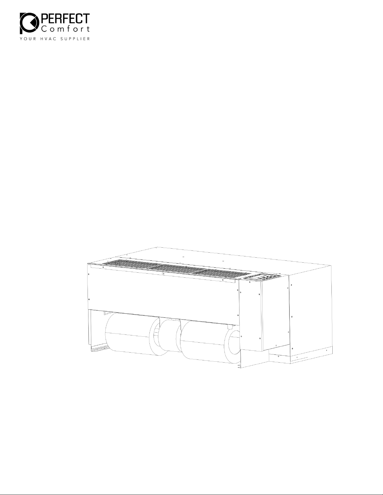
PCAA SERIES
PACKAGED TERMINAL
AIR CONDITIONER/HEAT PUMP
WITH UNIVERSAL HEATER
Installation, Operation and
Maintenance Manual
MODELS: PCAA09K235HTM3, PCAA12K235HTM3,
PCAA15K235HTM3
Page 2

Page | 2
Table of Contents
1. Read This First …………………………………………………………………………..………………………………..….…… 3
To the installer……………………………………………………………………………..………………………………….…… 3
General precautions ……………………………………………………………………..…………………………….....…… 3-4
2. Check List ……………………………………………………………………………………..…………………………….…….… 4-6
3. General Product Information ………………………………………………………..……………………………...….… 7
Product description ………………………………………………………………………..……………………………...…… 7
Standard controls and components ………………………………………………..…………………………………… 7
Operation Instructions ..…………………………………………………………………..……………………….…………. 8
Manual Control to Thermostat Instructions …………………………………………………………………………. 9
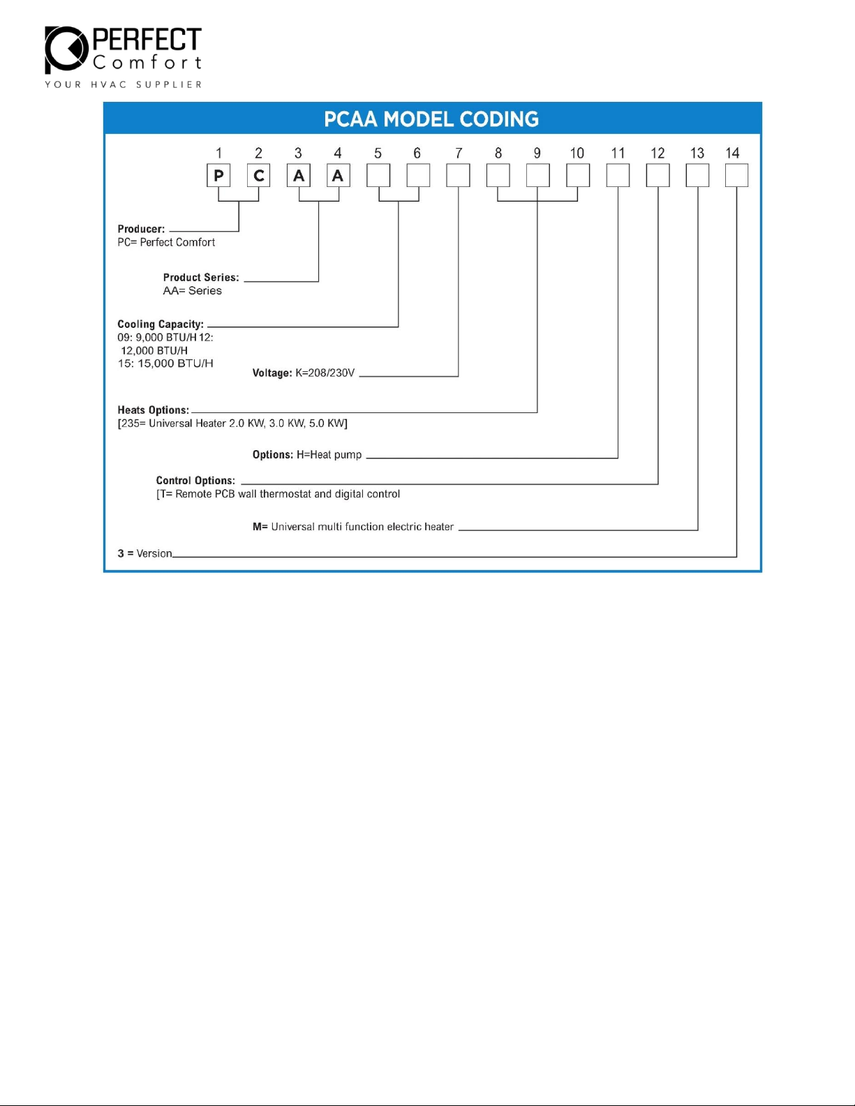
Model coding …………………………………………………………………………………..……………………………..…… 10
4. Preparing for the installation ……………………………………………………………………………………………… 11
Electrical supply ………………………………………………………………………………………………………………….. 10
Electrical short hazard ………………………………………………………………………..…………………………….… 11
Removing old chassis ……………………………………………………………………………………..…………………… 12
Check existing sleeve ……………………………………………………………………………………..…………………… 12
Check existing outdoor louver ………………………………………………………………………..……………..…… 12
5. Installation instructions ………………………………………………………………………………….……………….… 12
Chassis installation …………………………………………………………………………………………….…………….… 12
Wall thermostat installation ……….……………………………………………………………………….…………….. 13
Power Cord Installation…….…………………………………………………………………………………….………….. 13
Filter Installation ……………………………………………………………………………………………………..……….… 14
6. Final inspection and start up ………………………………………………………………………………………….….. 15
Final check list …………………………………………………………………………………………………….................. 15
Start-up ……………………………………………………………………………………………………………………..………. 15
Wall Thermostat ………………………………………………………………………………………………………..………. 15
7. Maintenance and Troubleshooting …………………………………………………………………………..………. 16
Monthly Inspection and Maintenance ………………………………………………………………………..……… 16
Seasonal Start-up and Maintenance …………………………………………………………………………….……. 17
Troubleshooting …………………………………………………………………………………………………………..……. 18-23
Error Code …………………………………………………………………………………………………………..…………….. 24
8. Performance Data ……………………………………………………………………………………………………………… 24
9. Warranty ……………………………………………………………………………………………………………………………. 25
Page 3
Page | 3
TO THE INSTALLER
Retain this manual for future reference. For further assistance please call 1-866-233-4022.
Before leaving the premises, review this manual to be sure the unit has been installed correctly and
run the unit for one complete cycle to make sure it functions properly. To obtain technical service or
warranty assistance during or after the installation of this unit, contact your local representative.
When calling for assistance, please have the following information ready:
1. Model number
2. Serial number
3. Date of installation
NOTICE
Due to ongoing product development, product designs and specifications may change without
notice. Please contact Perfect Comfort for more information.
Electric shock hazard
Turn off electric power before service or installation.
Don’t use this unit if it has damaged wiring, is not working properly, or has been damaged or
dropped.
Read these instructions carefully and completely before attempting installation. Unit should be
installed by qualified service technician ONLY.
Failure to do so can result in property damage, personal injury and/or death.
WIRE SIZE: Use ONLY wiring size recommended for single outlet branch circuit.
FUSE/CIRCUIT BREAKER: Use ONLY type and size fuse or HACR circuit breaker indicated on
receptacles and fuse type (see Table 01). Proper current protection to the unit is the responsibility
of the owner.
GROUNDING: Unit MUST be grounded from branch circuit through service cord to unit, or through
separate ground wire provided on permanently connected units. Be sure that branch circuit or general
purpose outlet is grounded.
Do not modify the PERFECT COMFORT PTAC POWER CORD
WARNING
DANGER
Page 4
Page | 4
The power cord should be checked before every use. Do not use the product if the cord has failed
the test. A damaged power cord must be replaced with a new cord from the manufacturer and not
repaired. The use of extension cords is prohibited.
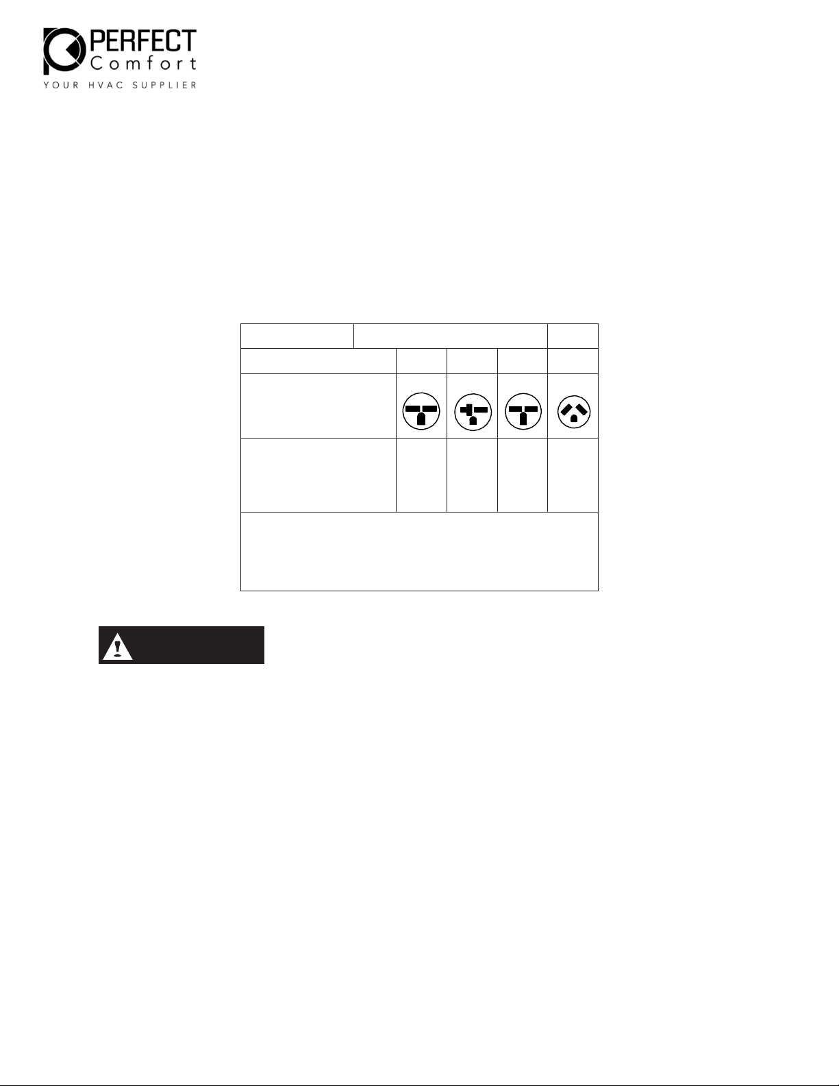
RECEPTACLE: The field supplied outlet must match plug on service cord and be within reach of
service cord. Refer to TABLE 1 for proper receptacle and fuse type
Failure to follow these instructions can result in a fire, explosion or electrical shock, causing property
damage, personal injury or death.
Table 01: Receptacles and Fuse Type
Table 1
250V
265/277V
AMPS
15
20
30
20
RECEPTACLE
TIME - DELAY
TYPE FUSE
(or HACR circuit
breaker)
15 20 30 20
HACR — Heating, Air Conditioning, Refrigeration
May be used for 15 Amp applications if fused for 15 Amp
Note: 265/277 – volt units require use of accessory subbase to meet NEC
and local codes.
Sheet metal parts, self-tapping screws, clips and such items inherently have sharp edges, and it is
necessary that the installer exercise caution.
This equipment is to be installed only by experienced installation company which employs trained
technicians.
PTAC chassis are heavy. To avoid injury, use assistance when lifting.
Check List
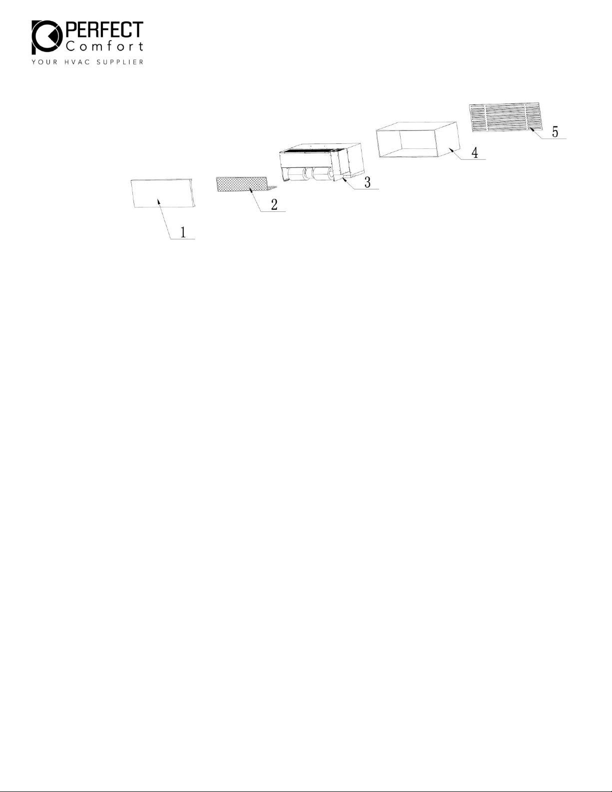
When the equipment is received, all items should be carefully checked - refer to typical configuration
(see Fig.01). All units should be carefully inspected for damage when received. If any damage is noticed,
the carrier should make the proper notation on the delivery receipt acknowledging the damage.
Please call 1-866-233-4022 for customer service.
CAUTION
Page 5
Page | 5
1. Front Door/Panel
- The tabs or inserts that connect to wall sleeve/cabinet should be checked. (Sold Separately)
2. Filter
- Filter is placed near bottom of unit and/or in the front panel. Confirm the size of filter(s)
available as sizes vary.
3. Cooing Chassis
- The unit nameplate should be checked to make sure the voltage agrees with the power
supply available.
- Verify that the indoor blower wheels and outdoor fan are rotating freely.
- Verify the compressor and tubing in proper position and perfect status.
4. Sleeve
- The sleeve should be checked that the inside dimensions will fit the PTAC. (Sold separately)
5. Louver
- The dimensions for the louver should be checked and compared with the sleeve. It must
match and fit inside the sleeve. (Sold separately)
Fig.01: Typical Configuration
Page 6
Page | 6
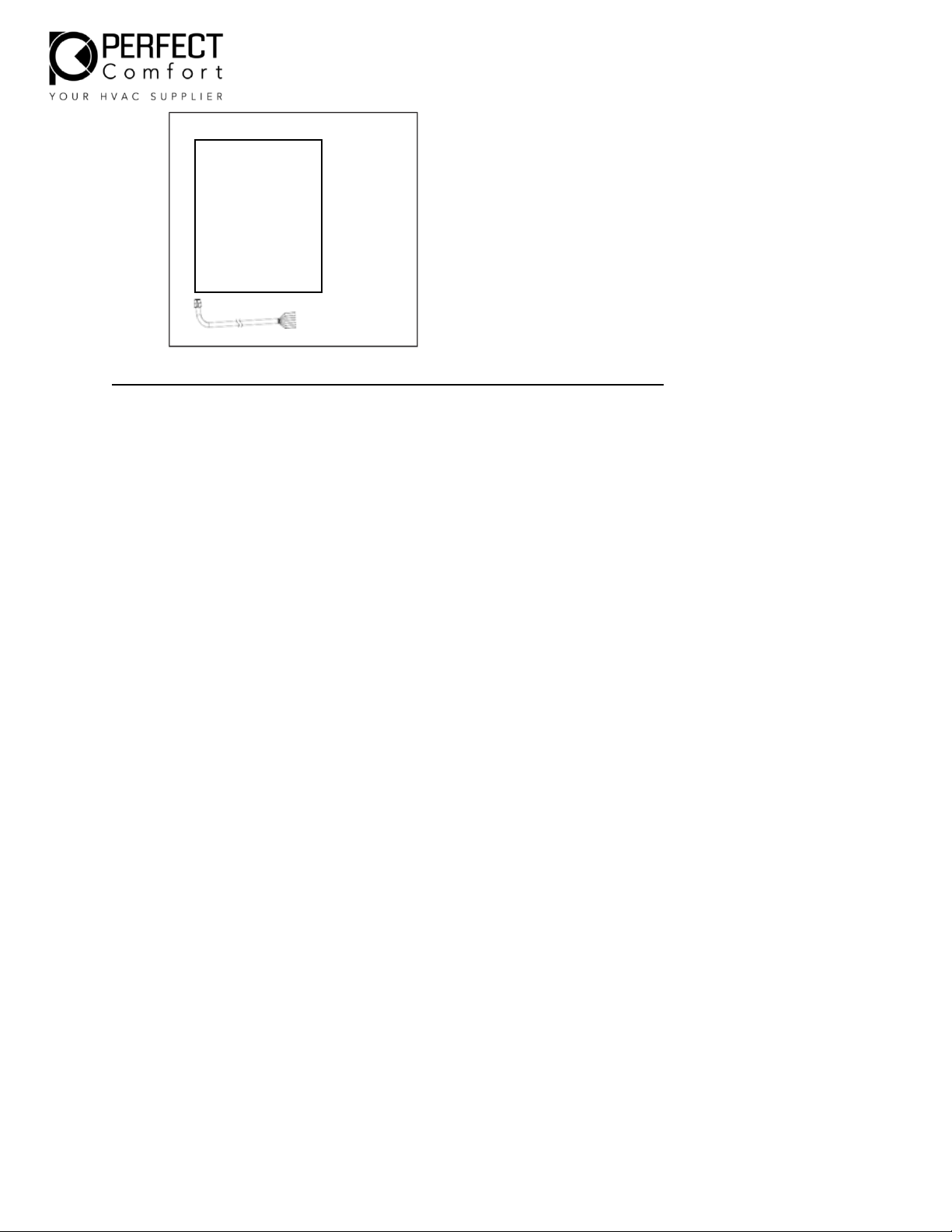
For this replacement PTAC only 2 (Filter) and 3 (Cooling Chassis) are provided.
Thermostat Wiring Harness and
Manual located in plastic bag.
Installation,
Operation and
Maintenance
Manual
Page 7

Page | 7
General Product Information
Product Description
Perfect Comfort replacement package terminal air conditioners have a cooling chassis with electric heat.
The PERFECT COMFORT PTAC unit
1. Use R410A refrigerant. This refrigerant is not affected by a phase out schedule. R410 is
environment friendly.
2. Include high-efficiency rotary compressors protected by a 6-year warranty
3. Offer three speed for evaporator fan motor, and one speed for condenser fan motor
4. Condensate removal system with dual drain hose, re- evaporation to improve efficiency
5. Heat Pump efficient operation
6. Digital control with optional thermostat hookup
7. Universal electric heat
2.0 KW heat can be obtained when 15A power cord is used at 230V. Part Number PC15UP.
3.0 KW heat can be obtained when 20A power cord is used at 230V. Part Number PC20UP.
5.0 KW heat can be obtained when 30A power cord is used at 230V. Part Number PC30UP.
PTAC units are available in nominal sizes of 9,000BTU, 12,000BTU or 15,000BTU
Standard control and components
Construction
1. 18 gauge galvanized steel and powder-coated for base pan and bulkhead, 20gauge
galvanized steel and powder-coat for construction.
2. Centrifugal evaporator fan with galvanized steel
3. Plastic fan blade for condenser
4. 20 gauge galvanized steel and powder coated for drain pan
5. Easily removable electric heater and easy access electrical box
6. Motors are thermally-protected.
7. Intelligent Control Board with digital control and optional thermostat control
(thermostat sold separately).
8. Washable filter
9. Metal protective discharge grille
Condensate removal system
1. Drain hose leads condensate to the outside base pan.
Slinger wheel, which is apart of the outdoor fan blade, throws condensate onto the condenser coil
during operation, where it evaporates, improving system performance.
Page 8
Page | 8
Operation Instructions
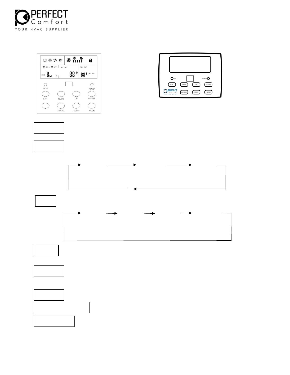
ON/OFF button: When unit is off; press this key to turn the machine on. When the
machine is on, press this key to turn off the unit. Use the mode button to select
heat/cooling or fan options.
MODE button: Mode selecting key, press the key, mode change as follows.
cooling fan mode heating
Fan button: Fan selecting key, fan speed as followed.
low fan med fan high fan auto fan
Timer button; Pressing further will forward 1hr increase, each press adds 1hr, up to
24hr.
UP & Down button: used to adjust the up and down of temperature. Press once to
increase the set temperature by 1oF, Press once to DOWN, the set temperature by
1oF.
Cancel button: Canceling timing setting
Press + hold “Down” button for 15 seconds to display Room Temperature.
Press and hold “Up” and “Down” buttons together for 15 seconds to switch
from C to F.
Controls
ON/OFF
MODE
FAN
TIMER
UP/DOWN
CANCEL
ROOM TEMPERATURE
Degree’s C to F
Page 9
Page | 9
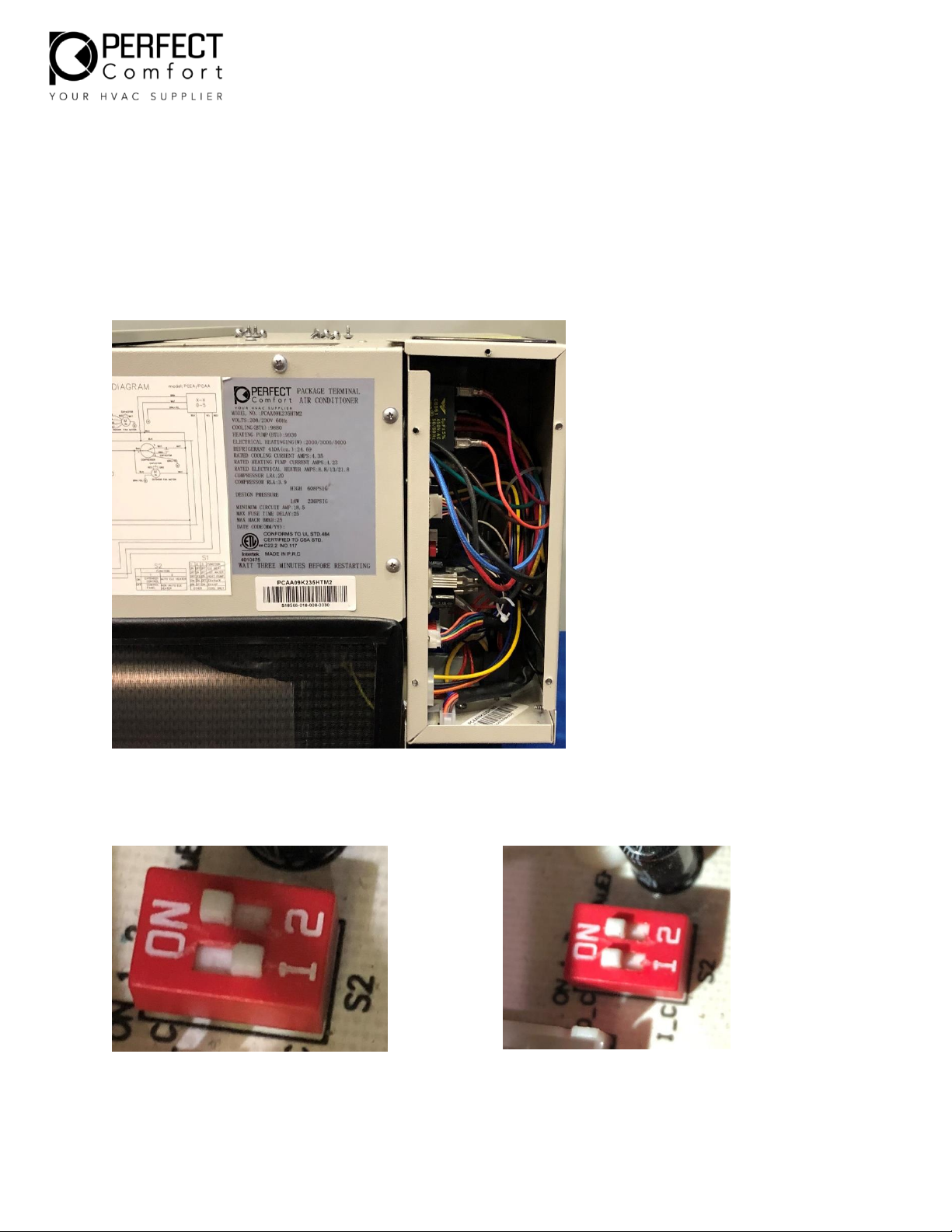
How to Change from Manual control to Thermostat for PCAA
Please follow the instructions and pictures
Step 1. Take the unit out of its sleeve
Step 2. Remove the front grill to access the display panel (DO NOT drop anything in fan unit )
Step 3. Remove the control panel to reach to the main board.
Step 4. Turn Dip Switch No. 1 from OFF to ON. (This pair of “1,2”.
Image of Dip Switch Off (Switch #1)
Image of Dip Switch On (Switch #1)
Page 10
Page | 10
Page 11

Page | 11
PREPARING FOR THE INSTALLATION
Safety Precautions
1. This unit should be installed by a factory certified technician or a licensed mechanical contractor
to ensure proper operation and avoid any safety hazards.
2. Power supply wires must be located in areas where they will not be damaged or cut.
3. Never insert any type of object into the machine inside. Because the fan rotates at a high speed,
this may cause injury.
4. Disconnect the power supply from socket-outlet when the machine units are not in use.
5. Disconnect all electric power supplies before servicing.
6. Any type of repairs or maintenance done to the units must be done by a professionally licensed
contractor. Any unqualified person should not attempt to repair the units themselves.
7. WARNING: RISK OF ELECTRIC SHOCK: CAN CAUSE INJURY OR DEATH.
8. Be sure that the unit is free and clear of any debris around the outside of the unit. Do not place
or lean any items on the unit.
Moving parts can cause personal injury. Avoid contact with moving parts when testing or
servicing the unit.
Electrical supply
Each unit must have a separate branch circuit protected by a fuse or breaker. Refer to the unit
rating plate for the proper wire and breaker or fuse size
Use of extension cords is prohibited
DO NOT connect the PERFECT COMFORT unit to a circuit with an incorrectly sized overcurrentprotection device
Electrical short hazard
Before opening the existing unit:
Open the power supply disconnect switch. Secure it in an open position during installation.
Attach a sign stating," DO NOT TURN ON"
On a plug and receptacle connection, unplug the existing unit at the wall outlet.
DO NOT plug in the new unit until installation is complete and the start-up check list has been
completed. Failure to comply with the above could result in severe personal injury, death or
substantial property damage.
WARNING
Page 12
Page | 12
Remove the old chassis
1. Disconnect power or unplug cord before proceeding
2. Remove the front panel to expose the old chassis
3. Loosen any tie- down bolts or screws and remove the old chassis
Check existing wall sleeve
PERFECT COMFORT replacement PTAC’s are to be used with a metal wall sleeve:
a) Clean the wall sleeve of any dirt
b) Repair any damage or rust
c) Ensure proper drainage of condensate or rainwater to exterior of building
d) Check the back of sleeve is pitched to the outside ¼ bubble on level
e) Check the sleeve is leveled left to right
f) Make sure the wall sleeve is secured in the wall
Check existing outdoor louver
Check whether the type of the outdoor louver match the baffle and insulation on the chassis,
adjust if it doesn’t match.
Remove any obstructions
INSTALLATION INSTRUCTIONS
CHASSIS INSTALLATION
1. Check the seal foam on the rear of chassis, make sure to avoid ventilation recirculation
2. Slide the chassis into the sleeve tight to the end of the sleeve.
3. Secure the chassis —tighten any tie down bolts or screws if necessary.
Fig. 03
Page 13
Page | 13
WALL THERMOSTAT INSTALLATION
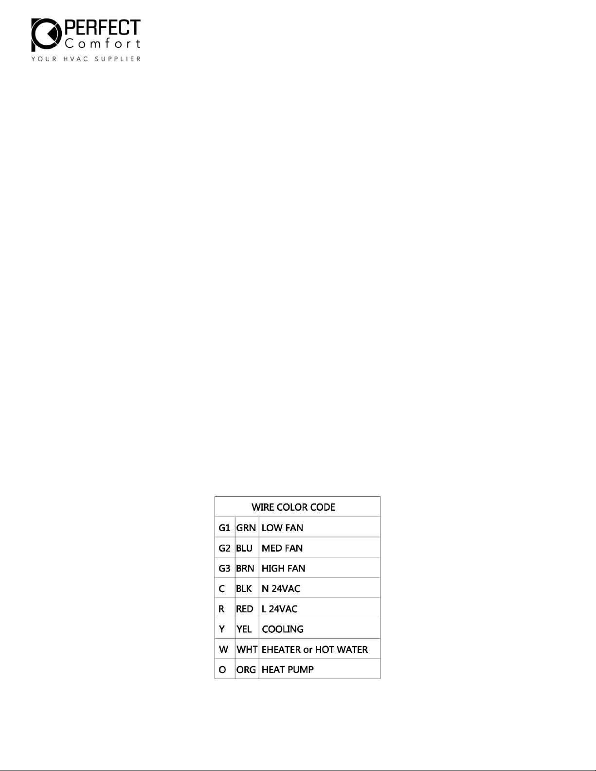
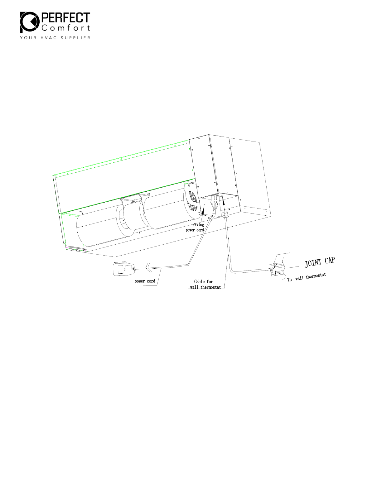
Connect the wall thermostat cable with the chassis. See Fig.03 for wire colour coding.
Install the wall thermostat as per instructions from thermostat manufacturer. Connect cable from
chassis to the existing wires in the wall as Fig.04
Ensure to wrap and make protection at the joint points.
If thermostat is still not working, please refer to page #9
POWER CORD INSTALLATION
Connect Universal Power Cord to female connection on unit. See Fig 04. The connection will
clip in place and can be removed in future be compressing the sides and pulling the cord free.
Once the cord is connected securely to the unit plug cord into wall outlet. Once cord is
plugged in, confirm the LED light on the head of the plug is on.
Fig.04 Cable Connection for Wall Thermostat and Universal Power Cord
Page 14
Page | 14
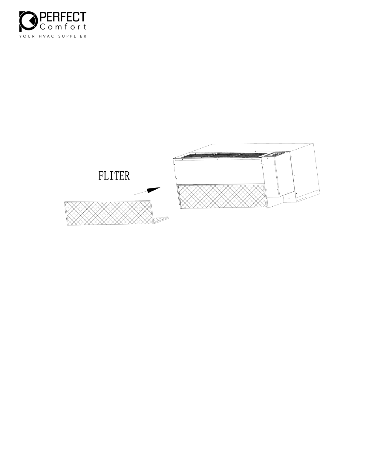
FILTER INSTALLTION
Filter is installed by sliding into slots near the bottom of the unit where th e fan housing is
located. The filter should be inserted fully until the vertical piece of the filter is flush with the
front of the unit. Once the filter is in place, the cover can now be installed.
Fig. 07
Page 15

Page | 15
FINAL INSPECTION AND START-UP
Check list
1. Ensure the chassis is secured with the sleeve
2. Unit is installed in compliance with all codes
3. Circuit breakers and wire sizes are correct
4. Ensure the electrical supply matches the electrical requirements of the unit, and that
the unit is properly grounded
5. Check whether the electric heat match the power cord
6. Filter clean and in place
7. All panels in place
8. Make sure the chassis is leveled 1/4 bubble towards exterior
9. Verify that nothing will interfere with the room discharge air or the return air of
the units
Examples:
- Check for curtains or drapes that obstruct the air flow
- Check for plush carpeting that can obstruct the return air
- Items like these can cause serious damage to the chassis
- Ensure work area clean and free of debris
Start-up
- Plug the power cord to the receptacle
- Turn on the chassis, and operate all functions
Wall Thermostat
See wall thermostat instructions to operate thermostat. Test all functions to confirm PTAC unit is
working properly.
Page 16

Page | 16
Maintenance and Troubleshooting
Monthly inspection and maintenance
Electrical shock hazard. Disconnect power to the PERFECT COMFORT replacement PTAC before servicing
or accessing the control compartment. Failure to do so could result in severe personal injury or death.
It is illegal to discharge refrigerant into the atmosphere. Use proper reclaiming methods and equipment
when servicing a perfect comfort replacement PTAC.
For optimum performance and reliability of your PERFECT COMFORT replacement PTAC, PERFECT
COMFORT recommends performing the following sections and maintenance on a monthly basis.
Units that are installed in harsh or dirty environments will require more frequent inspections and
maintenance.
- Clean or replace the indoor air filter
- Vacuum return air grille surface
- Inspect & clean the chassis interior for rodent or insect infestation
- Clean & flush condensate drain pan and chassis base pan
- If applicable, ensure the condensation drain is functioning properly
- Inspect refrigeration tubing; especially braze joints, for signs of refrigerant leaks. (oil
residue) repair if necessary
- Inspect indoor and outdoor coils. Ensure dirt or debris has not collected on the fins. Clean if
necessary. Be careful not to damage coil fins when cleaning. Use a fin comb to straighten
any bents fins.
- Examine control box. Ensure all wire connections are secure
- Ensure indoor blower wheel and outdoor fan blades are secured to their motor shafts
- Ensure dirt or debris has not collected on the indoor blower wheels and outdoor fan blades.
Use a vacuum and soft brush
- Clean the exterior of the cabinet as desired with a mild soap or household cleaner
DANGER
WARNING
Page 17

Page | 17
Clean or replace the return air filter as needed. Allowing dust to collect on the filter will cause the unit
to lose efficiency and eventually malfunction. Check the filter at least once a month. Some environments
may require more frequent replacement, depending on particulate in the air stream.
NOTICE
If a new air filter is needed for your PERFECT COMFORT replacement PTAC, consult supplier for
availability and/or proper sizing.
SEASONAL START-UP AND MAINTENANCE
At the beginning of the cooling and heating seasons, a complete mechanical check should be performed,
and maintenance/inspections performed as described below. Disconnect power to unit and remove
necessary access panels
1. Performing the inspections and maintenance defined in “Monthly start-up and Maintenance”
2. Do a visual check of the equipment. Look for obvious changes in the unit such as damaged coils or
evidence of extended wear on any moving parts.
3. Check for unusual odors, oil leaks, or stains on or around the coils and refrigerant lines. The presence of
oil here may indicate a potentially serious problem such as a refrigerant leak.
4. Make sure the base pan is clean
5. Inspect all electrical connections. Look for frayed wires and poor connections. Terminal ends that are
loose will eventually fail, causing a loss of performance or worse.
6. Check fan motors and blower assemblies. Some units may require a drop of light oil to motors and/or
bearing assemblies (look for oil cups) ensure setscrews and motor mounting hardware are tight.
7. Brush and/or Vacuum the centrifugal fan blades ad blower cage assemblies as they must be clean to
operate efficiently.
WARNING: Do not use a solvent-based cleaner to clean coils, as some solvents will produce a noxious
odor when the unit is in operation.
8. Inspect both indoor and outdoor coils. Use a fin comb to straighten out any damaged fins. These coils
must be straight and free of any debris.
9. Inspect and clean the drain pan and drain line(s). The use of anti-fungicide tablet to keep the condensate
system free from bacterial contaminants is recommended.
10. Check the pitch of the unit. Over time the building and equipment may settle, causing a shift in the
direction of the condensate flows. Ideally the unit should pitch a minimum of ¼ bubble on level to the
outside to allow for proper drainage.
11. Check drainage holes along rear flange of the base pan to ensure they are free of debris.
12. Check to ensure the seal around the unit is not broken or damaged.
Notice: Air leaks may make the conditioned area uncomfortably drafty or produce noises. Visually inspect
the foam gasket between the wall and the unit, especially taking note of the separation between the air
inlet for the condenser and the condenser coil discharge. These two areas must be sealed off from each
other. If you experience poor cooling operation or erratic operation, check for air recirculation at the
condenser coil.
13. Replace the access panels and reconnect the electrical power.
14. Test the unit operation.
WARNING
Page 18
Page | 18
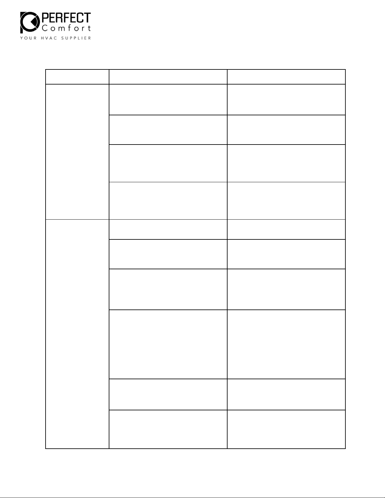
TROUBLE SHOOTING GUIDE
SYMPTOM
CAUSE
CHECK/CORRECTION
Thermostat does
not properly
control room
temperature, runs
continuously or
causes abnormal
cycles in heating
or cooling mode
Sleeve seals are worn or missing
allowing outdoor air to be passed
over the thermostat sensing bulb
Inspect and replace if necessary
Defective thermostat
Test and replace if necessary
Thermostat bulb/sensor not
properly located
Ensure bulb is clipped to evaporator
coil at original factory specified
location
Thermostat/sensor temperature
limiting option not set up properly
Set up the temperature limiting option
according to the unit installation
instructions
Compressor Short
Cycles
Low Voltage
Check voltage with unit running and
ensure it is within nameplate limits
Restricted condenser air
Check for dirt or other condenser coil
restriction. Clean as necessary
Recycling of condenser air
Check for inadequate discharge air
installation clearances. Coil not sealed
against grille, unit may not be
completely pushed into sleeve
Condenser fan motor operating
intermittently, rotating slowly, or
not at all
Check to see if fan or shaft is being
rubbed or experiencing external
friction. Check free rotation of the
motor shaft. Check voltage to the
motor. Check motor capacitator. Check
for mis-wiring. Motor may have open
windings, or internal overload is
defective. If so, replace motor
Thermostat bulb/sensor not
properly located
Ensure bulb is clipped to evaporator
coil at original factory specified
location
Faulty or incorrect compressor
overload
Check for correct overload model
number and replace if incorrect.
Otherwise, if running amps seem
normal, replace overload.
Page 19
Page | 19
SYMPTOM
CAUSE
CHECK/CORRECTION
Compressor Short
Cycles (Cont.)
Indoor coil frozen
See “Evaporator Coil Frosts”
Recycling of indoor air
Ensure that curtains or other
obstructions are not short circuiting air
between the outlet grille and return air
intake
Compressor running too slow and
drawing high amps
Compressor may be mis-wired. Check
capacitator. Compressor may be
seizing – if so, replace compressor
Compressor will
not run
Fuse or circuit breaker tripped
Replace or reset as necessary
Defective switch
Test and replace if necessary
Defective thermostat/sensor
Test and replace if necessary
Indoor room temperature below
thermostat set point
Lower thermostat setting if comfort is
not yet achieved
Indoor room temperature below
65’F
Cooling will not operate if the room
temperature is below 65’F
Outdoor temperature too cold
Compressor is not intended to operate
at cold outdoor temperatures
Broken, shorted, loose or mis-wired
wiring
Inspect and correct
Defective compressor capacitor
Test and replace if necessary
Defective compressor overload
Test and replace if necessary
Low voltage or no voltage to
compressor
Check voltage and ensure it is within
nameplate limits
Page 20
Page | 20
SYMPTOM
CAUSE
CHECK/CORRECTION
Compressor will
not run (Cont.)
Compressor windings open
Disconnect overload from compressor
terminals. Check for winding resistance
across all winding pairs. C-S, C-R, S-R
and check each terminal to the
compressor shell for ground faults.
Replace compressor if any windings are
open-circuited or short circuited to the
shell
Seized compressor
If all of the above check out OK and if
pressures are equalized, and
compressor draws high amps and will
not start, the compressor is seized and
needs to be replaced
Unit Trips Fuse/
Circuit Breaker
Shorted or incorrect wiring
Check all connections. Also check for
shorts within devices such as motors,
switches, heater, etc.
Shorted capacitor
Test and replace if necessary
Compressor short cycling
See “Compressor Short Cycles”
Power was interrupted to the unit
Wait three minutes before starting
Fuse or breaker setting too low
Check nameplate fuse size
Broken, shorted, loose or mis-wired
wiring
Inspect and correct
Low voltage or no voltage
Check voltage with unit running and
ensure it is within nameplate limits
Seized or slow running compressor
See above
Page 21
Page | 21
SYMPTOM
CAUSE
CHECK/CORRECTION
Evaporator Coil
Frosts
Dirty air filter
Clean or replace
Dirty evaporator coil
Clean as necessary
Blower motor operating
intermittently, rotating slowly, or
not at all
Check to see if blower wheel or shaft is
being rubbed or experiencing external
friction. Check free rotation of the
motor shaft. Check voltage to the
motor. Check motor capacitor. Check
for mis-wiring. Motor may be seizing.
Motor may have open windings, or
internal overload is defective – if so,
replace the motor
Low refrigerant charge
Look for telltale signs of low charge.
For example, check the frosting pattern
starting from defrosted condition. If
the whole evaporator face frosts
uniformly at the same time, it indicates
that the unit has insufficient indoor
airflow. If the frost works its way up
the face of the evaporator during
operation over time, it indicates low
charge, low running amps, low or no
sub cooling and excessive superheat
are other signs of undercharge. Find
and fix the leak and recharge R410A to
the nameplate charge
Faulty thermostat
Test and replace if necessary
Page 22
Page | 22
SYMPTOM
CAUSE
CHECK/CORRECTION
Unit Rattles or is
Noisy
Defective compressor
Check and replace if necessary
Refrigerant line hitting surroundings
Bend tube slightly to obtain clearance
Loose fan, blower, or motor mounts
Check and tighten if necessary
Rubbing of fan or blower on
housing
Ascertain cause and correct. Check
during operation
No Heating
Faulty thermostat
Test and replace if necessary
Fuse or circuit breaker tripped
Replace or reset as necessary
Cord not plugged in
Plug in
Defective switch
Test and replace if necessary
Defective heater
Inspect and replace if necessary
One-time thermal fuse is blown
Check thermal fuse for open circuit and
replace if necessary
Automatic reset high limit control
will not reset
Check high limit for open circuit and
replace if necessary
Broken, shorted, lose or mis-wired
Inspect and correct
Indoor room temperature above
thermostat set point
Raise thermostat setting if comfort not
yet achieved
Page 23
Page | 23
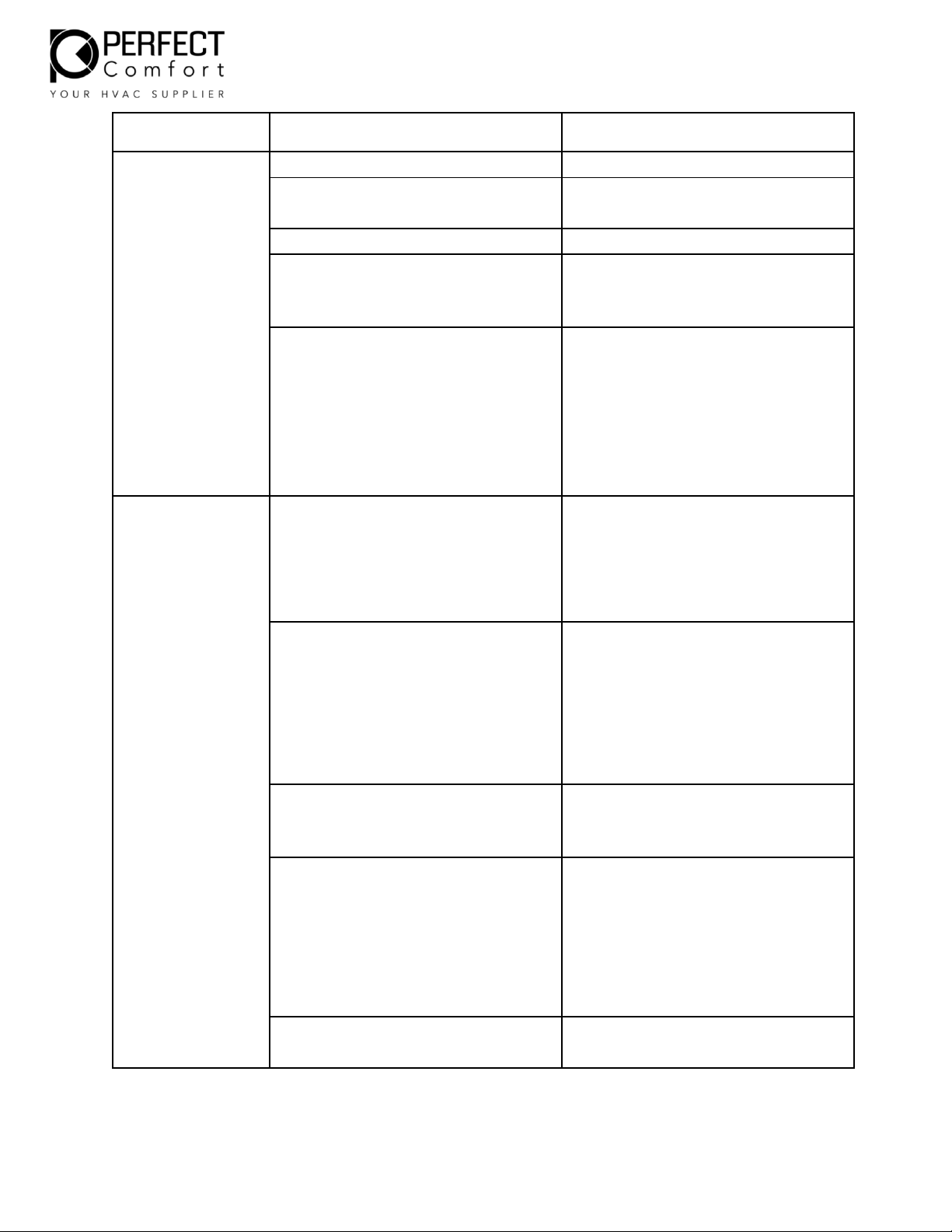
SYMPTOM
CAUSE
CHECK/CORRECTION
Heater Output
Intermittent or
Insufficient
Faulty thermostat
Test and replace if necessary
Automatic reset high limit control
calibration defective
Replace high limit
Dirty air filter
Clean or replace
Dirty evaporator coil
Clean as necessary
Blower motor operating
intermittently, rotating slowly, or
not at all
Check to see if blower wheel or shaft is
being rubbed or experiencing external
friction. Check free rotator of the
motor shaft. Check voltage to the
motor. Check motor capacitor. Check
for mis-wiring. Motor may be seizing
internally or internal overload is
defective – if so, replace motor
Water Drips from
Unit
Sleeve not properly mounted
Check sleeve for the required 3/8”
pitch down from indoor to outdoor
side and level side-to-side. Re-adjust as
required.
Condensate drain plugged
Clean condensate drain spout passing
through the dividing wall
Evaporator drain pan cracked or
improperly mounted
Inspect, re-align or replace plastic drain
pan as required.
Unusually high moisture content in
the indoor and/or outdoor air
Under certain ambient conditions
excessive condensate can be generated
beyond the capacity for the unit to
reject via evaporation to the outdoor
airstream. If objectionable of frequent,
connect to an internal drain system
with available optional drain kit.
Drain holes plugged in bottom edge
of sleeve on outdoor side
Inspect and clear blockage
Page 24
Page | 24
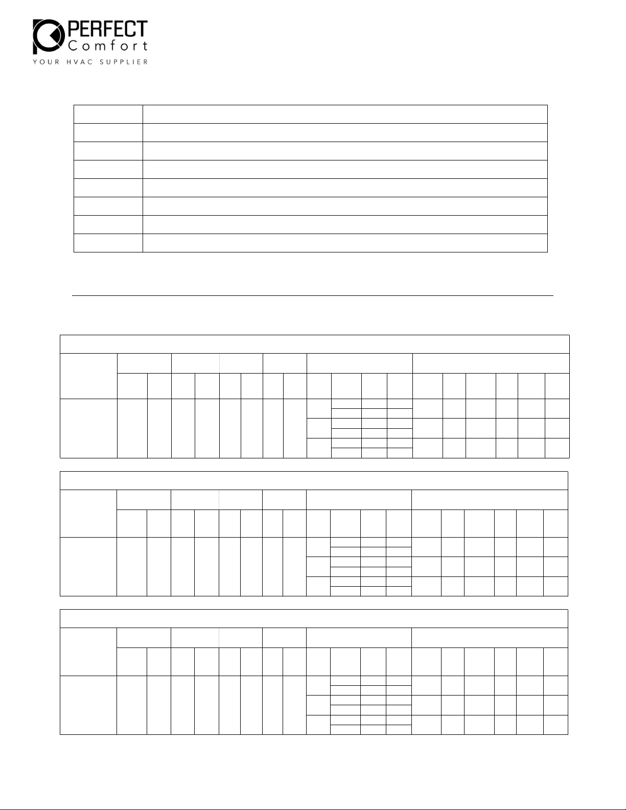
Error Codes
Error code
Error Presentation
E1
Indoor temperature sensor broken/short circuit
E2
Temperature sensor of indoor condenser coil broken/short circuit
E3
Outdoor environment temperature sensor broken/short circuit
E4
Protection of lack cooling liquid
E6
Pressure switch protection
E7
Position of DIP switch error
E8
Low temperature and low-pressure protection of outdoor cold water
Fan Motor
Electric Heat
Unit Electrical Ratings
Motor
Outdoor
Compressor
Indoor Fan
Power Supply
Volt
PCAA Air Conditioner with Electric Heat
208/23
0
PCAA15K235HTM2
Model
0.1
0.55390.5
197
6.55
2KW
7.5
0.12
7.5
5KW
3KW
6.5
6.5
6.5
7.5
9.5
22
13
8.81515
23146-25P
6-20P
6-15P
26
208 1725 8.2
230 2000 8.8
208 2525 12.1
230 3000 13
208 4050 20.5
230 5000 22
Plug
MAX
HACR
BRKR
Pump
A/Heating Max.AVolt Min RLA LRA FLA HP ELA HP HTR# Volt W HA A/Cooling
Heat
Fan Motor
Electric Heat
Unit Electrical Ratings
Motor
Outdoor
Compressor
Indoor Fan
Power Supply
Volt
PCAA Air Conditioner with Electric Heat
208/23
0
PCAA12K235HTM2
Model
0.1
0.55280.5
197
5.26
5KW
3KW
2KW
0.12
5.58
5.58
5.58
5.02
5.02
5.02
22
13
8.8
23
14
9.5
26
15
15
6-25P
6-20P
6-15P
208 1725 8.2
230 2000 8.8
208 2525 12.1
230 3000 13
208 4050 20.5
230 5000 22
Plug
MAX
HACR
BRKR
Pump
A/Heating Max.AVolt Min RLA LRA FLA HP ELA HP HTR# Volt W HA A/Cooling
Heat
Model
Fan Motor
Electric Heat
Unit Electrical Ratings
Motor
Outdoor
Compressor
Indoor Fan
Power Supply
Volt
PCAA Air Conditioner with Electric Heat
208/23
0
0.1
0.55200.5
197
3.9
PCAA09K235HTM2
5KW
3KW
2KW
0.12
4.35
4.35
4.35
4.23
4.23
4.23
22
13
8.8
23
14
9.5
26
15
15
6-25P
6-20P
6-15P
208 1725 8.2
230 2000 8.8
208 2525 12.1
230 3000 13
208 4050 20.5
230 5000 22
Plug
MAX
HACR
BRKR
Pump
A/Heating Max.A
Volt Min RLA LRA FLA HP ELA HP HTR# Volt W HA A/Cooling
Heat
Page 25
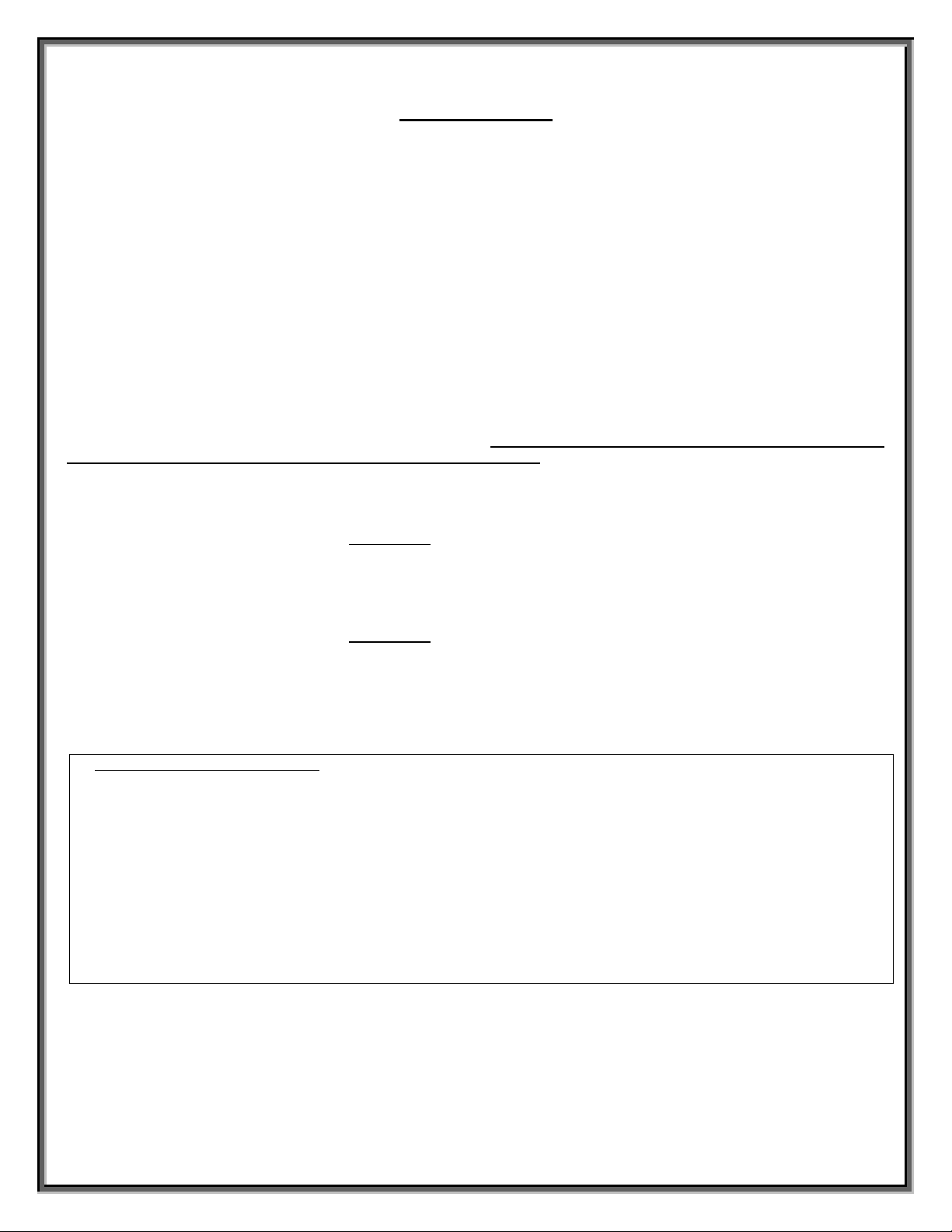
PERFECT COMFORT REPLACEMENT PACKAGED TERMINAL AIR CONDITIONER
WARRANTY FOR PRODUCTS PURCHASED AND USED
IN CANADA & USA
SAVE THIS CERTIFICATE.
BEFORE CALLING FOR SERVICE, carefully read your instruction booklet. In the event your Perfect Comfort product requires
servicing, contact your nearest authorized service centre. If you do not know the nearest service centre, contact the company
you purchased your Perfect Comfort product from or call Perfect Comfort at 1-866-233-4022. When requesting service, please
have the model number, serial number, date of purchase and a description of the problem available. Service will be provided
during normal working hours.
ESTABLISHING PROOF OF PURCHASE DATE
For warranty purposes, it is the customer’s responsibility to retain the bill of sale as proof of purchase. Failing to do so, the
effective date will be based upon the date of manufacture plus thirty (30) days or the date of shipment from Perfect Comfort.
STANDARD WARRANTY
Within one year of original purchase, Perfect Comfort will supply a replacement for any component part(s) found to be defective
in materials or workmanship. All replacement part(s) assume the unused portion of the original warranty. Within one year of
original purchase, Perfect Comfort will pay for labour costs for such repair work at our established labour rates. See Labour
Warranty Rates & Codes sheet for labour allowance. In the second through sixth year of warranty from the date of original
purchase, if the compressor is found to be defective, Perfect Comfort will supply a replacement part only. All replacement
compressor(s) assume the unused portion of the original warranty. No payments will be made without a Perfect Comfort approval
number. All approval numbers are issued prior to doing any warranty work.
EXTENDED 1 YEAR PARTS WARRANTY
After the first year starting from original purchase, for (1) additional year Perfect Comfort will supply a replacement for any
component part(s) found to be defective in materials or workmanship. All replacement part(s) assume the unused portion of the
original warranty. The extended warranty is not included with the unit and must be purchased within 30 days from purchase
date from Perfect Comfort.
EXTENDED 5 YEAR PARTS WARRANTY
After the first year starting from original purchase, for (5) additional years Perfect Comfort will supply a replacement for any
component part(s) found to be defective in materials or workmanship. All replacement part(s) assume the unused portion of the
original warranty. The extended warranty is not included with the unit and must be purchased within 30 days from purchase
date from Perfect Comfort.
LIMIT OF LIABILITY
The aggregate of all coverage and benefits paid or payable under this Limited Warranty shall not exceed the original price paid
for the product, less installation charges. If the aggregate limit is met, or if the product is replaced in its entirely, the maximum
liability will have been met under the Limited Warranty.
What is NOT included in the Warranty
• Charges for shipping, overtime rates, diagnosing equipment, and truck/vehicle usage.
• Replace house/facility fuses and/or circuit breakers, reset circuit breakers or correct house/facility wiring.
• Clean or replace air filters.
• Correct improper installations.
• All expenses where the Perfect Comfort product is subjected to improper installation, inadequate maintenance, abuse or
misuse, neglect, accident, fire, flood, or incorrect power source.
• The removal and reinstallation of the Perfect Comfort product, if it is installed in an overhead or other inaccessible location.
• Perfect Comfort products that have unauthorized modifications to electrical and/or mechanical components.
• Shipping charges to deliver the Perfect Comfort product to an authorized service depot and return to installation.
• Perfect Comfort products that have been moved from the original site of installation.
• All labour and service call charges incurred after the Standard Limited One Year Warranty has expired.
• Cost of replacement refrigerant and all other charges incurred after the Standard Limited One Year Warranty has expired.
• Service work by unauthorized technicians.
Service must be provided by a Perfect Comfort authorized service depot. All service calls and labour charges will be at our rate in effect at the
time of the service.
This warranty applies only while the Perfect Comfort product remains at the original site and only to Perfect Comfort products installed in
Canada & USA. Perfect Comfort shall not be liable for any indirect, incidental, consequential, or special damages in connection with any use or
failure of this product. No one is authorized to change this warranty or to create for us on our behalf any other obligation or liability in
connection with our product(s). There is no other warranty or condition in any respect, expressed or implied, made by or binding upon us other
than the above or as provided by provincial law and which cannot be limited or excluded by such law.
Model #_________________ Serial #_________________Install Date________________
May 1, 2019
 Loading...