

Perfect Aire 2VPTH09A-3.6, 2VPTH12A-3.6, 2VPTH15A-5.0 User Manual
FOR MODELS:
2VPTH09A-3.6
2VPTH12A-3.6
2VPTH15A-5.0
Before using your air conditioner please
read this manual carefully and keep it for
future reference, along with your receipt.
USER MANUAL
PACKAGED TERMINAL
AIR CONDITIONER
HEAT PUMP DC INVERTER
CONTENTS
UNIT FEATURES .............................................................2
INSTALLATION INSTRUCTIONS ....................................4
WIRING ............................................................................6
OPERATING INSTRUCTIONS.........................................7
ADVANCED OPERATION ................................................8
FUNCTION OF DIP SWITCHES......................................9
MAINTENANCE AND CLEANING .................................10
NORMAL OPERATING SOUNDS & CONDITIONS.......11
DIAGNOSTIC CODES & SOLUTIONS ..........................13
TROUBLESHOOTING ...................................................14
-1-
IMPORTANT NOTE TO THE SERVICER
Read this manual and familiarize yourself with the specific
items which must be adhered to before attempting to
service this unit. The precautions listed in this Installation
M
anual are intended as supplemental to existing
practices. However, if there is a direct conflict between
existing practices and the content of this manual, the
precautions listed here take precedence.
REC
OGNIZE THIS SYMBOL
AS A SAFETY PRECAUTION
THE MANUFACTURER WILL NOT BE RESPONSIBLE FOR ANY
INJURY OR PROPERTY, DAMAGE ARISING FROM IMPROPER
SERVICE OR SERVICE PROCEDURES. IF YOU INSTALL OR
PER FO RM S ER VI CE ON T HIS U NIT, YOU ASSU ME
RESPONSIBILITY FOR ANY PERSONAL INJURY OR PROPERTY
DAM AGE WHICH MAY RESULT, MANY JURI SDIC TION S
REQUIRE A LICENSE TO INSTALL OR SERVICE HEATING AND
AIR CONDITIONING EQUIPMENT.
WARNING
IMPORTANT NOTES:
Before using this manual, check the serial plate for proper
model identification.
The installation
and servicing of this equipment must be
performed by qualified, experienced technicians only.
Due to policy of continual product improvement, the right is
reserved to change specifications and design without
notice.
IMPORTANT NOTE TO THE OWNER
This manual is to be used by qualified, professionally trained
HVAC technicians only. The manufacturer does not assume
any responsibility for property damage or personal injury for
improper service procedures or services performed by an
unqualified Person.
THE
FOLLOWING WARNINGS ARE
VERY IMP ORTANT FOR SAF ETY.
PLEASE READ THEM CAREFULLY
BEFORE INSTALLATION!
1. The air conditioner must be installed by
certified installer.
2. Check whether there is grounding wire
in the power supply system before
installation. If not, installers should refuse
installing and explain the safety principle to
users.
3. To avoid electric shock or even death,
the
socket or terminal blocks for power
supply to the air conditioner (include
277V and 115V and 208~230V series
and the units that have LCDI power
cord) must connect a Ground Fault Circuit
Interrupter.
4. During installation, the wire
connection must strictly follow the rule
zero line and fire line of unit should
be connected to the zero line and fire line
in the power system. The connection
in reverse is forbidden. Please be sure
the ground wire is firmly connected
otherwise it is possible to result in the
electrical shock or death.
WARNING
HIGH VOLTAGE
DI SCONNECT ALL P OW ER B EFO RE S ERV ICING O R
INSTALLING THIS UNIT. MULTIPLE POWER SOURCES MAY
BE PRESENT, FAILURE TO DO SO MAY CAUSE PROPERTY
DAMAGE, PERSONAL INJURY OR DEATH.
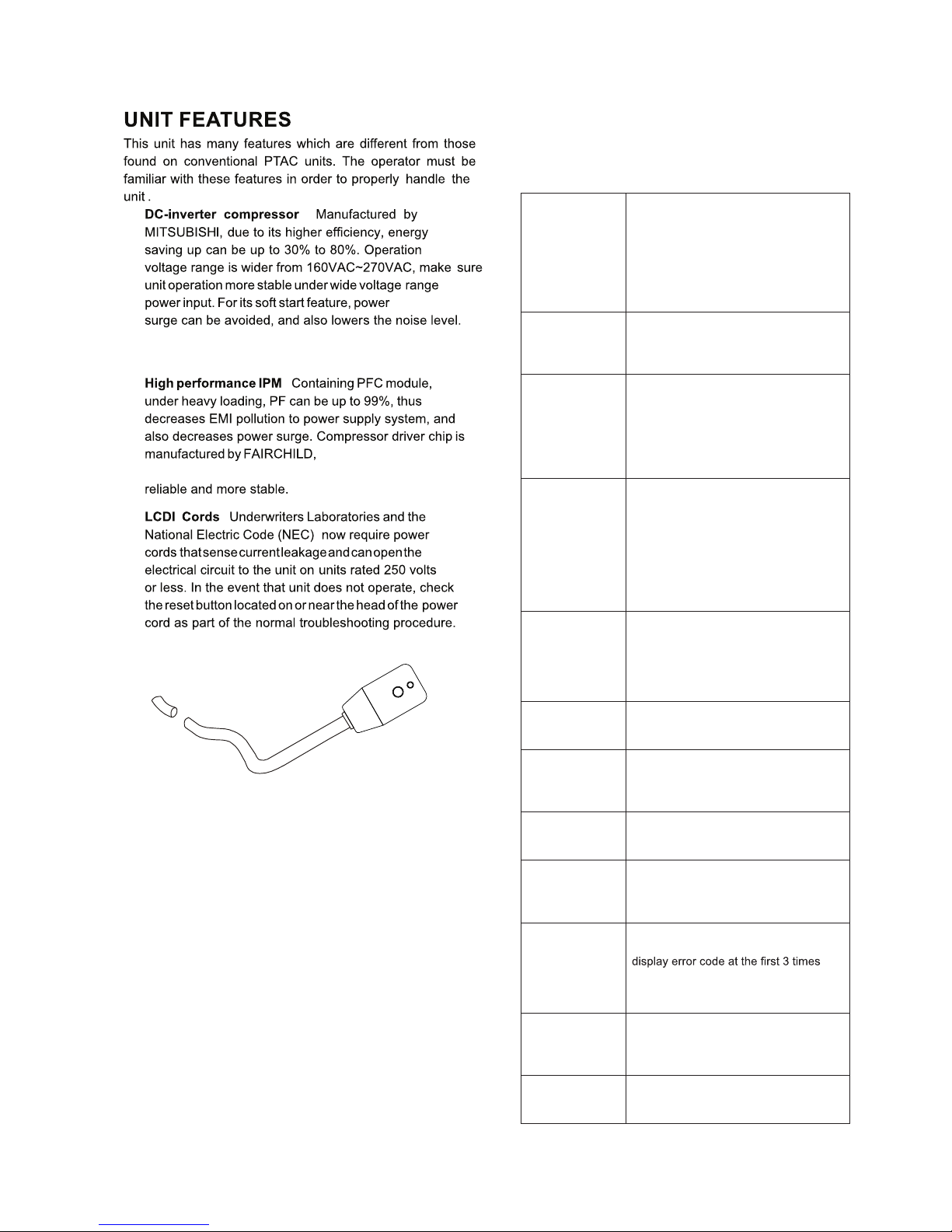
LCDI power Cord
Automatic 3-minute compressor lockout: After
the compressor cycles off, it will not restart for three
minutes.
Random restart delay: To help eliminate power
surges after a power outage, the unit is equipped with
two to four minute random restart delay feature.
Whenever the unit is plugged in with the master
switch turned on and the mode switch set in the cool
or heat mode, a random restart will occur. A random
restart condition can be avoided by setting the mode
switch in the fan only or off position before applying
power to the unit.
Indication LEDs : The control panel has LEDs that
correspond to fan operation and to indicate unit status.
The LEDs next to the selections ON/OFF, FAN, COOL,
and HEAT indicate which mode is active.
- 2 -
Without frequently starting-stopping, the room
temperature is more stable & more comfortable.
a known brand providing
high performance, making the compressor more
:
:
System safety protection
To ensure the system is running safely, the electric
control has the following protections. For problem
solving, please refer to Diagnostic Codes & Solutions
and Troubleshooting sections, pages 13 & 14.
When condenser coil temperature exceeds the presetting point, compressor
decreases the operating frequency to
30Hz. If this protection is inactive and
condenser coil temperature reaches the
shut-down point, the compressor will
be turned off. Thus providing double
protection.
Outdoor unit
overload
protection in
COOLING mode
Evaporator freeze
protection (will
not display error
code)
When evaporator coil temperature drops
to 1°C and lasts for 5 minutes, compressor and outdoor fan will stop, indoor fan
keeps on running.
When compressor discharge temperature reaches protection point, compressor will decrease operating frequency
to 30Hz. If this protection is inactive and
discharge temperature reaches the shut
down point, compressor will be turned
off. Thus provide double protections.
Compressor
discharge
overheating
protection
When evaporator coil temperature
exceeds the presetting point, compressor decreases the operating frequency
to 30Hz. If this protection is inactive and
evaporator coil temperature reaches
the shut down point, compressor will
be turned off. Thus provide double protections. This time the back up electric
heater will be turned on.
Evaporator
overload
protection
(heat pump
mode)
When input current exceeds the presetting point, compressor will decrease
the operating frequency to 30Hz. If this
protection is inactive and current reaches the shut down point, compressor will
be turned off.
Input over
current
protection
Compressor over
current protection
When compressor operating current exceeds the shut down point, compressor
will be shut down.
When IPM faults, include over heat,
unit will be shut down, all outputs are
terminated, control panel displays the
error code.
IPM fault
protection
Temperature
sensor fault
Any temperature sensor faults, unit
stops and display the error code.
protection
For continuously 2 minutes communication faults between indoor unit and
outdoor unit, unit will shut down and
displays error code.
Communication
fault protection
If compressor starting fails, 3 minutes
later, it will try to start again. It will not
fault. If the 4th time fail again, it will not
start any more and display the error
code.
Compressor
starting fault
DC-DC-BUS o
voltage/under
voltage
protection
Once monitors the DC-BUS is over or
under voltage, unit stops and display
error code.
When the unit is powered on, if system
monitors the EEPROM fault, displays error code and will not operate any more.
EEPROM fault
:
Wall Sleeve Kit
Key Lock Kit
Drain Kit
Filter Kit
Wire Harness Kit
Architectural Grille Kit
Stamped Louver
Kit
LCDI Power Cord
Wireless IR Thermostat
Electric And Non Electric Sub Base Kit
IR REMOTE CONTROLLER
NOTE: Consult sales literatu re for the ap propr iate
volta ge and am perage sel ections, if appli cable.
- 3 -
R LS GH B Y W GL C
WALL MOUNTED THERMOSTAT INTERFACE
The control logic as
belw:
1.Turn ON unit:short circuit R and LS then release for
one time within 5 seconds.
2.Turn OFF unit:short circuit R and LS then release for
twice within 5 seconds.
3.Force unit shut down for one time:connect LS to R for
over 5 seconds.
NOTE: After force shut down, you can turn the unit ON
again by hand-held remote controller or the control panel.
:
:
:
:
:
:
:
:
:
(SOLD SEPARATELY)
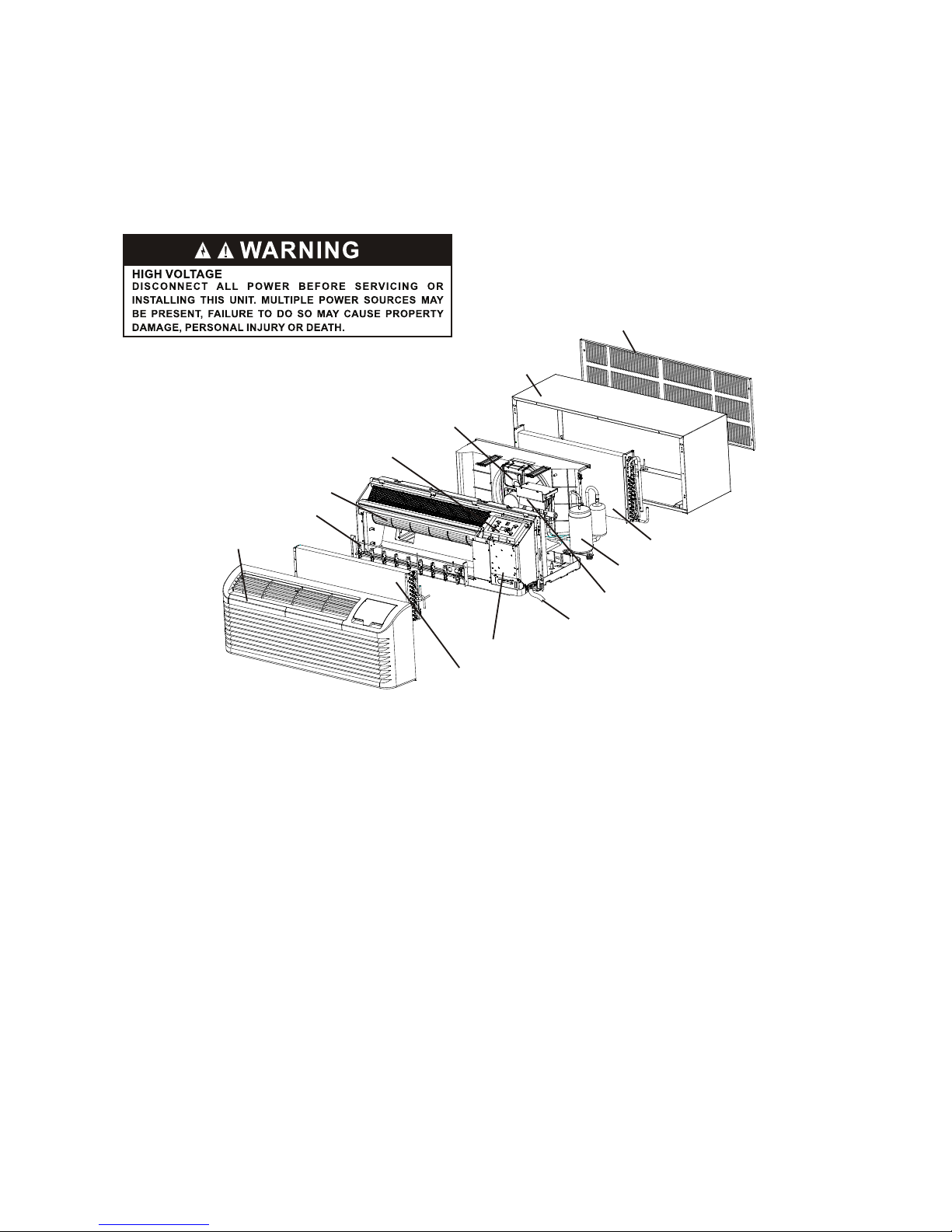
Wall sleeve
Outdoor coil
Outdoor grille
Front and discharge grille
Electric heater
Indoor Fan
Display Module
Outdoor Fan
Inverter compressor
Power cord coverplate(not show)
Electronic control module assembly
Control box
Indoor coil
- 4 -
INSTALLATION INSTRUCTIONS
To ensur e that the unit oper ates safe ly and effici ently, it must be i nstalled, oper ated and maintaine d accordi ng
to these inst allation and operating instr uctions and all local codes and ordina nces or, in their ab sence , with the
lates t ed ition of the Na tional Elect ric Code. The prop er installat ion of this unit is des cribe d in the following
secti ons. Fo llowing th e steps in the o rder pr esented sh ould ensure prope r installa tion.
 Loading...