

Perfect Aire 2PTC12A-3.0, 2PTH15A-5.0 User Manual
FOR MODELS:
2PTC12A-3.0
2PTH15A-5.0
Before using your air conditioner please
read this manual carefully and keep it for
future reference, along with your receipt.
USER MANUAL
PACKAGED TERMINAL
AIR CONDITIONER
CONTENTS
UNIT FEATURES 2
INSTALLATION INSTRUCTION
WIRING
6
MAINTENANCE AND CLEANING
9
NORMAL OPERATING SOUNDS AND CONDITION
11
DIAGNOSTIC CODES
11
… …………………………………………
… …………………………4
… … …
… ……………… ……
………
… …………………………………
… ……… ………………………………………
OPERATING INSTRUCTIONS(ACCESSORY OPTIONAL)
7
-1-
IMPORTANT NOTE TO THE SERVICER
Read this manual and familiarize yourself with the specific
items which must be adhered to before attempting to
service this unit. The precautions listed in this Installation
Manual are intended as supplemental to existing
practices. However, if there is a direct conflict between
existing practices and the content of this manual, the
precautions listed here take precedence.
RECOGNIZE THIS SYMBOL
AS A SAFETY PRECAUTION
THE MANUFACTURER WILL NOT BE RESPONSIBLE FOR ANY
INJURY OR PROPERTY, DAMAGE ARISING FROM IMPROPER
SERVICE OR SERVICE PROCEDURES. IF YOU INSTALL OR
PER FO RM S ER VI CE O N T HI S UNI T, YOU A SS UM E
RESPONSIBILITY FOR ANY PERSONAL INJURY OR PROPERTY
DAM AGE WHICH M AY RES ULT, MANY JURISDICTIONS
REQUIRE A LICENSE TO INSTALL OR SERVICE HEATING AND
AIR CONDITIONING EQUIPMENT.
WARNING
IMPORTANT NOTES:
Before using this manual, check the serial plate for proper
model identification.
The installation and servicing of this equipment must be
performed by qualified, experienced technicians only.
Due to policy of continual product improvement, the right is
reserved to change specifications and design without
notice.
IMPORTANT NOTE TO THE OWNER
This manual is to be used by qualified, professionally trained
HVAC technicians only. The manufacturer does not assume
any responsibility for property damage or personal injury for
improper service procedures or services performed by an
unqualified Person.
THE FOLLOWING WARNINGS ARE
VERY IMPORTANT FOR SAFETY.
PLEASE READ THEM CAREFULLY
BEFORE INSTALLATION!
1. The air conditioner must be installed by
certified installer.
2. Check whether there is grounding wire
in the power supply system before
installation. If not, installers should refuse
installing and explain the safety principle to
users.
3. To avoid electric shock or even death,
the socket or terminal blocks for power
supply to the air conditioner (include
277V and 115V and 208~230V series
and the units that have LCDI power
cord) must connect a Ground Fault Circuit
Interrupter.
4. During installation, the wire
connection must strictly follow the rule
zero line and fire line of unit should
be connected to the zero line and fire line
in the power system. The connection
in reverse is forbidden. Please be sure
the ground wire is firmly connected
otherwise it is possible to result in the
electrical shock or death.
WARNING
HIGH VOLTAGE
DI SCONNECT ALL P OW ER BE FO RE S ERV ICING O R
INSTALLING THIS UNIT. MULTIPLE POWER SOURCES MAY
BE PRESENT, FAILURE TO DO SO MAY CAUSE PROPERTY
DAMAGE, PERSONAL INJURY OR DEATH.
High Pressure Protection: The unit will shut off
automatically when the pressure in the system is over
638 psi and within 10 minutes, after the compressor
turns off, the unit will restart when the pressure turns
back below 551 psi. This protection can effectively
avoid the burst and leakage of pipes, lessen the
system failures and prolong the service life.
Failure Tolerance: If the unit is in protection mode
less than 4 times in one hour, the accumulation times
will reset to avoid system failure. Only when the unit
enters protection mode more than 4 times in one hour,
the system will fail to restart automatically and need
manual restart.
Standard Physical Dimensions:
42" wide x 16" high x 13-3/4" deep
Replacement of older units is made easy.
Weather- Protected Electrical Components: Vital
electrical components are protected from the weather
by locating them on the indoor side of the weather
barrier.
Highly Featured Microprocessor Controls:
Microprocessor controls are programmed to the
interface with temperature sensors to maximize
comfort conditions for the room's occupant and
provide outstanding features.
Thermistors are used to sense small changes in
temperature to give excellent room control and allow
the microprocessor to monitor and react to changing
conditions.
Automatic Emergency Heat on Heat Pump Units:
Automatically uses electric resistance heat if the heat
pump fails.
High-Temperature Heat Pump Operation
Protection: Automatically protects the compressor if
heat pump is operated with high indoor coil
temperatures. Power to the outdoor fan and the
compressor are turned off if the indoor coil gets too
hot during heat pump operation to prevent damage to
the compressor.
UNIT FEATURES
This unit has many features which are different than
those found on conventional PTAC units. The servicer
must be familiar with these features in order to properly
handle the following:
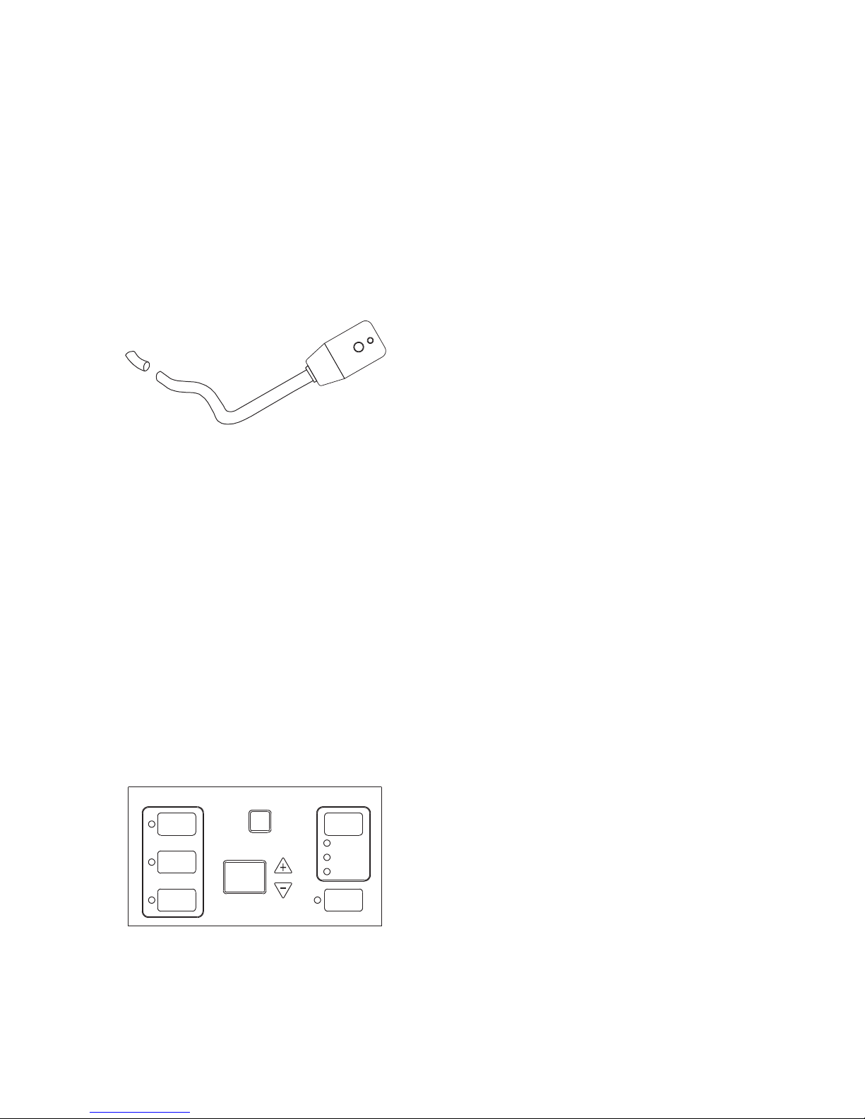
LCDI Cords: Underwriters Laboratories and the
National Electric Code (NEC) require power cords
that sense current leakage and can open the
electrical circuit to the unit on units rated at 250 volts
or less. In the event that unit does not operate, check
the reset button located on or near the head of the
power cord as part of the normal troubleshooting
procedure.
LCDI power Co rd
Automatic 3-minute compressor lockout: After
the compressor cycles off, it will not restart for three
minutes.
Random restart delay: To help eliminate power
surges after a power outage, the unit is equipped with
a two to four minute random restart delay feature.
Whenever the unit is plugged in with the master
switch turned on and the mode switch set in the cool
or heat mode, a random restart will occur. A random
restart condition can be avoided by setting the mode
switch in the fan only or off position before applying
power to the unit.
Indication LEDs: The control panel has LEDs that
correspond to fan operation and to indicate unit
status. The LEDs next to the selections
ON/OFF, FAN, COOL, and HEAT indicate the
operation.
-2-
HEAT
COO L
FAN
ON/O FF
AUT O
LOW
HIG H
SPEE D
FAN
Fan Motors Permanently Lubricated: All units
have two fan motors for quiet operation and maximum
operating efficiency.
Motors are permanently lubricated to reduce
maintenance and completely enclosed to keep dirt
and water out of the motor windings.
Indoor Fan Speed Selections LOW/HIGH: Unit may
be operated in low fan speed or high fan speed. Some
speeds may not be available based on unit capacities.
Rotary Compressor: Smoother operation for quiet,
dependable service and high efficiency.
Indoor Coil Frost Control: Prevents indoor coil from
freezing. Frost can form on the indoor coil when the unit
is operated in cooling when the outdoor temperature
is low. The unit automatically shuts the compressor off
until the indoor coil temperature warms to the point.
UNIT ACCESSORIES
This unit is designed for through-the-wall installation in
new or existing buildings. To complete the installation
of this PTAC, an insulated wall sleeve and an outdoor
grille (either the stamped aluminum grille, or the
architectural grille ) are required.
The chassis and the cabinet front are shipped in one
carton. Optional accessories to complete a particular
installation are the following:
OPTIONAL ACCESSORIES
• Power switch Kit
• Wall Sleeve Kit
• Key Lock Kit • Drain Kit
•
Filter Kit • Hard Wire Kit
• Wire Harness Kit • Architectural Grille Kit
• Stamped Louver
Kit • LCDI Power Cord
• Wireless IR
Antenna • Wireless IR
Thermostat
• Electric
And Non Electric Sub Base Kit
• IR REMOTE CONTROLLER
NOTE: Consu lt sales litera ture f or the app ropri ate
voltage and amperage selections, if appl icabl e.
-3-
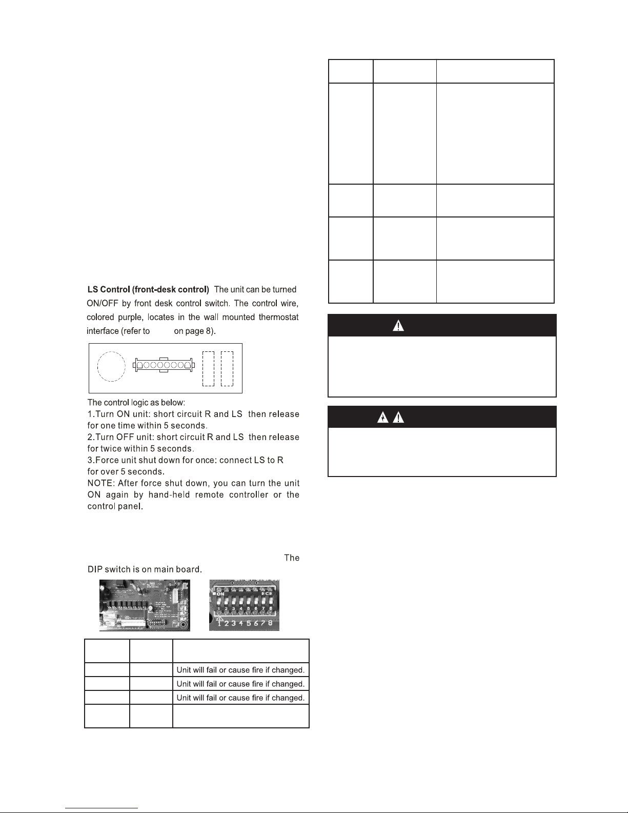
R LS GH B Y W GL C
WALL MOUNTED THERMOSTAT INTERFACE
DIP
Switches
Function Description
ON - When the unit is connected to the power supply, and
the room temperature is lower
than 10°C/50°F for 3 min., the
unit will start heating automatically no matter the mode. Only
when the room temperature
reaches 13°C/55°F will heating stop. (Only for units with
heat pump)
5 Auto Heating
6
Electric Power
ON - Once the power is On
the unit will run the pervious
settings.
off Memory
Fan for Heating ON - Enables the fan to run
continuously when heating.
Default setting is cycling fan in
heating mode.
7
Continuosuly
(CON)/ Cycle
(CYC)
Fan for Cooling ON - Enables the fan to cycle
when cooling. Default setting
is continuous fan in cooling
mode.
8
Cycle (CYC)/
Continuosuly
(CON)
DIP
Switches
Function Description
1 Reserved
2 Reserved
3 Reserved
4
Heating ON - Heat pump to be priority
OFF - Electric Heat to be priorityPriority
Special Control Functions for DIP Switches:
Fig.9
WARNING
Before service, you must disconnect the power cord to
avoid electric shock! Forbid to reprogram DIP switches
NO.1 and No. 3, otherwise the unit will fall into wrong
control or even cause fire! After changing the DIP switch,
power the unit on again; the new function will be activated.
WARNING
HIGH VOLTAGE
DISC ONNE CT A LL P OWER BE FORE SER VI CING O R
INSTALLING THIS UNIT. M ULTIPLE POWER SOURCES MAY
BE PRESENT, FAILURE TO DO SO MAY CAUSE PROPERTY
DAMAGE, PERSONAL INJURY OR DEATH.
:
-4-
INSTALLATION INSTRUCTIONS
To ensure that the unit operates saf ely an d efficie ntly, it must be inst alled , oper ated and maintained a ccord ing
to these installation and operating instructions and all local cod es a nd o rdina nces or, in t heir abse nce, with the
latest edition of the National E lectric C ode. Th e pr oper installat ion of this unit is described in the following
sections. Following the steps in th e order p resen ted sho uld ens ure pro per ins talla tion.
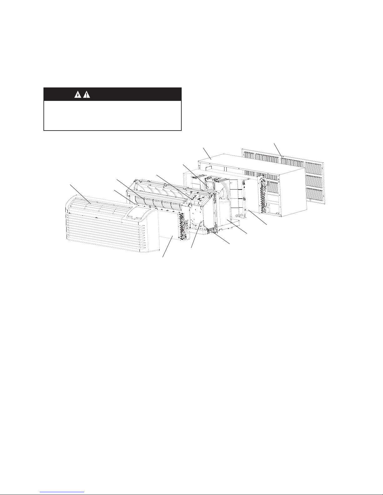
Front and discharge grille
Electric heater
Indoor
Fan
Display Module
Outdoor Fan
Wall sleeve
Indoor coil
Control box
Power cord cover
plate (not shown)
Rotary compressor
Outdoor coil
Outdoor
grille
WARNING
HIGH VOLTAGE
DISCONNECT ALL POWER BEFORE SER VICING OR
INSTALLING THIS UNIT. MULTIPLE POWER SOURCES MAY
BE PRESENT, FAILURE TO D O SO MAY CAUSE PROPERTY
DAMAGE, PERSONAL INJURY OR DEATH.
 Loading...