

Perfect Aire 2PAMSH36-MZ04, 2PAMSH27-MZ03, 2PAMSH18-MZ02, 2PAMSH48-MZ05 Installation Manual

Accessories .................................................... 04
Safety Precautions .....................................05
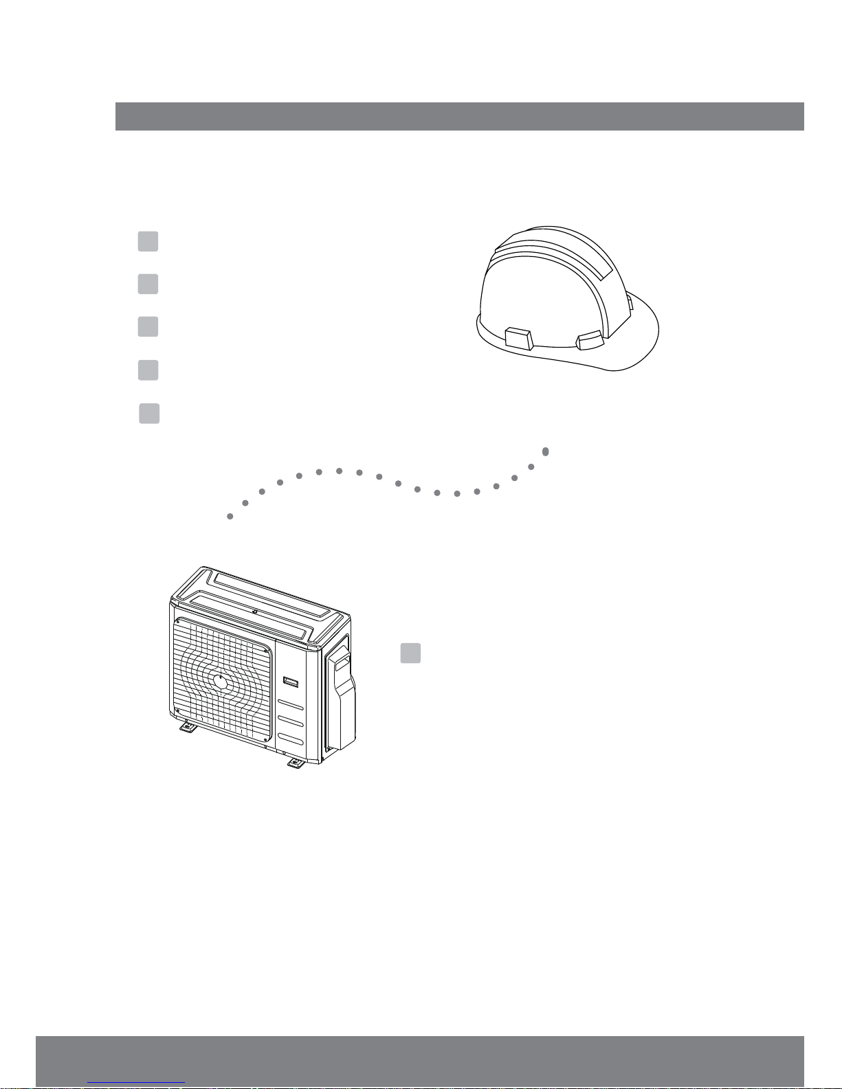
Outdoor Unit Installation ......................... 09
a. Outdoor Unit Installation Instructions..... 09
b. Drain Joint Installation................................ 11
c. Notes on Drilling Hole in Wall................... 11
d.
Selecting a 24K Indoor Unit........................11
Table of Contents
Installation Manual
Installation Diagram
................................07
Installation Overview ...............................06
1
2
6
3
4
Specifications
..............................................08
5
Page 3
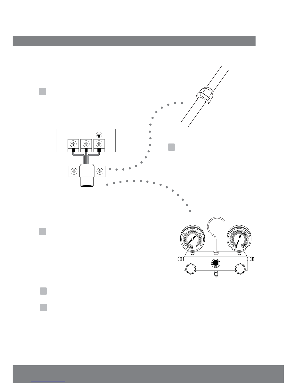
Refrigerant Piping Connection ...............12
Wiring ................................................. 14
a. Outdoor Unit Wiring................... 14
b.
Air Evacuation
.......................................... 20
a. Evacuation Instructions.........................20
b. Note on Adding Refrigerant ............... 21
Test Run.......................................................22
Function of Automatic Wiring/Piping Correction......23
MC MC
7
8
9
10
11
LN
The design and specifications are subject to change without prior notice for productod
improvement. Consult with the sales agency or manufacturer for details.
Wiring Diagram
............................16
Page 4
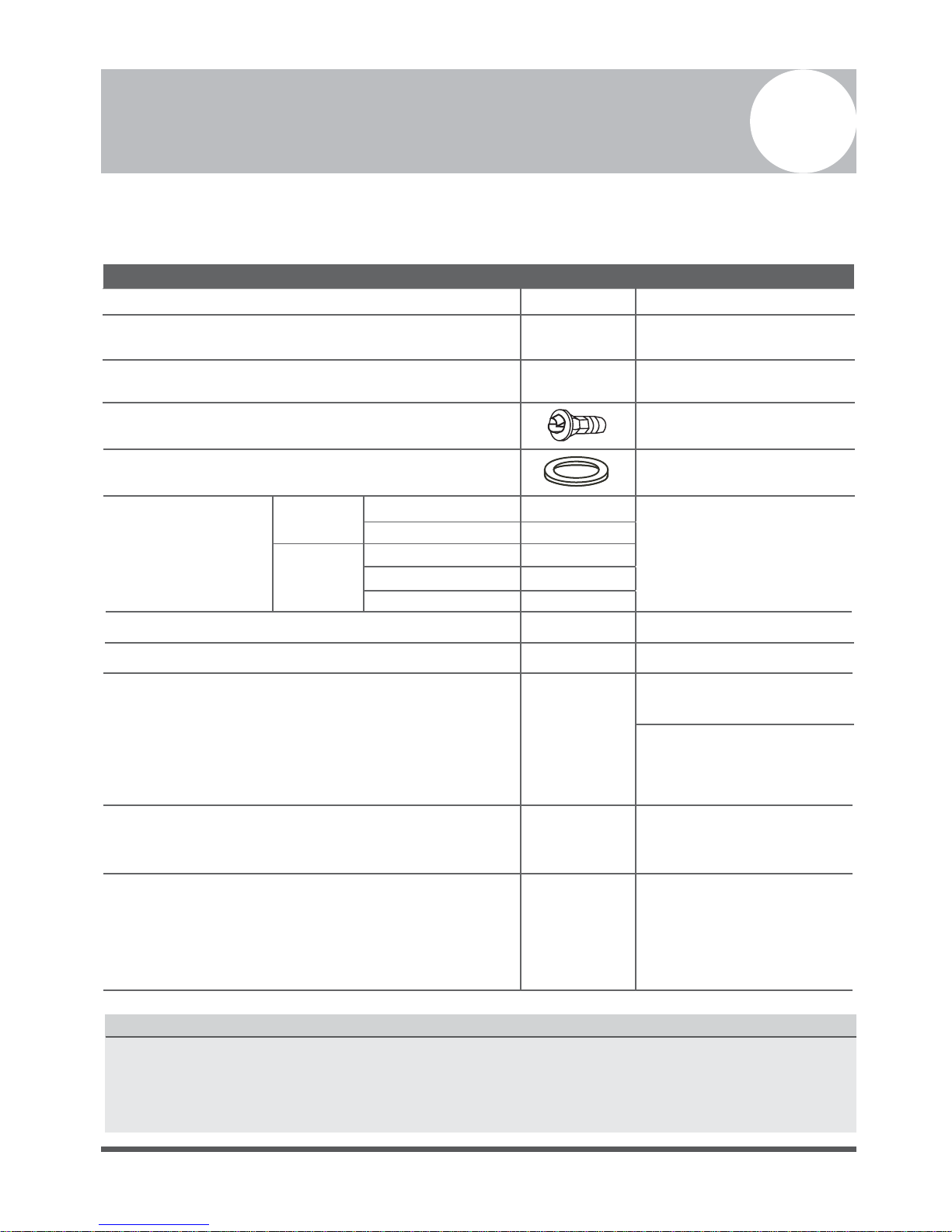
Accessories
1
The air conditioning system comes with the following accessories. Use all of the installation parts and
accessories to install the air conditioner. Improper installation may result in water leakage, electrical
shock and fire, or equipment failure and void warranty.
Liquid side
Ø1/4”(Ø6.35mm)
Ø3/8”(Ø9.52mm)
Ø3/8”(Ø9.52mm)
Ø1/2”(Ø12.7mm)
Ø5/8”(Ø15.9mm)
Gas side
Name Shape Quantity
Installation plate
1
Plastic expansion sheath
5-8
Self-Tapping Screw A ST3.9X25
5-8
Connecting
pipe
assembly
1
Drain joint (some models)
1
Seal ring (some models)
Parts you must purchase.
Consult a technician for
the proper size.
1
1
Owner’s manual
Installation manual
Optional part
(one piece/one indoor unit)
Optional part
(1-5 pieces for outdoor
unit, depending on models)
Flare nut connector
s (packed with the indoor or
outdoor unit, depending on models)
NOTE: Pipe size may differ from unit to unit. To
meet different pipe size requirements, the pipe
connections may need a flare nut connector
installed on the outdoor unit .
Optional part
(one piece/one cable)
Magnetic ring
(Secure
on the connective cable between the
indoor unit and outdoor unit after installation.)
1
Cord protection rubber ring
(If the cord clamp cannot fasten on a small cord, use
the cord protection rubber ring [supplied with
accessories] to wrap around the cord. Secure in
place with the cord clamp.)
(depending on models)
(depending on models)
(on some models)
Optional Accessories
There are two types of remote controls: wired and wireless.
Select a remote control based on customer preferences and requirements and install in an
appropriate place.
Refer to catalogs and technical literature for guidance on selection of a suitable remote control.
Page 5
Safety Precautions
2
Read Safety Precautions Before Installation
Incorrect installation due to ignoring instructions can cause serious damage or injury
and void warranty. The seriousness of potential damage or injuries is classified as either a
WARNING or CAUTION.
WARNING
• Carefully read the Safety Precautions before installation.
• In certain environments, such as kitchens, server rooms, etc., the use of specially designed air-
conditioning units is highly recommended.
• Only
authorized, trained and certified technicians should install, repair and service
this air conditioning unit.
Improper installation may result in electrical shock, short circuit, leaks, fire or other damage to
the equipment and personal property.
• Strictly follow the installation instructions set forth in this manual.
Improper installation may result in electrical shock, short circuit, leaks, fire or other damage to
the equipment and void warranty.
• Before you install the unit, consider strong winds, heavy rain, snow or other conditions that
might affect your unit and locate it accordingly. Failure to do so could cause the equipment to fail.
• After installation, ensure there are no refrigerant leaks and that the unit is operating properly.
Refrigerant is both toxic and flammable and poses a serious health and safety risk.
Note about Fluorinated Gasses
1. This air-conditioning unit contains fluorinated gasses. For specific information on the type of gas
and the amount, please refer to the relevant label on the unit itself.
2. Installation, service, maintenance and repair of this unit must be performed by an authorized,
trained and certified technician.
3. Systen decommissioning and recycling must be performed by an authorized, trained and
certified technician.
4. If the system has a leak-detection system installed, it must be checked for leaks at least every 12
months.
5.
When the unit is checked for leaks, proper record-keeping of all checks is strongly recommended.
Failure to observe a warning may result in death. The unit must be installed in
accordance with national, regional or local regulations.
Failure to observe a caution may result in injury or equipment damage.
WARNING
CAUTION
Page 6
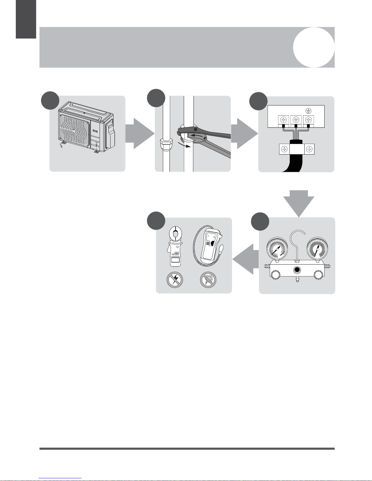
Installation Overview
3
Unit Installation
Overview
LN
1
2
3
MC MC
4
5
INSTALLATION ORDER
Install the outdoor unit
(Page 9)
Evacuate the refrigeration
system
(Page 20)
Connect the wires
(Page 14)
Connect the refrigerant pipes
(Page 12)
Perform a test run
(Page 22)
Page 7
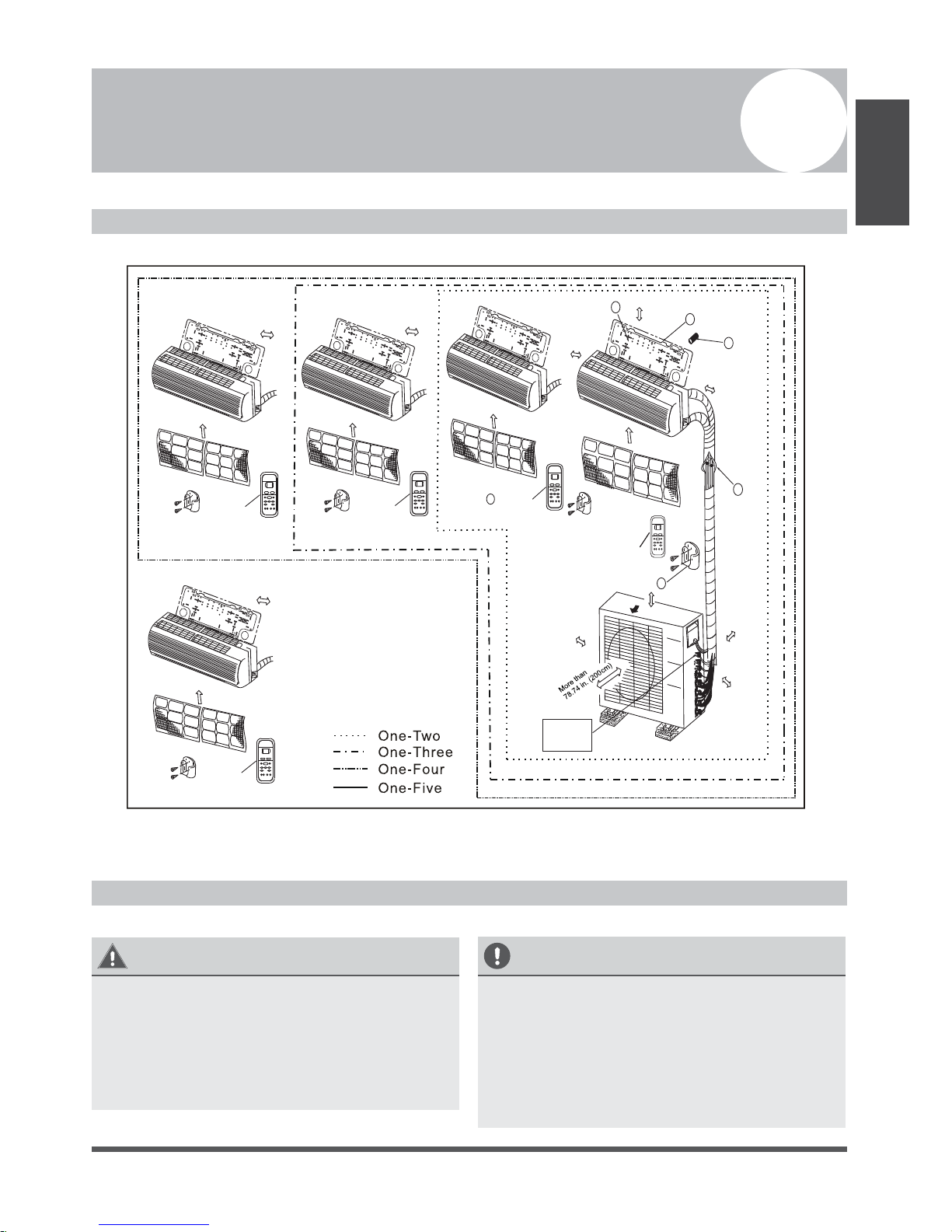
Installation Diagram
4
Installation Diagram
Fig. 4.1
Safety Precautions
CAUTION
• This illustration is for demonstration
purposes only.
The actual shape of your air condtioner may
be slightly different.
Copper lines must be independently
insulated.
•
CAUTION
• To prevent wall damage, use a stud finder
to locate studs.
A minimum pipe run of 10ft (3m) is required
to minimize vibration & excessive noise.
Two of the A, B, and C air circulation
pathways must be free from obstructions at
all times.
•
•
Installation
Diagram
Air f ilter
Air f ilter
2
More th an 5.91 in. (15 cm)
1
3
4
5
Remote
Remote
Remote
contr ol
control
control
Remote
control
6
Air o ut
A
B
C
Loop a
connectiv e
cable
Remote
control
Air f ilter
Air f ilter
Air f ilter
Mo
i
r
e
(1
th
0
a
c
n
m)
3.94 n.
More than 4.72 in.
More than 4.72 in.
(12cm)
(12cm)
More than 4.72 in.
(12cm)
More than 4.72 in.
(12cm)
More than 4.72 in.
(12cm)
More
11.81
than
(30cm)
in.
Mor
(
e
23.62
than
60cm
in
)
More than 2 ft
(60cm)
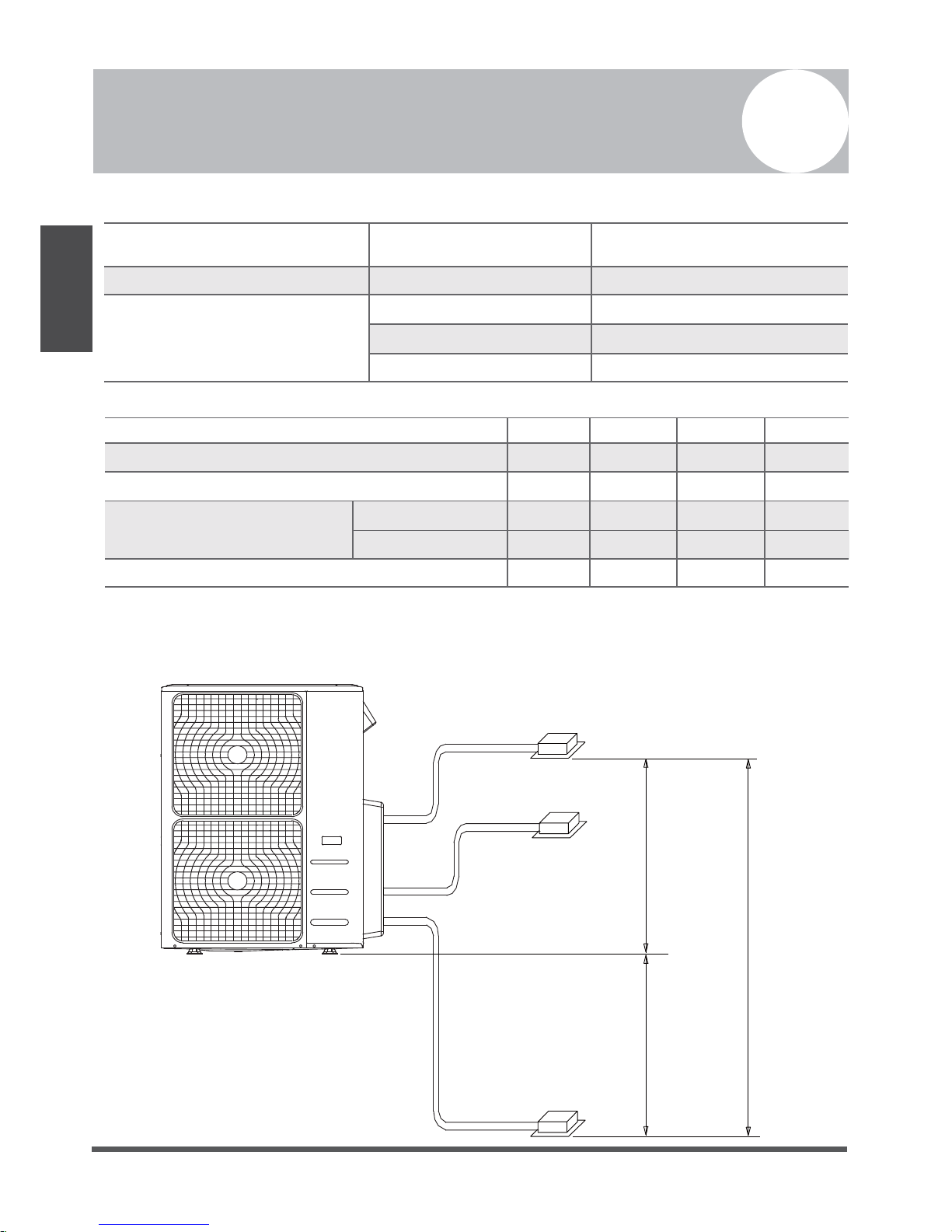
Table 5.1
Table 5.2 - units of measurement in this table are in m/ft.
(example: 30m/98.4 ft.)
Page 8
Specifications
5
Outdoor Unit
Specifications
Number of units that can be used
together
Connected units
1-5 units
Compressor stop/start frequency Stop time 3 min or more
Voltage fluctuation within ±10% of rated voltage
Power source voltage
Voltage drop during start within ±15% of rated voltage
Interval unbalance within ±3% of rated voltage
1 drive 2 1 drive 3
Max. length for all connected units
30/98.4 45/147.6
Max. length for one indoor unit 25/82 30/98.4
Max
. height differential between
indoor units and outdoor unit
OU higher than IU
15/49 15/49
OU lower than IU 15/49 15/49
Max. height differential between indoor units
10/32.8 10/32.8
1 drive 4 1 drive 5
60/196.8 75/246
35/114.8 35/114.8
15/49 15/49
15/49 15/49
10/32.8 10/32.8
10m(32.8ft)
When installing multiple indoor units with a single outdoor unit, ensure that the length of the
refrigerant pipe and the drop height between the indoor and outdoor units meet the requirements
illustrated in the following diagram and table above.
Indoor unit
Indoor unit
Indoor unit
Outdoor unit
15m(49ft)
15m(49ft)
Max.Height difference
 Loading...