

Perfect Aire 2PAMSH18-MZ02, 2PAMSH27-MZ03, 2PAMSH36-MZ04, 2PAMSH48-MZ05 User Manual


CAUTION
Table of Contents
User Manual
Safety Precautions
Warning .......................................................................................................................... 1
Caution ........................................................................................................................... 2
Identification of Parts
Indoor unit ................................................................................................................ 3–13
Outdoor unit.............................................................................................................. 3–13
Display window......................................................................................................... 3–13
Operating Instructions
Operating temperature ................................................................................................. 14
Manual operation.......................................................................................................... 14
Airflow direction control .......................................................................................... 15–16
How the air conditioner works ...................................................................................... 17
Care and Maintenance
Wall-mounted units................................................................................................. 18–19
Cassette type ............................................................................................................... 20
Ducted types .......................................................................................................... 20–21
Maintenance.................................................................................................................22
Operation tips ......................................................................................................... 22–23
Troubleshooting Tips
Troubleshooting tips ..................................................................................................... 24
• Contact an authorized service technician or certified HVAC contractor for installation of
this unit.
• Contact an authorized service technician or certified HVAC contractor for repair or
maintenance of this unit.
• This appliance is not intended for use by persons (including children) with reduced physical,
sensory or mental capabilities, or lack of experience and knowledge, unless they have been
given supervision or instruction concerning use of the appliance by persons responsible for
their safety.
• Young children should be supervised to ensure that they do not play with the air conditioner.
• Installation work must be performed in accordance with national or local wiring standards by
authorized personnel only.
To prevent injury to the user or other people and property damage, the following instructions must
be followed. Incorrect operation due to ignoring or not following installation and usage instructions
may cause harm or damage. The seriousness is classified by the following indications:
Page 1
Safety Precautions
This symbol indicates the possibility of death or serious injury.
Meanings of symbols used in this manual are as shown below.
Be sure to follow these instructions.
CAUTION
This symbol indicates the possibility of injury or damage to property.
WARNING
Strictly prohibited.
• NEVER splice any electrical
connection. A poor electrical
connection, poor insulation or voltage
which is higher than permitted can
cause fire.
• Do not expose your body directly to the
cool air for prolonged periods of time.
• Never poke fingers, sticks or other
objects in the air inlet and outlet vents.
• Never attempt to repair, relocate, or
modify the air conditioner yourself.
Always contact your qualified service
provider if required.
• Do not operate your air conditioner in a
wet environment such as a bathroom
or laundry room.
• Contact an authorized service
technician or certified HVAC contractor
for installation of this unit.
• Contact an authorized service
technician or certified HVAC contractor
for repair or maintenance of this unit.
• In the event of any abnormality such as
a burning smell, completely power off
the device. Contact your qualified
service provider.
• Completely power off the system
before attempting to clean it.
• Use specified wiring.
• This air conditioner is not intended for
use by persons (including children)
with reduced physical, sensory or
mental capabilities, or lack of
experience and knowledge, unless
they have been given supervision or
instruction concerning use of the air
conditioner by a person responsible for
their safety.
• Children should be supervised to
ensure that they do not play with the
air conditioner.
Page 2
Safety Precautions
• Never operate any controls with wet
hands. Doing so may cause an electric
shock.
• Never use the device for any other
purpose than the intended use.
• Never place food, precision instruments,
plants, animals, paint, etc. on the unit.
• Do not expose plants or animals directly
to the air flow of the unit.
• Never clean the air conditioner with
water.
• Never use combustible cleaning agents
as these could cause a fire or
deformation.
• Never place any burning objects close to
the device if they could be directly
affected by the emitted air.
• Never step onto the outdoor unit and
never place anything on it.
• Never use an unsteady or rusty base to
support outdoor unit.
• Never install the air conditioner in places
where combustible gas can be emitted.
Emitted gas may collect and cause an
explosion.
• Never allow the air conditioner to run for
too long with the doors or windows open,
or if the humidity is very high.
• If the air conditioner is to be used in
conjunction with other heaters, the air
should be refreshed perioically; otherwise
there is a risk of lack of oxygen.
• Always completely power off the unit if it
is not going to be used for an extended
period of time. Collecting dust can cause
fire.
• Always completely power off the air
conditioner during a storm. Otherwise,
electrical parts may get damaged.
• Check that the drainage line is correctly
connected. If not, water will escape.
• Check that the condensate water can run
off unhindered. It may cause water
damage if the condensate water cannot
drain away properly.
• The air conditioner must be electrically
grounded in accordance with the local
codes.
• For electrical safety & maintenance
purposes we recommend that you install
a seperate circuit-breaker/disconnect
switch and surge protection.
NOTE:
A guide to using the remote control
is included in this literature package.
Page 3
1
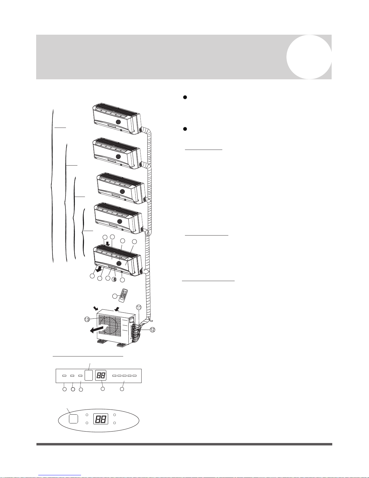
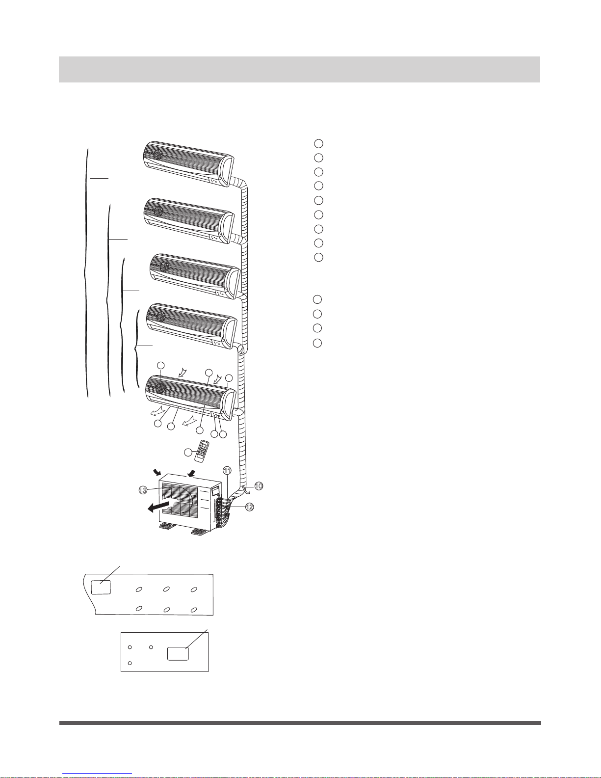
Identification of Parts
Indoor unit
Outdoor unit
Indoor unit
IMPORTANT:
For multi-split type air conditioners, one outdoor
unit can match different types of indoor units.
All of the pictures in this manual are for explan ation purposes only. Your air conditioner may be
slightly different. The actual shape shall prevail.
The following pages introduce several kinds of
indoor units matching with the outdoor units.
LED Display panel
AUTO indication lamp
Lights up during the Auto operation.
OPERATION indication lamp
This indicator appears only when the compressor
is in operation and indicates the current operating
frequency.
TIMER indication lamp
Lights up during Timer operation.
DEFROST indication lamp
(For Cooling & Heating models only):
Lights up when the air conditioner starts
defrosting automatically or when the warm air
control feature is activated in heating operation.
1. Front panel
2. Top air intake
3. Air filter (Inside)
4. Air outlet
5. Horizontal air flow louver
6. Vertical air flow louver (Internal)
7. Display panel
8. LED display window
9. Remote control
10. Manual control button (Behind the front panel)
11. Refrigerant connecting pipe, drain hose and
electric wiring
12. Stop valve
13. Air outlet
DIGITAL DISPLAY indication lamp
Displays the current setting t
emperature. When
the air conditioner is in FAN operation, it displays
the actual room temperature. It also will display
mulfunction and protection codes.
Display panel
Signal receptor
AUT O
DEF ROST
OPE RATION
TIM ER
Signal receptor
1
22
3
4
5
AUTO TI MER
DEF.
FRE QUENC Y
(1)
(2)
Outdoor unit
One-twi n
One-thr ee
One-fou r
One-fiv e
9
11
12
13
4
3
5
2
6
1
10
7
8
Page 4
Indoor unit
Outdoor unit
10
Indoor unit
Display Panel
Outdoor unit
Air outlet
Air inlet
3
8
7
4
5
6
2
1
One-twi n
One-thr ee
One-fou r
One-fiv e
9
11
12
13
Front panel frame
Front panel
Air filter
Horizontal air flow grille
Vertical air flow louver
Room temperature sensor
Display panel
Infrared signal receiver
Remote control
Drain hose, refrigerant connecting pipe
Connective cable
Stop valve
Fan hood
1
3
4
5
6
7
8
9
10
11
12
2
13
DISPLAY PANEL
OPERATION indicator:
The indicator flashes once every second
after power is on and illuminates when the
air conditioner is in operation.
TIMER indicator:
The indicator illuminates when TIMER is set
ON.
PRE-DEF. Indicator (For cooling& heating
model only):
This indicator illuminates when the air
conditioner starts defrosting automatically or
when the Anti-cold air function is activated in
heating operation.
AUTO indicator:
This indicator flashes when the air
conditioner is in AUTO operation.
TIMER OPERATION
PRE-DEF
Infrared signal receptor
Infrared signal receptor
OPERATION
TIMER
PRE-DEF
AUTO
(1)
(2)
Identification of Parts (continued)
Page 5
Identification of Parts (continued)
Indoor unit
Outdoor unit
LED Displ ay window
Identification of parts
Indoor unit
Front panel frame
Front panel
Air filter
Horizontal air flow grille
Vertical air flow louver
Room temperature sensor
Display panel
Remote control
Drain hose, refrigerant connecting pipe
Connective cable
Stop valve
Fan hood
1
3
4
5
6
7
8
9
10
11
12
2
LED DISPLAY WINDOW
a u to
1
22
3
4
5
1
22
3
4
5
AUTO indication lamp
Lights up during the Auto operation.
OPERATION indication lamp
This indicator appears only when the
compressor is in operation and indicates the
current operating frequency.
TIMER indication lamp
Lights up during Timer operation.
DEFROST indication lamp
(For Cooling & Heating models only):
Lights up when the air conditioner starts
defrosting automatically or when the warm air
control feature is activated in heating operation.
DIGITAL DISPLAY indication lamp
Displays the current setting temperature. Only
when the ai
r conditioner is in FAN operation, it
displays the actual room temperature. And
displays the malfunction code or protection code.
(1)
(2)
9
Outdoor unit
One-twi n
One-thr ee
One-fou r
One-fiv e
10
11
12
Air outlet
Air inlet
8
4
3
5
2
6
1
7
Page 6
Indoor unit
Outdoor unit
Indoor unit
Outdoor unit
Air outlet
One-twi n
One-thr ee
One-fou r
One-fiv e
9
10. Drain hose, refrigerant connecting pipe
11. Connective cable
12. Stop valve
13. Fan hood
10
11
12
13
Indoor unit
6
5
7
8
1
2
3
4
Air outle t
Air inlet
1. Panel frame
2. Rear air intake grille
3. Front panel
4. Air filter (behind)
5. Horizontal louver
6. LCD display window
7. Vertical louver
8. Manual control button (behind)
9.
Remote control holder
Identification of Parts (continued)
 Loading...