

Perfect Aire 1PAMSHQCW12-15 Installation Manual
Your Source for Home Comfort
12,000 BTU / 15 SEER QUICK CONNECT
DUCTLESS MINI-SPLIT
With 11,500 BTU Heat Pump
INSTALLATION
MANUAL
FOR MODELS:
1PAMSHQCW12-15
Indoor Wall Unit
1PAMSHQCW12-15
Outdoor Condenser
Before using your air conditioner,
please read this manual carefully
and keep it for future reference,
along with your receipt.

Contents
This manual provides the information needed for proper use and maintenance of this air conditioner.
Basic preventative care can help extend the life of this unit. The “Troubleshooting Tips” section in this
manual contains a chart with solutions to the most common problems. Referring to this section may
save time and prevent the need for a service call in the event of a problem.
Safety Precautions
Warning .......................................................................................................................................2
Caution ........................................................................................................................................2
Installation Instructions
Selecting installation location ......................................................................................................3
Accessories .................................................................................................................................4
Indoor unit installation..................................................................................................................8
Outdoor unit installation ...............................................................................................................9
Refrigerant Pipe Connection
Refrigerant pipe connection.......................................................................................................10
Electrical Work
Electrical work ...........................................................................................................................12
Test Running
Test running ...............................................................................................................................14
CAUTION
!
• Contact a trained service technician for repair or maintenance of this unit.
• Contact an installer for installation of this unit if necessary.
• The air conditioner is not intended for use by young children without supervision. Young
children should be supervised to ensure that they do not play with the air conditioner.
• Disabled persons may require assistance with set up.
• If the communication cable is damaged or needs repair, replacement work should be
performed by trained service technician only.
• Installation and repair work must be performed in accordance with the national wiring
standards by a trained service technician only.
-1-
Safety Precautions
To prevent injury to the user or other people and property damage, the following instructions must be
followed. Incorrect operation due to ignoring instructions may cause harm or damage.
Failure to adhere to each of the following precautions can lead to results classied as follows:
! !
!
WARNING
CAUTION
This symbol indicates the possibility of death or serious injury.
This symbol indicates the possibility of injury or damage to property.
Meanings of symbols used in this manual are as shown below.
Never do this.
!
• Contact a trained service professional for installation. If installation done by the user is incorrect, it can cause
water leakage, electrical shock or re.
• Install according to these exact installation instructions. If installation is not performed correctly, it can cause
water leakage, electrical shock or re.
• Use the enclosed accessories and parts for installation in order to avoid unit failure, water leakage, electrical
shock or re.
• Install at a location that is strong enough to withstand the weight of the indoor and outdoor units. If the
installation is not properly done or location is not strong enough to hold the units, the set can drop and cause
injury to the unit and persons.
• For electrical work, follow the national wiring standards, regulartions, and these installation instructions. An
independent circuit must be used. If electric circuit capactiy is not enough or the electrical work is defective, it
can cause electrical shock or re.
• Use the specied cable and connect it tightly, clamping the calbe so that no external force will be placed on the
terminal. If connection is not perfect, it can cause the connection to heat up and possibly set re.
• Routing of the wiring must be aproperly arranged so the control board cover is xed properly. If the control
board cover is not xed perfectly, it can cause the connection to heat up, set re, or electrical shock.
• When carrying out piping connection, take care not to let air substances other than the specied refrigerant go
into the refrigeration cycle in order to avoid causing lower capacity, abnormally high pressure in the refrigeration
cycle, explosion and injury.
• Do not modify the length of the power supply cord, do not use extension cord, and do not share the circuit with
other electrical appliances. Doing any of these things can cause re or electrical shock.
WARNING
!
!
Always do this.
CAUTION
!
• This equipment must be grounded and installed with a grounded circuit breaker. Electrical shock could occur if
unit is properly grounded.
• Do not install this unit in a place where leakage orf lammagle gas may occur. A gas leak near the unit can
cause re.
• Carry out drainage piping as mentioned in installation instructions. If drainage is not perfect, water may enter the
room and damage items such as furniture and electronics.
-2-
Installation Instructions
(from the floor)
More than
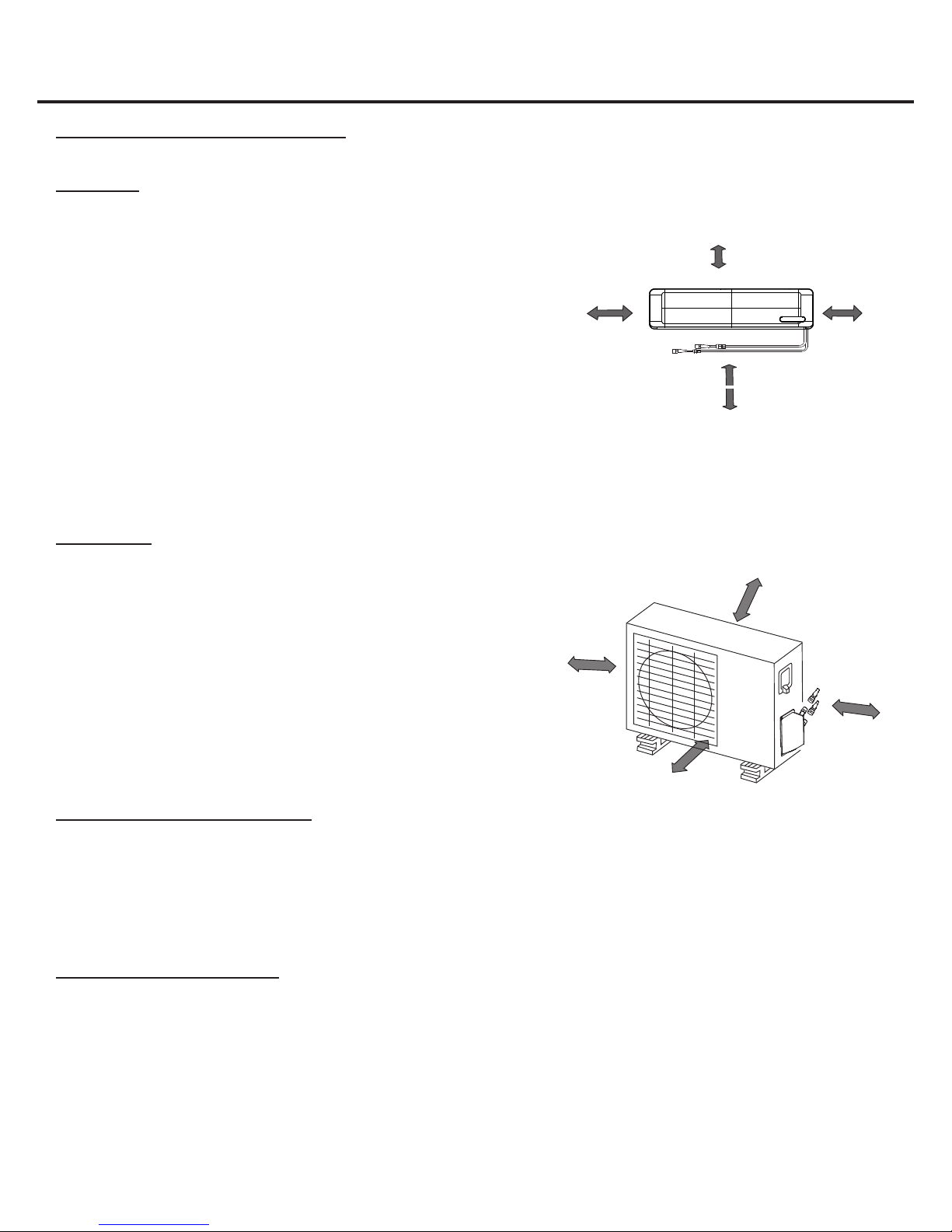
Selecting an installation location
Please read through the following directions completely before installing. When installing, follow these step by step.
Indoor Unit
• Do not expose the indoor unit to heat or steam.
• Select a place where there are no obstacles in front or around the unit.
• Make sure that condensation drainage can be conveniently routed away.
• Do not install near a doorway.
• Ensure that the space on the left and right of the unit is more than
4.75 in. (12 cm).
• Use a stud nder to locate studs to prevent unnecessary damage to
the wall.
• The indoor unit should be installed on the wall at a height of 7.55 ft
(2.3 m) or more from the oor.
• The indoor unit should be installed allowing a minimum clearance of
6 in. (15 cm) from the ceiling.
• Any variations in pipe length may require adjustment to refrigerant charge.
• There should not be any direct sunlight. Sunlight will fade the plastic cabinet and affect its appearance.
Outdoor Unit
• If an awning is built over the outdoor unit to prevent direct sunlight or
rain exposure, make sure that heat radiation from the condenser is
not restricted.
• Ensure that the clearance around the back of the unit is more than
12 in. (30 cm) and left side is more than 12 in. (30 cm). The front of
the unit should have more than 79 in. (200 cm) of clearance and the
connection side (right side) should have more than 24 in. (60 cm)
of clearance.
• Do not place animals and plants in the path of the air inlet or outlet.
• Take the air conditioner weight into account and select a place where
noise, vibration and warm air from the air conditioner will not be an
issue for you and your neighbors.
Outdoor Unit - Rooftop Installation
• If the outdoor unit is installed on a roof, be sure to level the unit.
• Ensure the roof structure and anchoring method are adequate for the unit location.
• Consult local codes regarding rooftop mounting.
• If the outdoor unit is installed on a roof structure or external walls, this may result in excessive noise and vibration, and
may also be classied as a non-serviceable installation.
More than
4.72 in.
(12 cm)
More than
11.81 in.
(30 cm)
More than 78.74 in.
More than 5.9 in. (15 cm)
(to the ceiling)
More than
4.72 in.
(12 cm)
More than 7.55 ft (2.3 m)
Fig. 1
More than 11.81 in. (30 cm)
23.62 in.
(60 cm)
(200 cm)
Fig. 2
Tools Required for Installation
• Level gauge
• Screwdriver
• Electric drill, Hole core drill (3.54 in./90 mm)
• Flaring tool set
• Specied torque wrenches: 1.8kgf.m,
4.2kgf.m, 5.5kgf.m, 6.6kgf.m
(different depending on model no.)
• Spanner (half union)
• Hexagonal wrench
(0.157 in./4 mm)
• Gas-leak detector
• Vacuum pump
• Gauge manifold
-3-
• Users manual
• Thermometer
• Multimeter
• Pipe cutter
• Measuring tape
>4.72 in. (12 cm)
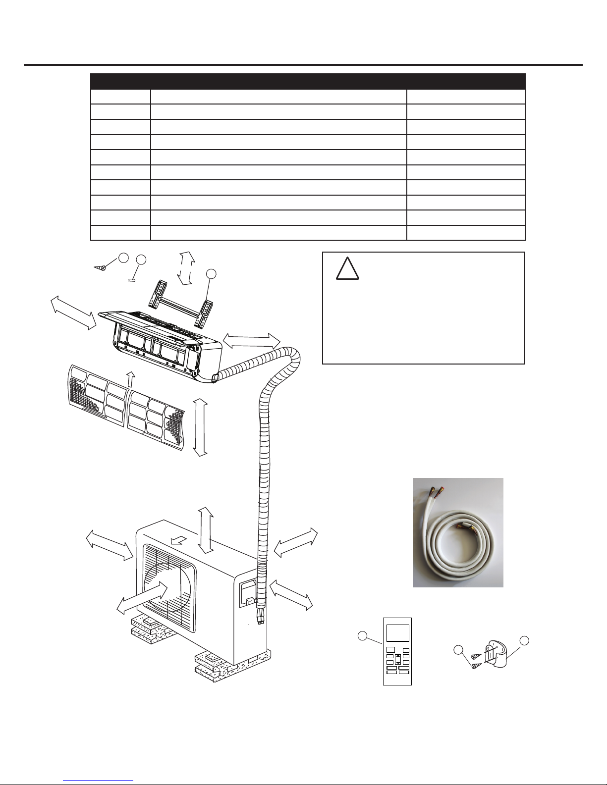
Installation Instructions (continued)
Number Name of Accessory Quantity
1 Installation Plate 1
2 Clip Anchor 5–8
3 Self-tapping Screw A ST3.9X25 5–8 (depends on model)
4 Seal 1
5 Drain Joint 1
6 Remote Control 1
7 Self-tapping Screw B ST2.9X10 (optional) 2
8 Remote Control Holder (optional) 1
9 Quick connecting refrigerant pipe (line set) 1
10 Sound deadening pads
3
2
>15.9 in. (15 cm)
1
(used to wrap up the quick connectors) 2
CAUTION
!
• Use a stud nder to locate studs to
prevent unnecessary damage to the wall.
• Two of the A, B and C directions should
be free from obstructions.
>4.72 in. (12 cm)
• Copper lines must be insulated
independently.
(depends on model)
A
> 11.81 in.
B
Air Filter
Air Outlet
> 78.74 in.
>7.54 ft (2.3 m)
>23.62 in.
> 11.81 in.
>23.62 in.
C
Quick Connecting
Refrigerant Pipe (Line Set)
6
ON/OFF
SHORT
CUT
MODE
TIMER ON
TEMP
TIMER OFF
FAN
SLEEP
SWING DIRECT
TURBO
LED
7
8
NOTE: All the pictures in the manual are for explanation purposes only. The actual shape of the unit you purchased may
be slightly different, but the operations and functions are the same.
NOTE: The parts listed above are included with this unit. Any other required tools/items for installation must be purchased.
-4-
 Loading...