

Perfect Aire 1PAMSCH12, 1PAMSH09-MZW-16, 1PAMSCH18, 1PAMSH18-MZW-16, 1PAMSH18-MZO2-16 Installation Manual
...
Before using your multi-zone inverter mini-split system, please read
this manual carefully and keep it for future reference along with your receipt.
INVERTER MULTI-ZONE HEAT
PUMP MINI-SPLIT SYSTEMS
Please read this installation manual completely
before installing the product.
Replacement and repair work shall be performed
by authorized personnel only.
Installation work must be performed in accordance
with the national wiring standards by authorized
personnel only.
Contact an authorized service technician for
repair, maintenance or installation of this unit.
CONTENTS
SAFETY PRECAUTIONS
Warning ...........................................................................................................................................2
Caution ............................................................................................................................................2
INSTALLATION INSTRUCTIONS
Selecting installation place...............................................................................................................3
Wall-mounted type ...........................................................................................................................3
Accessories .........................................................................................................4
Four-way cassette type ....................................................................................................................9
Outdoor unit installation ..........................................................................................................................15
REFRIGERANT PIPE CONNECTION
Refrigerant pipe connection .............................................................................................................16
ELECTRICAL WORK
Electrical work ................................................................................................................................17
AIR PURGING
Air purging with vacuum pump .........................................................................................................21
Safety and leakage check ................................................................................................................22
TEST RUNNING
Test running ............................................................................................................................................23
TROUBLE SHOOTING TIPS
Trouble shooting tips .....................................................................................................................24
Read This Manual
This manual provides the information needed for proper use and maintenance of this unit.
Basic preventive care can help extend the life of this unit. The “Troubleshooting Tips” contains a chart
with solutions to the most common problems. Referring to this section may save time and prevent
the need for a service call in the event of a problem.
CAUTION
Contact an authorized service technician for repair or maintenance of this unit.
Contact an authorized installer for installation of this unit.
The air conditioner is not intended for use by young children without supervision.
Disabled persons may require assistance with set up.
Young children should be supervised to ensure that they do not play with the air conditioner.
Replacement work shall be performed by authorized personnel only.
Installation work must be performed in accordance with the national wiring standards by authorized
personnel only.
1
SAFETY PRECAUTIONS
Read the following SAFETY PRECAUTIONS carefully before installation.
Electrical work must be installed by a licensed electrician. Be sure to use the correct rating
of the power plug and main circuit for the model to be installed.
Incorrect installation due to ignoring of the instructions will cause harm or damage.
The seriousness is classified by the following indications.
WARNING
CAUTION
This symbol indicates the possibility of death or serious injury.
This symbol indicates the possibility of injury or damage to property.
The items to be followed are classified by the symbols:
Symbol with white background denotes item that is PROHIBITED from doing.
WARNING
1) Engage dealer or specialist for installation. If installation done by the user is defective, it will cause water
leakage, electrical shock or fire.
2) Install according to these installation instructions strictly. If installation is defective, it will cause water
leakage, electrical shock or fire.
3) Use the attached accessories parts and specified parts for installation. Otherwise, it will cause the set to fall,
water leakage, electrical shock or fire.
4) Install at a strong and firm location which is able to withstand the set s weight. If the strength is not enough
or installation is not properly done, the set will drop and cause injury.
5) For electrical work, follow the local national wiring standard, regulation and these installation instructions. An
independent circuit and single outlet must be used. If electrical circuit capacity is not enough or defect found
in electrical work, it will cause electrical shock or fire.
6) Use the specified cable and connect tightly and clamp the cable so that no external force will be acted on
the terminal. If connection or fixing is not proper, it will cause heat-up or fire at the connection.
7) Wiring routing must be properly arranged so that control board cover is fixed properly. If control board cover
is not fixed properly, it will cause heat-up at connection point of terminal, fire or electrical shock.
8) When carrying out piping connection, take care not to let air substances other than the specified
refrigerant go into refrigeration cycle. Otherwise, it will cause lower capacity, abnormal high pressure
in the refrigeration cycle, explosion and injury.
9) Do not modify the length of the power supply cord or use of extension cord, and do not share the
single outlet with other electrical appliances. Otherwise, it will cause fire or electrical shock.
,
1) This equipment must be grounded and installed with grounding leakage current breaker. It may cause
electrical shock if grounding is not proper.
2) Do not install the unit at place where leakage of flammable gas may occur. In case gas leaks and
accumulates at surrounding of the unit, it may cause fire.
3) Carry out drainage piping as mentioned in installation instructions. If drainage is not proper, water
may enter the room and damage the furniture.
CAUTION
2
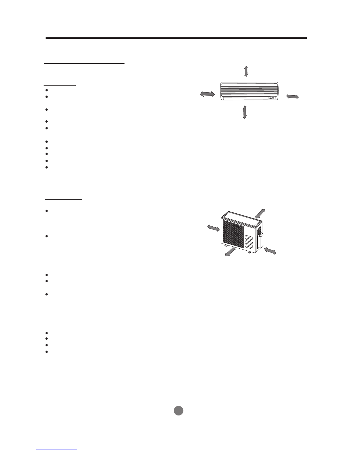
1. Wall-mounted type
INSTALLATION INSTRUCTIONS
Selecting installation place
More than 6in.(15cm)
Read completely, then follow step by step.
Indoor unit
Do not expose the indoor unit to heat or steam.
More than 4.73in.(12cm)
More than 4.73in.( 12cm)
Select a place where there are no obstacles
in front or around the unit.
Make sure that condensation drainage can
be conveniently routed away.
More than 6.57ft( 2.0m)
Do not install near a doorway.
Ensure that the space on the left and right
Fig.1
of the unit is more than 5 inches (12cm).
Use a stud finder to locate studs to prevent unnecessary damage to the wall.
The indoor unit should be installed on the wall at a height of 7 feet (2.0 m) or more from the floor.
The indoor unit should be installed allowing a minimum clearance of 6 inches (15cm) from the ceiling.
Any variations in pipe length will/may require adjustment to refrigerant charge.
There should not be any direct sunlight. Otherwise, the sun will fade the plastic cabinet and
affect its appearance. If unavoidable, sunlight prevention should be taken into consideration.
Outdoor unit
More than 11.9in.( 30cm)
If an awning is built over the outdoor unit to
prevent direct sunlight or rain exposure,
make sure that heat radiation from the
More than 11.9in.
(30
cm)
condenser is not restricted.
Ensure that the clearance around the back
of the unit is more than 12 inches (30cm) and left side is
More than 23.7in.( 60cm)
more than 12 inches (30cm). The front of the unit should
have more than 7 feet (2m) of clearance and the
connection side (right side) should have more
than 24 inches (60cm) of clearance.
More than 6.57ft( 200cm)
Fig.2
Do not place animals and plants in the path of the air inlet or outlet.
Take the air conditioner weight into account and select a place where noise and vibration
will not be an issue.
Select a place so that the warm air and noise from the air conditioner do not disturb neighbors.
Rooftop installation:
If the outdoor unit is installed on a roof structure, be sure to level the unit.
Ensure the roof structure and anchoring method are adequate for the unit location.
Consult local codes regarding rooftop mounting.
If the outdoor unit is installed on roof structures or external walls, this may result in
excessive noise and vibration, and may also
be classed as a non serviceable installation.
3
INSTALLATION INSTRUCTIONS
Tools needed for installation:
Level gauge
Screwdriver
Electric drill, Hole core drill (2.5 inches (65mm))
Flaring tool set
Specified torque wrenches: 13.0 lb.ft., 30.4 lb.ft.,
39.8 lb.ft., 47.7 lb.ft. (different depending on model No.)
Spanner (half union)
Service wrench
Gas-leak detector
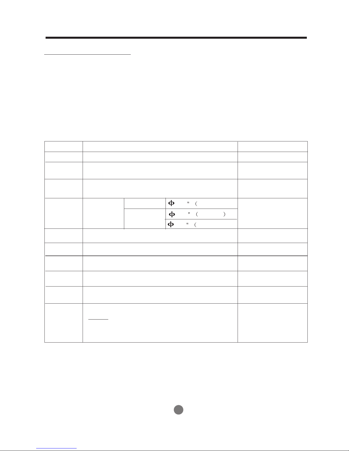
Parts List
Vacuum pump
Gauge manifold
Users manual
Thermometer
Multimeter
Pipe cutter
Measuring tape
Number
1
2
3
4
5
6
7
8
9
10
Name of Part
Installation Plate
Plastic Expansion Sheath
Self-Tapping Screw A ST3.9X25
Connecting
Pipe
Assembly
Liquid side
Gas side
1/4 6.35mm)
3/8 9.53mm
1/2 12.7mm)
Remote Control
Self-tapping Screw B ST2.9X10
Remote Control Holder
Seal (for cooling& heating models only)
Drain Joint
Transfer connector
(NOTE: Pipe size differs from appliance to appliance.
To meet different pipe size requirement, sometimes
the pipe connections need the transfer connector
to install on the outdoor unit .)
(for cooling& heating models only)
( )
Packed with the indoor unit
Qty/one unit
1
5-8
(depending on models)
5-8
(depending on models)
Parts you must purchase
Consult the technician
for the proper size.
1
2
1
1
1
1
(on some models)
4
More than 4.73in.(12cm)
.ni37.4 naht eroM (12cm)
INSTALLATION INSTRUCTIONS
More than 6in.(15cm)
More than
4.73in.(12cm)
2
1
3
More than
)mc21(.ni37.4
Remote
control
Remote
control
retlif riA
More than
4in.(10cm)
Remote
control
Air out
retlif riA
4
6
More th an
23.7i n. ( 60 cm)
More than
11.9in.(30cm)
retlif riA
Remote
control
retlif riA
5
A
More than
23.7in.(60c m)
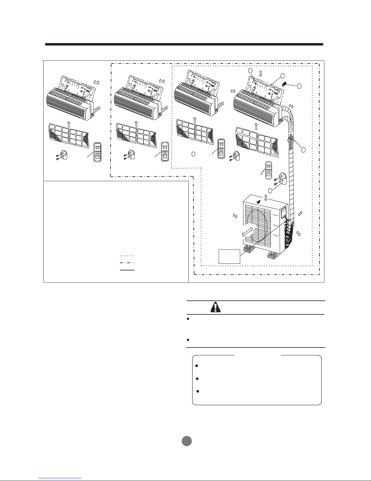
One-Two Zone
One-Three Zone
Mor e than
6.5 7ft( 2.0m )
Loop a
connective
cable
B
C
One-Four Zone
Fig.3
CAUTIONS
This illustration is for explanation purposes only.
The actual shape of your air condtion er may be
slightly different.
Copper lines must be insulated inde pendently.
CAUTION
Use a stud finder to locate studs to prevent
unnecessary damage to the wall.
A minimum pipe run of 10ft (3m) is required
to minimize vibration & excessive noise.
Two of the A, B and C directions should be
free from obstructions.
5
INSTALLATION INSTRUCTIONS
Indoor unit installation (wall-mounted type)
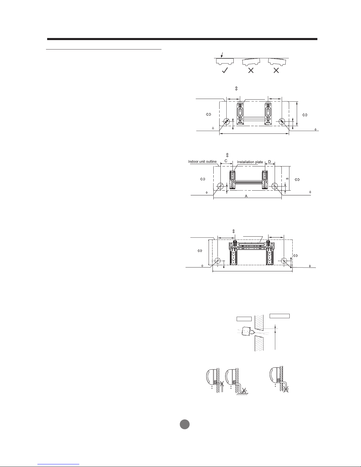
1. Fit the Installation Plate
1. Fit the installation plate horizontally
on structural parts of the wall with
spaces around the installation plate.
2. If the wall is made of brick, concrete
or the like, drill five or eight 0.197 inches ( 5mm)
diameter holes in the wall. Insert Clip anchor
for appropriate mounting screws.
3. Fit the installation plate on the wall
with five or eight type “A” screws.
Not e:
Fit the Installation Plate and drill
holes in the wall according to the
wall structure and corresponding
mounting points on the installation
plate. The Installation Plate may be
slightly different according to the
different models of indoor unit.
(Dimensions are in “inch” unless
otherwise stated)
Indoor unit outline
4.8in.(120mm) or
more to wall
Left rear side
refrigerant
pipe hole 2.6
4.8in.(120mm) or
more to wall
Left rear side
refrigerant
pipe hole 2.6in.
Correct orientation
of Installation Plate
Fig.4
6in.(150mm) or more to ceiling
C
Installation plate
1.8
A
Model A (A: 28, B: 9.84, C:3.94, D: 4.33)
Model B( )A: 31.1, B:10.43, C:3.94, D: 5.9
6in.(150mm) or more to ceiling
1.8
Model A (A: 28, B: 9.84, C: 3.94, D: 4.33)
Model B( )A: 31.1, B:10.8, C:3.94, D: 3.35
Model C( )A: 33.5, B:11.4, C:3.94, D: 4.53
D
4.8in.(120mm)
or more to wall
B
Right rear side
1.8
refrigerant
pipe hole 2.6in.
4.8in.(120mm)
or more to wall
Right rear side
refrigerant
1.8
pipe hole 2.6in.
4.8in.(120mm) or
more to wall
2. Dr ill a hole in th e wall
1. Determine hole positions according
to the diagram detailed in Fig.5. Drill
one (1) hole (2.5 inches (65mm)) slanting slightly
to outdoor side.
3. Connective Pipe and Drainage
Installation
Drainage
1. Run the drain hose sloping downward.
Do not install the drain hose as
illustrated in Fig.7.
Indoor unit outline
Left rear side
refrigerant
pipe hole 2.6
Do not block water flow by a rise.
5.91in.
11.5in.
1.8
Model A (A: 36.2, B: 11.5, C:5.9, D: 7.3)
Model B( )A: 39.2, B:11.5, C:5.9, D:7.9
Model C( )A: 33.5, B:12, C:5.9, D:5.7
6in.(150mm) or more to ceiling
Installation plate
36.14in.
7.28in.
Fig.5
Wall
Indoor
Outdoor
)
5-7 mm
(
0.2 -0 .3 in .
Fig.6
Do not put the end of
drain hose into water.
Fig.7
4.8in.(120mm)
or more to wall
Right rear side
refrigerant
1.8
pipe hole 2.6in.
6
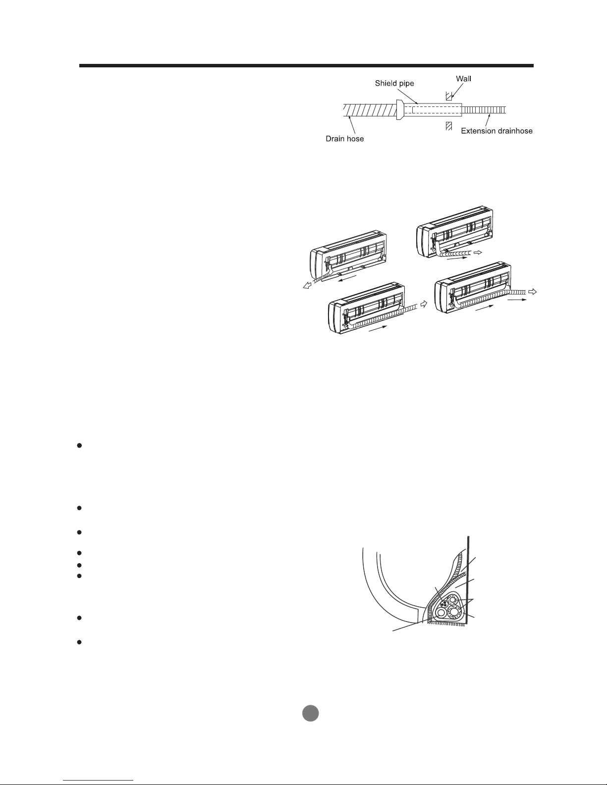
2. When connecting extension drain hose,
insulate the connecting part of extension
drain hose with a shield pipe, do not let
the drain hose slack.
INSTALLATION INSTRUCTIONS
Connective pipe installation
1. For the left-hand and right-hand piping,
remove the pipe cover from the side
panel.
2. For the rear-right-hand and rear-left-hand
piping, install the piping as shown in Fig.10.
3. Fix the end of the connective pipe. (Refer
to Tightening Connection in REFRIGERANT
PIPING CONNECTION)
4. Piping and wrapping
Bundle the tubing, connecting cable, and drain
hose with tape securely, evenly as shown in
Fig.11.
Because the condensed water from rear of the
indoor unit is gathered in evaporative drain pain
box and is piped out of room do not put anything
else in the box.
Right-hand piping
Left-hand piping
Fig.9
Fig.8
Rear-right piping
Rear-left piping
Fig.10
CAUTION
Connect the indoor unit first, then the
outdoor unit.
Do not allow the piping to let out from
the back of the indoor unit.
Be careful not to let the drain hose slack.
Heat insulated both of the auxiliary piping.
Be sure that the drain hose is located at
the lowest side of the bundle. Locating
at the upper side can cause drain pan
to overflow inside the unit.
Never intercross nor intertwist the power
wire with any other wiring.
Run the drain hose sloped downward to
drain out the condensed water smoothly.
7
Drain hose
Indoor unit
Connective
cable
Fig.11
Ponding box
Pipe room
Connective
pipe
Wrapping belt
 Loading...