

Perfect Aire 1PAMSH09-SZW-15, 1PAMSH09-SZW-14.5, 1PAMSH09-SZO-15, 1PAMSH12-SZO-15, 1PAMSH18-SZO-15 Installation Manual
...Page 1
COMFORT...BUILT TO LAST
9,000, 12,000 and 18,000 BTU
SINGLE-ZONE DUCTLESS
MINI-SPLIT SYSTEM
Heat Pump
INSTALLATION
MANUAL
INDOOR UNIT:
1PAMSH09-SZW-14.5
1PAMSH09-SZW-15
1PAMSH12-SZW-15
1PAMSH18-SZW-15
OUTDOOR UNIT:
1PAMSH09-SZO-14.5
1PAMSH09-SZO-15
1PAMSH12-SZO-15
1PAMSH18-SZO-15
Before using your air conditioner, please read
this manual carefully and keep it for future
reference, along with your receipt.
Page 2

Contents
This manual provides the information needed for proper use and maintenance of this air conditioner. Basic preventative
care can help extend the life of this unit. The “Troubleshooting Tips” section in this manual contains a chart with solutions
to the most common problems. Referring to this section may save time and prevent the need for a service call in the event
of a problem.
Safety Precautions
Installation Precautions .............................................................................................................................................2
Warning .....................................................................................................................................................................2
Caution ......................................................................................................................................................................2
Installation Instructions
Selecting installation location ................................................................................................................................ 3–4
Accessories ...............................................................................................................................................................4
Indoor unit installation............................................................................................................................................ 5–7
Outdoor unit installation ......................................................................................................................................... 8–9
Air Purging and Test Operation
Air Purging and Test Operation ........................................................................................................................... 9–10
-1-
Page 3
Safety Precautions
INSTALLATION PRECAUTIONS
• Read this installation manual carefully before operating the unit to ensure correct installation.
• Installation must be performed in accordance with the requirement of NEC and CEC by a trained service
technician only.
• Contact a trained service technician for repair, maintenance and installation of this unit.
• The air conditioner is not intended for use by young children without supervision. Young children should be
supervised to ensure that they do not play with the air conditioner.
• Disabled persons may require assistance with set up.
• All pictures in these instructions are for explanation purposes only.
• The design and specications of this system are subject to change without prior notice.
To prevent injury to the user or other people and property damage, the following instructions must be followed. Incorrect
operation due to ignoring instructions may cause harm or damage.
Failure to adhere to each of the following precautions can lead to results classied as follows:
! !
!
1. Install according to these installation instructions. Defective/incorrect installation can result in water leakage,
electrical shock or re .
2. Install the indoor unit per these instructions. Make sure it is secured properly to the wall. If not installed properly, the
unit could drop or fall, causing injury.
3. An independent circuit breaker must be used for each indoor unit. If the circuit breaker is not sized properly, electrical
shock and/or a re can result.
4. Use the specied cable and connect it properly to the terminals. If connection is not perfect, it can cause the
connection to heat up and possibly set re.
5. Routing of the wiring must be properly arranged so the control board cover is xed properly. If the control board cover
is not xed perfectly, it can cause the connection to heat up, set re, or electrical shock.
6. When connecting the refrigerant piping, make sure no debris or foreign matter gets into the refrigerant piping.
!
• This equipment must be grounded properly. Follow the local and national codes when choosing the proper outdoor
electrical disconnect. The unit will not run properly and could cause an electrical shock if not installed properly.
• Do not install this unit in a place where leakage or ammable gas may occur. A gas leak near the unit can cause re.
• Carry out drainage piping as mentioned in installation instructions. If drainage is not installed properly, water could
back up in the system and cause water damage.
WARNING
!
CAUTION
WARNING - This symbol indicates the possibility of death or serious injury.
CAUTION - This symbol indicates the possibility of injury or damage to property.
!
-2-
Page 4
Installation Instructions
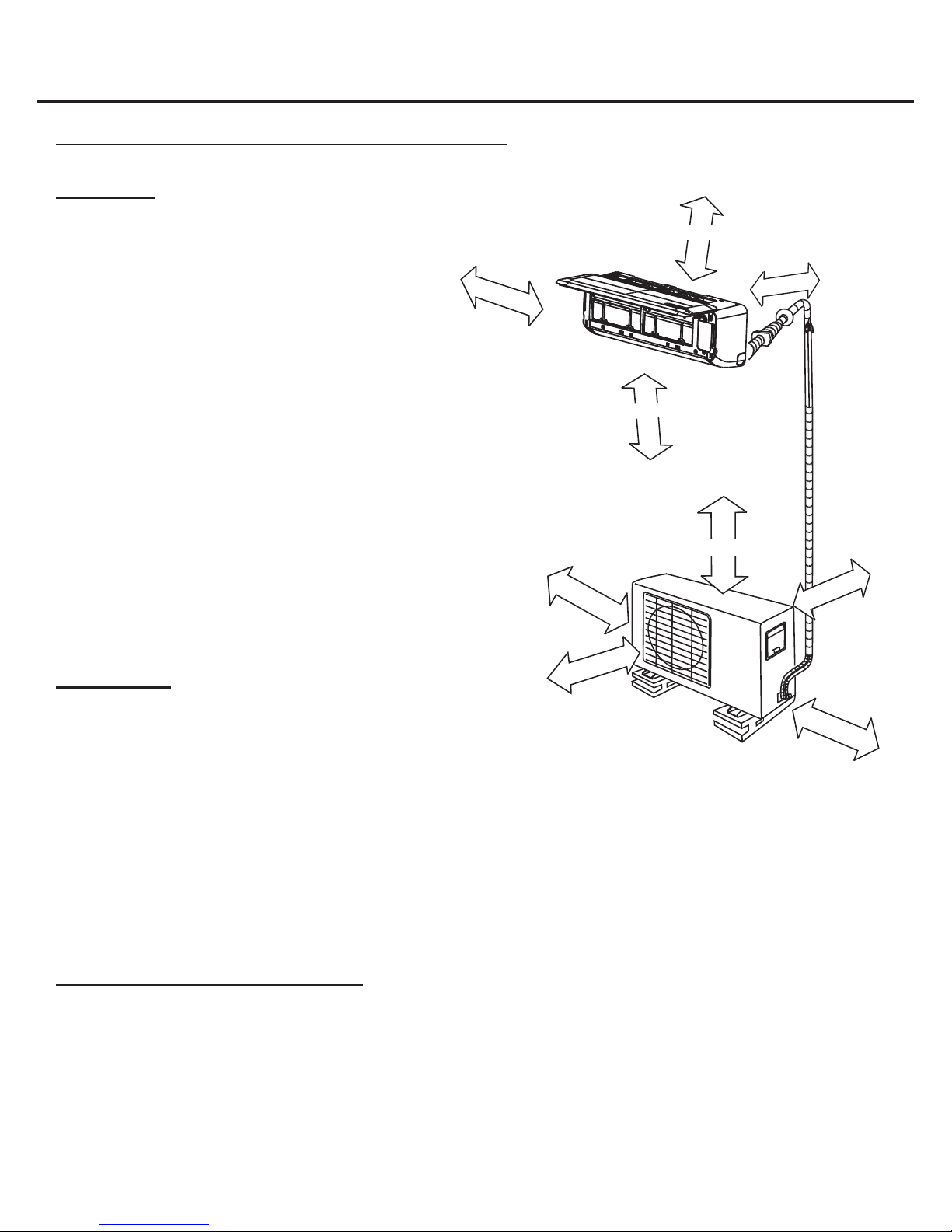
Selecting an installation location
Please read through the following directions completely before installing. When installing, follow these step by step.
Indoor Unit
• Do not expose the indoor unit to heat or steam.
• Select a place where there are no obstacles in front
or around the unit and the air circulation in the room
is good.
• Make sure that condensation drainage can be
conveniently routed away.
• Select a location where noise prevention is taken into
consideration.
• Do not install near a doorway.
• Ensure that the space on the left and right of the unit
is more than 4.75 in. (12 cm).
• Use a stud nder to locate studs to prevent
unnecessary damage to
the wall.
• The indoor unit should be installed on the wall at a
height of 7.55 ft
(2.3 m) or more from the oor.
• The indoor unit should be installed allowing a
minimum clearance of
6 in. (15 cm) from the ceiling.
• There should not be any direct sunlight. Sunlight will
fade the plastic cabinet and affect its appearance.
≥ 4.8 in.
≥ 11.9 in.
≥ 7.5 ft
≥ 6 in.
≥ 23.7 in.
Fig. 1
≥ 4.8 in.
≥ 11.9 in.
Outdoor Unit
• If an awning is built over the outdoor unit to prevent
direct sunlight or rain exposure, make sure that heat
radiation from the condenser is not restricted.
• Do not place animals and plants in the path of the air
inlet or outlet.
• Refer to Fig. 1, which notes the amount of space there must be between the unit and any walls, ceiling, fences, and
other obstacles/items.
• Install the outdoor unit on concrete or plastic pad or mount to a wall with the proper brackets (see section below) and
secure per local and national codes. Make sure the unit is level.
• Install the outdoor unit in a location where the noise and vibration level will not be an issue.
• Select a location where the warm air and noise from the outdoor unit does not disturb neighbors.
• Do not place any items near the unit that will cause a short circuit of the discharged air.
≥ 6.75 ft
≥ 23.7 in.
Outdoor Unit - Rooftop Installation
• If the outdoor unit is installed on a roof, be sure to level the unit.
• Ensure the roof structure and anchoring method are adequate for the unit location.
• Consult local codes regarding rooftop mounting.
• If the outdoor unit is installed on a roof structure or external walls, this may result in excessive noise and vibration, and
may also be classied as a non-serviceable installation.
-3-
Page 5

Settling of Outdoor Unit
Installation Instructions (cont.)
• The outdoor unit should be installed on a concrete or plastic pad or mounted to
a wall with the proper brackets and secured per local and national codes.
• NOTE: The outdoor unit you purchase may be like one of the following.
Install the outdoor unit according to the applicable unit using the dimensions in
the table below.
Outdoor Unit Dimensions
(WxHxD) (inches)
27.6 x 21.3 x 9.5 18.1 9.9
30.8 x 21.3 x 9.9 21.6 10.9
30 x 23.3 x 11.3 20.9 11.5
Mounting Dimensions
A (inches) B (inches)
Fig. 2
Fig. 3
W
A
Air inlet
Air inlet
D
Air outlet
Accessories
Number Name of Accessory Quantity
1 Installation Plate 1
2 Clip Anchor 5 – 8 (depends on model)
3 Self-tapping Screw A ST3.9x25 5 – 8 (depends on model)
4 Seal (for cooling & heating models only) 1
5 Drain Joint (for cooling & heating models only) 1
6 Connecting
pipe
assembly
7 Remote control 1
8 Self-tapping Screw B ST2.9x10 optional parts 2
9 Remote control holder optional part 1
10 Air freshening lter (installed on air lter) 1
Liquid side Φ 1/4" (6.35 mm) Parts you must
Φ 3/8" (9.52 mm)
Gas side Φ 3/8" (9.52 mm)
Φ 1/2" (12.7 mm)
Φ 5/8" (16 mm)
purchase. The pipe size
differs from appliance to
appliance. Consult the
technician for the proper
size.
B
NOTE: The parts listed above are included with this unit. Any other required tools/items for installation must be purchased.
CAUTION - Use a stud nder to locate studs to prevent unnecessary damage to the wall.
!
-4-
Page 6

Installation Instructions (cont.)
Indoor Unit Installation
1. Install the Installation Plate
• Fit the installation plate horizontally on
structural parts of the wall with space around
the installation plate.
• If the wall is made of brick, concrete or the
like, drill ve or eight 0.2 in. diameter holes
in the wall. Insert clip anchor for appropriate
mounting screws.
• Fit the installation plate on the wall with ve
or eight type “A” screws.
NOTE:
Mount the Installation Plate and drill holes
in the wall according to the wall structure
and corresponding mounting points on the
installation plate. The Installation Plate
provided with the machine differs based on the
model being installed.
(All units are in inches unless otherwise noted.)
Fig. 4
Correct orientation
of Installation Plate
Fig. 5
4.8 in. or
more to wall
Left rear side
refrigerant pipe
hole Φ 2.6 in.
4.8 in. or
more to wall
Left rear side
refrigerant pipe
hole Φ 2.6 in.
4.8 in. or
more to wall
Left rear side
refrigerant pipe
hole Φ 2.6 in.
C
9000 Btu/h models (A:26.8, B:10.1, C:6.7, D:3.7)
C
C
18000 Btu/h models (A:35.6, B:10.8, C:3.2, D:4)
6 in. or more to ceiling
12000 Btu/h models (A:30.3, B:10.1, C:6.7, D:3.7)
6 in. or more to ceiling
6 in. or more to ceiling
A
A
A
D
D
Indoor unit outline
D
Indoor unit outline
4.8 in. or
more to wall
B
Right rear side
refrigerant pipe
hole Φ 2.6 in.
Indoor unit outline
4.8 in. or
B
more to wall
Right rear side
refrigerant pipe
hole Φ 2.6 in.
4.8 in. or
B
more to wall
Right rear side
refrigerant pipe
hole Φ 2.6 in.
2. Drill a hole in the wall
• Determine hole positions according to left and right side of the installation plate; see
the diagram detailed in Figure 5 on the previous page of this manual. The hole center is
obtained by measuring the distance as shown in Figure 5.
• Drill the piping plate hole with Φ2.5 inch hole-core drill. Drill the piping hole at either the
right or the left. The hole should be slightly slanted to the outdoor side.
• Always take steps to protect the pipe when drilling metal grids, metal plates, or the like.
Fig. 6
0.2– 0.3 in.
-5-
Page 7

Installation Instructions (cont.)
Terminal block of indoor unit
Cord clamp
L1 L 2 S
L1 L 2 S
or
3. Connect the cable to the Indoor unit
Electrical Work
Electric safety regulations for the initial installation:
• If there are any safety concerns with the electrical power supply, the technician should consult a certied electrician
and have the problem resolved before installing the unit.
• Power voltage should be in the range of 90%~110% of rated voltage.
• The circuit breaker at the electrical panel should be no more than 1.5 times the max current of the outdoor unit. All
the electrical information is located on the reverse side of the electrical cover on the outdoor unit. Follow all local and
national electric codes.
• Each outdoor unit must have its won circuit breaker.
• Install the proper sized electrical wire from the circuit breaker located at the electrical panel to an outdoor
weatherproof disconnect.
• The outdoor unit must be grounded per code. If the unit is not grounded it will not operate per system specications.
• Install a liquid tight electrical whip from the outdoor disconnect to the outdoor unit.
• All wiring must comply with local and national codes and be installed by a certied electrician.
Suggested Minimum Wire Size
(AWG: American Wire Gauge)
Appliance
Amps
10 18
13 16
18 14
25 12
AWG Wire
Size
NOTE:
The cable size and the current of the
fuse or switch are determined by the
maximum current indicated on the
nameplate, which is located on the side
panel of the unit. Please refer to the
nameplate before selecting the cable,
fuse and switch.
30 10
Connect the Cable to the Indoor Unit
NOTE: Before performing any electrical work, turn off the power at the main
panel to the unit.
• The inside and outside connecting cable can be connected without
removing the front grille.
• Lift the indoor unit panel up; remove the electrical box cover by loosening
the screw.
• Ensure the color of wires of outdoor unit and the terminal numbers are the
same to the indoor units respectively.
• Wrap those cables not connected with terminals with insulation tape so that
they will not touch any electrical components. Secure the cable onto the
control board with the cord clamp.
Fig. 7
Front Panel
Terminal block of indoor unit
L1 L 2 S
To outdoor unit
or
Cord clamp
L1 L 2 S
Electrical box
cover
To outdoor unit
-6-
Page 8

Installation Instructions (cont.)
4. Connective Pipe and Drainage Installation
Drainage
• Run the drain hose sloping downward. Do not install the drain hose as
illustrated in the "wrong" gures in Figure 8.
• When connecting extension drain hose, insulate the connecting part of
extension drain hose with a shield pipe. Do not let the drain hose slack.
Installation of Connective Pipe
• For the left-handed and right-handed piping, remove the pipe cover
from the side panel.
• For the right back and left back piping, install the piping as shown in
Fig. 9 and Fig. 10.
NOTE: One side drainage structure is standard. Both sides drainage
structure is optional and can only be customized from factory. For both
sides drainage structure, it can be chosen for right, left, or both sides
drainage connection. If choosing both sides drainage connection,
another proper drain hose is needed as there is only one drain hose
offered by factory. If choosing one side drainage connection, make sure
the drain hole on the other side is well plugged.
For 9K/12K models, if choosing right side drainage connection, please
choose right-hand or right-back piping. The connection of the drain hose
is supposed to be done by a qualied installer in case of water leakage.
• Bundle the tubing, connecting cable, and drain hose with tape securely
and evenly as shown in the gures on the right.
NOTE: Because the condensed water from rear of the indoor unit
is gathered in the drain pan and is piped out of the room, do not put
anything else in the drain pan.
Fig. 8
Rig ht Wro n g
Fig. 9
Fig. 10
CAUTION
• Connect the indoor unit rst, then the outdoor unit.
• Be careful not to let the drain hose slack.
• Heat insulation should be done to the extension drain hose of indoor unit.
• Be sure that the drain hose is located at the lowest side of the bundle.
Locating at the upper side can cause drain pan to overow inside the unit.
• Never inter-cross nor inter-twist the power wire with any other wiring.
• Both the liquid and suction refrigerant lines must be insulated.
Indoor Unit Installation
• Pass the piping through the hole in the wall.
• Hook the indoor unit onto the upper portion of installation plate.
(Engage the indoor unit with the upper edge of the installation plate.)
Ensure the hooks are properly seated on the installation plate by
moving it in left and right.
• Piping connections can be easily made by lifting the indoor unit with a
cushioning material between the indoor unit and the wall. Remove after
nished piping.
• Press the lower left and right side of the unit against the installation
plate until hooks engage with the slots.
Fig. 11
Fig. 12
-7-
Page 9

Installation Instructions (cont.)
Outdoor Unit Installation
IMPORTANT: See pages 3 – 4 of this manual for instructions regarding the outdoor unit's installation location.
1. Outdoor Unit Installation Precautions
• Install the outdoor unit on a rigid base to prevent increased noise level and vibration.
• Determine the air outlet direction where the discharged air is not blocked.
• In the case that the installation place is exposed to strong wind such as seaside, make sure the fan operates properly
by putting the unit lengthwise along the wall or using a dust or shield plate.
• The connection between the bracket and the wall and that between the bracket and the air conditioner should be rm,
stable, and reliable.
• In windy areas, install the unit to prevent the admission of
wind. If suspending installation is required, the installation
bracket should be in accordance with technical requirements
in the installation bracket diagram. The installation wall should
be solid brick, concrete, or the same intensity of construction,
or the installer should take action to reinforce it.
• Be sure there are no obstacles blocking air radiating from the unit.
2. Drain Joint Installation
NOTE: The drain joint will differ slightly based on the model being installed.
• For the drain joint with the seal (Fig 14A), rst t the seal onto the drain joint, then
insert the drain joint into the base pan hole of outdoor unit. Rotate 90º to securely
assemble them.
• To install drain joint as shown in Figure 14B, insert the drain joint into the base pan
hole of outdoor unit until it remains xed with a clicking sound. Connecting the drain
joint with an extension drain hose (purchased locally) in case the water drains of the
outdoor unit during the heating mode.
Fig. 13
Strong
wind
Incorrect
Barrier
Stron g
wind
Fig. 14
Drain joint
Seal
(A) (B)
Correct
Base pan hole
of outdoor uni t
3. Refrigerant Pipe Connection
Flaring
• Cut the cooper tube with a pipe cutter. Clean and remove any burrs from
the end of the pipe.
• Remove the are nuts attached to the indoor and outdoor unit. Slide the
nuts on the copper tube.
• Insert copper tube into a aring block and use the table to the right to
determine how much tube should be above the black before aring the
tube. You can also gure the thickness of a nickel to use as a standard.
Tightening Connection
• Align the tube to the proper connections on the indoor and outdoor units.
• Sufciently tighten the are nut with ngers and then tighten it with a
crescent wrench and torque wrench as shown in Figure 15.
• Excessive torque can break nut depending on installation connections.
Outer Diameter.
(in.)
Φ 1/4" 1500 (153 kgf.cm) 1600 (163 kgf.cm)
Φ 3/8" 2500 (255 kgf.cm) 2600 (265 kgf.cm)
Φ 1/2" 3500 (357 kgf.cm) 3600 (367 kgf.cm)
Φ 5/8" 4500 (459 kgf.cm) 4700 (479 kgf.cm)
Tightening Torque
(N.cm)
Additional Tightening
Torque (N.cm)
Outer
Diameter (in.)
A (in.)
Max. Min.
Φ 1/4" 0.052 0.03
Φ 3/8" 0.063 0.04
Φ 1/2" 0.071 0.04
Φ 5/8" 0.087 0.079
Fig. 15
O
Oblique
"A"
Roughness
Bar
Clamp handle
Burr
90
Bar
Copper pipe
Indoor unit tubing Flare nut Pipings
Handle
-8-
Page 10

Air Purging and Test Operation
4. Connect the Cable to the Outdoor Unit
• Remove the electrical control board cover from the outdoor unit by loosening the screw.
• Attach the electrical whip from the outdoor disconnect to the proper connections shown in the wiring diagram.
• Connect the cables from the indoor unit as identied with their respective matching numbers on the terminal block of
the indoor unit.
• Secure the cables on the control board with the supplied clamp.
• Do not allow any bare wires to touch any other wires or metal parts.
Terminal block of outdoor unit
L1 L2 S L1 L 2
To ind oor un it
To power sup pl y
Fig. 16
Cover
Screw
L1 L2 S L1 L 2
To ind oor un it
To power sup pl y
Fig. 17A Fig. 17B
Air Purging and Test Operation
Air Purging
• The indoor unit and tubing between the indoor and outdoor unit must be leak tested and evacuated to remove any
noncondensables and moisture from the system.
• Check that each tube (both liquid and gas side tubes) between the indoor and outdoor units have been properly
connected and all wiring for the test run has been completed.
• Pipe length and refrigerant amount indicated in the chart below:
Connective
pipe length
Less than 16.4 ft Use vacuum pump ------------------------------------
More than 16.4 ft Use vacuum pump
Air purging method Additional amount of refrigerant to be charged
9k, 12k, 18k (Liquid side Φ 1/4")
R410A: 0.212 oz/ft
22k (Liquid side Φ 3/8")
R410A: 0.423 oz/ft
• For the R410A refrigerant model, make sure the refrigerant added into air conditioner is liquid form in any case.
• When relocating the unit to another place, use vacuum pump to perform evacuation.
CAUTION:
• Open the valve stem until it hits against the stopper. Do not try
to open it further.
• Securely tighten the valve stem cap with a spanner or the like.
• Valve stem cap tightening torque. See Tightening Torque Table
on previous page of this manual.
-9-
Fig. 18
Outdoor
unit
Refrigerant
A
B
Packed valve
Gas side
Liquid side
Indoor
unit
C
D
Flare nut
Valve body
Valve stem
Flare nut
Stopper
Cap
Page 11

Air Purging and Test Operation (cont.)
When Using the Vacuum Pump
• Completely tighten the are nuts (A, B, C, D). Connect the manifold valve charge hose to a charge port of the packed
valve on the gas pipe side.
• Connect the charge hose connection to the vacuum pump.
• Fully open the handle Lo of the manifold valve.
• Operate the vacuum pump to evacuate. After starting evacuation, slightly loosen the are nut of the packed valve on
the gas pipe side and check that the air is entering. (Operation noise of the vacuum pump changes and a compound
meter indicates 0 instead of minus.)
• After the evacuation is complete, fully close the handle Lo of the manifold valve and stop the operation of the vacuum
pump. Make evacuation for 15 minutes and more and check that the compound meter indicates -76cmHg(-1.0x10⁵Pa).
• Turn the stem of the packed valve B about 45º counter-clockwise for 6~7 seconds after the gas comes out, then tighten
the are nut again. Make sure the pressure display in the pressure indicator is a little higher than the atmosphere
pressure.
• Remove the charge hose from the Low pressure charge hose.
• Fully open the packed valve stems B and A.
• Securely tighten the cap of the packed valve.
Safety and Leakage Check
• Soapy water method:
Apply a soapy water or neutral liquid detergent on the indoor unit connections and
outdoor unit connections using a soft brush to check for leakage of the connecting
points of the piping. If bubbles come out, this indicates that the pipes have leakage.
• Leak detector:
Use the leak detector to check for leakage.
CAUTION - See Figure 20:
A: Lo packed valve B: Hi packed valve
C and D are ends of indoor unit connection
Fig. 20
Indoor unit
check point
Cover
Outdoor unit
check point
Test Running
Perform test operation after completing gas leak check at the are nut connections and electrical safety check:
• Check that all tubing and wiring have been properly connected.
• Check that the gas and liquid side of service valves are open.
• Connect the power; press the ON/OFF button the remote control to turn the unit on.
• Use the MODE button to select COOL, HEAT, AUTO and FAN, making sure all of the functions work well.
• When the ambient temperature is too low (lower than 62.6º F), the unit cannot
be controlled by the remote control to run at cooling mode; manual operation
can be taken. Manual operation is used only when the remote control is
disabled or maintenance is necessary:
• Hold the panel sides and lift the panel up to an angle until it remains xed
with a clicking sound.
• Press the Manual control button to select the AUTO or COOL; the unit
will operate under forced AUTO or COOL mode. (See user manual for
details.)
• The test operation should last about 30 minutes.
Fig. 21
Manual control
button
AUTO/COOL
C
D
A
B
-10-
Page 12

COMFORT...BUILT TO LAST
Distributed by:
Perfect Aire, LLC
5151 Belt Line Rd.
Suite 878
Dallas, TX 75254
877-365-6274
www.perfectaire.us
Specification and performance data is subject to change without notice.
Printed in China
 Loading...