


DirectVision®
TECHNICAL REFERENCE
MANUAL

DirectVision® Technical Reference Manual
Page ii

DirectVision® Technical Reference Manual
Table of Contents
WARNINGS & CAUTIONS ................................................................... 1
DOCUMENTATION CONVENTIONS .............................................................. 1
GENERAL WARNINGS .............................................................................. 1
GENERAL CAUTIONS ............................................................................... 2
PRODUCT DESCRIPTION ..................................................................... 4
CAMERA HANDPIECE............................................................................... 4
Visual Guide Interface ................................................................... 5
Camera Control Unit Interface ...................................................... 6
Storage during Transportation ..................................................... 7
CAMERA CONTROL UNIT ......................................................................... 8
Front Panel Controls ...................................................................... 8
Electronic Interfaces ...................................................................... 9
COLOR MONITOR DISPLAY ..................................................................... 10
LED Indicator ............................................................................... 10
Control Dial ................................................................................. 11
Monitor Power ON/OFF .............................................................. 11
Menu Control .............................................................................. 11
CART ................................................................................................. 13
Workspace .................................................................................. 13
Storage Area ............................................................................... 13
Swivel Arm .................................................................................. 13
Power .......................................................................................... 13
Height Adjustment ...................................................................... 14
Casters ........................................................................................ 14
Power Cord .................................................................................. 15
DIRECTVISION® GUIDE .......................................................................... 16
Features ...................................................................................... 16
DIRECTVISION® CATHETER ..................................................................... 18
Features ...................................................................................... 19
Page iii

DirectVision® Technical Reference Manual
INITIAL SYSTEM ASSEMBLY .............................................................. 21
REQUIRED COMPONENTS ....................................................................... 21
REQUIRED HARDWARE AND TOOLS .......................................................... 21
INITITAL ASSEMBLY & TEST..................................................................... 21
MONITOR SETUP ............................................................................. 31
CONTROL DIAL DEFINITIONS ................................................................... 31
MONITOR DEFAULT VALUES ................................................................... 31
CAMERA CONTROL UNIT CALIBRATION PROCEDURES ..................... 33
PRECONDITIONS ................................................................................... 33
CAMERA CONTROL UNIT FRONT PANEL .................................................... 33
PROCEDURES ....................................................................................... 34
Window Size ................................................................................ 34
Auto Gain Control ........................................................................ 35
White Balance Adjustment .......................................................... 36
Focus ........................................................................................... 39
SYSTEM MAINTENANCE .................................................................. 40
CAMERA CONTROL UNIT FUSE ................................................................ 40
TROUBLESHOOTING ........................................................................ 41
TECHNICAL SPECIFICATIONS ............................................................ 46
DIMENSION & WEIGHT ......................................................................... 46
Camera Control Unit .................................................................... 46
Monitor ....................................................................................... 46
Cart .............................................................................................. 46
ELECTRICAL SPECIFICATIONS ................................................................... 46
Camera Control Unit .................................................................... 46
Monitor ....................................................................................... 47
CAMERA SPECIFICATIONS ....................................................................... 47
VISUAL GUIDE SPECIFICATIONS ................................................................ 48
OPERATING ENVIRONMENT .................................................................... 48
Camera Control Unit and Camera Handpiece ............................. 48
Monitor ....................................................................................... 48
Page iv

DirectVision® Technical Reference Manual
Cart ............................................................................................. 48
STORAGE ENVIRONMENT ....................................................................... 49
SPARE PARTS ....................................................................................... 49
Camera Control Unit ................................................................... 49
WARRANTY, SERVICE & CLAIMS....................................................... 49
REFERENCES ..................................................................................... 49
Page v


DirectVision® Technical Reference Manual
!
Warnings & Cautions
Documentation Conventions
Please read this manual and follow its instructions carefully. The
words: Warning, Caution, and Note carry special meaning and
should be reviewed carefully:
The personal safety of the patient or user may
Warning:
be involved. Disregarding this information could
result in injury to the patient or user.
Caution:
Note:
Special service procedures or precautions must
be followed to avoid damage to the equipment.
Special information to make maintenance easier
and important information more clear.
An exclamation point within a triangle alerts the
user of risk of danger; attention, consult
company documents.
General Warnings
It is important to read and understand this manual. Failure to
follow these instructions may cause damage to the product or
harm to the patient and/or the user. The user should do the
following:
1. Warning: Read the DirectVision
Manual before assembling and using the product.
2. Warning: Federal (USA) Law restricts this device to use by
or on the order of a physician.
3. Warning: Never look directly at the light emitted from the
light source of the camera handpiece or the DirectVision
Guide. Damage to eye may result.
®
Technical Reference
®
Page 1 of 49

DirectVision® Technical Reference Manual
4. Warning: Never leave the DirectVision® System powered
and unattended. Heat from the light source could ignite
drapes or other materials.
5. Warning: Do not store or use the DirectVision® System in
an environment that contains flammable gases which can
result in an explosion.
6. Warning: The DirectVision® System must only be repaired
by personnel authorized by PercuVision®. Unauthorized
repairs could compromise the safety and integrity of the
product and voids the warranty.
Failure to follow the instructions in this manual could void the
warranty.
PercuVision® reserves the right to improve our product. As a
result, product may not conform in detail to published design or
specifications. Improvements are subject to change without
notice. Please contact PercuVision® customer care department
for information on improvements and new products.
General Cautions
1. Caution: Carefully unpack the shipment and check for
physical damage. If damage is observed, please refer to the
Service and Claims Section in DirectVision® Technical
Reference Manual.
2. Caution: Do not use the DirectVision® System until you have
verified that it is properly assembled, setup and functioning
correctly.
3. Caution: Use only in conjunction with other Type BF or CF
rated medical electrical equipment approved to IEC 60601-1
or equivalent standard.
4. Caution: Never attempt repairs or maintenance to the
DirectVision® System before reviewing the Service and
Claims Section of DirectVision® Technical Reference
Manual.
Page 2 of 49

DirectVision® Technical Reference Manual
5. Caution: To prevent damage to the DirectVision® Guide and
camera handpiece, always handle with care. Do not drop,
crush, cut, or bend any portion of the visual guide beyond
a 2” radius. Although the visual guide is flexible, bending
beyond the specified radius could cause breakage in the
fiber optic bundle, which reduces its useful life. Kinking the
visual guide could break the entire fiber optic bundle which
can render it non-operational.
6. Caution: Do not expose the DirectVision® System to
excessive heat which can cause damage.
7. Caution: Never place heavy objects on the DirectVision®
System.
Page 3 of 49
DirectVision® Technical Reference Manual
Product Description
DirectVision® product line consists of:
• DirectVision® System
– Camera Handpiece
– Camera Control Unit (CCU)
– Monitor Display
– Cart
• DirectVision® Guide
• DirectVision® Catheter
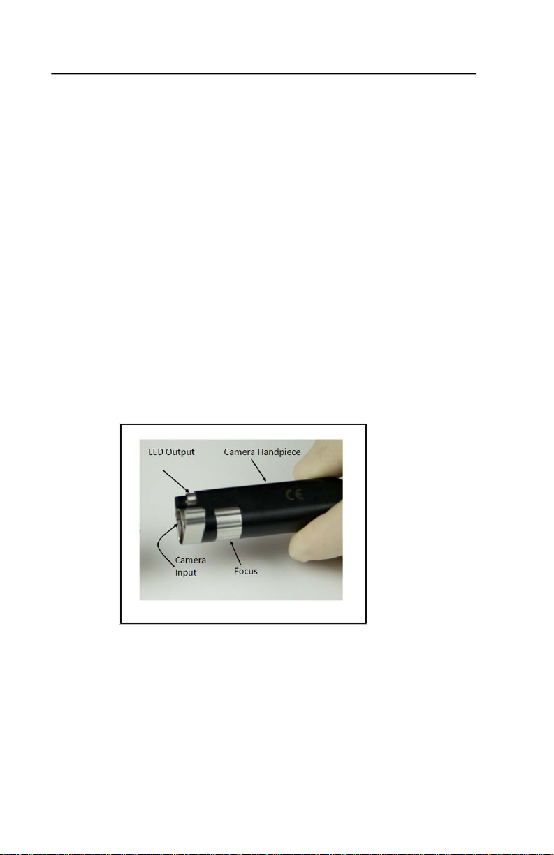
Camera Handpiece
The camera handpiece contains the camera, optics to focus the
video image and an LED white light source. Camera operation is
dependent on receiving power and input video control signals
from the CCU. It uses the input control signals to produce
streaming video output .
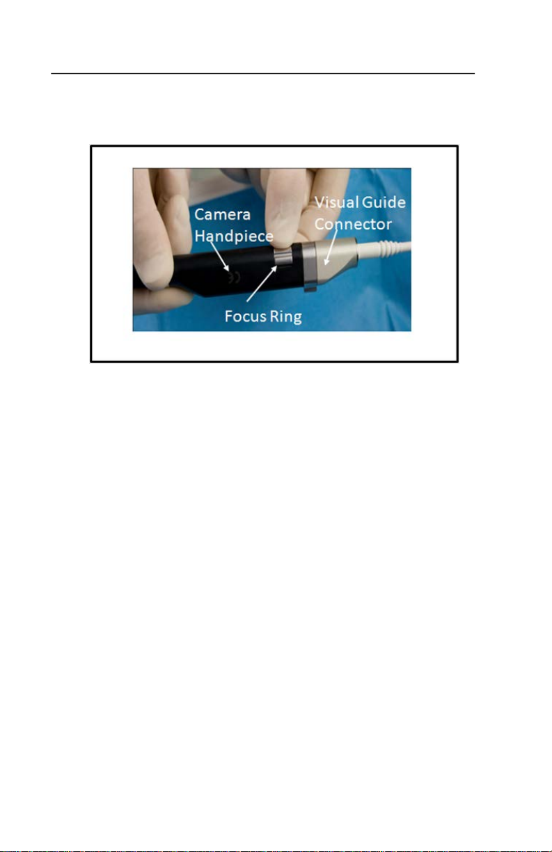
The camera handpiece has a locking swing arm to securely couple
the camera handpiece to the DirectVision® Guide. The body of
the camera handpiece has a Focus Ring, which provides focus for
the video image.
Page 4 of 49

DirectVision® Technical Reference Manual
The camera handpiece provides two interfaces:
• Visual Guide
• CCU
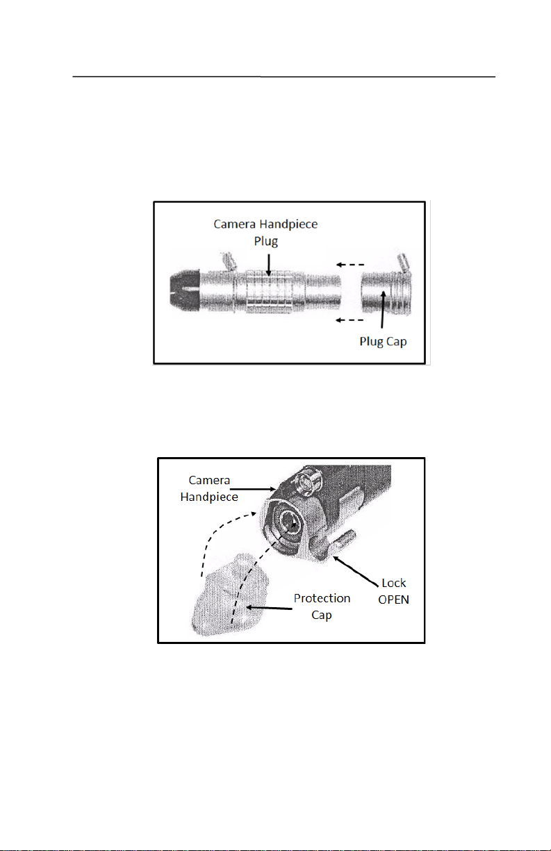
Visual Guide Interface
The camera handpiece provides alignment and a locking
mechanism for the camera handpiece- visual guide interface.
When the camera handpiece is not attached to the visual guide, a
protection cap is locked into place.
Page 5 of 49

DirectVision® Technical Reference Manual
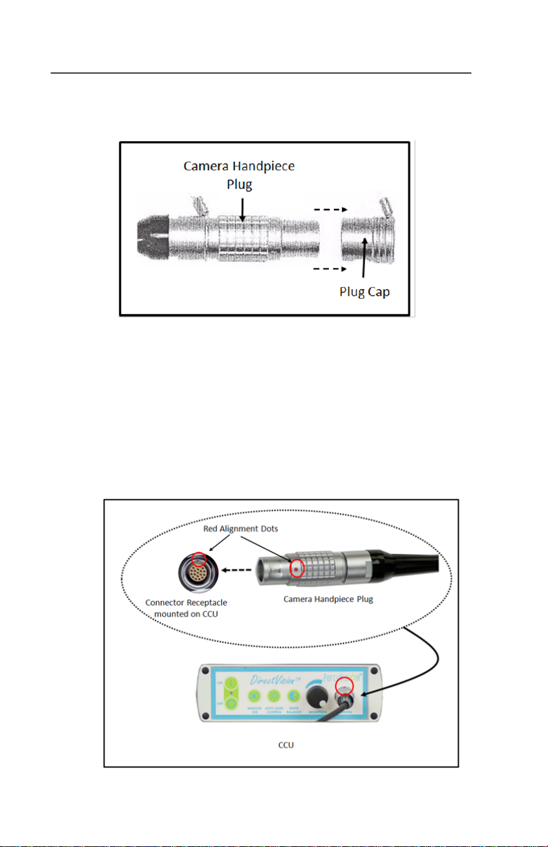
Camera Control Unit Interface
A shielded cable attached to the camera connector plug provides
the wired electrical interface between the Camera Control Unit
(CCU) and the camera handpiece. When plugging the camera
connector into the CCU, use the red dots on the camera connector
and CCU receptacle to align the recessed connector pins for
proper insertion.
Caution: Be careful how you align the Camera Handpiece Plug into
the CCU Connector Receptacle. Failure to align pins with the
corresponding pin hole could cause damage to the pins.
Page 6 of 49
DirectVision® Technical Reference Manual
Storage during Transportation
When the camera handpiece is not in use,
1. The wired attached Plug Cap is locked to the Camera
Handpiece Plug. The Plug Cap protects the receded gold
connector pins.
2. Protection cap is locked into place. The cap protects the
front glass of the LED light source and camera from
accumulating dust. It also protects the outside rim of the
lock mechanism of the handpiece from damage.
3. The handpiece is stored in the cart storage drawer.
Page 7 of 49
DirectVision® Technical Reference Manual
Camera Control Unit
The Camera Control Unit (CCU) provides power and control signals
to the camera. It converts video signal received from the camera
to several standard output video formats for video display. It also
provides the power for the LED light source.
The CCU is permanently mounted to the cart. Power and video
cables are pre-connected to the CCU. It is powered by a 12 VDC
medical grade power supply which is housed under the top tray of
the cart. It utilizes an LED to indicate the power ON state.
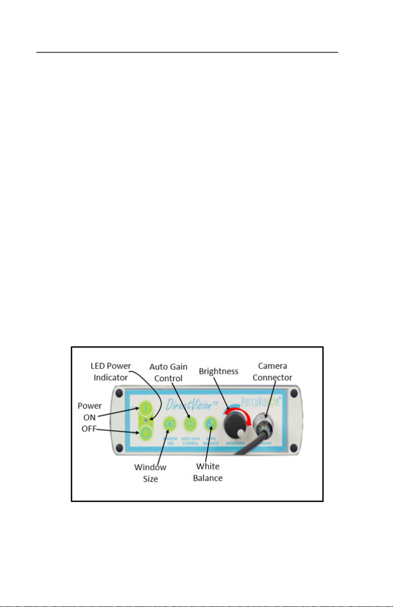
Front Panel Controls
The front panel of the CCU provides the following controls:
• ON/OFF switch
• LED Power Indicator
• Window Size
• Auto Gain Control
• White Balance
• Brightness adjustment
• Camera Connector
Page 8 of 49

DirectVision® Technical Reference Manual
Electronic Interfaces
The rear of the CCU provides interfaces for:
• Power (IN) 12 VDC
• RS 232 ( for internal service use)
• S-Video (OUT)
• Composite Video (OUT)
• USB 2.0 (OUT)
• FUSE
Page 9 of 49

DirectVision® Technical Reference Manual
Color Monitor Display
The color monitor display is a 17” high resolution LCD monitor. It is
mounted on a swivel bracket on the cart which enables easy
viewing angle adjustment. The monitor is powered by a 12 VDC
medical grade power supply located under the top tray.
LED Indicator
The LED Indicator provides the current power state of the
monitor. It is located in front at the lower right corner of the
Monitor screen bezel. It can display two colors: GREEN indicates
the Power ON State and a video signal is received. ORANGE
indicates that the monitor is in either the Power Saving State or
No Video Signal State.
Page 10 of 49

DirectVision® Technical Reference Manual
Control Dial
The Control Dial is a multi-functional device located behind the
LED Indicator on the right side of the front bezel. It has three
movements: rotate upward, rotate downward and press inward
as a button.
Monitor Power ON/OFF
Press the Control Dial inward to power the Monitor ON. To turn
the Monitor power OFF, press the Control Dial inward and hold for
at least 1 second until the LED turns off.
Menu Control
While the monitor is ON (i.e. Green LED and image on the screen),
press the Control Dial inward to activate the monitor menu
system. When the menu system is active, use the three-way
movement of the Control Dial to adjust the monitor:
• Rotate Downward: Move Down/Right, Increase
• Rotate Upward: Move Up/Left, Decrease
• Button Press: Execute, Do, Save
Page 11 of 49

DirectVision® Technical Reference Manual
Main menu selections for the Display Monitor are:
• Color
• Picture
• Auto
• OSD Menu (On Screen Display)
• MISC
• Exit
A plastic cover on the left side of the monitor screen hides the
cable connectors. Upon removal of the cover, the following cable
connectors are exposed:
• Power (IN) 12 VDC
• VGA Video (IN)
• Composite Video (IN)
• S-video( IN)
Note: the two monitor connectors used by the DirectVision®
System are: Power(IN) 12VDC and Composite Video (IN).
Page 12 of 49

DirectVision® Technical Reference Manual
Cart
The cart is mobile and features a small footprint. It is easily
moved from one patient location to another.
Workspace
The cart features a 15½“ x 21” work space integrated with two
steering handgrips.
Storage Area
There are three storage drawers, two of which are lockable. Keys
are provided.
Swivel Arm
A swivel arm bracket in the back of the cart houses a camera
handpiece holder and a telescoping IV pole. The camera
handpiece holder serves as a temporary holder of the camera
handpiece when the camera handpiece is being prepared to be
connected to the visual guide.
Power
Two medical power supplies are housed beneath the top tray, one
for the Camera Control Unit and the other for the display monitor.
Page 13 of 49

DirectVision® Technical Reference Manual
Height Adjustment
A yellow gas spring height adjustment lever enables positioning of
the monitor to a height for comfortable use.
Casters
The cart features four, 4 inch casters: two locking casters, one
swivel caster and one tracking caster. The locking casters are the
rear two wheels. During the catheterization procedure, the rear
two casters must be locked to prevent cart movement. The lock
levers for these wheels are gray.
The right front wheel is a tracking caster. It serves as a steering
wheel when the cart is moved. The lock lever for this wheel is
black.
Page 14 of 49

DirectVision® Technical Reference Manual
Power Cord
The cart’s power cord is 18 feet in length with a hospital-grade
power plug. The power cord is wrapped around two hooks
positioned on the cart’s adjustable column. The power cord plug is
placed on the hanger, which is located above the power cord
hanger. The cart must be plugged into a hospital-grade receptacle
for proper grounding. Proper grounding is essential for safety and
reliable operation.
Page 15 of 49

DirectVision® Technical Reference Manual
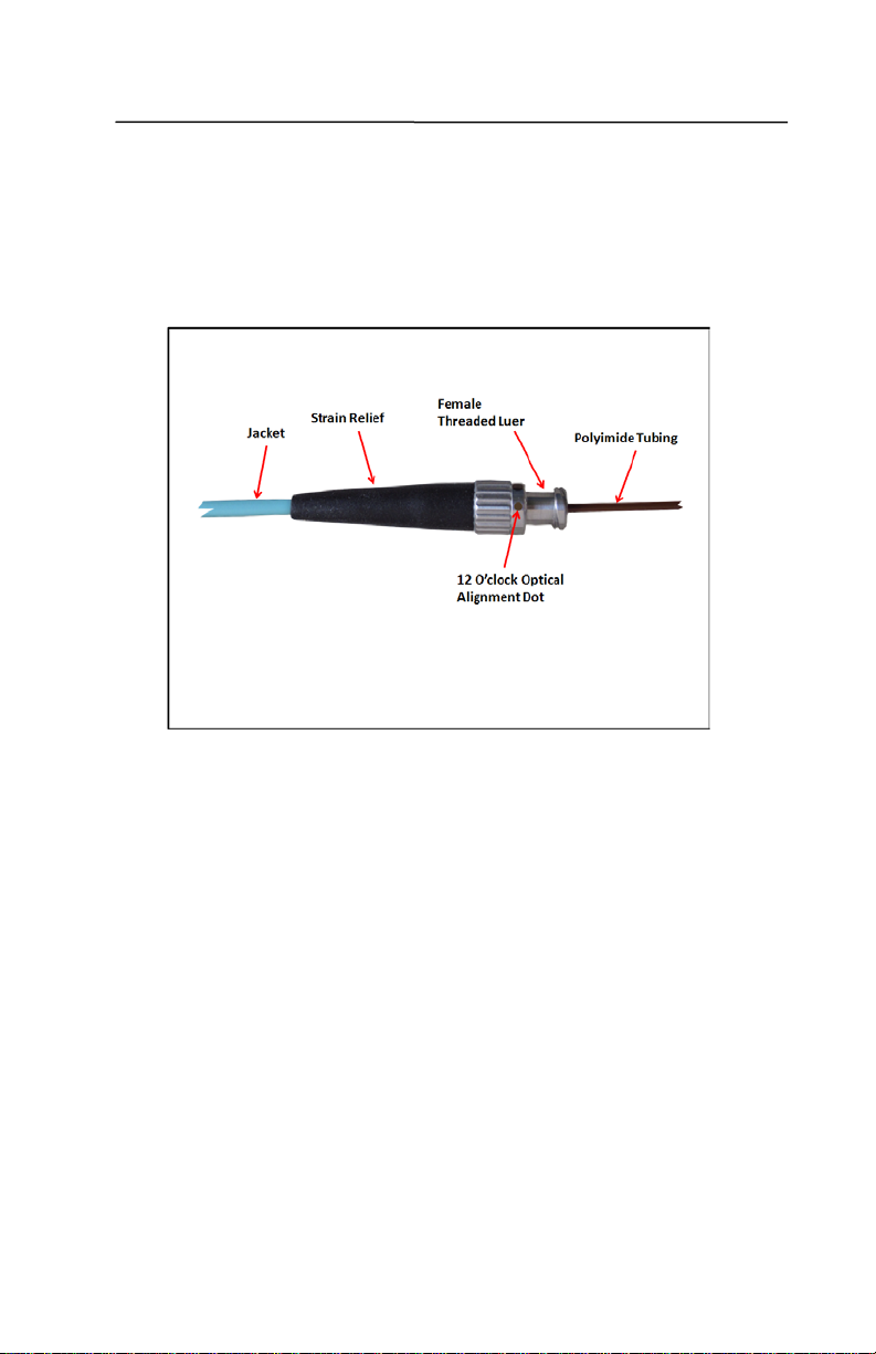
DirectVision® Guide
The DirectVision® Guide is a fiber optic element which transports
light and video information between the distal tip of the fiber
optic element and its proximal end. It consists of two fiber
channels encased in a sub-milimeter diameter polyimide sleeve.
One channel carries illumination light. The other channel carries
the video image.
Features
The visual guide is designed with a sleeve ridge (Internal Stop)
which abuts to a retaining wall in the catheter to stop the visual
guide from extending beyond the distal tip of the catheter. The
DirectVision® Guide is securely connected to the DirectVision®
Catheter by a Catheter Hub Lock. The camera handpiece is locked
to the visual guide by the handpiece’s locking swing arm.
Page 16 of 49
DirectVision® Technical Reference Manual
Optical Alignment Dot
The visual guide has an alignment “dot” on the female threaded
luer. This “dot” assists in locating the 12:00 o’clock position of the
visual guide.
Page 17 of 49

DirectVision® Technical Reference Manual
DirectVision® Catheter
The DirectVision® Catheter is a 3-lumen, 100% silicone, Foley
catheter that comes either uncoated or with water activated
lubricious coating. The first lumen is used for irrigation and
drainage. The second lumen is used for balloon inflation and
deflation. The third lumen is used to insert and remove the visual
guide
Page 18 of 49

DirectVision® Technical Reference Manual
Features
Balloon
The balloon is 10cc and is inflated with no more than 10cc sterile
water using a needleless syringe.
Angled Tip
The distal tip is angled (similar to a Coud
insertion.
é catheter) to facilitate
Retainer
The catheter has a built-in retainer to prevent the visual guide
from extending beyond the distal tip of the catheter.
Index Marks
Graduated index marks on the catheter shaft assist the user to
judge catheter penetration distances.
Page 19 of 49

DirectVision® Technical Reference Manual
Catheter Manifold
Tip of catheter is
curved up
Catheter dot
aligned to 12 O’clock
Catheter Alignment Dot
The alignment “dot” on the catheter manifold is on the same
plane as the angled tip. When the “dot” on the manifold is in the
12:00 o’clock position, the catheter tip is in the 12:00 position and
the catheter tip is curved up.
Catheter and Visual Guide Alignment Dots
When initially inserting the catheter, the “dot” on the visual guide
luer fitting and the “dot” on catheter irrigation/drainage port
should both be aligned to 12:00 o’clock position. This alignment
orientation ensures the tip of the catheter is pointing up and
orients the relative position of the image displayed on the monitor
to the 12:00 o’clock position.
Page 20 of 49

DirectVision® Technical Reference Manual
!
Initial System Assembly
Required Components
• DirectVision® System in its shipping box
• Color Monitor in its shipping box
• Camera handpiece
Required Hardware and Tools
• 4 Phillips head mounting metric screws (M4, 12mm)
• 1 Phillips #2 screw driver
Note: The DirectVision® Guide is not required for assembly and/or
to verify basic operation for DirectVision® System.
Initital Assembly & Test
1. Unpack and inspect shipment.
• Unpack cart from its shipping crate. With assistance, lift
the cart from the packaging riser.
Caution: Do not lift the cart by the tray or tray
handgrips. This action could result in damage to the
cart.
• Hold the cart by the base and support the sides as you
lift it.
Warning: The cart is heavy (about 140 pounds). Do not
lift the cart from the packaging riser without assistance.
Use proper lifting techniques when lifting heavy objects.
• Inspect the cart for shipping damage.
• Unpack color monitor from its shipping box
• Inspect the color monitor for shipping damage.
• If damage is identified, contact PercuVision®. Do not
assemble.
Page 21 of 49

DirectVision® Technical Reference Manual
2. Mount and connect power and video cables to monitor.
• Locate four (4) mounting screws in an envelope in the
top drawer
• Use Phillips #2 screw driver and 4 (M4, 12mm)
mounting screws to secure the monitor to the cart’s
monitor bracket.
• Facing the front of the monitor, remove plastic cover
located on left rear side of the monitor to expose the
power and video connectors.
• Connect the input power plug from the cart to the
display monitor.
• There are two input BNC video connectors on the
monitor. Connect the video cable from cart to display
monitor’s upper video BNC connector.
Page 22 of 49

DirectVision® Technical Reference Manual
• Replace plastic cover.
3. Plug in camera handpiece to CCU.
• Retrieve the camera handpiece from storage drawer of
cart.
• Place the camera handpiece into camera handpiece
holder located on the Swivel Arm.
Page 23 of 49
DirectVision® Technical Reference Manual
• Remove the metal Plug Cap from camera handpiece
connector.
• Attach the camera handpiece plug to the camera
connector receptacle on the CCU’s front panel. Use red
dots on the camera connector plug and the Connector
Receptacle on the CCU for proper plug alignment.
Caution: Be careful in how you align the Camera
Handpiece Plug into the CCU Connector Receptacle.
Failure to align pins with the corresponding holes could
cause damage to the pins.
Page 24 of 49

DirectVision® Technical Reference Manual
• Remove the Protection Cap from the camera handpiece.
3. Turn on power and verify correct basic operation.
• Remove the cart’s power plug from its holder on the
cart. Unwrap the power cord then plug it into a
110/120 VAC wall receptacle.
Page 25 of 49

DirectVision® Technical Reference Manual
• Turn on the Monitor power by pressing in on the
Control Dial on the right side of the monitor. The
monitor’s LED Indicator should be illuminated ORANGE,
indicating that the power is ON but no video signal is
received. If the LED Indicator is not illuminated, go to
the Troubleshooting Section of this Manual .
• Perform Monitor Setup Procedure. For details see
Monitor Setup Procedure Section of this Manual.
• Turn on CCU power by pressing the Power ON Button.
CCU LED turns ON.
Page 26 of 49

DirectVision® Technical Reference Manual
• The color of the monitor’s LED Indicator changes from
ORANGE to GREEN, indicating a video signal is being
received.
Note: The word PercuVision appears briefly on the monitor,
each time the CCU power is turned on.
• Verify that a video image appears on the monitor and the
tip of DirectVision® Guide is illuminated. Go to the
Troubleshooting Section of this Manual if no video appears
on the monitor or no illumination appears at the tip of the
DirectVision® Guide.
Page 27 of 49

DirectVision® Technical Reference Manual
• Turn the CCU off by pressing the Power OFF Button. LED
should turn off.
4. Return camera handpiece to cart storage drawer.
• Place the plastic Protection Cap on camera handpiece
and lock it into position.
Page 28 of 49

DirectVision® Technical Reference Manual
• Remove the Camera Handpiece Plug from the camera
Connector Receptacle on the CCU’s front panel.
• Attach Plug Cap to camera handpiece connector.
• Place camera handpiece into cart storage drawer.
Page 29 of 49

DirectVision® Technical Reference Manual
5. Prepare DirectVision® System for next use.
• Remove the 110/120 VAC cart plug from wall receptacle
then return it to its holder on the cart.
• Stock the cart drawers with inventory in accordance to
Cart Stocking Section of the DirectVision® Instruction
Manual.
• Place the DirectVision® System in holding area, waiting
to be used.
• Operation of the DirectVision® System has been verified
and is now ready for use.
Page 30 of 49

DirectVision® Technical Reference Manual
Monitor Setup
Control Dial Definitions
The Control Dial on the right side of the monitor provides control
to navigate and select menu entries. The main menu is invoked
when the Control Dial is pressed in momentarily (i.e. < 1 second).
When the Control Dial is rotated UP or DOWN and the menu is
active, the position of the menu item to be selected is
incremented or decremented by one. Pressing the Control Dial in
monentarily causes the viewed item to be selected. Selected items
can be either a menu item or a setup parameter. Parameters
become stored and effective upon exiting the main menu.
Monitor Default Values
Initially set the monitor parameters to PercuVision®
recommended values. Only two parameters need to be changed
from the factory default values.
• Black Level = 70
• Video Source = Composite
The Black Level can only be set when video is detected (LED =
GREEN). The Video Source can be assigned to Composite
independent of the Video Detect State (LED = ORANGE or LED =
GREEN). If for some reason the display monitor becomes
suboptimal, reset the monitor to default values and then define
video source to be Composite and increase Black Level to 70. If still
suboptimal, call customer support.
Page 31 of 49

DirectVision® Technical Reference Manual
Main
Menu
Sub
Menu
PercuVision®
Recommend
Contrast
80
80
Brightness
50
50
Black Level
50
70
Color Temp
Neutral
Neutral
Exit
H-Position
50
50
V-Position
50
50
Phase 0 0
Clock
50
50
Exit
Exit
Language
English
English
OSD H. Pos.
50
50
OSD V. Pos.
50
50
Exit
Source
VGA
Composite
Recall
Yes
Yes
Volume
50
50
Exit
Exit
Monitor Default Parameter Values
Default
Color
Picture
Auto
Auto Setup Yes Yes
OSD
Menu
Misc.
Page 32 of 49

DirectVision® Technical Reference Manual
Window
Size
Auto Gain
Control
White
Balance
Brightness
Camera Control Unit Calibration Procedures
Preconditions
The calibration procedures described in this section require the
following preconditions:
• The cart power cord is plugged into a 110/120 VAC wall
receptacle.
• The CCU and Display Monitor power switches are in the ON
position.
• The camera handpiece is plugged into the CCU.
• The camera handpiece is securely locked to visual guide.
Camera Control Unit Front Panel
Refer to the diagram below during the calibration procedure for
button control definitions
Page 33 of 49

DirectVision® Technical Reference Manual
Procedures
There are four calibration procedures for the CCU:
• Window Size
• Auto Gain Control
• White Balance Adjustment
• Focus
Each procedure is described in this section. Factory default
settings are provided where appropriate.
Window Size
The Window Size Button controls what part of the image seen by
the camera chip will be used for controlling camera sensitivity.
One of four different window presets can be selected.
1. Press the Window Size Button sequentially four times.
Windows 1 through Window 4 will be displayed.
2. Cycle through the four windows. Stop at the window which
produces the best optimized image on the monitor display.
3. Wait about 4 to 5 seconds. The Window Display on the
Monitor Display should disappear.
4. The size for the last window displayed is stored.
5. The selection in the last window displayed is used to
optimize the image displayed on the monitor.
Page 34 of 49

DirectVision® Technical Reference Manual
Default Factory
Setting
Window 1
Window 2
Window 3
Window 4
Default
Available
Choices
Default
Factory Setting
AGC-MAX 00 dB
AGC-MAX 10 dB
Default
AGC-MAX 12 dB
CCU Button Available Choices
Window Size
Auto Gain Control
The Auto Gain Control Button activates three different factory
presets. These presets affect the color and contrast of the image.
Toggle through these presets until you are satisfied with the
picture on the monitor screen.
1. Press the Auto Gain Control Button.
2. The monitor screen will display one of the following
settings:
• AGC-Max 00db
• AGC-Max 10db (Default)
• AGC-Max 12db
3. Push the Auto Gain Control Button once for preset no. 1,
again for preset no. 2, again for preset no. 3 and again to
return to preset no. 1.
4. Cycle through the three choices. Stop at the screen which
produces the best optimized image on the monitor display.
5. Wait about 4 to 5 seconds. The Window Display on the
Monitor Display should disappear.
6. The last preset view is stored until CCU powered off.
CCU Button
Automatic Gain
Control
Page 35 of 49

DirectVision® Technical Reference Manual
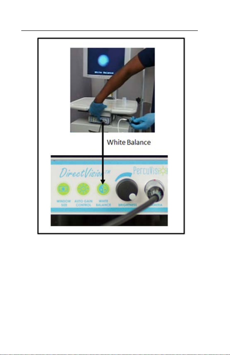
White Balance Adjustment
To adjust the white balance, proceed as follows:
1. Aim the illuminated tip of the catheter with the
DirectVision® Guide inserted into the visual guide lumen or
the visual guide tip itself to within approximately 5mm of a
white object.
If the monitor background color appears red or blue or green,
press and release the WHITE BALANCE Button on the CCU to
correct the background color.
Page 36 of 49

DirectVision® Technical Reference Manual
White Balance text string will appear on monitor screen as the
CCU begins executing the white balance operation. When the
white balance operation is completed, the text string changes to:
White Balance OK. The image will change to an accurate white.
The white balance operation enables the camera to reproduce all
colors in a natural tone.
Page 37 of 49
DirectVision® Technical Reference Manual
Page 38 of 49

DirectVision® Technical Reference Manual
Focus
1. Point the illuminated tip of DirectVision® Guide to within
approximately 5 mm of a white object with text.
2. Observe and assess video image sharpness (e.g. especially
vertical and horizontal lines) on display monitor.
Page 39 of 49
DirectVision® Technical Reference Manual
3. Adjust the focus ring on the camera handpiece until the video
image is sharp.
System Maintenance
Camera Control Unit Fuse
1. Open the fuse holder with flathead screwdriver.
o
2. Turn the fuse holder 90
3. Exchange with proper fuse.
4. Close the fuse holder by turning it 90
counter-clockwise.
o
clockwise.
The DirectVision® System is designed to require no other
maintenance.
Page 40 of 49

Troubleshooting
Step #
Problem
Potential Solution
• Check to see if unit is plugged
• Cycle Power Switch on for
No image on Display
Monitor
1
No Power Light on CCU
No Power Light on
Display Monitor
DirectVision® Technical Reference Manual
into a working 110-120 VAC
socket
• Check different outlet
• Check cart extension cord
• Confirm two power supplies
are plugged into cart
extension cord (must remove
top tray of cart)
• Verify 12VDC output for two
power supplies
• Verify 12V cables are correctly
connected to CCU and Display
Monitor
• Check CCU Fuse
• Cycle Power Switch on for CCU
and Display Monitor
• Call Customer Service
No image on Display
Monitor
2
No Power Light on CCU
Power Light on Display
Monitor
CCU
• Check CCU Fuse
• Confirm CCU power supply is
plugged into cart extension
cord (must remove top tray of
cart)
• Verify 12VDC output for CCU
power supply
• Verify 12V cable is correctly
connected to CCU
• Cycle Power Switch on CCU
• Call Customer Service
Page 41 of 49

DirectVision® Technical Reference Manual
• Cycle Power Switch on
•
OFF
• Verify camera handpiece cable
Step # Problem Potential Solution
Display Monitor
• Confirm CCU power supply is
No image on Display
Monitor
3
Power Light on CCU
No Power Light on
Display Monitor
plugged into cart extension
cord (must remove top tray of
cart)
• Verify 12VDC output from
Display Monitor power supply
• Verify 12V cable is correctly
connected to Monitor Display
• Cycle Power Switch on
Monitor Display
• Call Customer Service
No image on Display
Monitor
4
5
Power Light on CCU
Power Light on Display
Monitor (ORANGE
color)
No image on Display
Monitor
Power Light on CCU
Power Light on Display
Monitor (GREEN color)
Turn CCU
• Verify Composite Video cable
is correctly connected
• Verify video source for the
Display Monitor is Composite
• Call Customer Service
is properly connected to CCU
and the cable has no defects
• Verify visual guide is properly
aligned and locked to camera
handpiece
• Increase the light intensity by
turning the dial to MAX
position on the CCU
• Call Customer Service
then ON
Page 42 of 49

DirectVision® Technical Reference Manual
• Verify camera handpiece cable
• Cycle Power Switch on for
• Verify there is light from
Step # Problem Potential Solution
is properly connected to CCU
No light from camera
6
7
Power Light on CCU
No light from camera
No Power Light on CCU
and the cable has no defects
• Increase the light intensity by
turning the dial to MAX
position on the CCU
• Call Customer Service
CCU
• Check CCU Fuse
• Confirm CCU power supply is
plugged into cart extension
cord (must remove top tray of
cart)
• Verify 12VDC output for CCU
power supply
• Verify 12V cable is correctly
connected to CCU
• Cycle Power Switch on CCU
• Go to Step 6
No light from
8
DirectVision® Guide
Power Light on CCU
camera
• Verify alignment and lock
between visual guide and the
camera handpiece
• Increase the light intensity by
turning the dial to MAX
position on the CCU
• Replace DirectVision® Guide
• Call Customer Service
Page 43 of 49

DirectVision® Technical Reference Manual
• Cycle Power Switch on for
Step # Problem Potential Solution
CCU
• Check CCU Fuse
• Confirm CCU power supply is
No light from
9
10 Blurred image
DirectVision® Guide
No Power Light on CCU
plugged into cart extension
cord (must remove top tray of
cart)
• Verify 12VDC output for CCU
power supply
• Verify 12V cable is correctly
connected to CCU
• Cycle Power Switch on CCU
• Go to Step 8
• Turn the focus ring on the
camera handpiece until the
image is in focus
• Clean the tip of DirectVision®
Guide
• Replace DirectVision® Guide
• Replace camera handpiece
• Turn the focus ring on the
camera handpiece until the
image is in focus
• Call Customer Service
11 Image is too dark
Page 44 of 49
• Increase the light intensity by
turning the dial on the CCU
• Re-adjust white balance
• Re-adjust Display Monitor
setting
• Replace DirectVision® Guide
• Call Customer Service

DirectVision® Technical Reference Manual
•
Color bands seen
• Replace camera handpiece
•
• Call Customer Service
Damaged
Step # Problem Potential Solution
Re-adjust white balance
12
Inaccurate colors
• Re-adjust monitor settings
• Call Customer Service
13
14 Poor Visibility
15
on monitor
Cannot Insert
DirectVision®
Guide into
catheter
• Call Customer Service
• Confirm all connections are
properly placed.
• Check monitor settings
• Check CCU settings (Refer to
CCU Calibration Procedures
Section)
• Confirm camera-visual guide
connection is free of debris.
• Check focus
• Replace visual guide
• Check focus
• Call Customer Service
Confirm you are using the
proper catheter.
• Confirm that the visual guide
channel is sufficiently
irrigated.
• Confirm visual guide is not
damaged
• Confirm catheter is not
damaged
• Try a new catheter
• Try a new visual guide
16
DirectVision®
Guide or
catheter
• Replace damaged item(s)
with new one.
• Call Customer Service
Page 45 of 49

DirectVision® Technical Reference Manual
21 x 63.5 x 18 inches
(533x1613x457mm) (W x H x D)
141.5 1bs (63.5 kg approx.)
Monitor
Parameter
Value
Power Supply Module: Input:
mains voltage
Power Supply Output:
12 VDC, max. 1.25 A
Power Consumption:
12 VA
Technical Specifications
Dimension & Weight
Camera Control Unit
Parameter Value
Dimension:
Weight: 2.641bs (1.2kg)
Monitor
Parameter Value
Dimension:
Weight: 17.6 lbs (8 kg approx.)
Cart
Parameter Value
Dimension
Weight
6.65 x 2.44 x 9.72 inches
(169x62x247mm) (W x H x D)
17 x 14.65 x 7.91 inches
(432x372x201mm) (W x H x D)
excluding weight of CCU and
Electrical Specifications
Camera Control Unit
Page 46 of 49
100-240 VAC, max 0.5A, 50/60 Hz

Monitor
Monitor Power Supply module:
Input mains voltage
Monitor Power Supply Output
Monitor Power Consumption
32 W (Typical)
2.5 W at power saving
Sensor Size
1/4” Charge Couple Device (CCD)
Detection
2:1 line interlacing
PAL: 752 (H) x 582 (V)
NTSC: 786 (H) x 494 (V)
PAL 625 lines,
NTSC 525 lines
Brightness
Automatic
Signal/Noise ratio
46dB
S-Video (Y/C)
USB 2.0
DirectVision® Technical Reference Manual
Parameter Value
100-240 VAC, max 1.5A, 50/60Hz
12 VDC, max. 5.0A
Monitor Power Consumption
38 W (maximum) at full
brightness
Camera Specifications
Parameter Value
TV System PAL or NTSC
Picture Elements
Resolution
Output signal
Composite Video (CVBS)
Page 47 of 49

DirectVision® Technical Reference Manual
Parameter
Value
Field of View
70 o
Direction of View
0 o
Optical Resolution
4.9 lp/mm at 5mm distance
50
o
F up to 104
o
F
(10o C up to 40
C)
Humidity
up to 90%
+41o F to +95o F
(+5o C to +35o C)
Humidity
20% to 80% RH
+59o F to +95o F
(+15o C to +35o C)
Humidity
30% to 90% non-condensing
Visual Guide Specifications
Operating Environment
Camera Control Unit and Camera Handpiece
Parameter Value
Temperature
Monitor
Parameter Value
Temperature
Cart
Parameter Value
Temperature
o
Page 48 of 49

DirectVision® Technical Reference Manual
Storage Environment
The DirectVision® System and its consumables are to be stored at
room temperature in a controlled environment.
Spare Parts
Camera Control Unit
Name Description
Main fuse T800, 250V, 5x20mm
Warranty, Service & Claims
Do not attempt to service this product or you risk voiding the
warranty.
Contact PercuVision, LLC at 1-877-913-6333
References
DirectVision® Instruction Manual, PL000013.
Page 49 of 49


PercuVision® LLC
2030 Dividend Drive
Columbus, Ohio 43228
877-913-6333
www.percuvision.com
PL000032 Rev 05
 Loading...