

Page 1
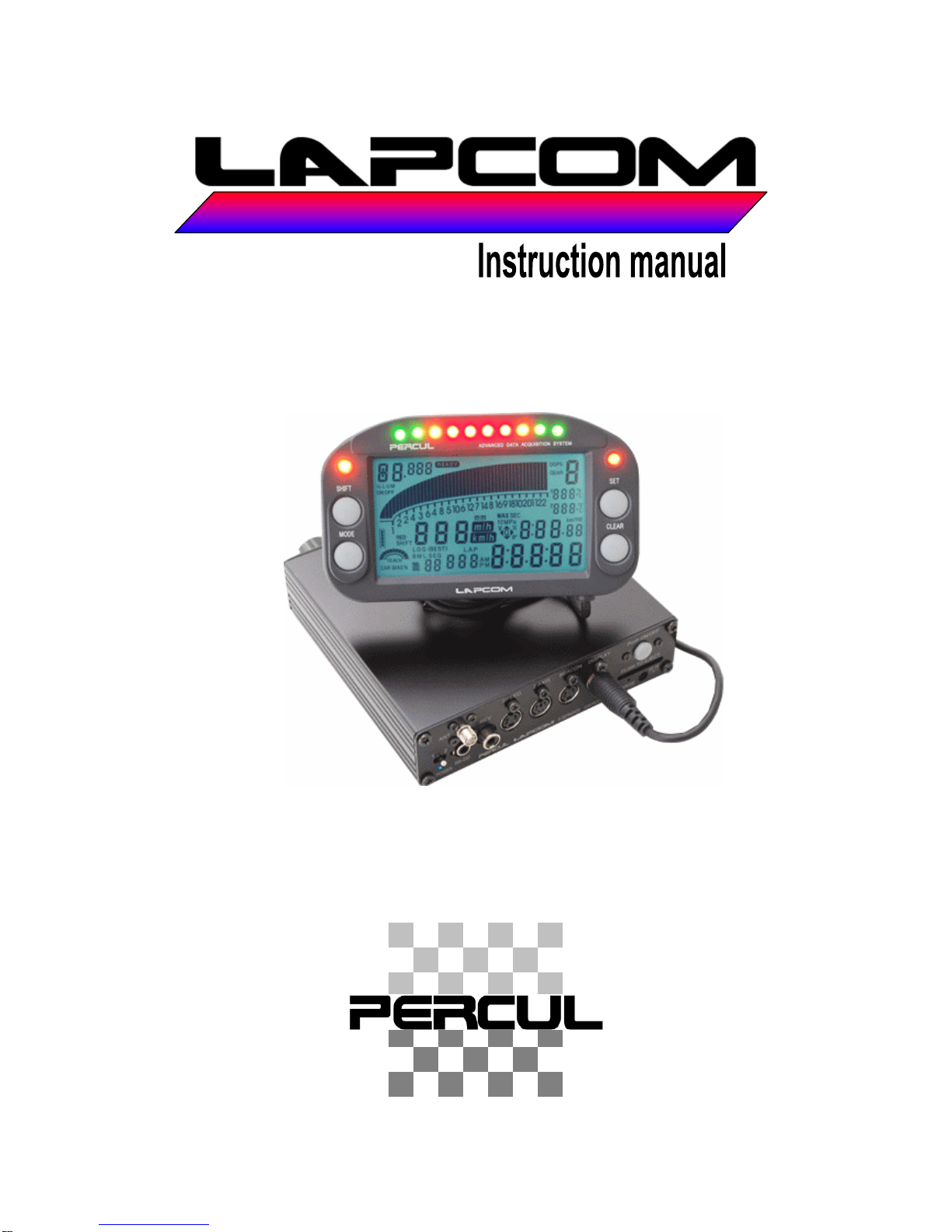
S Separate 100
Ver.1.1
Page 2
FOREWORD
Thank you for purchasing LAPCOM S Separate 100 and its related products. This product
is a racing vehicle measuring instrument that provides the following functions.
S Separate 100 Specification
Lap Memory 999Lap
Lap Timing Magnetic or Infrared
Split Times Up to 6 splits based on buried magnets
RPM Digital display
Wheel Speed Optional
Temperature 2ch. Optional
Steering, Throttle & Pressure Optional
Battery pack Nickel Metal hydrate standard (Rechargeable)
Battery Life 10 Hours approximate.
Quick charging Quick charging time 60 minutes with supplied charger. * Trickle
charging of 14-15 hours is recommended for full charge.
Hour Meter 5 engines’ running time hour meter. * This is available
when the RPM is measured.
Odometer Odometer. * This is available when the speed is measured.
Data Logging Data logging to a SD memory card for analysis. * Memory
card is required. Maximum 32G.
Shift lights Programmable
Temp Alarms Programmable
RPM Red line Programmable
Sampling rate 10 Hz or 20 Hz
Battery Alarm & Auto power
off
When the battery is running low, a "V" starts flashing on the
display and the power lamp will go out in about an hour due to
the auto power off function.
For your safety, observe the following
Warning Icons
Warning Ignoring this may result in death or serious injury.
Caution Ignoring this may result in injury or physical damage.
Alert Ignoring this may result in the disruption or suspension of function.
Attention
1. Copying all or part of this manual without permission is strictly prohibited.
2. The contents of this manual may not be modified without prior notice.
3. If you discover any errors, omissions, or any part that is unclear, we would appreciate your
advising us.
4. Percul Co. accepts no liability or responsibility for any outcomes resulting from user
operation, equipment failure, incorrect operation, or external factors.
5. The warranty is voided if any of these products is disassembled or modified without
permission.
-1-
6. Do not use this product except in a racing vehicle.
Page 3

-2-
CONTENTS
1) SAFETY INSTRUCTION for USE 3
2) Checking the Product 4
3) Names of Parts 5
Inserting and removing SD memory card 7
4) Charging the Instrument 8
5) Installation 9
1. Control unit 9
2. Display 10
3. Magnetic sensor 11
4. Pulse lead for RPM 12
5. Wheel speed sensor 13
6. Liquid sensor 13
7. Spark plug temperature sensor 14
8. Intake/exhaust air temperature sensor 14
9. G sensor 15
10. How to connect the external indicator & battery, and the cords 16
11. How to connect to the ECU wheel speed and rpm signal 17
6) Turning the Power On/Off 18
7) Setting of Parameters 19
<Changing the main unit to the parameter setting screen> 19
No.0: Date and time setting 20
No.1: Hour meter, trip meter, and odometer 21
No.2: Backlight 22
No.3: Number of Segments 23
No.4: Sensor Off Timer 24
No.5: Speed Pulse Length 25
No.6: Unit of Speed 26
No.7: Logging start/stop condition 27
No.8: REV Position 32
No.9: Information lamp and bar-graph full scale 33
No.10 & 11: Temperature Alarm 34
No.12 & 13: Pressure Alarm 35
No.14: Calibration for Steering movement 36
No.15: Calibration for Throttle position 37
No.16: Gear position 40
No.17: Logging interval 43
No.18: Baud rate 44
No.19: Time difference with previous lap, best lap, and target lap 45
No.20: Averaging number of speed and RPM data sampling 48
8) Saving and Transferring Parameter Settings 49
Saving the parameters in the main unit to the memory card 49
Transferring the parameters on a memory card to the main unit 50
9) Selecting the Data Item to Display During Driving 51
10) Monitoring Data during Driving 52
11) Reviewing Data from the Display 53
12) How to delete Driving Data 56
13) How to Initialize the Parameter Settings 56
Page 4
1) SAFETY INSTRUCTIONS for USE
-3-
- Do not disassemble or modify this device. Doing so could cause a fire, an
electric shock, or damage to the device.
- If anything unusual emanates from the device such as smoke or a strange
smell, immediately remove the plug from the power outlet.
- Remove the plug from the power outlet before conducting maintenance on
this device. Leaving it plugged in could cause an electric shock. Regularly
wipe dust from the plug. Leaving it for any length of time could result in fire.
- During thunderstorms, stop using the device, remove all cables from the
device and the plug from the power outlet.
Warning
- This device uses splash-proof construction. If it gets soaked it could cause a
fire or an electric shock.
- Do not touch the power outlet with wet hands, as this could cause an electric
shock.
- Do not modify the AC adapter, and do not bend, twist, damage, or apply heat
to any of the cables.
- Use only the indicated voltage. Doing otherwise could cause a fire or an
electric shock. When using other electric appliances together from the same
power outlet, ensure that the total electric current does not exceed the
circuit limit.
- Do not switch on the power to this device in the presence of inflammable gas
or fluids as this could cause a fire.
- Do not use this device where the use of such devices is prohibited.
- Use only the AC adapter supplied.
Caution
- Correctly insert the plug into the power outlet. Any metal that comes into
contact with the AC adapter plug could cause a fire or an electric shock.
- Pull the AC adapter plug from the power outlet by the body. Pulling it out by
the cord could cause a fire, an electric shock, or damage to the adapter.
- Before using these devices, read this User's Guide.
- During operation, any cables that come loose or any connections that
become unstable through vibration could cause a malfunction of this device.
Do not apply stress to any of the connector joints.
Alert
- Do not exceed the prescribed time limit when charging the internal battery.
- If the internal battery is completely discharged, it could cause extreme
deterioration of the battery's performance and loss of all the stored data in
the device.
Page 5
2) Checking the Product
No image
-4-
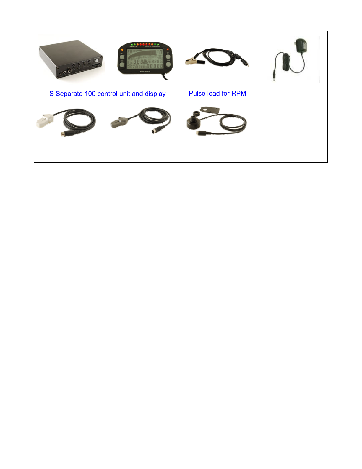
S Separate 100 control unit and display
Pulse lead for RPM
AC adapter
Magnetic sensor for kart
Magnetic sensor for car
High-sensitive OPT sensor
-Instruction manual
(this document)
Lap time sensor (Select one of the above.)
* If the high-sensitive OPT sensor is selected as the lap time sensor, the optional transmitter is required.
* The pulse lead can be replaced with the cable for ECU signal.
Page 6
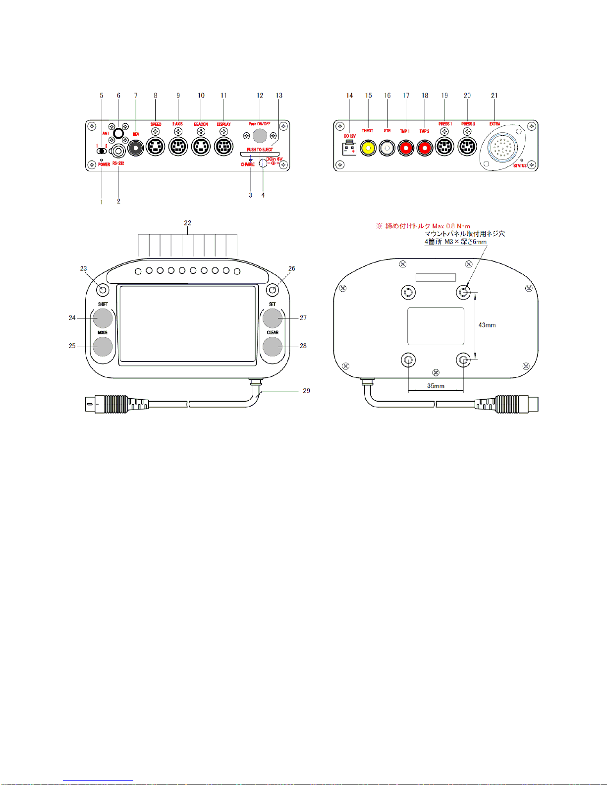
3) Names of Parts
<Display front>
1. Power lamp
It illuminates when the power of the unit is “ON”.
2. COM port
Connects various communication devices when using telemetry function.
3. Charging monitor lamp
It illuminates during rapid charging of the inner battery with the attached AC adapter.
4. Charging port
Connects the plug of the attached AC adapter.
5. Switch 1/2
It is used when saving the parameter setting in the unit memory into the SD card, and
vice versa.
6. GPS antenna port * This is available for only S Separate 100 Plus.
Connects GPS antenna.
7. REV port
Connects the pulse lead cable for RPM.
8. Speed port
Connects the speed sensor.
9. AXIS port
-5-
Connects the G sensor.
Page 7

-6-
10. BEACON port
Connects the attached laptime sensor.
11. Display port
Connects the attached display.
12. Power switch
It is used when operating the Lapcom with the inner battery. If the switch is ON and the
device is operated with the external DC12V power, the device will shift the operating
with the inner battery when the external power stops.
13. SD card slot
Inserts the SD card.
14. DC12V port
Connects the external battery connection cord (05841) when operation device with the
external DC12V power.
15. THROT port
Connects the optional displacement sensor.
16. STR port
Connects the optional displacement sensor.
17. TMP1 port
Connects various temperature sensors.
18. TMP2 port
Connects various temperature sensors.
19. Pressure1 port
Connects the optional pressure sensor.
20. Pressure2 port
Connects the optional pressure sensor.
21. EXTRA port * This is available for only S Separate 100 Plus.
Five analog channels input are available.
22. Information lamp
It illuminates as a shift lamp that informs the set shift timing for RPM.
23. Status lamp
It illuminates when the temperature or pressure drops below the set alarm value.
24. SHIFT key
It is mainly used when shifting to parameter setting screen or confirming each data. It
sometimes works with MODE key.
25. MODE key
It is mainly used when shifting to parameter setting screen or confirming each data. It
sometimes works with SHIFT key.
26. Status lamp
It illuminates when the temperature or pressure exceeds over the set alarm value.
27. SET key
It is mainly used when choose the setting values on the parameter setting screen.
28. CLEAR key
To return to the default screen from each screen mode, press this button.
Page 8
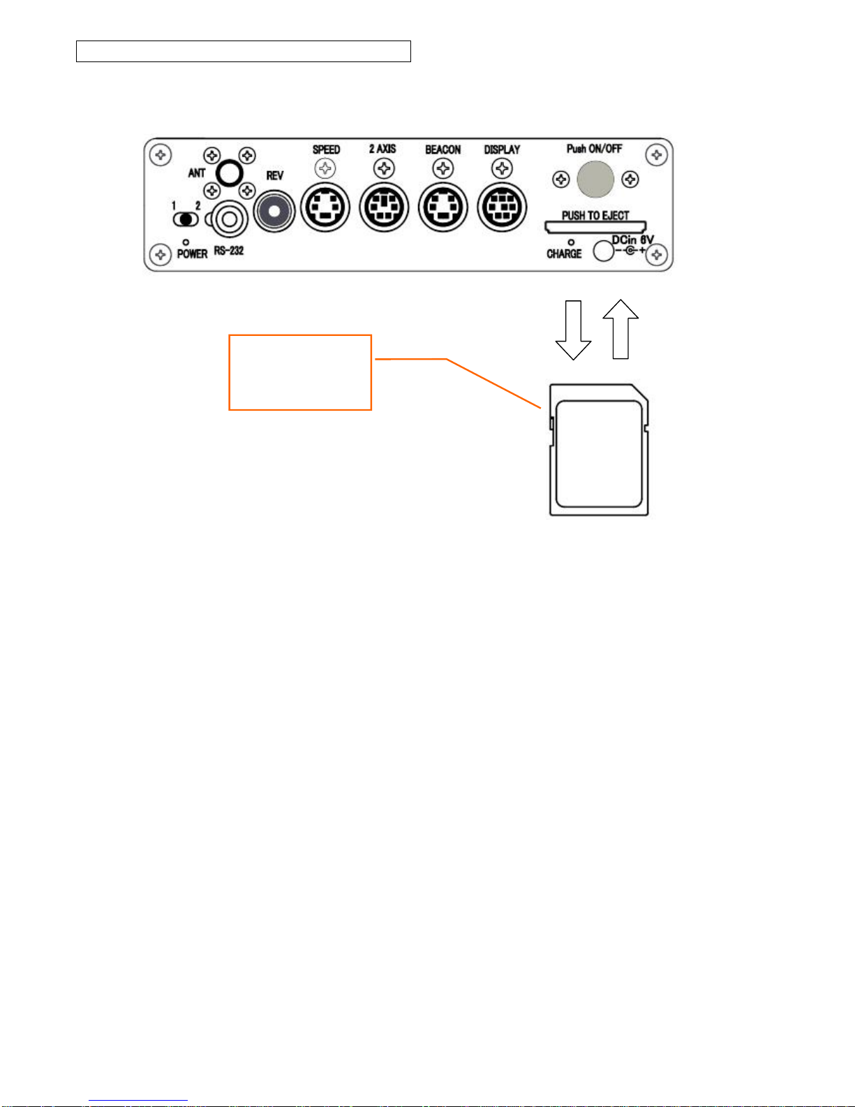
Inserting and removing a memory card
Memory card slot
Be sure to press the
CLEAR key before
removing the memory
card
* Only use reputable branded memory card, or the product may not operate correctly.
* If the label on the memory card is not recessed, the label can sticks on the edge of the
card slot and the card cannot be pulled out from the slot. We recommend that you use
type of card with recessed label.
1. Before inserting a memory card, first press the CLEAR key and verify that [READY]
is displayed.
2. Insert the memory card securely until a click sound is heard.
3. Before removing the memory card, first press the CLEAR key and verify that
[READY] is displayed.
4. Pressing on the memory card causes it to protrude slightly. When this occurs, simply
pull out the card.
* Before pulling out the memory card, be sure to press the CLEAR key and verify that
[READY] is displayed. If the memory card is removed without [READY] indication, the
data and/or the memory card may be damaged.
-7-
Page 9

-8-
4) Charging the Instrument
1. Be sure to turn the power of the unit off, and then insert the DC plug of the
provided AC adapter into the charging jack on the unit.
2. When the AC adapter is inserted into the outlet, rapid charging begins. (The
charging monitor lamp illuminates.) After rapid charging is completed (the charging
monitor lamp turns off), leave the battery connected for 2 – 3 hours for trickle
charging until the battery is fully charged. * Rapid charging alone will not fully
charge the battery.
* Before using the product for the first time after purchase, be sure to fully charge the
unit. Perform trickle charging for 14 - 15 hours after rapid charging ends, leave the
charging for 14 - 15 hours for trickle charging in order to fully charge the battery.
* If the battery temperature is higher than the temperature of the unit, a safety device
activates and charging cannot be started. Wait until the temperature of the battery
has fallen before beginning charging.
CAUTION: Be sure to observe the following in order to prevent deterioration of the battery.
●After rapid charging ends, do not leave the AC adapter connected to the unit for a long
period of time.
● Charge at a temperature of 5℃ - 35℃.
When the battery is fully charged, the unit can be operated for up to 10 hours. If the
battery power is low during use, the "V" comment on the display flashes, the automatic
power off function activates, and the POWER lamp turns off. Be aware that if the power
switch is turned on again before charging the battery, the automatic power off function
may not activate sometimes. As a result the battery may become completely discharged,
causing the data in the internal memory to be lost.
The battery voltage will be low after the product is just purchased or when the product has
not been used for a long period of time. Be sure to charge the battery before use. In this
case, some time trickle charging may continue without illuminating charging monitor lamp
before rapid charging begins. This is not a malfunction. If rapid charging ends quickly and
trickle charging begins even when the internal battery is low, and this occurs several times
in succession, turn on the power switch and discharge the battery after trickle charging for
approximately 15 hours. Repeat this process several times to reactivate the internal
battery.
<Important> After using the product, if it will not be used for a long period of time, fully
charge the battery before storing the product. Even when the unit power is off, the
battery is still consumed at a very slow rate. Be aware that if the product is left disused
for a long period of time, the battery may become completely discharged. Be sure to
charge the battery before using the product again.
The laptimes related data including the calendar information in the internal memory is
deleted after approximately 1.5 - 2 months from a fully charged unit status. Be sure to
charge the unit once a month to keep the data.
Page 10
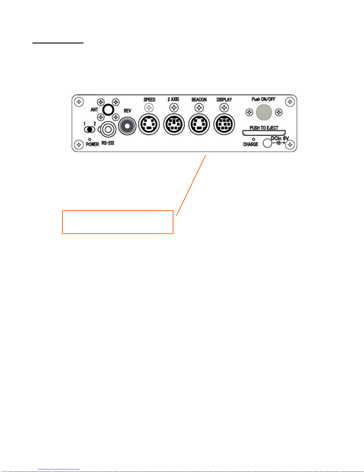
5) Installation
1. Control unit
1. Install the bottom of the unit by hook and loop fastener.
* Install the control unit where it will not interfere with driving.
Secure the bottom of the unit
by hook and loop fastener.
-9-
Page 11
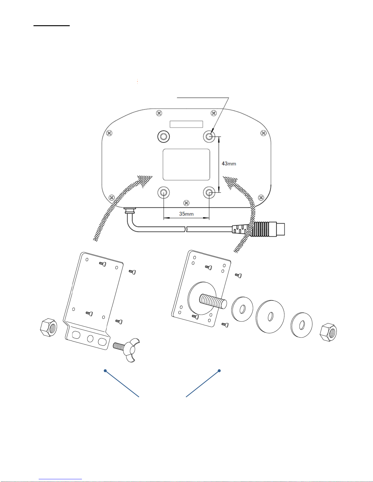
2. Display
1. Fasten the optional mounting panel onto the display using the 4 screws.
2. Install the mounting panel onto the steering wheel or instrument panel.
* Tightening torque Max 0.8 Nm
Threaded hole for installing mounting panel
4 spots M3 × depth 6 mm
T-typ
e mounting panel
F-t
yp
e mounting panel
Select one.
-10-
Page 12
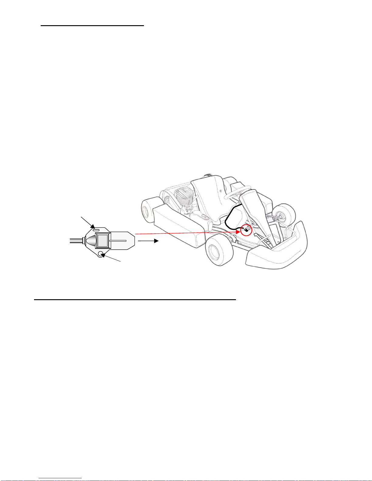
3. Magnetic sensor (for kart)
1. Use two-sided tape to attach the sensor on the floor panel. Attach so that the front of
the sensor points in the direction of forward travel. (Refer to the installation drawing.)
If you want to fasten the sensor securely in place, use M4 screws, tying bands, or
covering the sensor by vinyl tape. * The M4 screws and tying bands are not provided.
2. The sensor should be a minimum of 5 cm from any metal of main frame.
3. Connect the magnetic sensor connector to the LAP sensor port on the control unit.
At this time, verify that the power switch is off. If the power switch is on, the lap count
may start automatically, however this is not an error. Press the CLEAR key to stop
the count.
CAUTION: Position the sensor as far as possible from the ignition coil, plug cords, or
other items which generate a magnetic field.
Adjust the cables so that they do not contact the pulse lead.
-11-
<Sensitive Magnetic sensor (for 2 wheels or 4 wheels)>
1. Use two-sided tape to attach the sensor to the non-metallic part of the car body.
Attach so that the front of the sensor points in the direction of forward travel. If you
want to fasten the sensor securely in place, use M4 screws, tying bands, or
covering the sensor by vinyl tape. * The M4 screws and tying bands are not
provided.
2.
Install the sensor so that the height above the ground is 15 cm or less. The sensor
sensitivity varies depending on the type of magnets installed under the course. We
recommend to install the sensor as closer as possible to the ground without
interfering with safety mechanism on the vehicle.
3. Connect the magnetic sensor connector to the LAP sensor port on the control unit.
At this time, verify that the power switch is off. If the power switch is on, the lap
count may start automatically, however this is not an error. Press the CLEAR key
to stop the count.
Front or back
M4screw
Tie band
Page 13
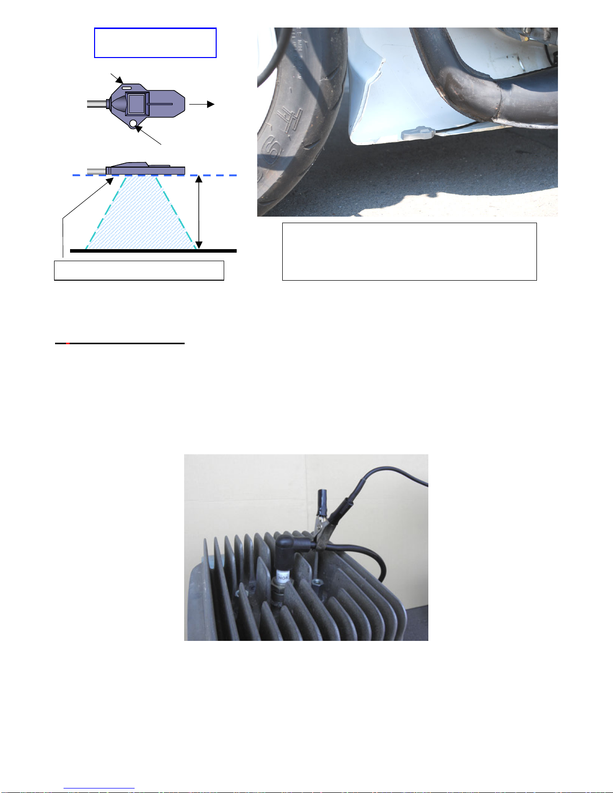
Sensitive Magnetic sensor
(for 2 wheels or 4 wheels)
Tie band
-12-
Sensing span
150 mm
or less
M4 screw
* It is possible to reverse the sensor.
Front or back
<Example of installation onto a minibike>
In the above photo, the sensor is installed horizontally
inside the under cowling of the motorcycle. * The photo
shows the under cowling opened.
4. Pulse lead for RPM
1. For Kart engines, replace the spark plug cap with a noise-suppressing product
(NGK LB05EMH or equivalent) or use a resistor spark plug.
2. Clip the lead to where RPM is correctly measured such as where all the plug leads
are gathered or the ignition coil lead.
3. Insert the pulse lead connector into the REV jack of the control unit.
CAUTION: The RPM pulse lead has not been soldered to the clip to help dampen
large engine ignition pulses that may enter the microcomputer of the control unit from
the RPM pulse lead. Direct connection will cause damage to the unit, ensure there is
no electrical contact between the cable and clip.
Page 14
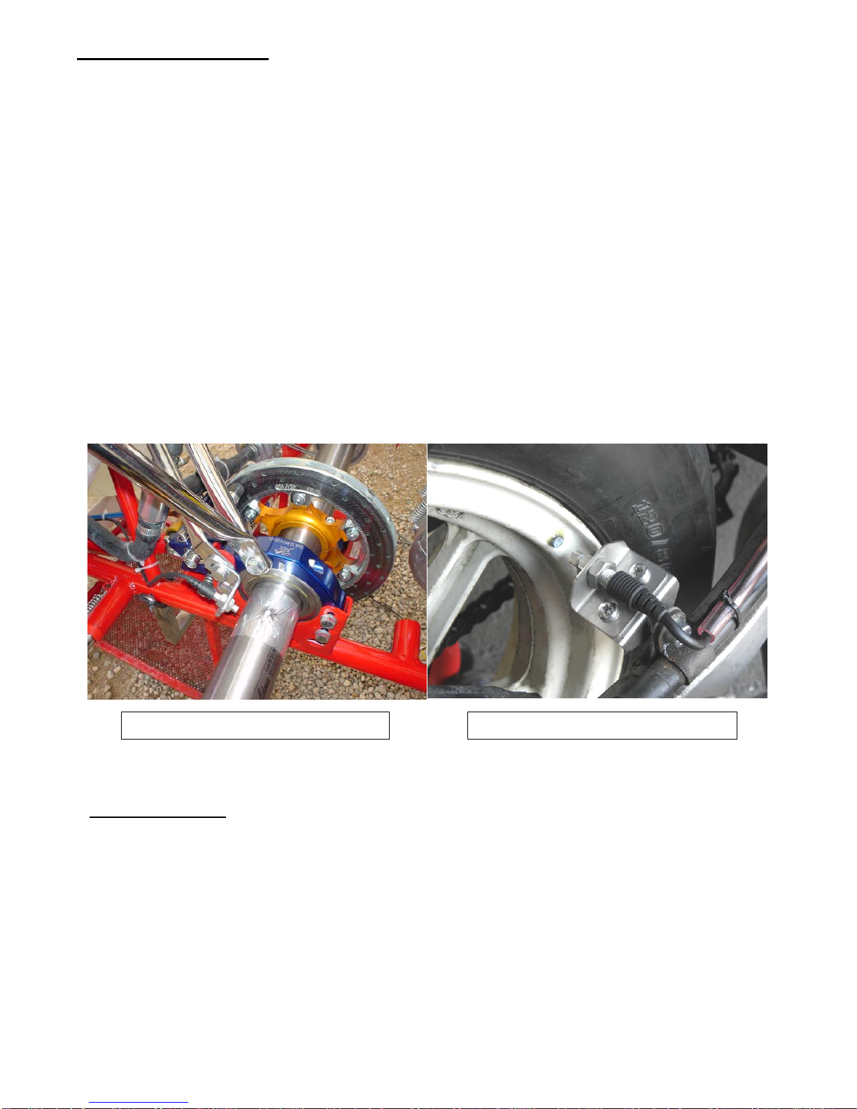
5. Wheel speed sensor (* The speed sensor is an optional part.)
1. Arrange the supplied magnet triggers around the axle or wheel. Usually 4 to 10
magnets are used. The speed pulse length (outer circumference of tire / number
of magnets) should be between 100mm and 999mm. Determine the number of
magnets to set the speed pulse length in this range.
2. Affix the magnets with tape. If you mount the magnets on the sprocket or wheel by
drilling holes, make sure that might reduce their strength.
3. Install the sensor bracket* on the place for ease installation of the sensor. (For
example, on the outside bearing hanger on the brake side of the chassis) Install
the wheel speed sensor so that the sensing surface is close to the magnets but
not touching them. Any touching would cause damage to the sensor. The distance
between the sensing surface and the magnets depends on the installation
condition, but a gap of 5mm or under is recommended.
4. Insert the wheel speed sensor connector into the speed sensor jack of the control
unit. *Wheel speed sensor bracket and screws are not supplied.
CAUTION: During installation, do not subject the upper resinous part of the sensor to
any stress by pinching or wrenching it with a tool.
Example of installation onto a racing kart Example of installation onto a motorcycle
6. Liquid sensor (* The liquid sensor and hose joint are optional parts.)
1. Cut the radiator hose and install the hose joint to connect the both edges of the cut hose.
2. Fasten the bands* the both sides of the hose joint. * These bands are not supplied.
3. Install the liquid sensor into the hose joint. Bend the spring/cable of the sensor
roundly like in the picture below. Fix the both side of the green connectors on the
radiator hose.
4. Fix the cable on the radiator side of the vehicle in several points.
5. Insert the liquid sensor connector into the TEMP sensor jack of the control unit.
CAUTION: Keep the sensor away from the engine head. It may occur an error due to the
engine noise.
-13-
Page 15
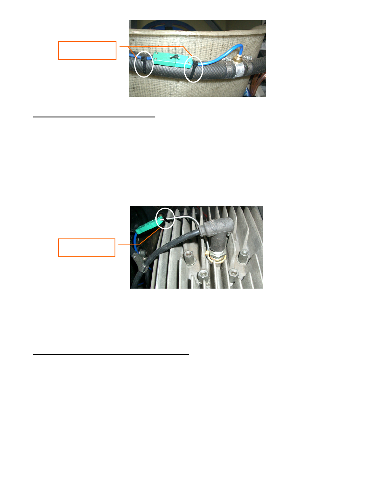
Fasten both sides o
f
the connector.
7. Spark plug temperature sensor (* The spark plug temperature sensor is an optional part.)
1. Remove the spark plug and ring.
2. Confirm if the sensor ring fits in the spark plug. Fit the sensor ring in the spark plug.
3. Place back the spark plug on the cylinder head and tighten the spark plug.
4. Make a hole in a cooling fin and fix the sensor spring through the hole. See the
picture below.
5. Insert the spark plug temp. sensor connector into the TEMP sensor jack of the
control unit.
-14-
Fasten the sensor
to the cooling fin.
8. Intake/exhaust air temperature sensor (* The intake/exhaust air temperature sensor is an
optional part.
)
1. Make a hole in the exhaust pipe. Weld a 1/8PT nut that should be the same metal
with the exhaust pipe. The nut for welding isn’t provided in the sensor kit. Please
provide the nut as per your exhaust requirement.
2.Mount the attached longer nut in the welded nut.
3.Mount the sensor and the attached shorter nut into the longer nut and adjust the
length of the sensor head.
4.Fasten the shorter nut to fix the sensor head.
Page 16
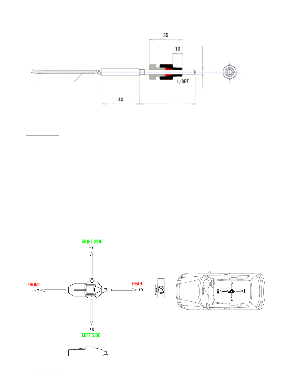
φ3.2 (special order item)
φ4.8 (standard item)
Stain mesh
(Order accepted per 5 mm, from 65 mm to 100 mm)
60 (standard item)
Cable length; 2000mm (standard item)
9. G sensor (* The G sensor is an optional part.)
1. Use two-sided tape to attach the sensor onto a location that is level in the
front/back and left/right direction. Attach so that the front of the sensor points in
the direction of forward travel. In order to fasten the sensor securely in place, use
M4 screws, tying bands, or covering the sensor by vinyl tape. * The M4 screws
and tying bands are not provided.
2. Refer to "Selecting the Data Item to Display During Driving" and verify the
front/rear and left/right G values. Even if the value shown on the display monitor
deviates slightly from 0.00, this will be corrected during driving. (The value at time
of shipment is 0.00 – 0.04.)
<If malfunction occurs when installed onto a racing kart or similar vehicle>
If the sensor is subjected to strong vibration, malfunction may occur. Place
low-repulsion urethane (sponge or similar) around the sensor to absorb vibration.
-15-
Page 17
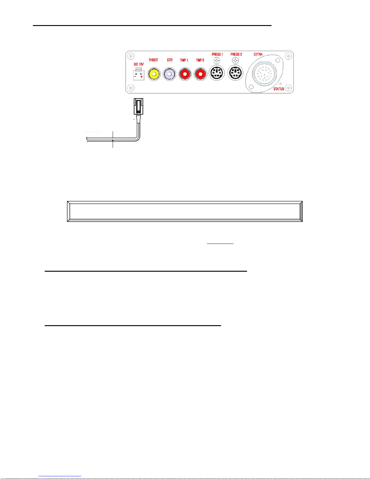
10. How to connect the external indicator & battery, and the cords
External battery
connection cord
DC12V Red (+)
* The current consumption is 50
mA when the external DC 12V
power is used. It is 100 mA when
the backlight is on.
1. Red: DC 12V (+)
2. Black: (-)
-16-
Precaution when operation in coordination with the ignition switch
If the ignition switch (LAPCOM main unit) is turned off while logging is in progress, the
logging data will be damaged. Therefore use both
1 and 2 below in order to prevent this
from occurring.
1.
Setting logging automatic end (parameters 7-1, 7-2, 7-3)
It is necessary to set so that logging is ended before the vehicle enters the pit and the
ignition switch (LAPCOM main unit) is turned off.
Or, press the CLEAR key to end logging manually.
2.
Operating in combination with a charged battery
At the instant when the ignition switch is turned off, the Lapcom main unit power
switches to the battery and continues operating.
1. Turn on the main unit power switch in advance.
2. Turn on the ignition switch.
Page 18

-17-
11. How to connect to the ECU speed and rpm signal
※ Each signal is a square wave (pulse).
[Precautions]
① The Lapcom control unit should be run by 12V external power supply.
② It is necessary to modify the Lapcom control unit to a dedicated ECU circuit.
③ Depending on the vehicle type and specifications, measurement may not be possible
in some cases.
④ If the vehicle has remodelled electrical system or added meters, it may not be able to
correctly take in signals from ECU.
⑤ When contacting us regarding ECU connections, please ready the ECU signal
explanation manual beforehand. We are unable to provide an answer based on the wiring
diagram alone.
[RPM signal]
1. Verify that the RPM signal is being output by the ECU.
If the voltage level of the RPM signal is low, the amplifier pulse lead (our optional
parts) is required.
※ If the RPM display is not stable, try to put resistance of 1-3 kilo ohm. This sometimes
makes the RPM stable.
2. Connect the red wire of the provided ECU RPM signal cable to the ECU RPM signal.
The voltage of the signal should be 4V to 12V.
3. Set the REV position of the control unit.
[Speed signal]
1. Connect the white wire of the provided ECU speed signal cable to the ECU speed
signal.
2. Check the speed pulse number, then calculate and enter the speed pulse length.
<4-wheel vehicle> 1,569.85 / Speed pulse number = Speed pulse length (valid:
100 or higher)
<2-wheel vehicle> 714.29 / Speed pulse number = Speed pulse length (valid: 100
or higher)
※ If the tire size has been changed from the genuine part size, multiply the above speed
pulse length by the tire diameter size increased rate and enter the result. Be aware that
depending on the vehicle, the above standard may not apply.
※ When the speed pulse number is 2 pulses, the use of the speed pulse converter (our
optional parts) is recommended.
※ If the speed pulse length is less than 100, it is possible to modify the control unit to
reduce the speed pulse number to 1/4. Please consult with us.
Page 19
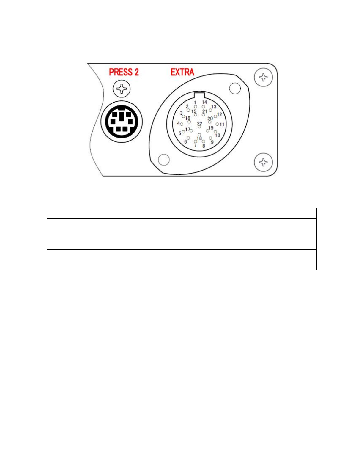
12. How to connect to EXTRA port
* This port is only available with S Separate 100.
1 Analog 1 0-5V 6 --- 11 Status lamp 2 illuminates 17 --2 Analog 2 0-5V 7 GND 12 Status lamp 1 illuminates 18 --3 Analog 3 0-5V 8 GND 13 NC13 19 --4 Analog 4 0-5V 9 NC9 14 NC14 20 --5 Analog 5 0-5V 10 NC10 15 GND 21 ---
16 NC16 22 ---
- LAPCOM side connector AS012-35SN
- Vehicle side connector AS612-35PN
6) Turning the Power On/Off
ON: Press and hold the power switch for 1 second.
OFF: Press and hold the power switch for 1 second.
-18-
Page 20
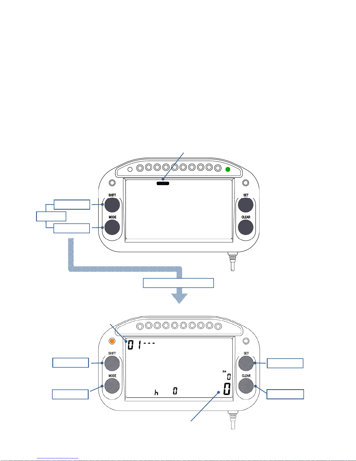
7) Setting of Parameters
<Changing the main unit to the parameter setting screen>
1. Verify that [READY] is displayed on the display screen. If [READY] is not
displayed, press the CLEAR key to display it.
2. Press and hold the SHIFT key and MODE key at the same time for 3 seconds to
change to the parameter setting screen. The parameter number is displayed at
the top left of the display.
3. Press the CLEAR key and set each parameter from No. 0 – 19 in sequence.
Press the MODE key to check the parameter No. settings in descending order.
4.
When the CLEAR key is pressed and held for 3 seconds, the settings will be
saved, the screen returns to the initial screen and [READY] is displayed.
READY
SHIFTキー
MODEキー
+
3 seconds
To the parameter setting
Parameter No.
SHIFTキー SETキー
SHIFT key
MODE key
SHIFT key
MODE key
SHIFTキー
SET key
CLEAR key
Primarily used to
change the flashing
location or digits.
Primarily used to ente
r
and select numbers.
Confirms the settings
and moves to the
next setting screen.
A
llows the settings
to be checked or se
t
in descending order.
Displays the current setting.
-19-
Page 21
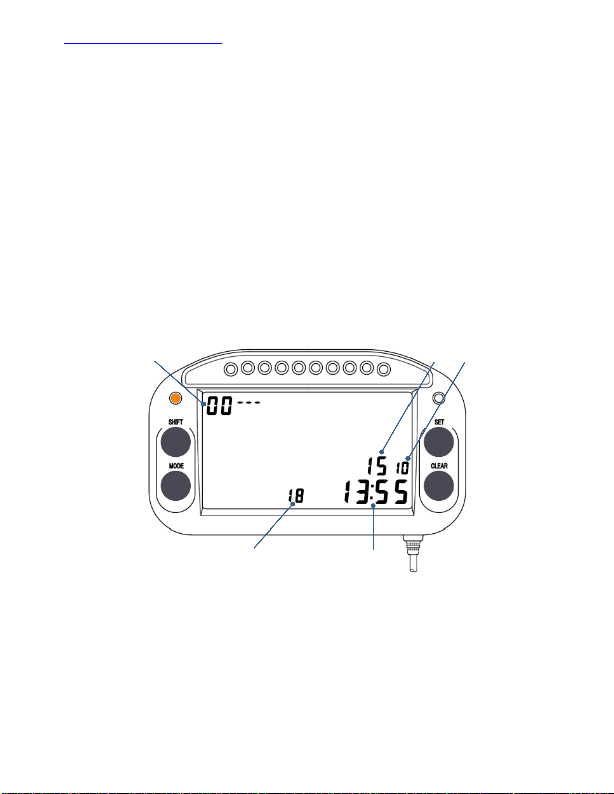
No. 0: Date and time setting
Set the current year, month, day, and time.
* The initial screen on the parameter setting is No. 1. To set No. 0, press the MODE
key.
1. The second digit of the year flashes. Press the SET key and enter a number.
2.
Pressing the SHIFT key changes the flashing digit to the first digit of the year. In
the same way, press the SET key and enter a number.
3. Use the same process to set the month, day, and time in sequence.
4. Press the CLEAR key to move to the next screen. To exit the setting, press and
hold the Clear key for 3 seconds.
* Only the last 2 digits of the year are displayed and set. The time is displayed in
24-hour format.
Setting example: 13:55, October 18, 2015
Time
Day
Year Month
Parameter No.
-20-
Page 22
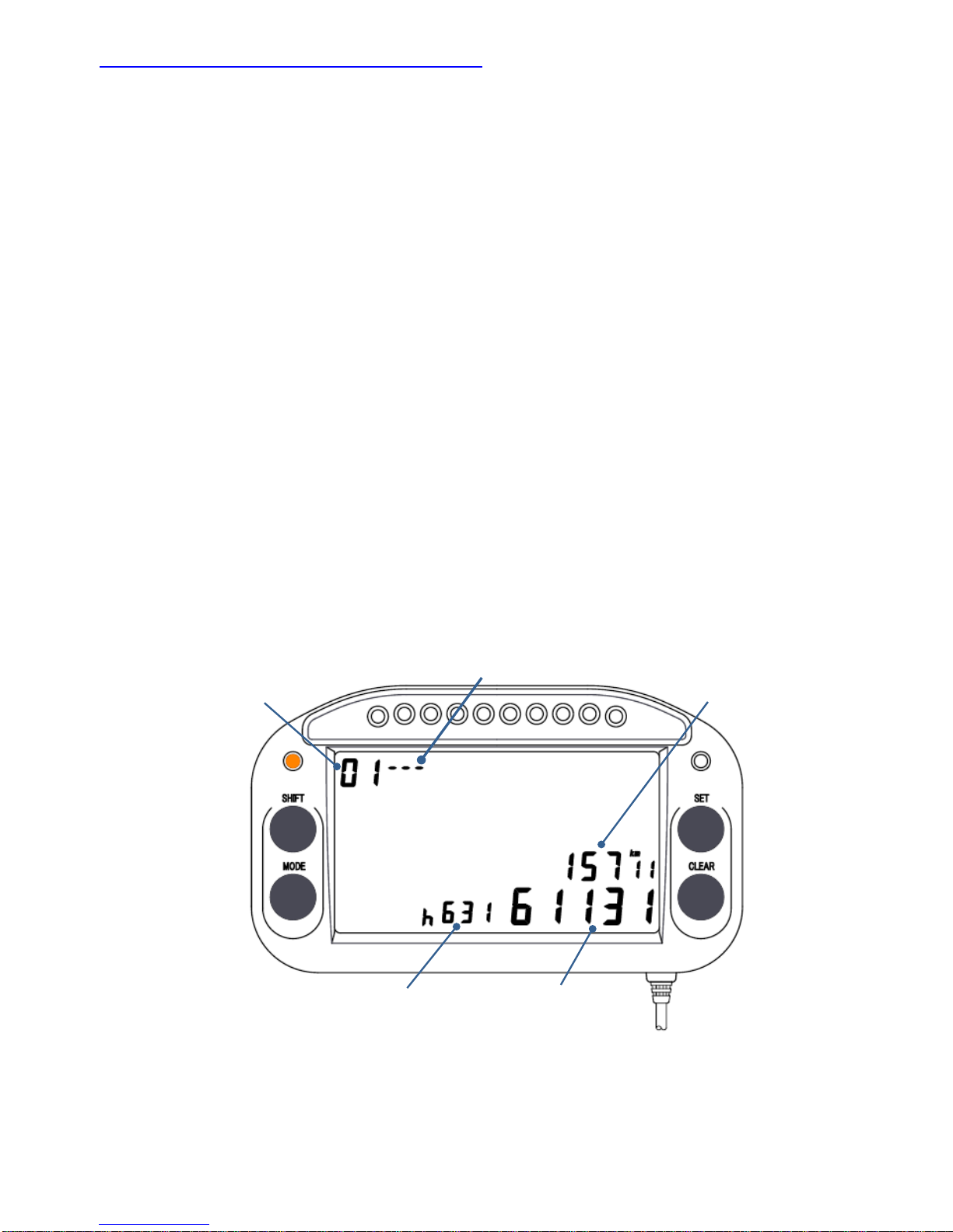
No. 1: Hour meter, trip meter, and odometer
Hour, trip, and odometer data can be recorded and displayed for a maximum of 5 types
of engines or vehicles.
* Press the CLEAR key and display parameter No. 1.
1. There is a flashing hyphen or number on the right side of the parameter No.
Press the SET key and enter the number of vehicle or engines to register. If the
displays will not be managed for different vehicles or engines, set a hyphen.
2. To reset the trip meter, odometer, and hour meter to zero, select on the display
the registered No. that you want to reset on the screen and press and hold the
SHIFT key for 3 seconds.
* On the “01---“ display screen, it is possible to reset the only trip meter to zero.
3. Press the CLEAR key to move to the next parameter setting. To exit the setting,
press and hold the CLEAR key for 3 seconds.
* The hour meter does not count up when RPM is not being measured.
* The odometer and trip meter do not count up when wheel speed is not being
measured.
Hour meter Odometer
Parameter No.
Number of engines or vehicles
* If not managed by engine o
r
vehicle number, set ---.
Trip meter
-21-
Page 23
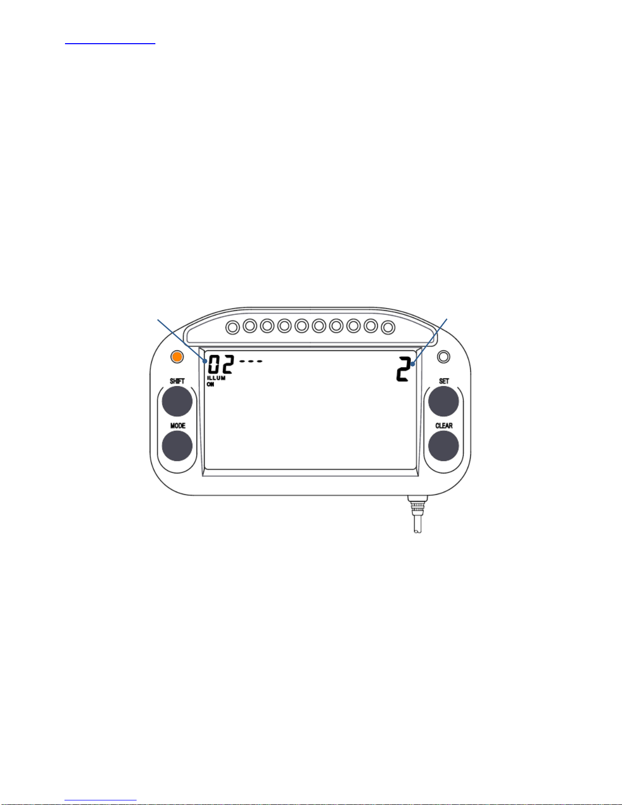
No. 2: Backlight * The backlight is an optional.
Set the backlight brightness.
* Press the CLEAR key and display parameter No. 2.
1. The backlight brightness display flashes at the top right of the screen. Press the
SET key and select backlight OFF (0) or ON (1 – 2). 2 is the brightest setting.
2. Press the CLEAR key to move to the next parameter setting. To exit the setting,
press and hold the CLEAR key for 3 seconds.
* When the user changes from the initial screen to the parameter settings screen,
the backlight turns on at its brightest setting for 7 seconds, regardless of the
backlight ON/OFF setting.
Parameter No.
Backlight brightness
-22-
Page 24
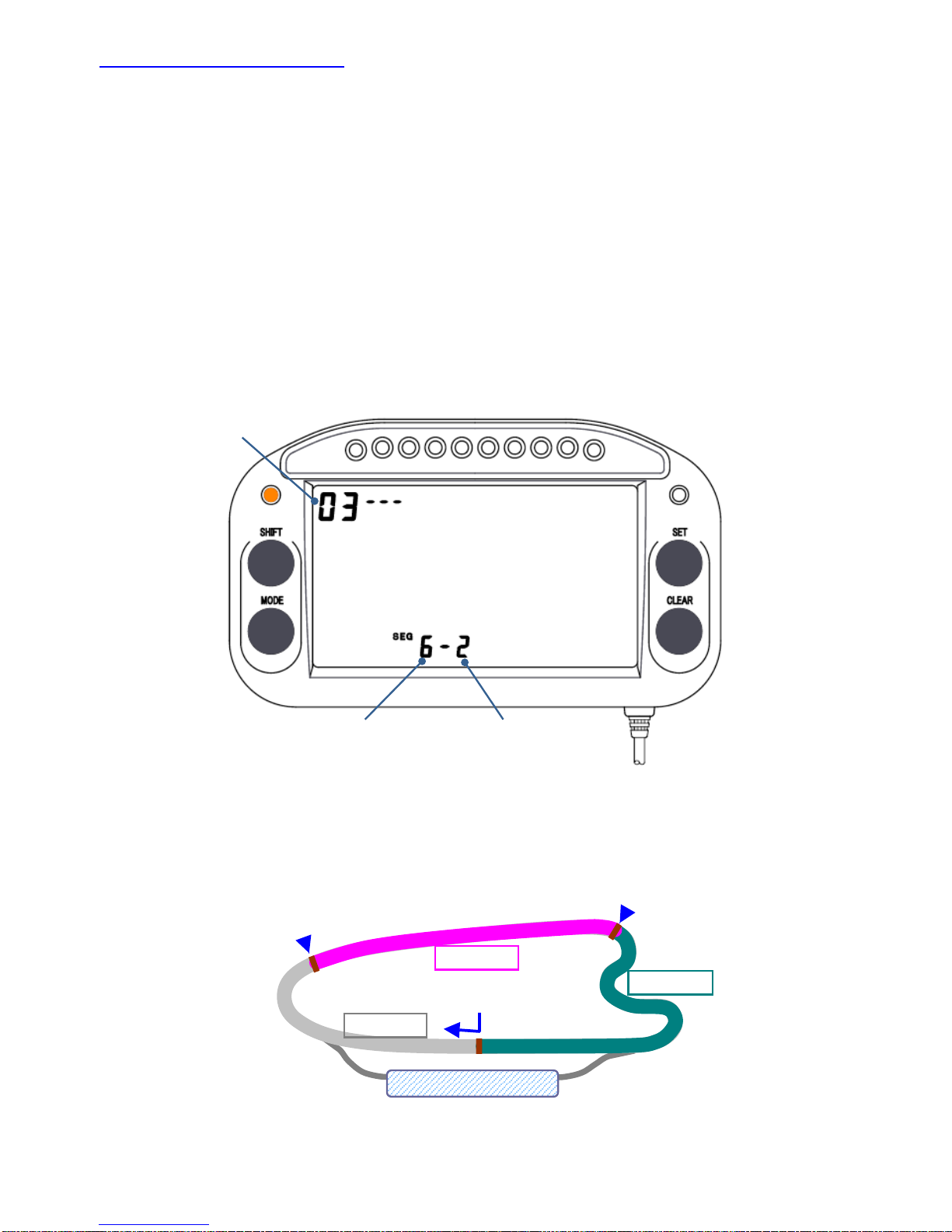
No. 3: Number of Segments
First, set the total number of beacons installed in the course. Next, enter the No. of the
first beacon that will be detected after leaving the pit.
* Press the CLEAR key and display parameter No. 3.
1. The total number of beacons in the course flashes. Press the SET key and enter
the number.
2. Press the SHIFT key to move the flashing part to the right. Then press the set
key and enter the number of the first beacon that will be detected.
3. Press the CLEAR key to move to the next parameter setting. To exit the setting,
press and hold the CLEAR key for 3 seconds.
Parameter No.
Total number of installed
beacons
No. of the beacon first detected
after entering the course
[Setting the No. of the first detected beacon]
If the lap measurement beacon is No. 1, then the course beacon which is first detected
after the vehicle leaves the pit is the No. 2 beacon for measuring the No. 2. section.
Pit
No.1 la
p
beacon
Segment 1
Segment 2
Segment 3
No.2 beacon
No.3 beacon
* If only 1 beacon is installed in the course, set "1 – 1".
-23-
* If section times will not be measured, set "1 – 1".
Page 25
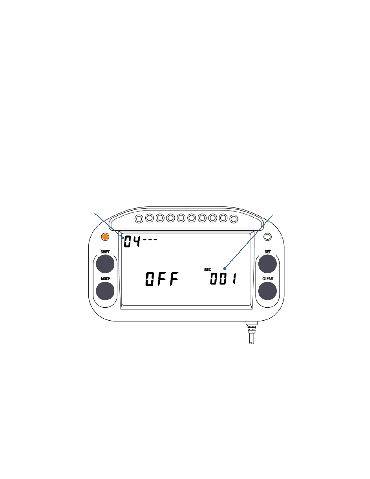
No. 4: Sensor off timer [Default value: 001]
This setting stops the sensor function for the setting period after a beacon is detected.
A sensor off time can be set for example when you will measure only the lap time in
order to disable the sensor function after the lap beacon is detected.
* Press the CLEAR key and display parameter No. 4.
1. To the right of the “SEC” indication, the 3-digit time setting value flashes. The
value changes each time the SET key is pressed. Press the SHIFT key to change
the digit, then use the SET key to enter the value. Values are set in 1 second
increments, with a maximum value of 599 seconds.
2.
Press the CLEAR key to move to the next parameter setting. To exit the setting,
press and hold the CLEAR key for 3 seconds.
* For ordinary driving, use the default setting of 001.
* If the set time is longer than the lap time, lap time measurement will not be possible.
Parameter No.
Set the time in units
of seconds.
-24-
Page 26
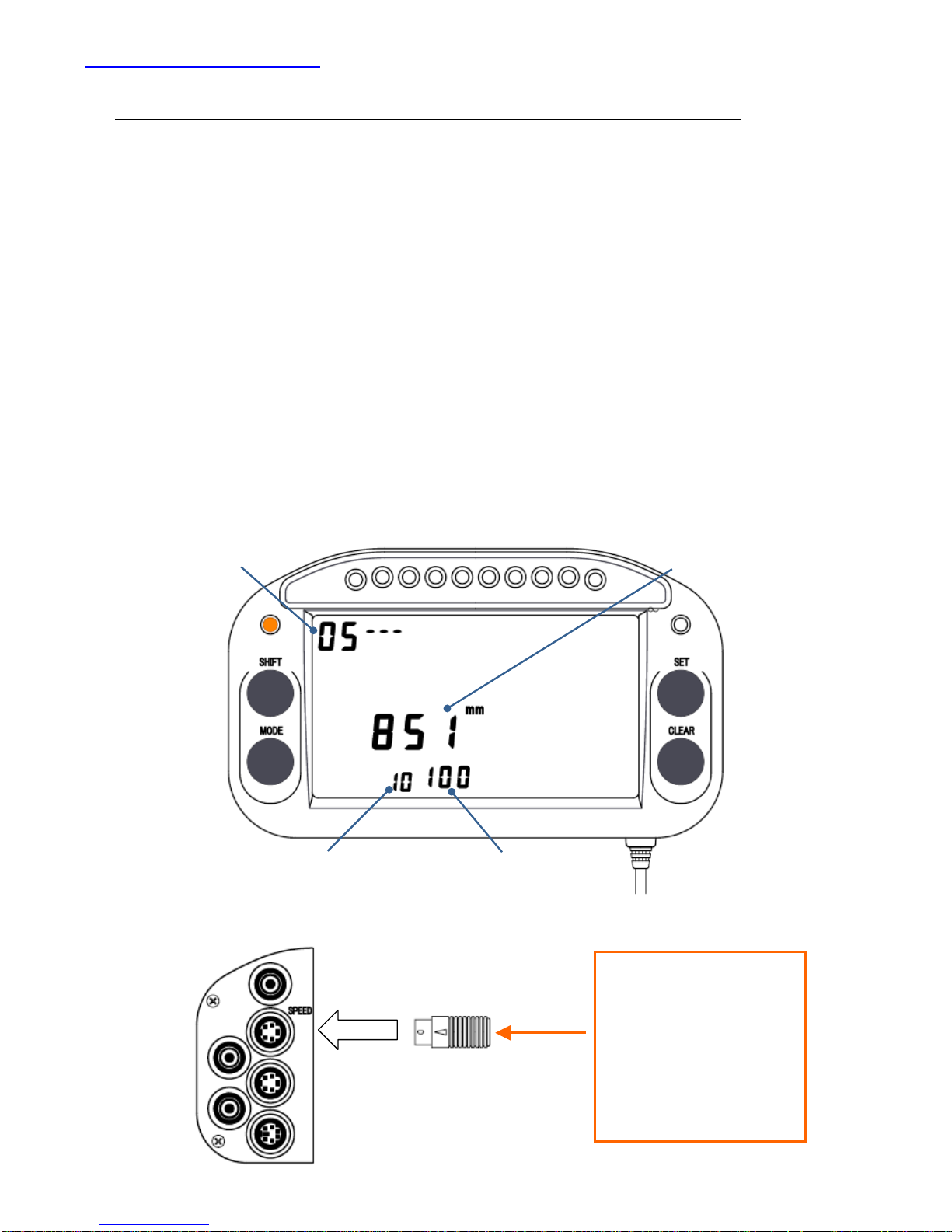
No. 5: Speed Pulse Length
5---: Without speed sensor; engine directly connected to drive shaft
In a vehicle such as a racing kart where the engine is connected directly to the drive
shaft without a clutch, the wheel speed is calculated from the RPM.
* Press the CLEAR key and display parameter No. 5.
1. There is a flashing hyphen or number on the right side of the parameter No.
Press the SET key and enter a hyphen.
2. Press the SHIFT key and move the flashing digit to the circumference of the
drive tires, then press the SET key and enter a number.
3. In the same way, enter the number of sprocket teeth on the drive side and the
number of sprocket teeth on the driven side.
4. Press the CLEAR key to move to the next parameter setting. To exit the setting,
press and hold the CLEAR key for 3 seconds.
Number of sprocke
t
teeth on the driven side
Number of sprocke
t
teeth on the drive side
Circumference of drive tires
Parameter No.
Terminal plug
If the speed is acquired
from the plug cord,
depending on the signal
strength, the signal may
have an effect on the
speed port. If a speed
sensor will not be used, be
sure to install the provided
terminal plug.
-25-
Page 27
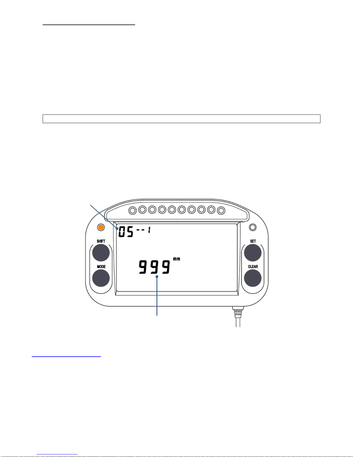
5--1: Using Speed sensor
Set as follows when a speed sensor is used to measure the wheel speed.
1. There is a flashing hyphen or number on the right side of the parameter No.
Press the SET key and enter 1.
2.
Press the SHIFT key and move the flashing digit to the speed pulse length, then
press the SET key and enter a number. Enter the value of the measured tire
circumference divided by the number of sensor detection triggers as the vehicle
speed pulse length.
Speed pulse length = Measured tire circumference ÷ Number of installed magnet triggers
* If the wheel speed signal is acquired from the ECU, refer to the separate provided
materials.
3. Press the CLEAR key to move to the next parameter setting. To exit the setting,
press and hold the CLEAR key for 3 seconds.
Parameter No.
Speed pulse length
No. 6: Units of Speed
Select km/h or m/h (miles) as the units for wheel speed display.
* Press the CLEAR key and display parameter No. 6.
1. The speed units display flashes. Press the SET key and select the units.
-26-
2.Press the CLEAR key to move to the next parameter setting. To exit the setting,
press and hold the CLEAR key for 3 seconds.
Page 28
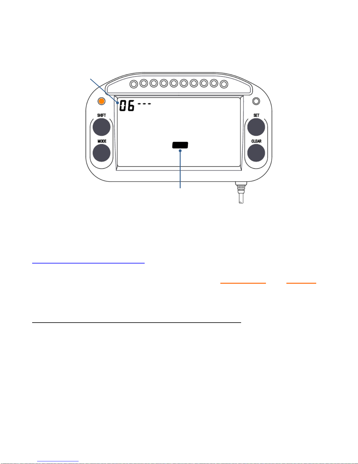
※ If km/h is set, the temperature display is automatically changed to centigrade
display. If m/h is set, the temperature display is automatically set to Fahrenheit
display.
Km/h
Parameter No.
Units of speed
No. 7: Logging start/stop condition
* In order to perform logging, measurement of wheel speed and lap time is
required.
* Press the CLEAR key and display parameter No. 7.
7---: Without Memory card (Measurement and display only)
The memory card is not necessary and logging will not be performed.
1. There is a flashing hyphen or number on the right side of the parameter No.
Press the SET key and enter a hyphen.
2. Press the CLEAR key to move to the next parameter setting. To exit the setting,
press and hold the CLEAR key for 3 seconds.
-27-
Page 29
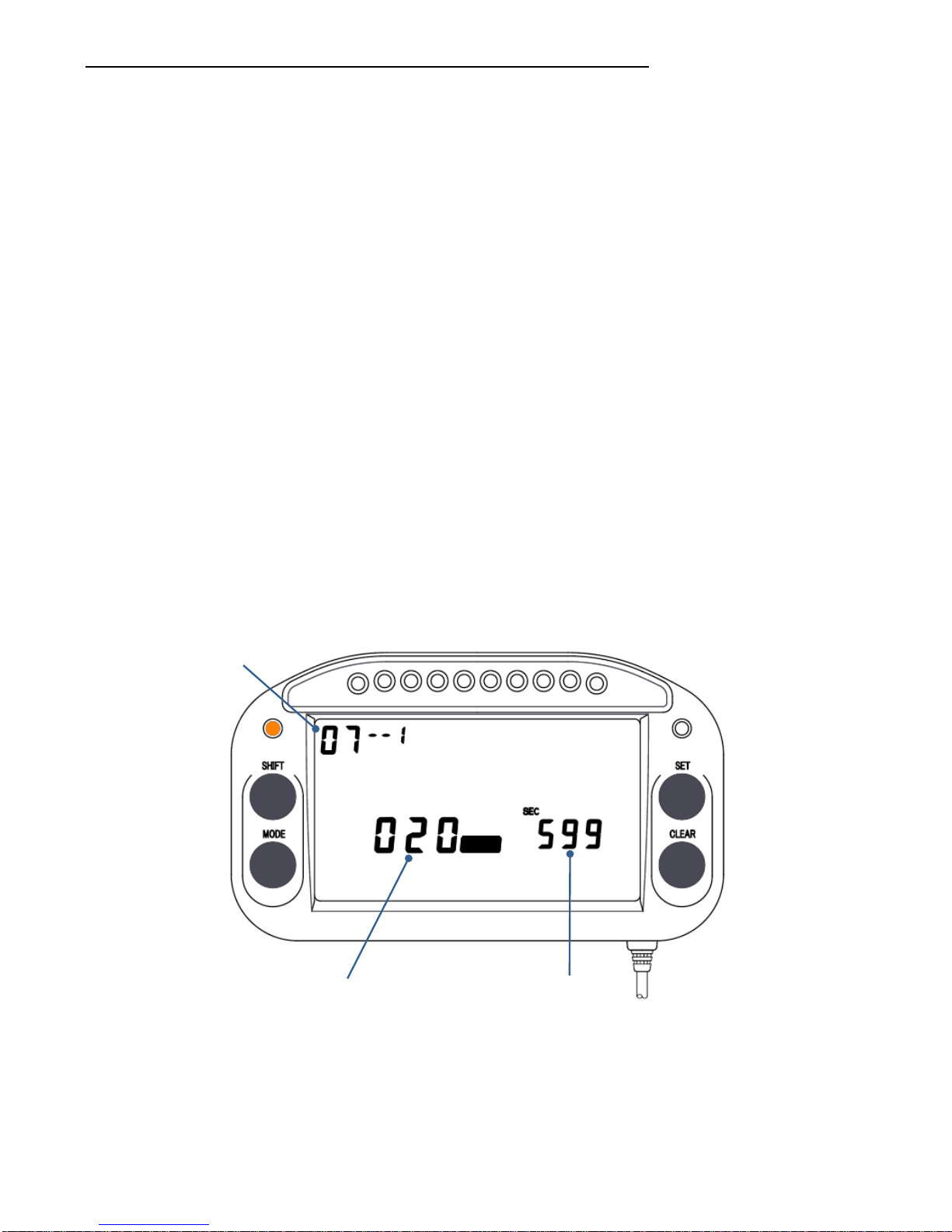
7--1: Perform logging only of laps where lap time is completed. (Default value: 20 km/h,
599 seconds)
The out-lap and in-lap are not measured.
Only the completed laptime data will be logged.
※ A SD memory card is required.
※ Speed measurement is required. Be aware that logging is not possible if the
speed is not measured.
1. There is a flashing hyphen or number on the right side of the parameter No.
Press the SET key and enter 1.
2.
Press the SHIFT key and move the flashing part to the wheel speed display, then
press the SET key and enter a number. When the set speed is reached,
preparation for logging is started. After the vehicle detects the first lap beacon,
logging starts.
3.
Next, press the SHIFT key and move the flashing part to the time display, then
press the SET key and enter a number. Logging is automatically stopped when
the length of time set here has passed after the wheel speed drops below the
speed setting in 2.
4. Press the CLEAR key to move to the next parameter setting. To exit the setting,
press and hold the CLEAR key for 3 seconds.
Time setting
Wheel speed setting
Parameter No.
Km/h
<Example of the above setting>
When the wheel speed exceeds 20 km/h after the vehicle leaves the pit, and the first
lap beacon is detected, the logging is started.
-28-
After repeated laps, when the vehicle enters the pit road, the speed falls below 20 km/h,
and then 599 seconds have passed, logging is automatically stopped.
Page 30
※ Do not turn off the power without stopping the logging. The logging data will be
damaged.
* To stop logging manually, press the CLEAR key.
* To automatically end logging faster when returning to the pit, set a shorter time.
* Be sure to stop logging when entering the pit.
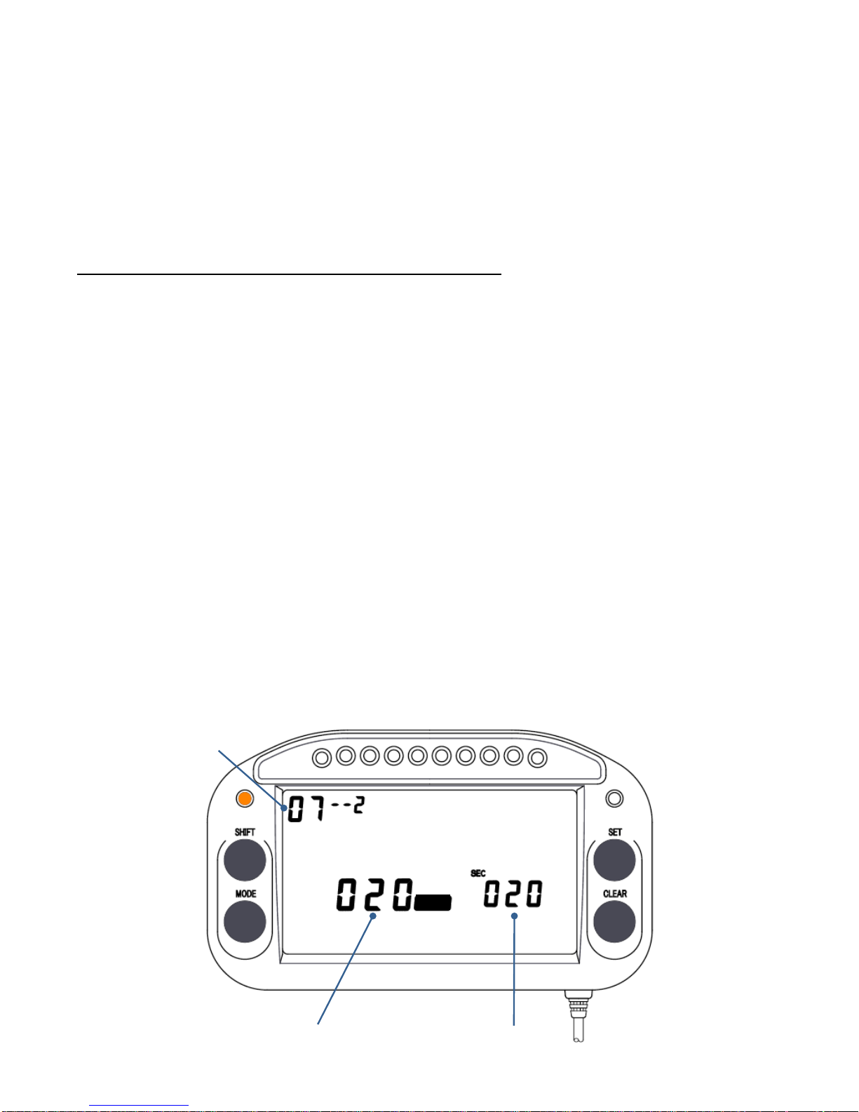
7--2: Logging the lap data from pit exit to pit return.
All lap data is logged from leaving the pit to returning the pit.
※ A SD memory card is required.
※ Speed measurement is required. Be aware that logging is not possible if the
speed is not measured.
1. There is a flashing hyphen or number on the right side of the parameter No.
Press the SET key and enter 2.
2.
Press the SHIFT key and move the flashing part to the wheel speed display, then
press the SET key and enter a number. When the set speed is reached, logging
is started.
3.
Next, press the SHIFT key and move the flashing part to the time display, then
press the SET key and enter a number. Logging is automatically stopped when
the length of time set here has passed after the wheel speed drops below the
speed set in 2.
4. Press the CLEAR key to move to the next parameter setting. To exit the setting,
press and hold the CLEAR key for 3 seconds.
Time setting
Vehicle speed setting
Parameter No.
Km/h
-29-
Page 31

-30-
<Example of the above setting>
When the wheel speed exceeds 20 km/h after the vehicle leaves the pit, logging is
started.
When the measurement laps are finished, the wheel speed drops to below 20 km/h on
the pit road, and then 20 seconds have elapsed, logging is automatically stopped.
* Do not turn off the power without stopping the logging. The logging data will be
damaged.
* To stop logging manually, press the CLEAR key.
* To automatically end logging faster when returning to the pit, set a shorter time.
※ Be sure to stop logging when entering the pit.
※ If the vehicle returns to the course within the set time even after sliding off the
course and slowing to below the set speed, logging is not stopped.
Page 32
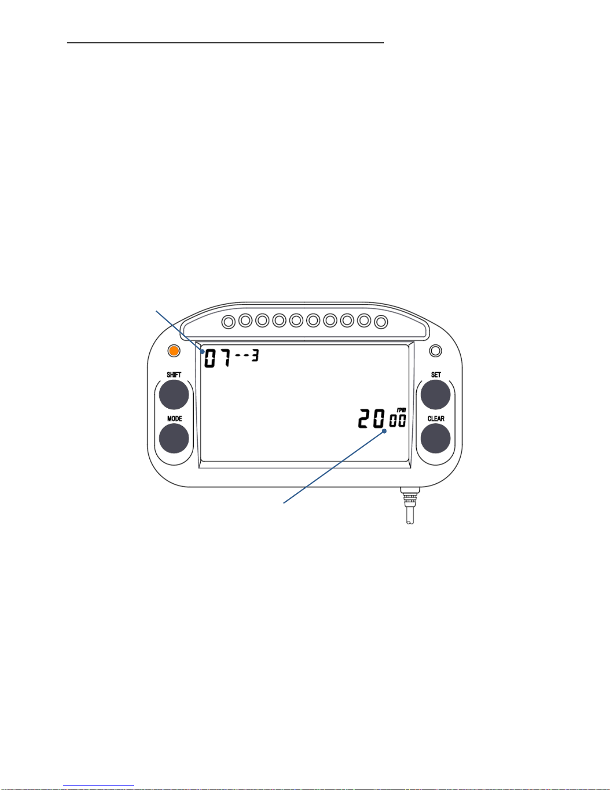
7--3: Logging all data from engine start to engine stop
※ A SD memory card is required.
※ Be aware that logging will not be started if the RPM signal is not acquired.
1. There is a flashing hyphen or number on the right side of the parameter No.
Press the SET key and enter 3.
2.
Press the SHIFT key and move the flashing part to the RPM display, then press
the SET key and enter a number. When the set RPM is reached, logging is
started. When the RPM drops below the set value, logging is automatically
stopped.
3. Press the CLEAR key to move to the next parameter setting. To exit the setting,
press and hold the CLEAR key for 3 seconds.
RPM setting
Parameter No.
* Do not turn off the power without stopping the logging. The logging data will be
damaged.
* To stop logging manually, press the CLEAR key.
* To automatically stop logging sooner when returning to the pit, set a higher
RPM.
* Be sure to stop logging when entering the pit.
-31-
Page 33
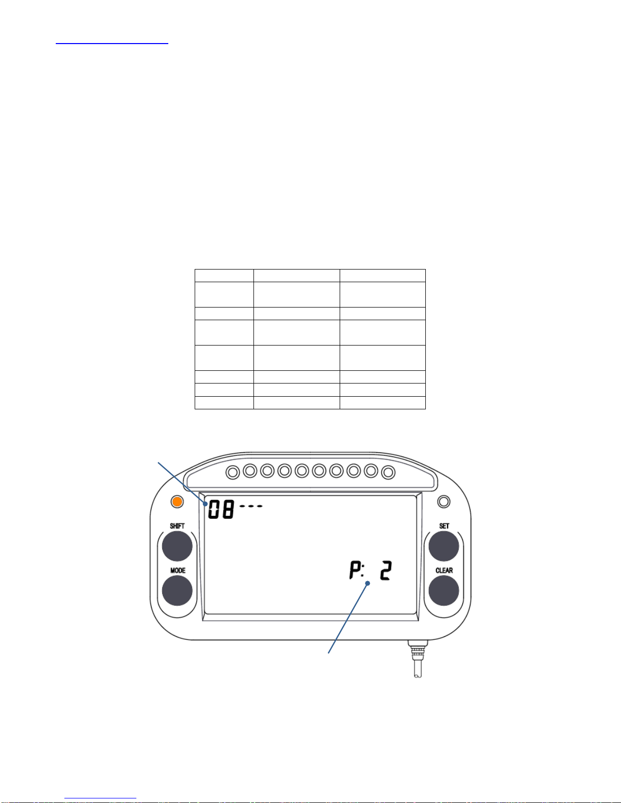
No. 8: REV position
Set the engine type.
* Press the CLEAR key and display parameter No. 8.
1. The tachometer position display flashes. Press the SET key and select the
tachometer position. Refer to the list below.
2. Press the CLEAR key to move to the next parameter setting. To exit the setting,
press and hold the CLEAR key for 3 seconds.
※
In rare cases, the parameter listed below may not be suitable. In that case,
change the value to the suitable configuration for your engine.
P: 1 4-stroke 1-cylinder
P: 2 2-stroke
4-stroke
1-cylinder
2-cylinder
P: 3 4-stroke 3-cylinder
P: 4 2-stroke
4-stroke
2-cylinder
4-cylinder
P: 6 2-stroke
4-stroke
3-cylinder
6-cylinder
P: 8 4-stroke 8-cylinder
P: 10 4-stroke 10-cylinder
P: 12 4-stroke 12-cylinder
Parameter No.
Tachometer position
-32-
Page 34
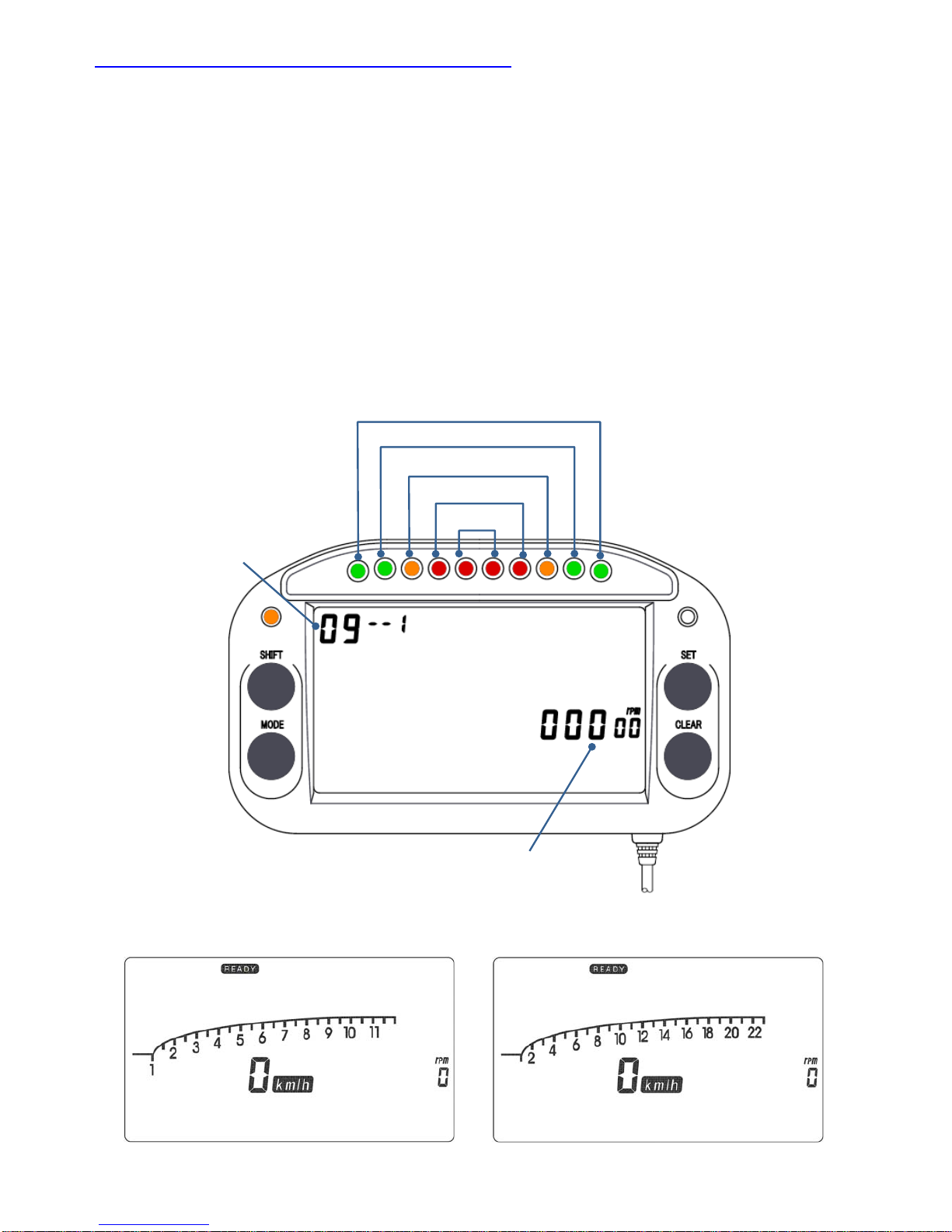
No. 9: Information lamp and bar-graph full scale
The RPM warning lamp setting can be set for each LED from 9--1 to 5. When the
RPM exceeds the set value, the corresponding LED illuminates.
* Press the CLEAR key and display parameter No. 9.
1. There is a flashing hyphen or number on the right side of the parameter No.
Press the SET key and enter the LED number to set. For the numbers, refer to
the figure below.
2.
Press the SHIFT key and move the flashing part to the RPM display. Press the
SET key and enter values.
3. Press the CLEAR key to move to the next parameter setting. To exit the setting,
press and hold the CLEAR key for 3 seconds.
-33-
* If the engine speed for 9--5 (LED: red) is set higher than 12,000 rpm, the bar graph scale is automatically
changed from 12,000 rpm display to 23,000 rpm display.
Parameter No.
RPM
9--5 Red
9--4 Red
9--3 Orange
9--2 Green
9--1 Green
12,000 rpm scale 23,000rpm scale
Page 35
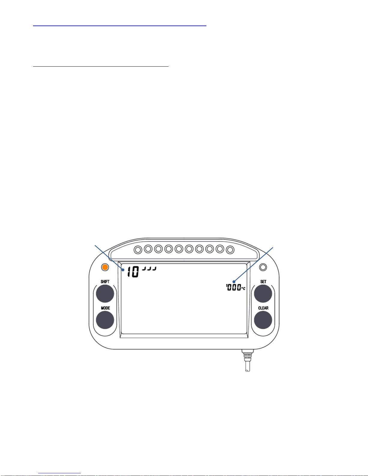
No. 10 (TEMP1) & 11 (TEMP2): Temperature Alarm
* Press the CLEAR key and display parameter No. 10/11.
10┘┘┘ TEMP1 upper limit alarm setting (Default value: 000; alarm disabled)
When the temperature exceeds the set value, ℃ flashes and the orange LED on the
right side illuminates.
1. The ┘┘┘ (upper limit mark) or ┐┐┐(lower limit mark) on the right side of the
parameter No. flashes. Press the SET key and select ┘┘┘(upper limit mark).
2. Press the SHIFT key and move the flashing part to the temperature display, then
press the SET key and enter a number.
3. To set the TEMP 1 lower limit alarm, press the SHIFT key and move the flashing
part to the right side of the parameter No.
4.
Press the CLEAR key to move to the next parameter setting. To exit the setting,
press and hold the CLEAR key for 3 seconds.
Parameter No. Temperature
-34-
Page 36
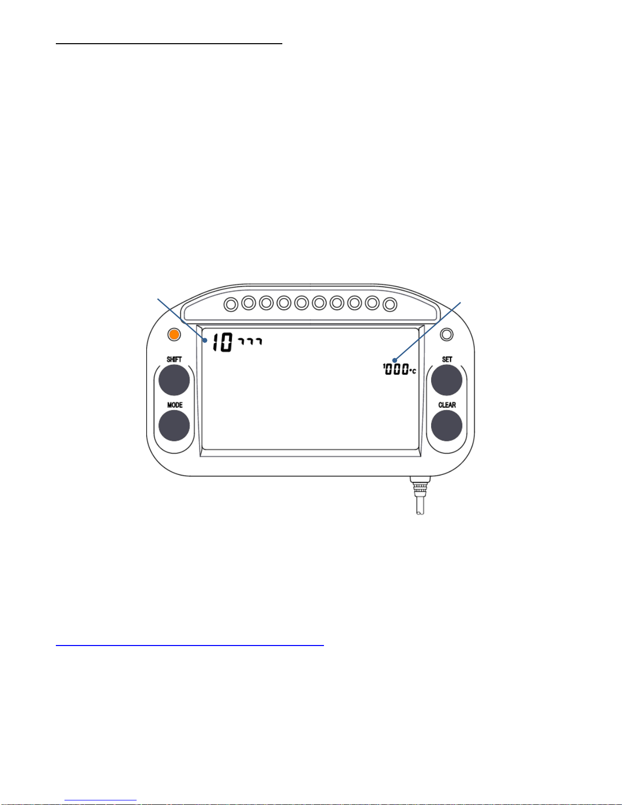
10┐┐┐ TEMP1 lower limit alarm setting (Default value: 000; alarm disabled)
When the temperature drops below the set value, ℃ flashes and the orange LED on
the left side illuminates.
1. The ┘┘┘ (upper limit mark) or ┐┐┐(lower limit mark) on the right side of the
parameter No. flashes. Press the SET key and select ┐┐┐(lower limit mark).
2. Press the SHIFT key and move the flashing part to the temperature display, then
press the SET key and enter a number.
3. Press the CLEAR key to move to the next parameter setting. To exit the setting,
press and hold the CLEAR key for 3 seconds.
Parameter No.
Temperature
In the same way, set the No. 11 (TEMP2) temperature upper limit and lower limit alarms.
No. 12 (Press1) & 13 (Press2): Pressure Alarm
* These settings are used for pressure measurement. This function cannot be used
with S All & S Lite.
-35-
Page 37
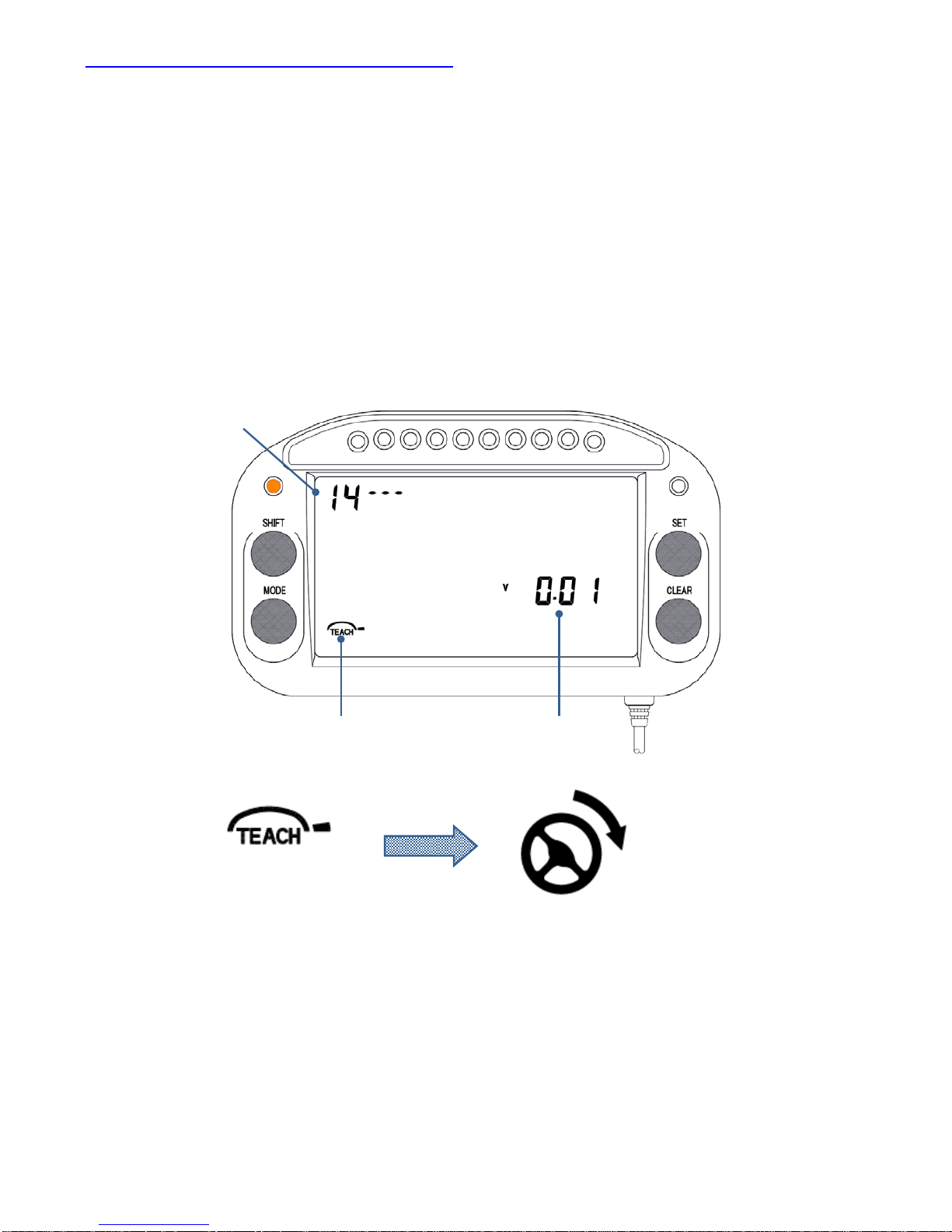
No. 14: Calibration for Steering movement
These settings are used for measuring the steering angle.
* Press the CLEAR key and display parameter No. 14.
1. Install the steering angle sensor onto the vehicle and connect the sensor to the
LAPCOM unit. Verify that the “TEACH” indicator is flashing. The indicator mark is
on the right side. If “TEACH” is not flashing, the LAPCOM unit does not
recognize the sensor. Check the connection and turn the power off/on.
2. First, press and hold the SET key for 2 seconds when the steering wheel is
turned to the right.
Parameter No.
Sensor output
lower limit
Indicator
Press and hold the SE
T
key for 2 seconds when
the steering wheel is
turned to the right.
The indicator mark is
on the right side.
3. If calibration was completed correctly, the sensor output lower limit value is
determined automatically and the indicator mark moves to the left side.
4. Press and hold the SET key for 2 seconds when the steering wheel is turned to
the left.
5. If calibration was completed correctly, the sensor output upper limit value is
automatically determined, and the screen automatically changes to the next
setting screen (parameter No. 15).
-36-
Page 38
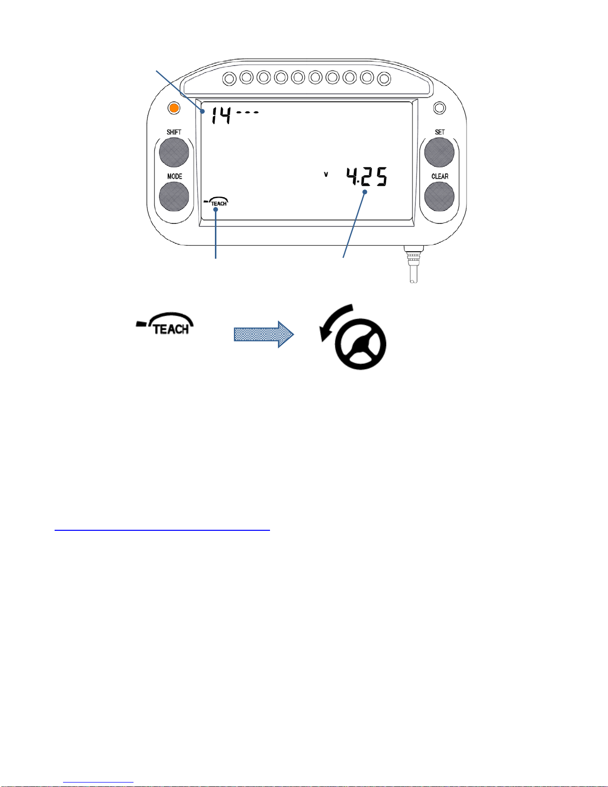
Parameter No.
Sensor output upper limit:
Less than 5V
Indicator
Press and hold the SE
T
key for 2 seconds when
the steering wheel is
turned to the left.
The indicator mark
moves to the left side.
※ Use within a sensor output range of 0.01 – 4.99.
※ In general, do not use a displacement sensor that exceeds 5 kΩ.
No. 15: Calibration for Throttle position
These settings are used for measuring the throttle position.
* Press the CLEAR key and display parameter No. 15.
1. Install the throttle position sensor onto the vehicle and connect the sensor to the
LAPCOM unit. Verify that the “TEACH” indicator is flashing. The indicator mark is
at the bottom. If “TEACH” is not flashing, the LAPCOM unit does not recognize
the sensor. Check the connection and turn the power off/on.
2. Press and hold the SET key for 2 seconds when the throttle is closed.
-37-
Page 39
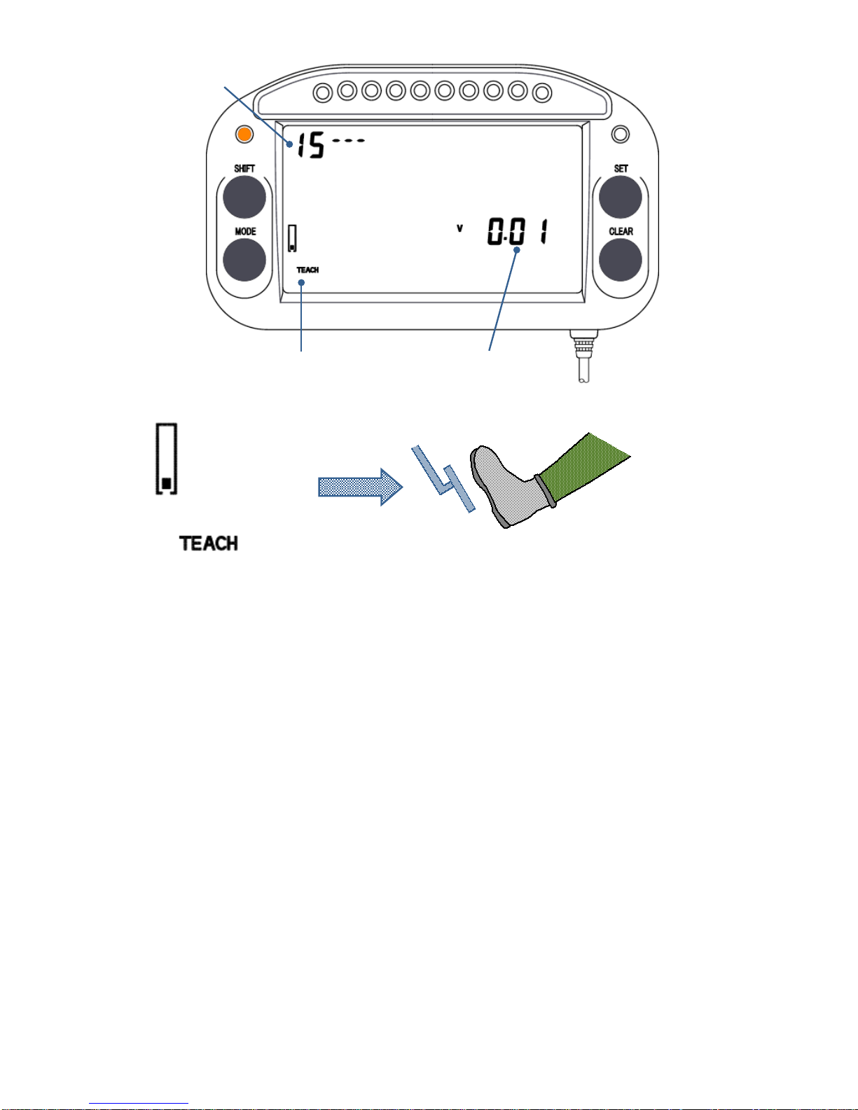
Parameter No.
Sensor output
lower limit
Indicator
The indicato
r
mark is at the
bottom.
Press and hold the SE
T
key for 2 seconds when
the throttle is closed.
3. If calibration was completed correctly, the sensor output lower limit value is
determined automatically and the indicator mark moves to the top side.
4. Press and hold the SET key for 2 seconds when the throttle is fully opened.
5. If calibration was completed correctly, the sensor output upper limit value is
automatically determined, and the screen automatically changes to the next
setting screen (parameter No. 16).
-38-
Page 40
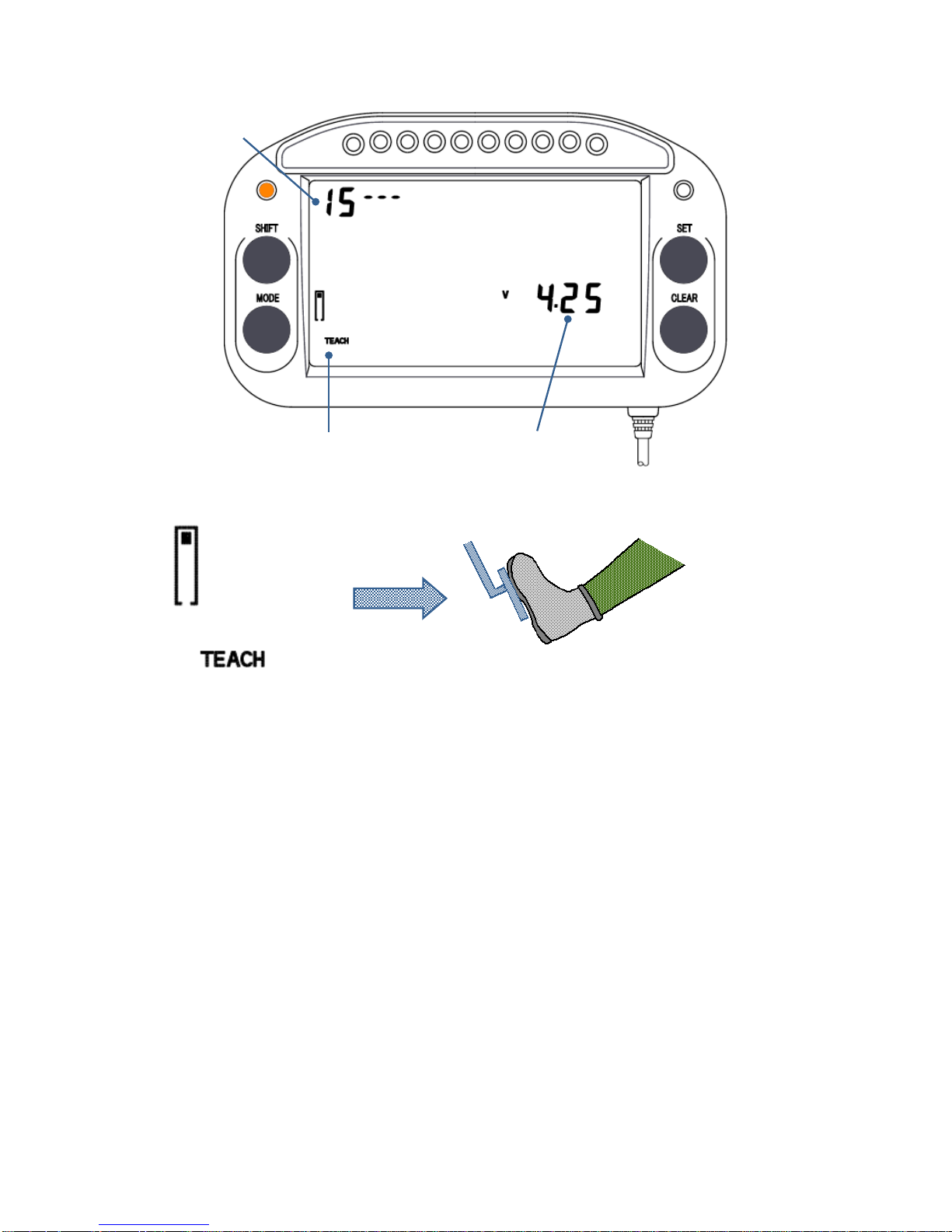
Sensor output upper limit:
Less than 5V
Indicator
Parameter No.
The indicato
r
mark is on the
top side.
Press and hold the SET
key for 2 seconds when
the throttle is fully opened.
※
Use within a sensor output range of 0.01 – 4.99.
※ A displacement sensor that exceeds 5 kΩ cannot be used.
-39-
Page 41

-40-
No. 16: Gear position
* Press the CLEAR key and display parameter No. 16.
16---: No gear display
1. There is a flashing hyphen or number on the right side of the parameter No.
Press the SET key and enter a hyphen.
2. Press the CLEAR key to move to the next parameter setting. To exit the setting,
press and hold the CLEAR key for 3 seconds.
16--1: Calculate the gear ratios.
If no information is available concerning the gear ratio for the vehicle, this calculates
the final reduction gear ratio for each gear No. during actual vehicle driving.
※ Take the speed signal from a drive-side wheel so that the display will be correct.
1. There is a flashing hyphen or number on the right side of parameter No. 16.
Press the SET key and enter 1.
2.
Press the SHIFT key and move the flashing part to the total number of gears
display. Press the SET key and enter the total number of gears.
3.
Press the SHIFT key and move the flashing part to the tolerance display. Press
the SET key and enter value. * Begin from 3%.
4.
Press the SHIFT key and move the flashing part to the pulse number display.
Press the SET key and enter the pulse count.
5.
Press the SHIFT key and move the flashing part to the gear No. display. Actually
drive the vehicle. Press the SET key and enter "1" for the 1st gear No., then
press and hold the SET key until the TEACH indicator turns on. The unit begins
calculating. After some time, when the TEACH indicator turns off and a value
appears in the gear ratio display, teaching is completed.
Page 42
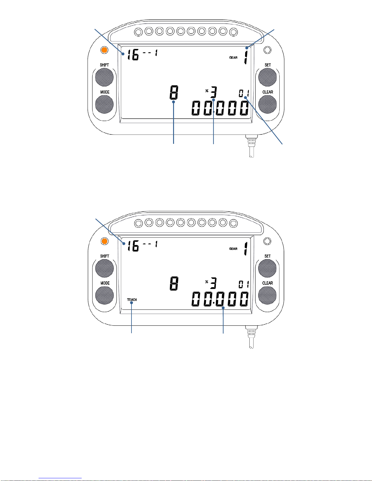
Tolerance
Total numbe
r
of gears
Gear No.
Pulse number
Parameter No.
6. Repeat the procedure beginning from Step 4, and calculate and set the final gear
ratio for each gear in the same way.
TEACH indicator Gear ratio
Parameter No.
7. Press the CLEAR key to move to the next parameter setting. To exit the setting,
press and hold the CLEAR key for 3 seconds.
* If the gear ratios between gears are close to each other, variation in the gear
display may occur. This may be corrected by reducing the allowable error value.
-41-
Page 43
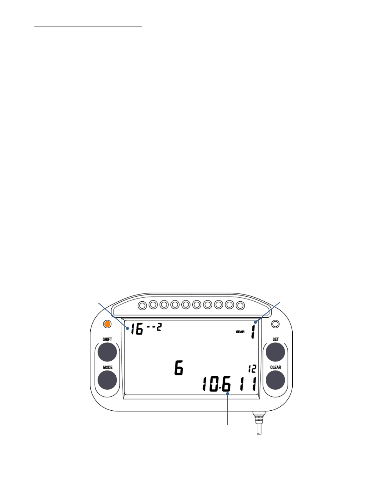
16--2: Enter the gear ratios.
If accurate information is available concerning the primary reduction gear ratio,
secondary reduction gear ratio, and gear ratio for each gear of the vehicle, directly
enter the gear ratio for each gear No.
※ If the vehicle speed is acquired from any wheel other than a drive wheel, the
correct gears will not be displayed.
※ The total number of gears and pulse count are set in 16--1.
※ The settings for 16--1 and 16--2 are linked and the parameter information is
shared between them. If the gear ratio is changed in either setting, the change is
applied to both.
1. There is a flashing hyphen or number on the right side of the parameter No.
Press the SET key and enter 2.
2.
Press the SHIFT key and move the flashing part to the gear ratio display.
Calculate the 1st gear final reduction ratio from the primary reduction gear ratio,
secondary reduction gear ratio, and gear ratio of each gear for the vehicle. Press
the SET key and enter the number.
3.
Press the SHIFT key and move the flashing part to the gear No. display. For 1st
gear, press the SET key and enter "1" for the gear No.
Gear ratio
Gear No.
Parameter No.
-42-
Page 44
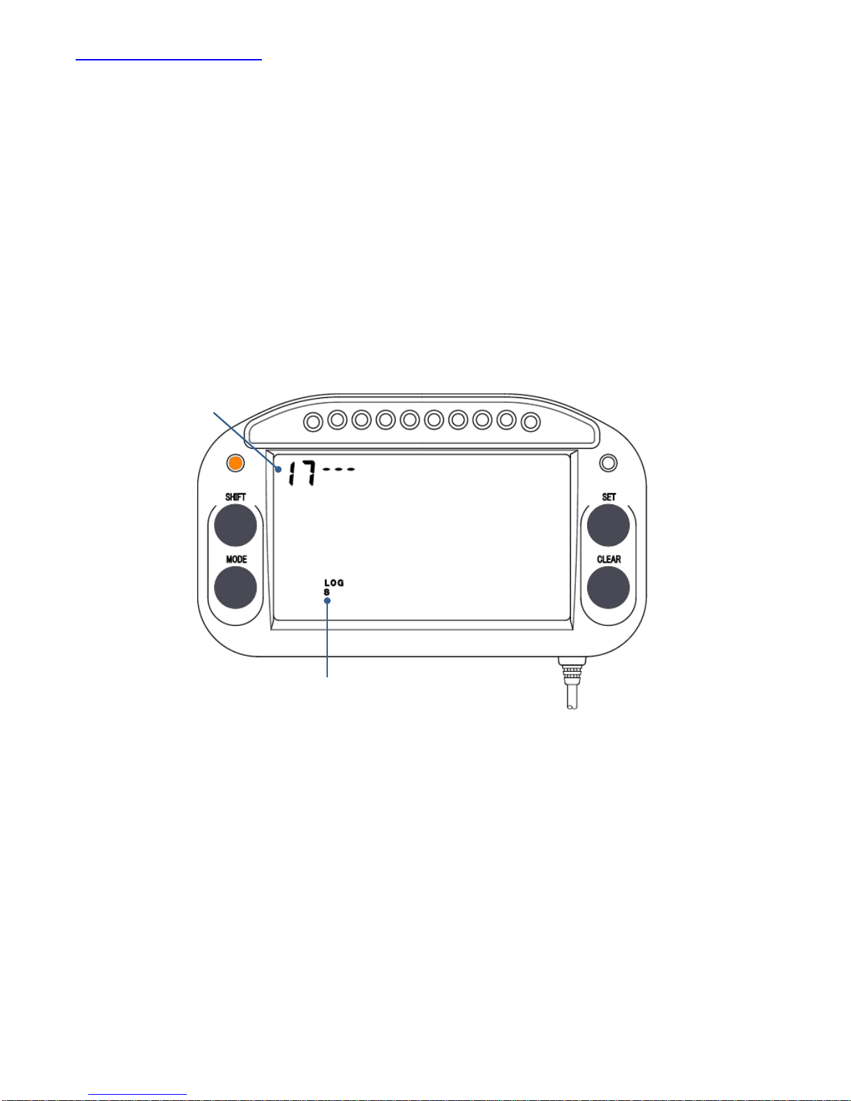
No. 17: Logging interval
The logging interval can be selected.
* Press the CLEAR key and display parameter No. 17.
1. The logging interval display flashes. Press the SET key and select one of the
following: S (0.1 second interval), M (0.2 second interval), L (0.5 second interval),
or off (0.05 second interval).
※ Ordinarily, only the S setting should be used.
※ Off (0.05 second interval) is available only on the S ALL 100 PLUS, S LITE 100
PLUS, and S SEPA 100 PLUS models.
2. Press the CLEAR key to move to the next parameter setting. To exit the setting,
press and hold the CLEAR key for 3 seconds.
Parameter No.
Logging interval
-43-
Page 45
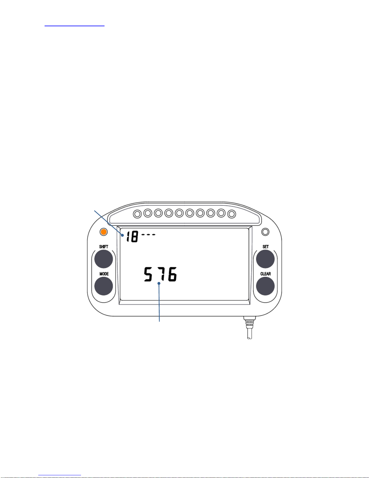
No. 18: Baud rate
When telemetry is operated using radio waves, a cellular phone, the internet, or other,
set the communications speed here.
* Press the CLEAR key and display parameter No. 18.
1. The baud rate display flashes. Press the SET key and select the correct
communications speed setting (96 (9600 bps) – 576 (57600 bps)) for the
communications device used.
2. Press the CLEAR key to move to the next parameter setting. To exit the setting,
press and hold the CLEAR key for 3 seconds.
Parameter No.
Baud rate
-44-
Page 46
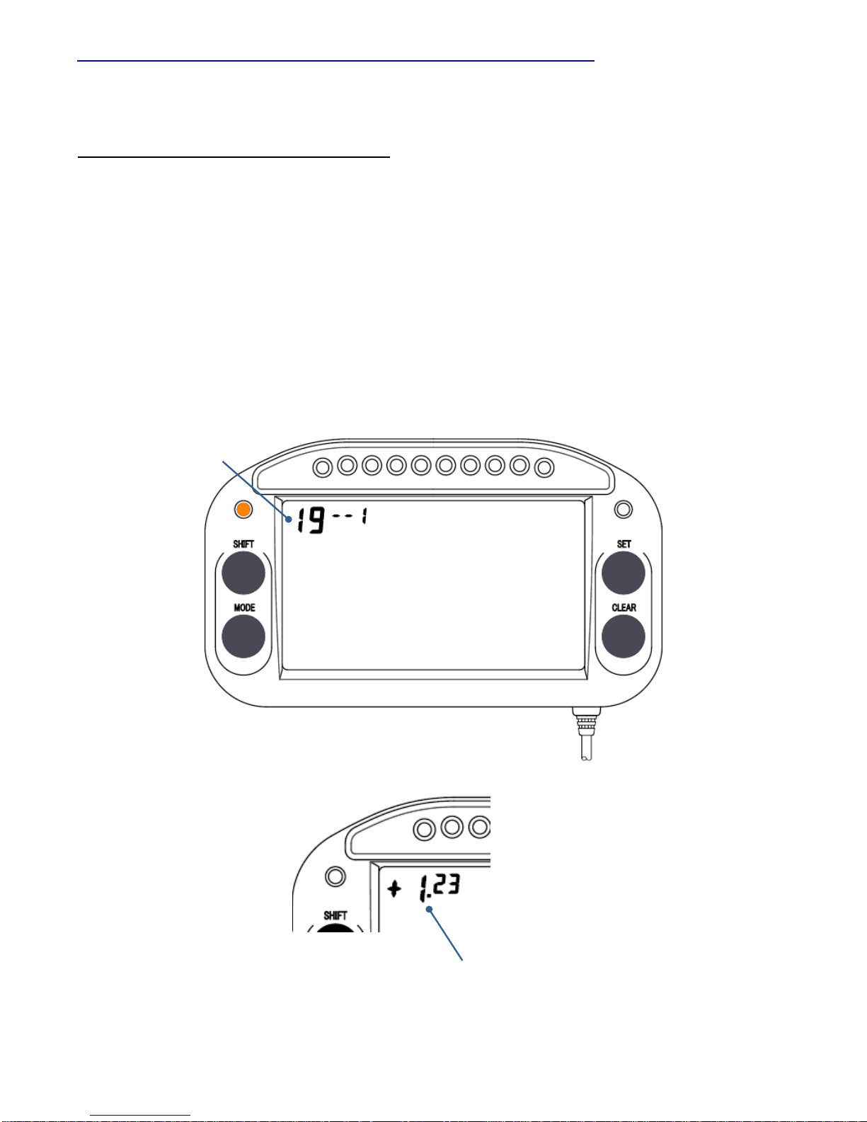
No. 19: Time difference with previous lap, best lap, and target lap
* Press the CLEAR key and display parameter No. 19.
19--1: Comparison with previous lap
Set to compare the last lap with the lap before the last lap.
1. There is a flashing hyphen or number on the right side of the parameter No.
Press the SET key and enter 1.
2. Press the CLEAR key to move to the next parameter setting. To exit the setting,
press and hold the CLEAR key for 3 seconds.
Parameter No.
T
ime difference
-45-
Page 47
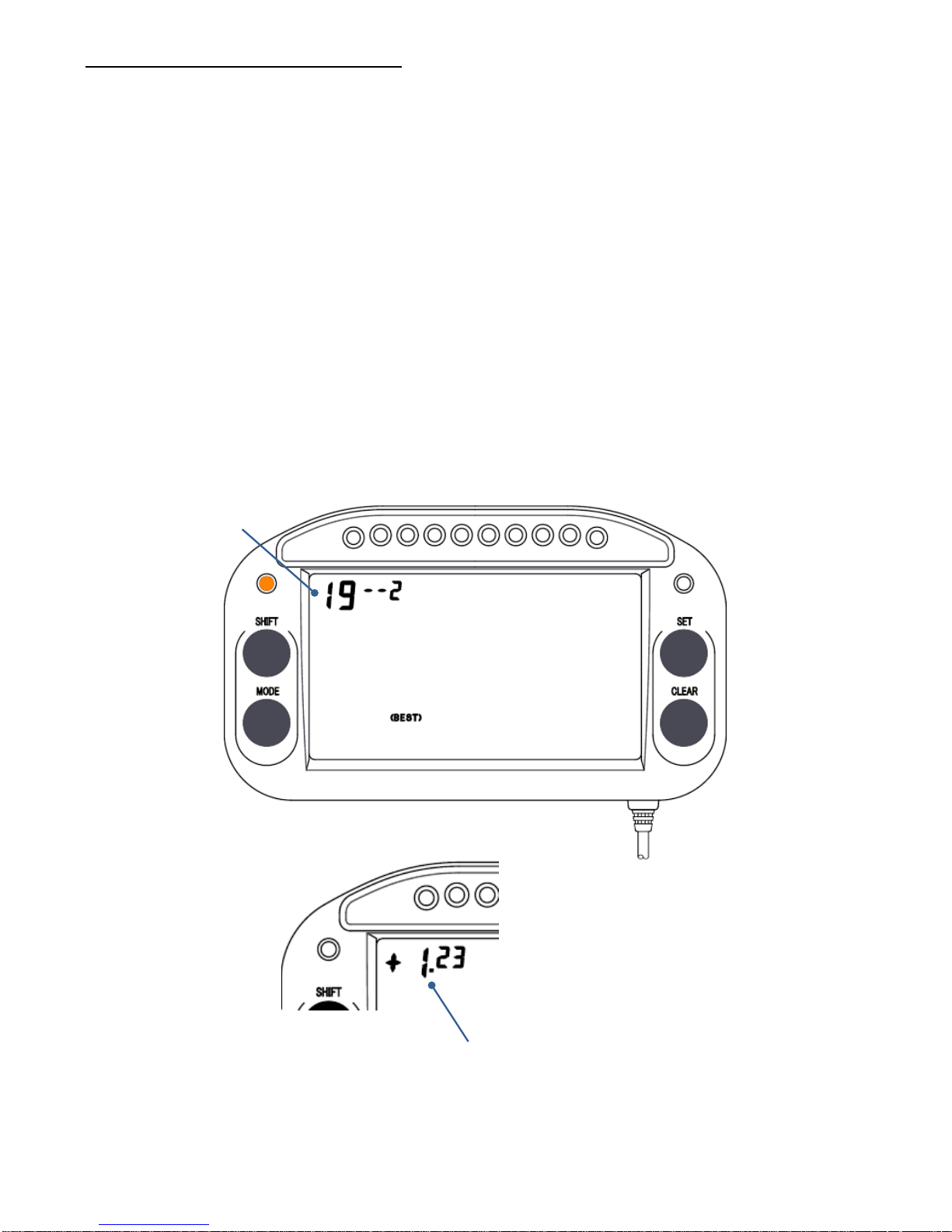
19--2: Comparison with best time
Set to compare the last lap with the best lap.
1. Display the best lap time after the course is driven. A comparison with the
displayed best lap time will be shown.
※ Even if the best time is updated during driving, the best time used as the
standard for comparison is not updated.
2. Display parameter No. 19 on the parameter setting screen. There is a flashing
hyphen or number on the right side of the parameter No. Press the SET key and
enter 2. The “BEST” indication turns on.
3. Press the CLEAR key to move to the next parameter setting. To exit the setting,
press and hold the CLEAR key for 3 seconds.
Parameter No.
Time difference
※ To prevent an invalid time being displayed as the best time, delete the invalid
time information and display the correct best time.
-46-
Page 48
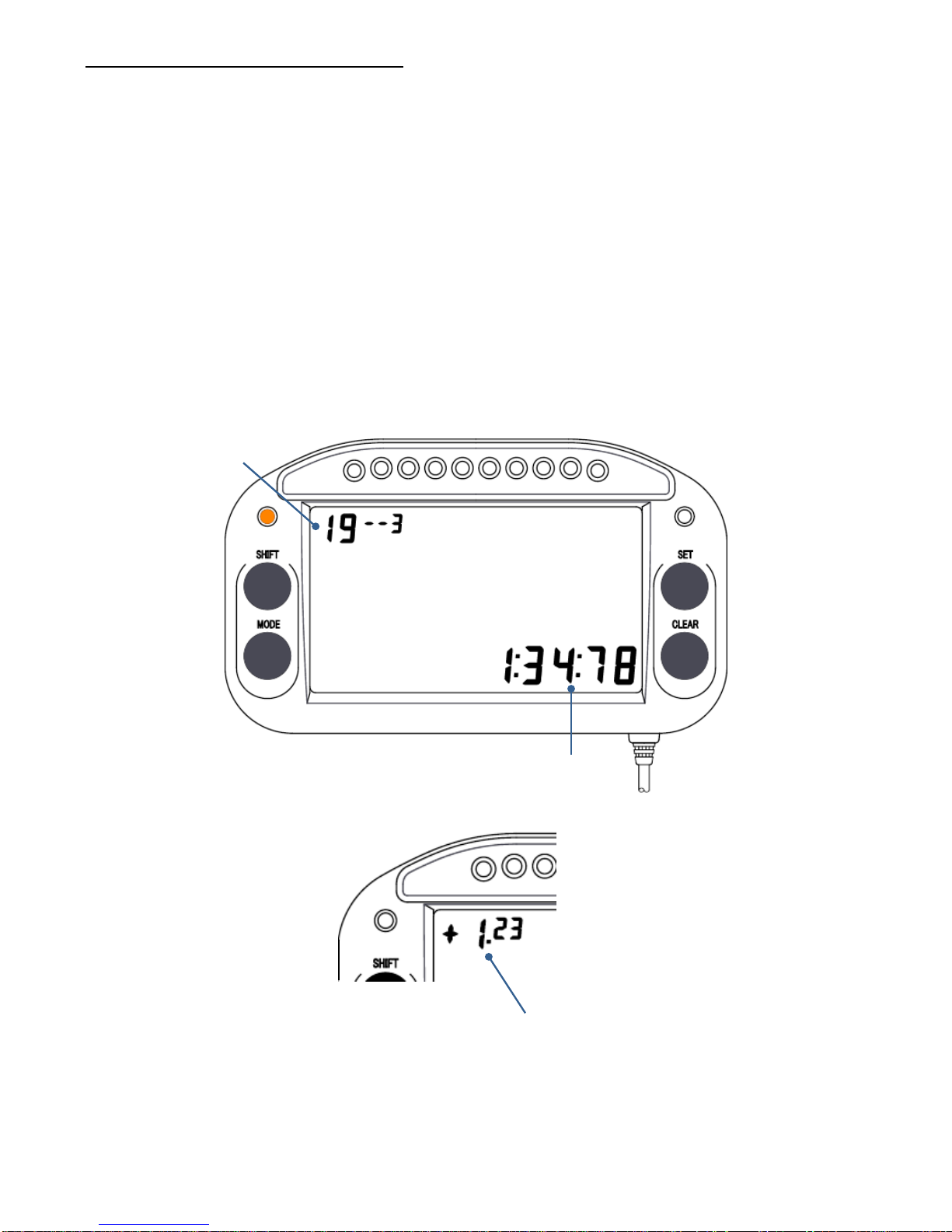
19--3: Comparison with target lap
Set to compare the last lap with the setting target lap time.
1. There is a flashing hyphen or number on the right side of the parameter No.
Press the SET key and enter 3.
2.
Press the SHIFT key and move the flashing part to the target lap time setting.
Press the SET key and enter a number.
3. Press the CLEAR key to move to the next parameter setting. To exit the setting,
press and hold the CLEAR key for 3 seconds.
Target lap time
Parameter No.
Time difference
-47-
Page 49
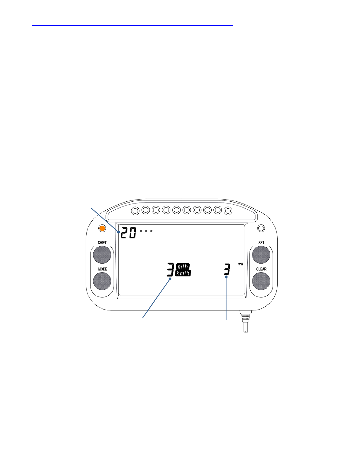
No. 20: Averaging number of speed and RPM data sampling
The sampling average number for wheel speed and RPM can be set. A smaller
average number yields better responsiveness.
* Press the CLEAR key and display parameter No. 20.
1. The wheel speed sampling average number display flashes. Press the SET key
and enter a number.
2.
Press the SHIFT key and move the flashing part to the RMP sampling average
number display. Press the SET key and enter a number.
3. Press the CLEAR key to move to the next parameter setting. To exit the setting,
press and hold the CLEAR key for 3 seconds.
Averaging number
of RPM sampling
Averaging number of
wheel speed sampling
Parameter No.
-48-
Page 50
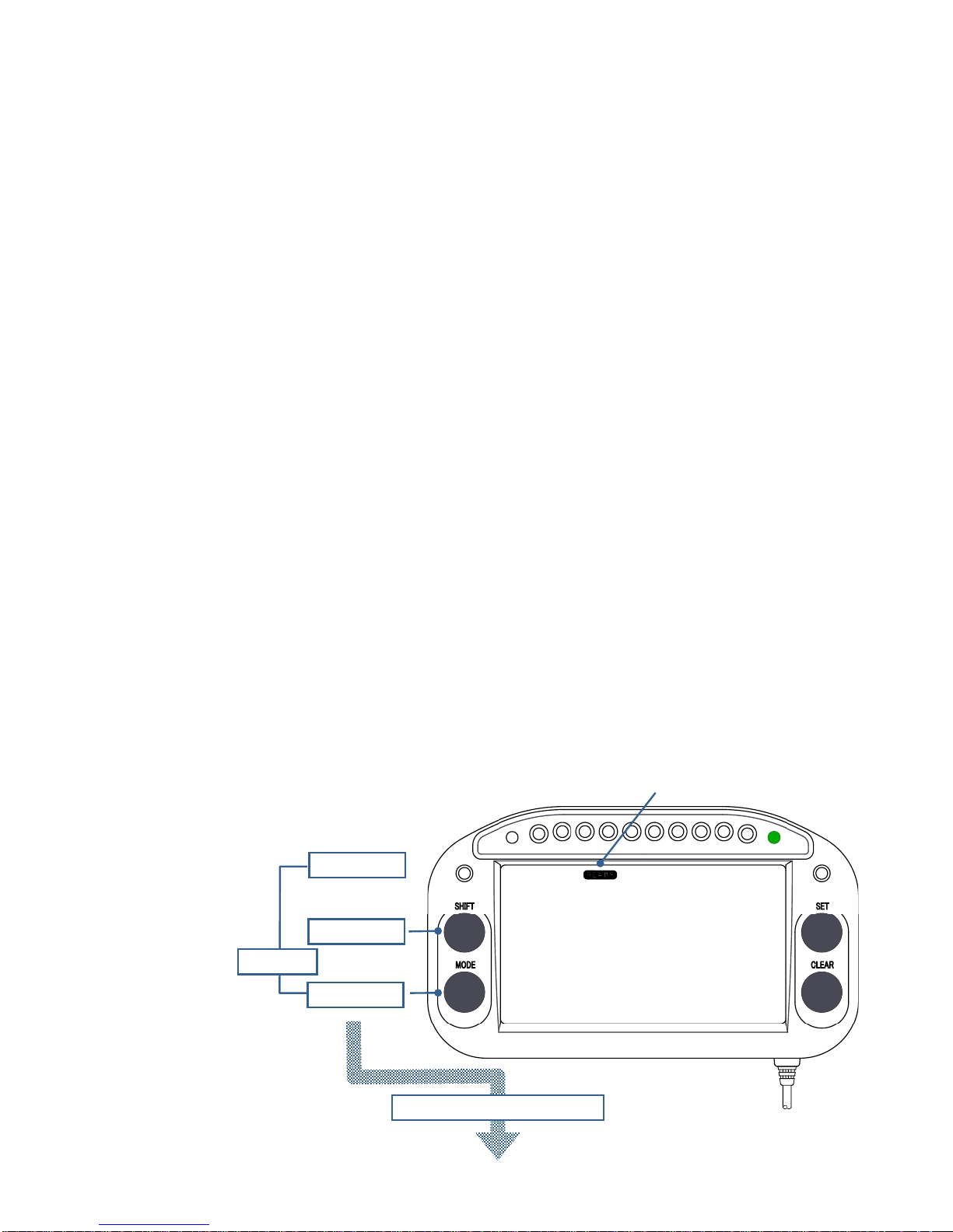
8) Saving and Transferring Parameter Settings
The main unit parameter settings can be saved to a memory card, and the parameter
settings on a memory card can be transferred to the main unit.
※ The file name on the memory card is "PARA" and the extension is ".bin".
※ If the file name and extension are changed to anything other than "PARA.bin",
the logger will be unable to recognize the file.
※ Do not format the memory card. A formatted memory card cannot be used.
※ If the setting was ended with “PP--2” by pressing the CLEAR key for 3 seconds,
it is possible to operate the unit using the parameters saved on the memory card.
However, ordinarily, end with “PP--1”, and operate using the parameters in the
main unit memory “PP--1".
-49-
<Saving the parameters in the main unit to the memory card>
1. Verify that [READY] is displayed on the display screen. If [READY] is not
displayed, press the CLEAR key to display it.
2. Insert the memory card into the main unit.
3. Press and hold switch 1, the SHIFT key, and the MODE key at the same time for
3 seconds. The screen changes to the parameter selection screen, and either
PP--1 or PP--2 is displayed.
4. Press the SET key and display PP--1.
5. Press and hold the SHIFT key for 3 seconds. The display turns off for an instant,
and the parameters in the main unit memory are saved onto the memory card.
6.
Verify that PP--1 is displayed, then press and hold the CLEAR key for 3 seconds.
The screen returns to the initial screen, and [READY] is displayed.
READY
To parameter position screen
+
SHIFTキー
MODE
キ
ー
+
Switch 1
MODE key
SHIFT key
3 seconds
Page 51
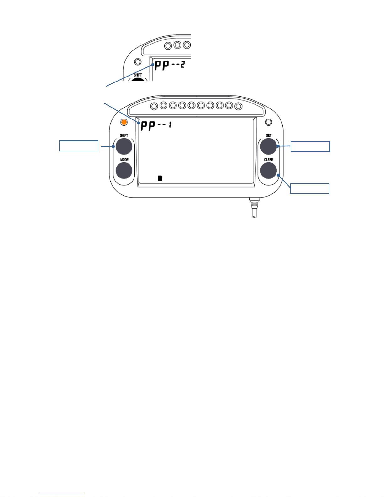
Display PP--1 and
finish the setting by
pressing and holding
for 3 seconds then
go back to [READY]
display.
CLEAR key
SETキー
SHIFTキー
The display of PP--1
and PP--2 changes
each time the key is
pressed.
SET key
SHIFTキー
Press and hold for 3
seconds, then a
parameter will be
transferred from the
main unit to a
memory card, o
r
from a memory card
to the main unit.
SHIFT key
PP--1 or PP--2
will display
<Transferring the parameters on a memory card to the main unit>
1. Verify that [READY] is displayed on the display screen. If [READY] is not
displayed, press the CLEAR key to display it.
2. Insert the memory card into the main unit.
3. Press and hold switch 1, the SHIFT key, and the MODE key at the same time for
3 seconds. The screen changes to the parameter selection screen, and either
PP--1 or PP--2 is displayed.
4. Press the SET key and display PP--2.
5. Press and hold the SHIFT key for 3 seconds. The display turns off for an instant,
and the parameters on the memory card are transferred to the main unit memory.
6. Press the SET key and display PP--1.
7. Verify that PP--1 is displayed, then press and hold the CLEAR key for 3 seconds.
The screen returns to the initial screen, and [READY] is displayed.
-50-
Page 52
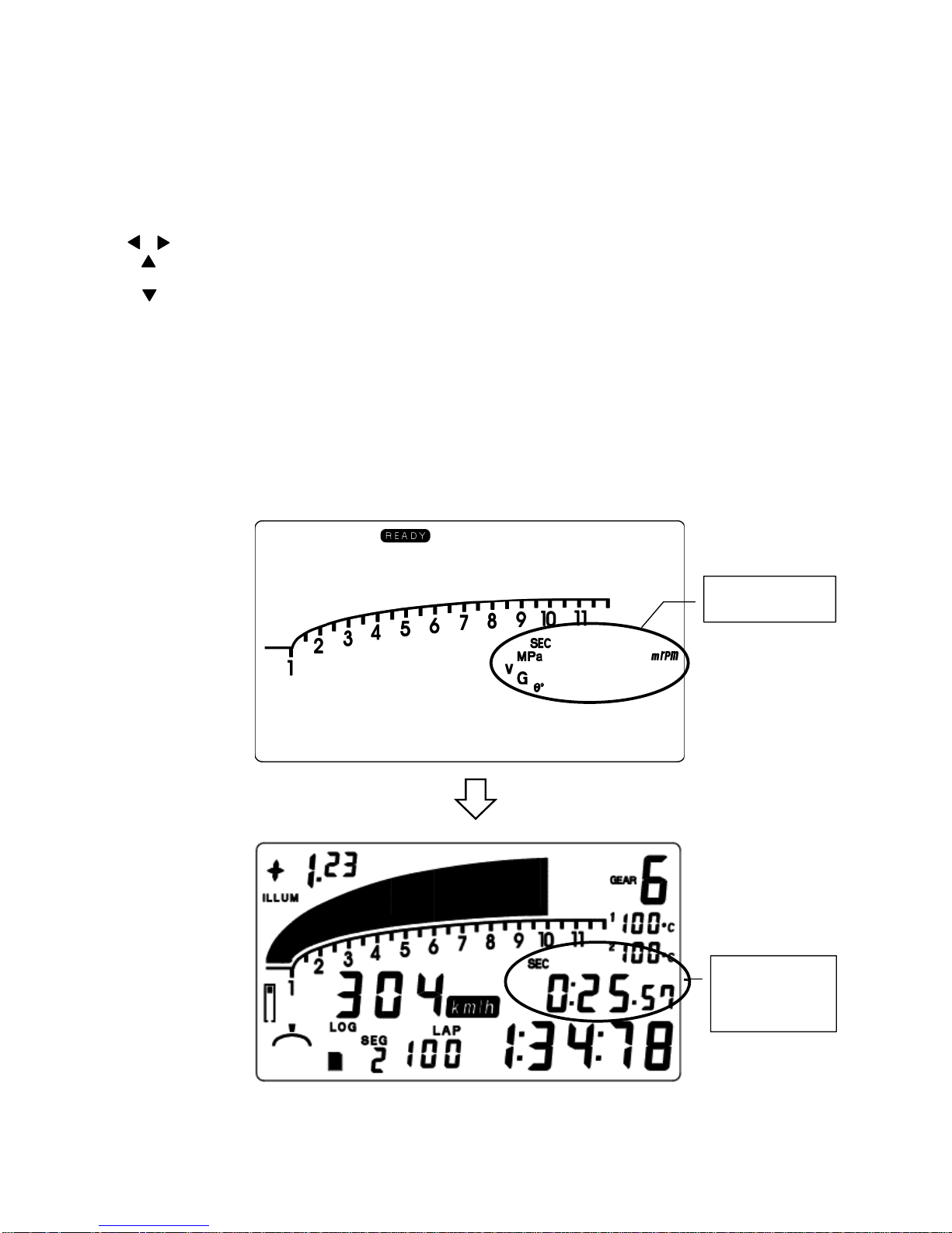
9) Selecting the Data Item to Display During Driving
The data item for display during driving can be selected as shown below.
SEC Current segment time
1Mpa: Press1 pressure
2Mpa: Press2 pressure
V Alternately displays the battery pack and external battery voltages.
G Lateral G value
G Longitudinal G value
θ Steering angle
m Distance driven
rpm Current RPM
Press the SET key. The currently selected item flashes. Press the SET key until the
item you want to display is flashing. Press the CLEAR key or wait for a few seconds.
Then the flashing stops and the item to display is determined.
Select the item to
display.
Current segment
time is displayed
when “SEC” was
selected.
-51-
Page 53
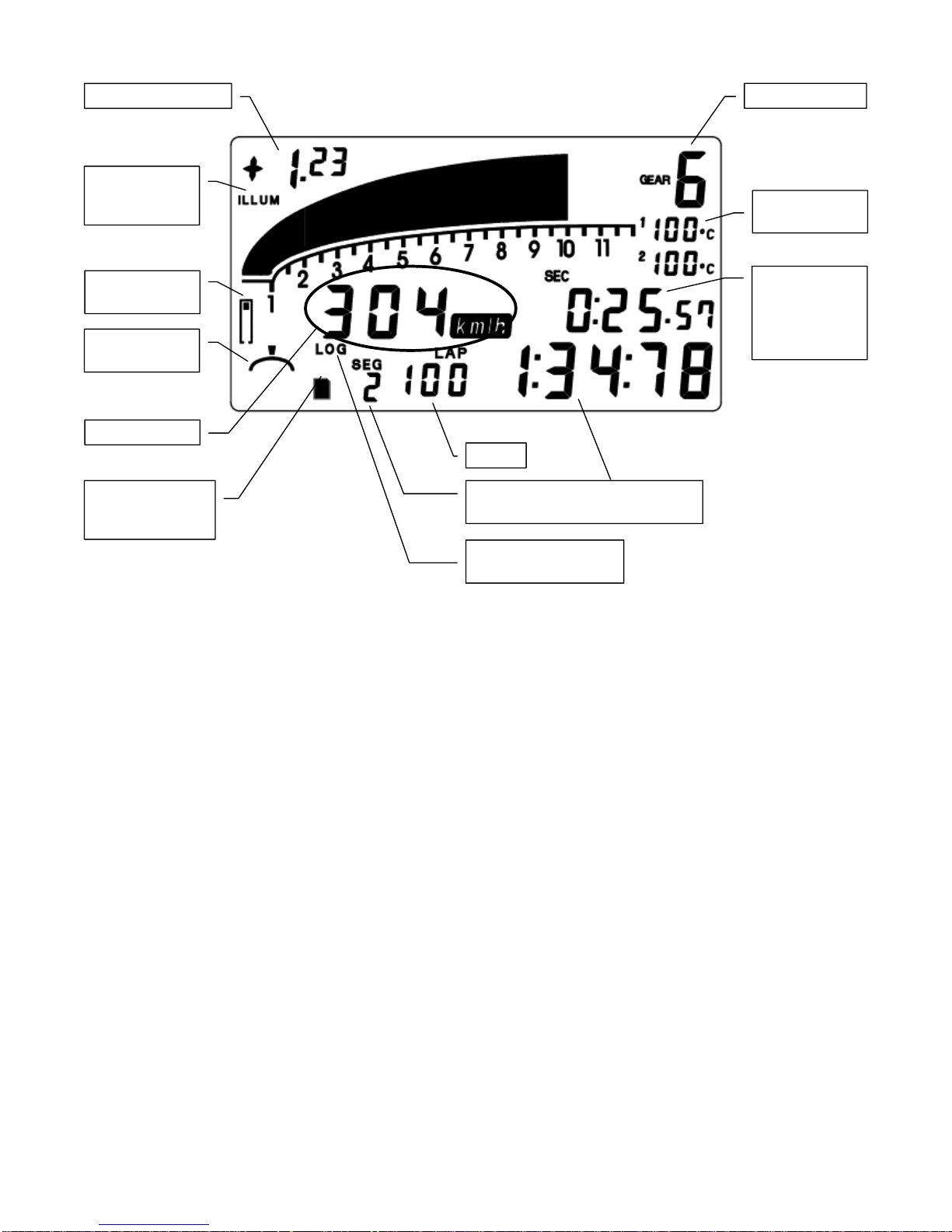
10) Monitoring Data during Driving
Current gear No.
Current
temperature
Throttle position
Steering angel
Wheel speed
Turns on when a
memory card is
inserted.
Lap No.
Most recent section No. and
section time or lap time
Turns on when
logging is in progress.
Current
segment time is
displayed when
“SEC” was
selected.
Turns on when
the backlight is
on.
Lap time difference
-52-
Page 54
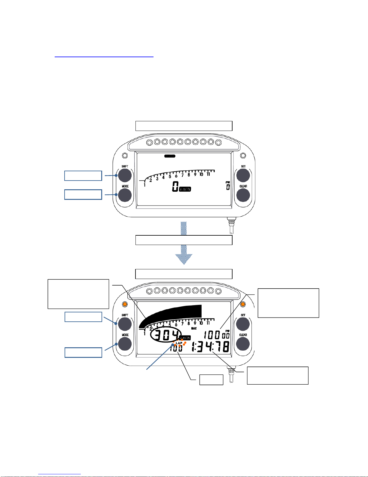
11) Reviewing Data from the Display
*The temperature is not displayed when the temperature sensor is not connected to the main unit.
①
Lap time and best lap display
1.Confirm the [READY] is displayed. Press the MODE key or the SHIFT key. The
LAP comment flashes and the lap time is displayed. Press the SHIFT key to
display the lap times in ascending order and the MODE key to display them in
descending order.
MODE key
Press the SHIFT key or MODE key.
[READY] display screen
Lap time display
Check the data in
ascending order.
SHIFT key
MODE key
Check the data in
descending order.
The LAP indicator
flashes and the lap
time is displayed.
A
lternately displays
the wheel speed Max.
and Min. for the
displayed lap.
A
lternately displays
the RPM Max. and
Min. for the displayed
lap.
Lap time for the
currently displayed lap
Lap No.
SHIFT key
-53-
Page 55
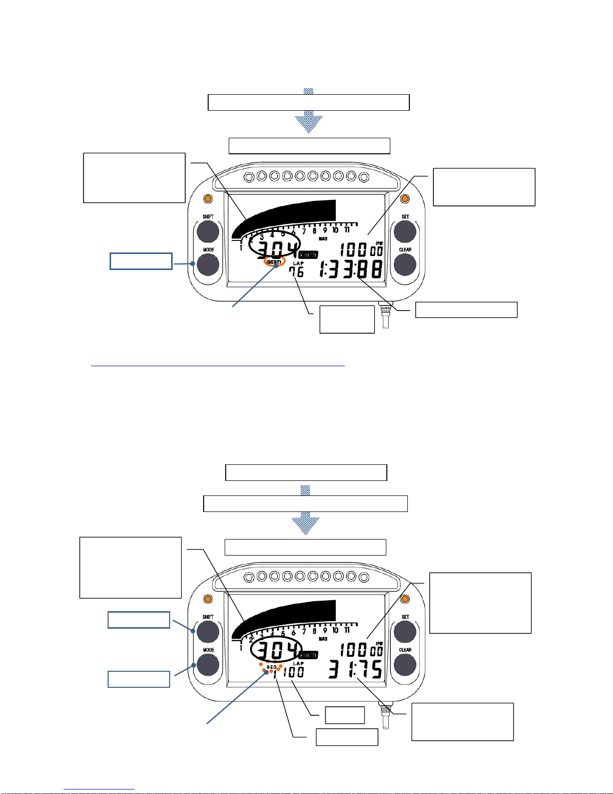
2. To display the best lap, press and hold the MODE key for 3 seconds. The (BEST)
comment turns on and the best lap is displayed. Press the MODE key or SHIFT
key to return to the lap time display in the procedure 1.
Press and hold the MODE key for 3 seconds.
Best lap display
MODE key
The (BEST) indicato
r
turns on and the best lap
is displayed.
Lap No. o
f
the best lap
Best lap time
A
lternately displays
the wheel speed Max.
and Min. for the best
lap.
A
lternately displays
the RPM Max. and
Min. for the best lap.
②
Segment time and best segment time display
1. When the lap time is displayed, press the MODE key and SHIFT key at the same
time. The SEG indicator flashes and the display changes to the segment time
display. The segment times for each lap can be displayed in descending order
by pressing the MODE key and in ascending order by pressing the SHIFT key.
Lap time display
-54-
Displays the segment time.
A
lternately displays
the RPM Max. and
Min. for the displayed
segment of the
displayed lap.
SHIFT key
Check the data in
descending order.
MODE key
Lap No.
Segment No.
Segment time for the
displayed segment o
f
the displayed lap
Check the data in
ascending order.
A
lternately displays
the wheel speed Max.
and Min. for the
displayed segment o
f
the displayed lap.
The SEC indicato
r
flashes and the segment
time is dis
play
ed.
Press the MODE key and SHIFT key together.
Page 56
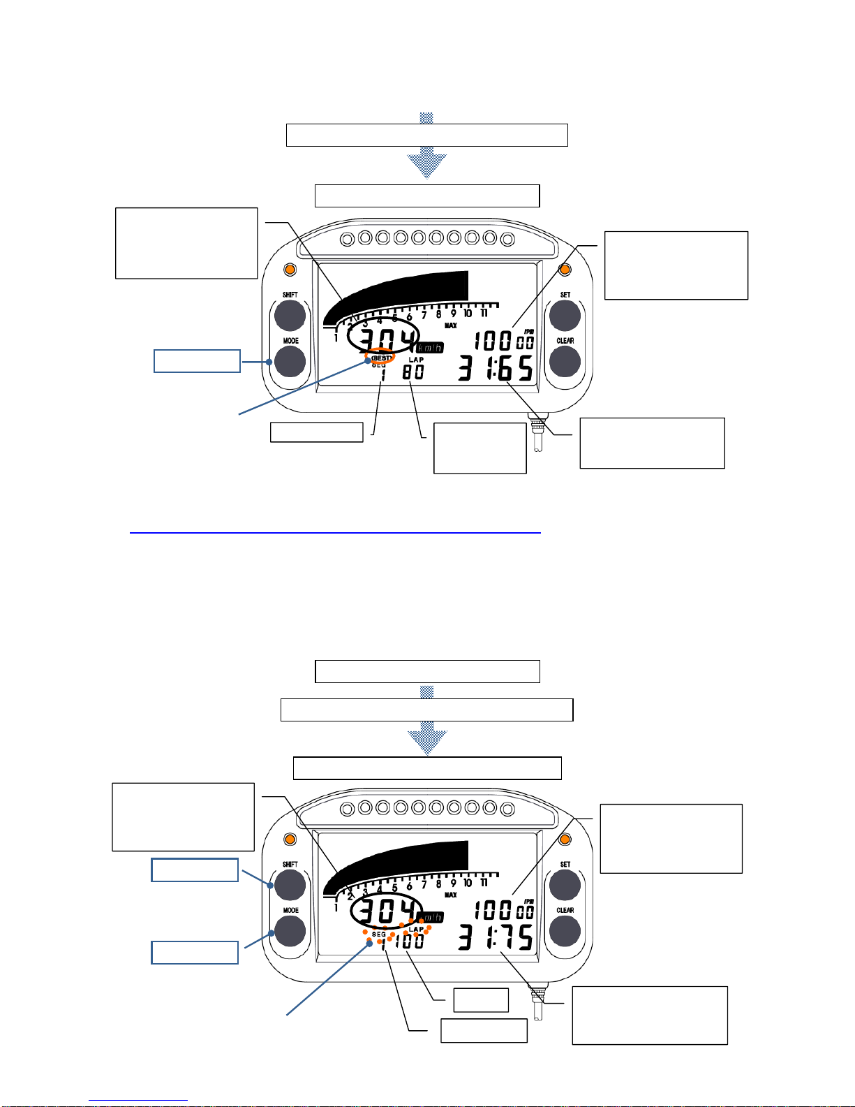
2. To display the best segment time among all laps for the section No. currently
displayed, press and hold the MODE key for 3 seconds. The (BEST) indicator
turns on and the best segment time is displayed.
Press and hold the MODE key for 3 seconds.
Displays the best segment time.
MODE key
Lap No. of the
best segment
time
The (BEST) indicato
r
turns on and the best
segment time is
displayed.
Segment No.
A
lternately displays
the RPM Max. and
Min. for the best
segment time.
A
lternately displays
the wheel speed Max.
and Min. for the best
segment time.
Best segment time fo
r
the displayed segment
No.
③
Same segment times and best segment time display
1. When the section time is displayed, press the MODE key and SHIFT key at the
same time. The LAP and SEG indicators flash and the display changes to the
display of times for the same section. The section times from each lap for the
currently displayed section only can be displayed in descending order by
pressing the MODE key and in ascending order by pressing the SHIFT key.
Displays the times for the same segment.
Press the MODE key and SHIFT key together.
Section time display
-55-
SHIFT key
MODE key
Check the data in
descending order.
Lap No.
Segment No.
Time for the same
segment as the segment
currently displayed
A
lternately displays
the wheel speed Max.
and Min. for the
displayed segment
A
lternately displays
the RPM Max. and
Min. for the displayed
segment.
Check the data in
ascending order.
The LAP and SEC indicators
flash and the times for the
same segment are displayed.
Page 57
2. In the same way as ②-2., to display the best section time among all laps for the
section No. currently displayed, press and hold the MODE key for 3 seconds.
The (BEST) indicator turns on and the best section time is displayed. Press the
MODE key or SHIFT key to return to the lap time display. (Refer to the figure in
②-2.)
12) How to delete Driving Data
<Erasing the driving data for 1 lap>
1. Verify that [READY] is displayed on the display screen.
2. Press the MODE key or SHIFT key and display the lap data to erase.
3. Press and hold the SET key and CLEAR key at the same time for 3 seconds. The
lap time display changes to [0:00:00] and the data is invalidated.
<Erasing all driving data>
1. Verify that [READY] is displayed on the display screen.
2. Press and hold the SET key and CLEAR key at the same time for 3 seconds. The
display momentarily turns off and all lap data is erased.
13) How to Initialize the Parameter Settings
1. Verify that [READY] is displayed on the display screen. If it is not displayed, press
the CLEAR key to display it.
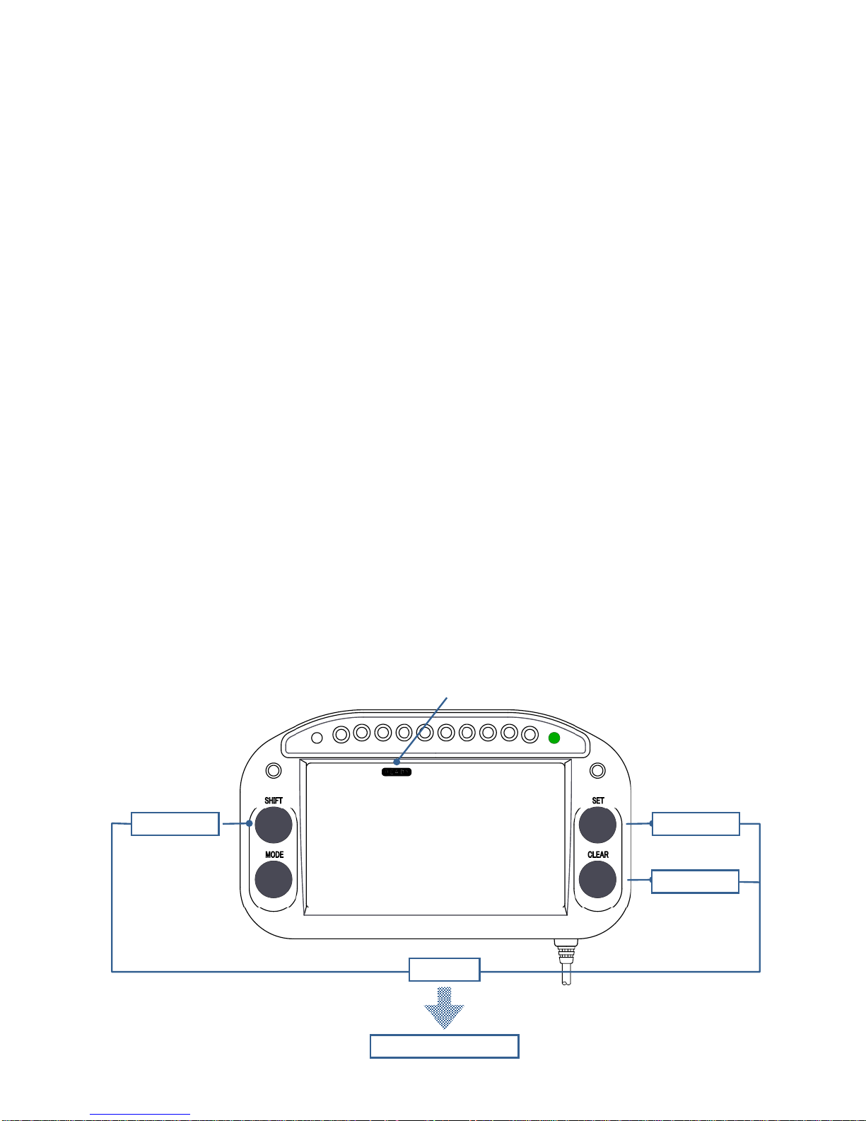
2. Press and hold the SHIFT key, SET key, and CLEAR key at the same time for 3
seconds. Verify that the display momentarily turns off.
SHIFTキー
3 seconds
+
MODEキー
CLEAR key
SHIFTキー
SET key SHIFT key
READY display
Display turns off.
-56-
Page 58

1266-1, Ueno, Matsuyama,
Ehime, JAPAN 791-1136
Phone: 089-963-3301
Fax: 089-963-1308
URL http://www.percul.co.jp
PERCUL CORPORATION
-1-
 Loading...