


Electromechanical Box Tripod
Turnstile with Automatic
Anti-Panic Arms
TTD-08A
Assembly and Operation Manual

CONTENTS
1 APPLICATION ............................................................................................................ 3
2 OPERATION CONDITIONS ........................................................................................ 3
3 TECHNICAL SPECIFICATIONS ................................................................................. 4
4 DELIVERY SET .......................................................................................................... 5
4.1 Standard delivery set ............................................................................................. 5
4.2 Optional equipment supplied on request ............................................................... 5
5 PRODUCT DESCRIPTION ......................................................................................... 6
5.1 Main features ......................................................................................................... 6
5.2 Design ................................................................................................................... 6
5.2.1 Turnstile housing ............................................................................................ 7
5.2.2 Indication modules ......................................................................................... 8
5.2.3 RC panel ........................................................................................................ 8
5.2.4 Control Logic Board ........................................................................................ 9
5.2.5 Parameters of control signals ....................................................................... 11
5.2.6 Control modes of the turnstile ....................................................................... 12
5.2.7 Algorithm of the control mechanism ............................................................. 13
5.3 Control devices of the turnstile ............................................................................ 14
5.3.1 Connection of the RC panel ......................................................................... 14
5.3.2 Emergency opening device Fire Alarm ......................................................... 15
5.3.3 Control of the turnstile in ACS ...................................................................... 15
5.4 Additional devices connectable to the turnstile .................................................... 16
5.4.1 Relay outputs ............................................................................................... 16
5.4.2 ID and siren .................................................................................................. 17
5.4.3 Remote indicators ........................................................................................ 17
5.5 Operation contingencies and response ............................................................... 18
6 MARKING AND PACKAGING ................................................................................... 19
7 SAFETY REQUIREMENTS ...................................................................................... 20
7.1 Installation safety requirements ........................................................................... 20
7.2 Operation safety requirements ............................................................................ 20
8 INSTALLATION INSTRUCTIONS ............................................................................. 21
8.1 Installation details ................................................................................................ 21
8.2 Installation tools ................................................................................................... 23
8.3 Length of cables .................................................................................................. 23
8.4 Connection layout of the tur nsti le and opt ional equip ment ............................... 24
8.5 Installation procedure ......................................................................................... 26
9 OPERATION INSTRUCTI ONS ................................................................................ 28
9.1 Power-up ............................................................................................................. 28
9.2 Operating modes of the turnstile at pulse contr ol mode ................................... 28
9.3 Operating modes of the turnstile at potential control mode ................................. 30
9.4 Actions in emergency .......................................................................................... 30
9.5 Troubleshooting ................................................................................................... 31
10 MAINTENANCE ........................................................................................................ 32
11 TRANSPORTATION AND STO RAGE ..................................................................... 33
Appendix 1. Control signal algorithm at pulse control mode .............................................. 34
Appendix 2. Control signal algorithm at potential control mode ......................................... 35

TTD-08A Electromechanical Box Tripod Turnstile
Dear Customer,
Thank you for purchasing the PERCo turnstile. Please follow the instructions
given in the Manual carefully, and this quality product will provide many years
of trouble-free use.
Assembly and Operation Manual (hereinafter - the Manual) for the TTD-08A
electromechanical tripod turnstile with automatic anti-panic folding arms contains
data that is necessary for the most full use of operat ing advantages of the turnst ile as well
as chapters on packaging, installation and maintenance.
Only qualified personnel, following the instructions of this Manual, must carry out
installation and maintenance
Abbreviations:
• ACS — access control system;
• RC panel – remote control panel;
• WRC – wireless control panel;
• CLB – control logic board.
1 APPLICATION
The TTD-08A electromechanical box tripod turnstile with automatic anti-pani c folding arms
(hereinafter - the turnstile) is desi gned for managing pedestr ian flows at entrance points of
industrial facilities, banks, administrative buildings, r etail outlets, railway ter minals, airports
providing free passageway in emergency situations. Housing of the turnstile is made of
stainless steel. Outdoor application is allowed.
To ensure fast and convenient passage it is recommended to install one turnst ile per 500
people working the same shift, and on the basis of maximum working load
30 persons / min See Chapter 3 for information on the throughput capacity of the turnstile.
2 OPERATION CONDITIONS
The turnstile with regard to resistance to environmental exposure complies with
GOST15150-69, category N1 (for an outdoor application).
Operation of the turnstile is allowed at ambient air temperature from –20°C to +45°C
(when used under the canopy – to + 55°C) and at relative air humidity of up to 80% at
+25°C.
3

Assembly & Operation Manual
3 TECHNICAL SPECIFICATIONS
Operating voltage .............................................................................................. 12±1.2VDC
Consumption current ........................................................................................... max. 6.0 A
Power consumption .......................................................................................... max. 72 W
Throughput rate in a single passage mode .................................................. 30 persons/min
Throughput rate in a free passage mode ..................................................... 60 persons/min
Passage width ......................................................................................................... 560 mm
Barrier arm rotation force ..................................................................................... max. 3 kgf
RC panel cable length
Ingress Protection Rating .......................................................................... IP44 (EN 60529)
Electric shock protection class ...................................................................... III (IEC 61140)
Mean time to failure .................................................................... min. 1,500,000 passages
Mean lifetime ........................................................................................................... 8 years
Overall dimensions (L × W × H) ......................................................... 1166×750×1016 mm
2
...................................................................................... min. 6.6 m
1
Net weight of the turnstile .................................................................................. max. 70 kg
Figure 1 – Overall dimensions of the TTD-08A turnstile
1
The power consumption can rise to 72W within 5 sec. after power up or at taking off the Fire
Alarm signal. In normal state the power consumption is no more than 30 W.
2
Max. allowed cable length – 40 m (sup plied on request ).
4

4 DELIVERY SET
4.1 Standard delivery set
Basic equipment:
Turnstile housing with hub and barrier arms ............................................................ 1
S2.5 allen key to a housing top cover ...................................................................... 1
RC panel with cable ................................................................................................. 1
Installation tools:
Self-adhesive cab le tie m ount ................................................................................ 3
Nylon cable tie 100 mm ......................................................................................... 6
Self-adhesive PCB pillars FSS-5 .............................................................................. 4
Technical documentation:
Certificate ............................................................................................................... 1
Assembly and operation ma nual ........................................................................... 1
Package:
Box .......................................................................................................................... 1
TTD-08A Electromechanical Box Tripod Turnstile
4.2 Optional equipment supplied on request
Power supply unit
WRC kit
2
..................................................................................................................... 1
SORMAT anchor PFG IR 10-15 .................................................................................. 4
1
, 12VDC/6A ................................................................................... 1
1
The power supply source must have load current min. 6A within 5 sec.
2
WRC kit consists of a receiver and transmitters (tags) with operation range up to 40 m.
5

Assembly & Operation Manual
5 PRODUCT DESCRIPTION
5.1 Main features
• The turnstile is designed either for indoor application or outdoor (see Clause 2).
Turnstile housing is produced from high quality stainless steel with ABS plastic
covers.
• The turnstile plastic side covers are radio transparent that allows concealed
mounting of the ACS readers inside the turnstile housing.
• The turnstile can be operated from the RC panel or WRC as well as from an ACS.
• The turnstile is equipped with automatic anti-panic folding arm s. Automatically free
of passageway is performed by bringing the barrier arm into vertical position at a
power loss or by alarm signal. A purpose-designed «Fire alarm» control input is
intended for opening the turnstile at the fire alarm command or from emergency
opening button.
• The turnstile houses 2 LED indication displays intended for status and passage
direction indication. Besides, the turnstile has an extra indication of passage
direction on its side posts.
• The turnstile has outputs for connection of remote indicators.
• The turnstile has relay outputs for connection of an intr usion detect or and a siren.
• There are two modes for the turnstile control — a pulse control mode and a
potential control mode.
• After each passage the turnstile provides autom atic complete rotation of the barrier
arm to home position, i.e. automatic reset.
• After the turn of barrier arm for more than 60º angle its reverse rot ation is bloc ked.
• Smoothness of reset and quiet operation are ensured by a damper.
• The optical arm rotation sensors are built into the turnstile housing to ensure
accurate count of inputs to an ACS.
• The turnstile is supplied with safe voltage — maximum 14V.
• Galvanic decoupling of the outputs ensures noise-immunity of the turnstile
electronics.
• Installed in a line several turnstile housings form a secured passage without
installation of extra guide barriers.
5.2 Design
The design of the turnstile is shown in Fig. 2. Numbers in brackets corres pond to Fig. 2 of
this Manual. The overall dimensions of the turnstile housing are shown in Fig. 1.
The turnstile comprises a turnstile housing (1), hub with three barrier arms (4), RC p anel
(12). Fastening of barrier arms to the hub is hinged. The turnstile housing is fixed to floor
with 4 anchor bolts through holes in the turnstile housing base (2).
6

TTD-08A Electromechanical Box Tripod Turnstile
Figure 2 – TTD-08A turnstile overall view
Standard delivery set:
1 – frame; 2 – base; 3 – top cover; (items 1-3 f orm turnstile housing);
4 – drag screw for the top cover; 5 – folding arm;
6, 7 – turnstile housing sidewalls; 8, 9 – side covers with indication modules;
10, 11 – direction indicators; 12 – RC panel with cable
Not included in the standard delivery set:
13 – power cable; 14 – emergency opening device (Fire Alarm) cable;
15 – ACS connection cable.
5.2.1 Turnstile housing
Internal elements of the turnstile housing are accesse d through the removable top cover
(3). Fastening of the cap to the housing is accomplished with the help of driver screw (4).
During operation of the turnstile top cover has to be locked. Under the top cover t here is a
bracket with control panel PERCo-CLB.140 (further – control panel) and remote connector
block XS1.
7

Assembly & Operation Manual
–
green indicator of authorized passage (arrow)
Both front sides of the turnstile housing feature indication modu les (8, 9). Top covers are
fixed fast on side walls (6, 7). Under side walls there are turnstile indication boards. On
side walls there are extra indicators of passage direction, passage indication boards are
located under them. When removing side walls, assembled with top cover s, there f orms an
access to four holes in the post base (2), in order to fix the turnstile to the mounting
surface.
To access the rotation unit of barrier arms, it is necessary to remove the bracket of control
board.
Rotation unit consists of (see Fig. 16):
• control mechanism with optic sensors of ba rrier arms rotation angle, which helps to
register the passage correctly;
• rotation mechanism, which includes:
o barrier arms resetting unit (pusher, spring and roller), providing automatic
reset of barrier arms to the home position after every passage;
o damper, providing smooth and soft-running work of rotary mechanism;
o locking device, preventing the possibility of an unauthorized passage;
• electromechanical device for emergency opening of the passage way.
5.2.2 Indication modules
To inform about a current status and a set module of the turnstile work both front sides of
the turnstile housing feature indication modules ( see Fig. 3). The indication module has 3
mnemonic indicators:
– red indicat or of passage denial (cross)
– white indicator, showing the card presentation spot
Figure 3 – Indication module
5.2.3 RC panel
The RC panel (12) is designed as a small deskt op device with a shock-proof ABS plastic
case and is intended for setting and indicating operating modes when the turnstile is
operated manually. The RC panel overall view is shown in Fig. 4.
There are three control buttons on the RC front panel intended for setting the turnstile
operating modes. The LED indicators are located abo ve the buttons. The m iddle butto n on
the RC panel (hereinafter — the STOP button) is intended to set the turnstile to the
“Always locked” mode. The left (LEFT) and the right (RIGHT) buttons are intended to
unlock the turnstile for passage in the chosen direction.
Control commands and corresponding indication on RC panel for impulse and potential
modes are indicated in Table 5 and 6.
The RC panel is connected to the CLB with a mult icore cable via the XS1 connector block
(see Fig. 13).
8

TTD-08A Electromechanical Box Tripod Turnstile
Figure 4 – RC panel overall view
1, 2, 3 – buttons LEFT, RIGHT, STOP for setting the passage m ode;
4, 5 – green indicators «Left», «Right»;
6 – red indicator «Stop», 7 – RC cable
5.2.4 Control Logic Board
Turnstile control board (see Fig. 5) and remote connector block XS1 are fixed on the
bracket, located inside the post. To access the board it is necessary to remove the
turnstile cover, following the instructions of Clause 6.
Figure 5 – Control Logic Board (CLB)
9

Assembly & Operation Manual
№
Item
Function of the contact
Connector blocks of the CLB.140
XT1L (In)
1
+12V
Output of power supply for ID
2
Detector
Input for connections ID
3
GND
Common contact for connections ID
4
Fire Alarm
5
GND
6
GND
Common
7
Unlock A
8
Stop
9
Unlock B
10
Led A
11
Led Stop
12
Led B
XT1H (Out)
1
GND
2
+12V
3
Alarm 1
4
Alarm 2
5
Common
Common contact for PASS A, PASS B signals
6
Pass A
PASS A relay contact (passage in direction A)
7
Pass B
PASS A relay contact (passage in direction B)
9
Ready
Relay output READY (turnstile readiness)
10
Det Out
Relay output DET OUT (retransmission of intrusion detector condition)
XT3 (+12VDC)
1
+12V
2
GND
XT4 (Light A)
1
NO
2 C 3
NC
XT5 (Light B)
5
NO
6
C
7
NC
Out connector block XS1 on the bracket
1
+12V
2
GND
3
Fire Alarm
4
GND
5
GND
Common
6
Unlock A
7
Stop
8
Unlock B
9
Led A
10
Led Stop
11
Led B
12
Common
Common contact for PASS A, PASS B signals
13
Pass A
PASS A relay contact (passage in direction A)
14
Pass B
PASS A relay contact (passage in direction B)
Table 1 – Contacts of the connector blocks
Input for emergency opening device
Inputs for turnstile control
Indication outputs of RC panel
Output of power supply for additional devices
Outputs for connections siren
Connection of external power supply
Light A relay contacts – connection of remote indicator for direction A
Light B relay contacts – connection of remote indicator for direction B
Connection of external power supply
Input for emergency opening device
Inputs for turnstile control
Indication outputs of RC panel
10

TTD-08A Electromechanical Box Tripod Turnstile
On control board there is a microcontroller, which pro cesses incoming control commands
(inputs Unlock A, Stop, Unlock B and Fire Alarm), traces the condition of barrier arms
optical sensors and basing on received data generat es commands on control unit of the
turnstile. Besides, microcontroller generates signals on out puts: for indication on RC pan el
(outputs Led A, Led Stop and Led B), for outer indication (outputs Light A, Light B), for
passing in a corresponding direction (PASS A and PASS B), f or turnstile readiness to run
the command (Ready), for alarm (Alarm), to retransmit the signal of intrusion detector
condition (Det Out).
The CLB (Fig. 5) includes:
• X1 (LED), X2 (SENS), X3 (MOTOR) connectors to connec t the indication module,
optical arm rotation sensors and control me chanism with a locking device (from the
X1, X2, X3 connectors with the turnstile cable).
• XT1.L (In) – connector block to connect the RC panel / WRC / AC S contr oller input s
as well as an emergency opening device (Fire Alarm) and intrusion detector
(see Clauses 5.3.1, 5.3.2, 5.4.1).
• XT1.H (Out) – connector block to connect a siren and ACS outputs, providing the
turnstile status data to the ACS controller (see Clause 5.4.1).
• XT3 (+12VDC) – connector block to connect the turnstile power supply.
• XT4 (Light A) and XT5 (Light B) – connector blocks to connect “open/closed”
remote indicators, one indicator per each direction (see Clause 5.4.3).
• XT6 (AntiPanic) – connector block to connect the electromagnet of automatic
anti-panic opening device.
• J1 – connector to select the turnstile control mode, the jumper is fixed — the pulse
control mode, the jumper is not fixed — the potential control mode. The jumper is
fixed at the factory before the delivery (see Clause 5.2.6).
• J2 – connector for programming.
• Power – power LED indicator on the control board.
For convenience, connection contacts of turnstile pow er supply and turnstile control units
are set on the bracket on connector block XS1. Connection is conducted out in
accordance to the connection diagram of the turnstile and optional equipment (see
Fig. 13). Electric power supply is carried out through the power cable (13).
5.2.5 Parameters of control signals
The turnstile is operated by input of a low-level signal t o the XS1 connector block contacts
“Unlock A”, “Unlock B” and “Stop” relatively to the “GND” contact . As the control element
there can be used a normally open relay contac t or a circuit with open collector output at
that. At the emergency the turnstile control is carried out by r emoving of a low-level signal
from the “Fire Alarm” contact relatively to the “GND” contact. As the control element there
can be used a normally closed relay contact or a circuit with open collector out put at that
(Fig. 6 and 7).
Emergency unblocking of the turnstile is carried out by removing of a low-lev el relatively to
the “GND” contact signal from the “Fire Alarm” contact. As a control element t here can be
used a normally closed relay contact or a circuit with open collector output at that. All
turnstile control commands coming to other outputs are ignored (see Clause 5.3.2).
During the low signal injection on Fire Alarm output directions switch to the mode
according to signal levels on inputs Unlock A, Unlock B and Stop.
Activation of intrusion detector is controlled by removing of a low-level relatively to the
“GND” contact signal from the “Fire Alarm” contact. As a control element there can be
used a normally closed relay contact or a circuit with open collector output at that.
11

Assembly & Operation Manual
level signal at all input contacts (“Unlock A”, “Stop”, Unlock
“+ 5 V” are used
Installation and removal of the jumper is to be done only when the turnstile is
switched off.
Note:
For generation of highB”, “Fire Alarm” and “Detector”) 2kOhm resistors conn ected to the power su pply bus
Figure 6 – ACS control element - normally open relay contact
Figure 7 – ACS control element - circuit with open-collector output
The control element must provide the following signal characteristics:
the relay contact as the control element:
minimum switched current .......................................................... no more than 2 mA
closed contact resistance
(with the resistance of the connected cable) ........................ no more than 300 Ohm
the circuit with open-collector output as the control element:
voltage at the closed contact
(low - level signal at the CLB input) ............................................ no more than 0.8 V
5.2.6 Control modes of the turnstile
There can be two control modes of the turnstile: pulse and potential. In both modes
turnstile control is conducted by command issuing (namely by combination of control
signals) on operational control inputs: Unlock A, Stop and Unlock B and special control
input Fire Alarm. Depending on a chosen mode the procedure of command issuing
changes (see table 5 and 6).
Warning!
12

TTD-08A Electromechanical Box Tripod Turnstile
during activation of relay
output PASS A / PASS B of corresponding direction.
The control mode is set by removal / installation of the jumper on a J1 conne c t or on control
board. The J1 connector location is shown in Fig. 5. An installed jumper corresponds to
the pulse control mode. In order to switch to potential mode, uninstall the jumper. The
change of control mode will take place after switching on the turnstile.
Pulse control mode
The mode is used to control the turnstile with RC panel, WRC and CLB, outputs of which
support pulse control mode.
Duration of control signal during command issuing on operational control inputs should be
not less than 100mc. The passage waiting time is 5 seconds and it doesn’t depend on
duration of control signal (impulse).
Description of turnstile work in pulse control mode is described in Table 5 Procedure of
command issuing is described in Appendix 1.
By removal of low-level signal from special control input Fire Alarm, turnstile switches to
Fire Alarm, mode and therewith all incoming commands of turnstile control are ignored
(see Clause 5.3.2).
During low-level signal issuing at the input Fire Alarm command «Passage Denial» is sent
and turnstile rotary mechanism is blocked.
Potential control mode
The mode is used to control the turnstile with CLB, outputs of which support potential
control mode.
Duration of control signal during command issuing on operational control inputs should be
not less than 100mc.
The passage waiting time equals the duration of control signal: if by the moment of the
passage in authorized direction at the entrance of this direction there is a low-level signal,
then the turnstile will stay open in this direction.
At the low-level signal inputting to t he “Stop” input, both directions will lock for t he time of
the signal duration regardless of the signal strength at the inputs “Unlock A” and “Unlock
B”. By the removal of a low-level signal from the “Stop” input, t he directions will set to the
modes according to the signal strength at the inputs “Unlock A” and “Unlock B”.
Description of turnstile work in potential control mode is described in Table 6. Procedure of
command issuing is described in Appendix 2.
Note:
To organize single passages in potential control mode it is advisable to remove lowlevel control signal from control input Unlock A/ Unlock B
5.2.7 Algorithm of the control mechanism
Procedure of turnstile work in the pulse control mode in case of a single pass age in one of
directions:
1. From control unit (RC panel, WRC, ACS) on control board inputs comes a
command (combination of control commands) for execut ion of a single passage in
one of directions.
2. Microcontroller, fixed on the control board, processes the received signal
combination and forms a command to the turnstile control unit to unblock t he rotary
mechanism. Turnstiles hold time counting starts in the blocked mode.
3. Control mechanism unlocks the rotary mechanism for the rotation in a chosen
direction. Passage in this direction becomes possible.
13

Assembly & Operation Manual
At the parallel connection of the above devices to the turnstile the superposition
from them may occur. In that case the turnstile response will
conform to response to the obtained combination of input signals. (App. 1 and 2).
4. After the passage is complete, barrier arms rotation angle is monitored by
microcontroller with optical sensors of control mechanism. With rotation angle of
more than 67° the act of passage is registered. One of relay outputs PASS A or
PASS B, according to the direction of the passage, becomes active. Microcontroller
forms the instruction to the control mechanism for blocking the turnstile rotation
mechanism.
5. After the passage is complete, i.e. when barrier arms are reset to the closed
position (120° rotation), turnstile rotation mechanism is blocked. Relay output
PASS A / PASS B becomes normal.
6. If barrier arms rotation hasn’t started, then the command for blocking rotation
mechanism is formed as hold time passes in unblocked mode (5 seconds from
receiving the instruction by default).
7. Turnst ile is ready f or next passage.
5.3 Control devices of the turnstile
The turnstile can be operated from the following control devices:
• the RC panel;
• the WRC;
• the ACS controller.
The above devices can be connected to the turnstile as follows:
• any device separately;
• in any combination with each other;
• all devices simultaneously (in parallel).
Note:
of the control signals
5.3.1 Connection of the RC panel
The RC panel is connected to the contacts GND, Unlock A, Stop, Unlock B, Led A,
Led Stop and Led B of the XS1 connector block in accordance to the connection layout o f
the turnstile (see Fig. 13).
Figure 8 – Standard RC-panel orientation regarding IP-Stile
14

TTD-08A Electromechanical Box Tripod Turnstile
of the
the XS1 connector block.
RC-panel orientation
Standard
Reverse
5
GND
black
black
6
Unlock A
white
green
7
Stop
blue
blue
8
Unlock B
green
white
9
Led A
yellow
red
10
Led Stop
orange
orange
11
Led B
red
yellow
Standard orientation of RC panel in regard to the housing is shown in Fig. 8. If working
space of the operator is located on the opposit e side of the housing, then for convenience
of operation it is necessary to swap RC pan el cables, connected t o contacts Unlock A and
Unlock B, as well as Led A and Led B correspondingly (see Table 2).
Note:
The WRC is connected to the contacts GND, Unlock A, Stop and Unlock B
XS1 connector block. Power sup ply of the WRC is connected to the contact +12V of
Table 2 – RC-cable connection to the XS1 connector block
contacts for standard and reverse RC-panel orientation
№ Contact
5.3.2 Emergency opening device Fire Alarm
The emergency opening device is connected to the contacts “ Fire Alarm” and “GND” of the
XS1 connector block in accordance with the connection layout (see Fig. 13).
If the “Fire Alarm” input is not used, it is necessary to set a jumper between the contacts
“Fire Alarm” and “GND”. This jumper is preset at the factory.
During release of control signal on Fire Alarm input, turnstile switches to the emergency
Fire Alarm passageway opening. In this mode all incoming turnstile control signals are
disregarded. Turnstile rotation mechanism is blocked for rotation in both directions. Central
barrier arm falls down automatically by gravity and takes a vertical position which opens
the passageway. The following indication in both directions is displayed simultaneously on
indication modules: alternate switching on of green (for 1.25 sec) and red (for 0.25 sec)
turnstile indicators.
If signal Fire Alarm comes on the turnstile during the passage, t hen on indication blocks
appears an indication of Fire Alarm mode, but rotation mechanism blocking and passa ge
emergency opening will take place only after resetting of barrier arm to its home position.
After release of control signal Fire Alarm on indication modules appears red indicator of
passage denial and turnstile switches to the sleep mode with a dropped barrier. To
proceed with the work, a barrier arm has to be manually set in horizontal posi tion, where it
fixes.
5.3.3 Control of the turnstile in ACS
Turnstile can be used as optional equipment while wor king as a part of ACS. Turnstile is
provided for installation of built-in access card readers under plastic side cover s.
The ACS controller outputs are connected to the contacts GND, Unlock A, Stop and
Unlock B of the XS1 connector block.
15

Assembly & Operation Manual
The ACS controller inputs are connected to the contacts Common, PASS A, PASS B of
the XS1 connector block and to the contacts Ready and Det Out of the XT1.H connector
block.
Pin assignments of the connector blocks are given in Fig. 13.
5.4 Additional devices connectable to the turnstile
5.4.1 Relay outputs
Connection of control board to relay outputs is done through corresponding contacts of
connector block XT1.H. The following relay outputs are installed:
• ALARM: contacts Alarm 1 and Alarm 2 (see Claus e 5.4.2),
• PASS A: contacts Pass A and Common (see Clause 5.2.7),
• PASS B: contacts Pass B and Common (see Clause 5.2.7),
• READY: contacts Ready and Common (see Clause 5.5),
• DETECTOR: contacts Det Out and Common (see Clause 5.4.2).
Contacts Pass A, Pass B and Common are also located on conne ctor block XS1.
Relays have normally open contacts. Therewith comm on for t hose relays cont act Common
is not connected with the negative of turnstil e power supply (ga lvanically isolated). I n initial
(standard) condition with a switched on power supply relay contacts PASS A, PASS B,
READY and DETECTOR are closed (relay coil gets energized), and relay contacts
ALARM are opened (relay coil gets deenergized).
Relay winding energizing can be identified by lighting up of corresponding red LED,
installed on control board near the corresponding relay (see Fig. 5).
Figure 9 – Output cascades for PASS A, PASS B, Ready, Det Out and Alar m
The output cascades for PASS A, PASS B, Ready, Det Out and Alarm are the contacts
with the following signal characteristics (Fig. 9):
maximum commutation voltage ...................................................................... 42 VDC
maximum switched current ............................................................................... 0.25 A
closed contact resistance ...................................................... no more than 0.15 Ohm
16

TTD-08A Electromechanical Box Tripod Turnstile
Installation of intrusion detector inside the turnstile housing is not anticipated.
if the
rotating mechanism of the turnstile is blocked in one of directions or was blocked
less than 3 seconds ago.
5.4.2 ID and siren
Warning!
Intrusion detector is connected to contacts Detector, GND and +12V of connector block
XT1.L of cont rol board. Characteristics of input signal s are indicated in sec. 5.2.5. Current
condition of intrusion detector is transmitted on relay o utput DETECTOR (contacts Det Out
and Common of connector block XT1.H).
Siren is connected to contacts Alarm 1, Alarm 2 and GND and +12V of connector block
XT1.H. Characteristics of relay output signals ALARM are indicated in sec. 5.4.1.
Output activation ALARM takes place, if activation of input Detector takes place with a
blocked rotating mechanism of the turnstile (command «Passage denial» or «Both
directions closed» is issued), i.e. cont rol signal comes from the intrusion detec tor. Output
ALARM gets stabilized in 5 seconds after activation or in case of any incoming control
command.
Note:
Control signal from intrusion detector doesn’t lead t o ALARM output activation,
5.4.3 Remote indicators
Remote indication blocks for corresponding passage directions is connected to outputs
Light A and Light B. Outputs are provided with the complete group of contacts: normally
opened NO, normally closed NC and common C. Connection to the outputs is done
correspondingly through connector blocks XT4 and XT5.
If the passage in direction A/B is permitted, relay of corresponding passage direction
Light A/ Light B gets activated (its winding gets energized), if the passage is denied – it
gets stabilized. Relay winding energizing can be identified by lighting up of corresponding
red LED, installed on control board near the corresponding relay.
Output cascades for the “Light A” and the “Light B” relays are nonbridging relay contacts
(Fig. 10) with the following signal characteristics:
maximum switched voltage .......................................................................... 30 VDC
maximum switched voltage ........................................................................... 42 VAC
maximum switched AC/DC ................................................................................... 3 A
closed contact resistance .................................................... no more than 0.15 Ohm
Figure 10 – Output cascades for Light A and Light B
17

Assembly & Operation Manual
If the optical sensor of barrier arms rotation unit breaks down, the activation of
switch READY takes place as well until the fault is repaired.
5.5 Operation contingencies and response
Turnstile anticipates an alarm function of standard mode violat ion in case of unauthorized
passage and in case of late barrier arms resett ing to the home (closed) position. Barrier
arms turn is controlled by activation of rotation unit light sensor. Sensor gets activat ed with
barrier arms turn angle wider than 8 degrees from the home (closed) position.
• Unauthorized access is a rotation of barr ier arm s without a c ommand to unblock th e
rotation unit.
• Barrier arms return to initial position is considered to be delayed if t he pas sage zone
is opened for more than 30 seconds.
In each of indicated cases the activation of switch READY takes place (switch coil is
deenergized), therewith the output contacts Ready and Common get opened (ref.
Section. 5.4.1). When barrier ar ms reset to home position, nor malization of switch READY
takes place (switch coil is energized), the output contacts “Ready” and “Common” get
closed.
Note:
18

TTD-08A Electromechanical Box Tripod Turnstile
6 MARKING AND PACKAGING
The turnstile has a marking sticker on the internal side of the turnstile top cover and a label
– inside, on the rear side of the turnstile housing. The label contains trademark, contact
information of the manufacturer, production date, power-supply voltage, power
consumption. To get access to the marking sticker and the label, open the top cover.
To do so proceed as follows:
1. Switch off power supply of the turnstile.
2. Insert the allen key into the hole in the rear part of the turnstile housing, use it to
unscrew the drag screw (4), unlocking the top cover;
3. Holding the front edge of the top cover (3) carefully lift it and turning it remove it
from the turnstile housing. Be careful not to damage the CLB located under the
cover while removing the top cover.
4. Place the top cover on a flat steady surface.
Installation of the top cover back into its operation position is carried out in revers e order.
After mounting the top cover, return the drag screw into initial position. Turn on the
turnstile power supply.
The turnstile in the original package should be transp orted in closed freight containers or
other closed type cargo transport units.
Box dimensions (length × width × height) ................................................... 132×110×40 cm
Box weight (gross) .............................................................................................. max. 95 kg
19

Assembly & Operation Manual
should be connected up when the power supply is switched off
been made accordingly.
Do not use the turnstile at supply voltage that does not comply
with the requirements of Chapter 3 of the Manual.
7 SAFETY REQUIREMENTS
7.1 Installation safety requirements
The installation should be carried out only by t he qualified personnel after careful st udy of
this Manual.
Warning!
• All the cables
from the AC mains.
• Only serviceable tools should be used for installation.
• Observe general electrical safety rules when laying out the cables.
• Before the turnstile first power on make sure its installation and connection hav e
Power supply unit installation must be made in accordance with the safety r ules stipulated
in its certificate.
7.2 Operation safety requirements
Observe general electrical safety rules when operating the turnstile.
Warning!
• Do not use the turnstile under conditions that do not comply
with the requirements of Chapter 2 of this Manual.
•
Safety requirements on the power supply units operation are shown in their certificat es.
20

TTD-08A Electromechanical Box Tripod Turnstile
(4) access.
eset commences, may vary in the
range of ± 5°. To ensure accurate passage tracking, when the turnstile is
e angle no
less than 70° (Fig.11).
8 INSTALLATION INSTRUCTIONS
Follow the safety requirements during the installation (see Clause 7.1).
8.1 Installation details
Proper installation is critical to performance and serviceability of the turnstile. We
strongly advise to study th is section before insta llation work, and follow the instructions
to the latter.
Attention!
To provide minimum 50 m m gap bet ween t he turnsti le and t he wall f or dra g screw
It is recommended:
• to mount the turnstile on steady and level concrete (grade 400 or higher,
strength class B22,5), ston e or sim ilar fou ndation s at le ast 150 m m thick;
• to level the foundation so that the anchoring points of the turnstile lie in the
same plane (check it with a level);
• to apply reinf orcing elements (400×400×200 mm) for installatio n on less steady
foundation;
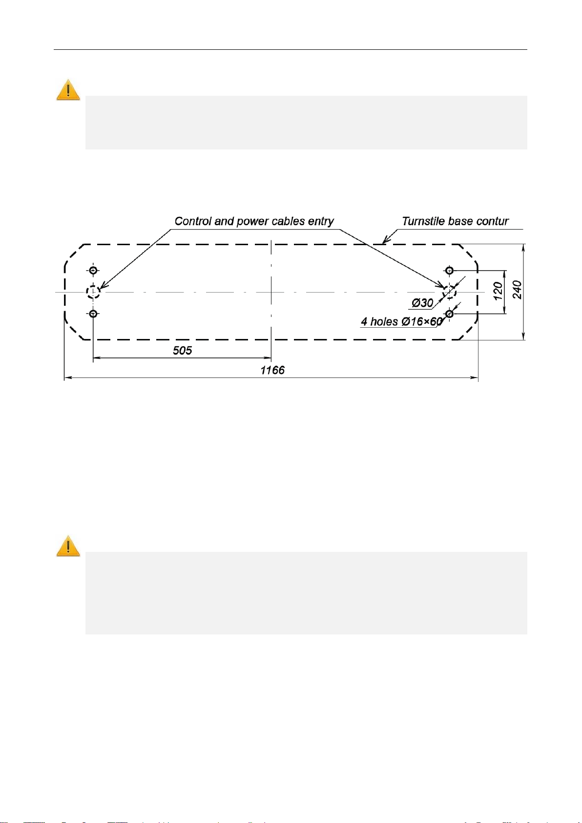
• to mark the mou nting holes acc ordin g to Fig. 14;
• to control ver tical a lignme nt of the t urnst ile with a level during ins tallatio n;
• to do installat ion of the turn stile by at leas t 2 ski lled in staller s;
• when arranging a passage area through the turnstile please take into account
that the resetting me chanism operat es as fol lows:
− at the barrier arm turning at the angle of more than 60° the reset is
effected in the direction of m ovement ;
− at the barrier arm t urning at the angle less t han 60° the reset is effect ed
counter the movement direct ion ( reset to h ome pos ition).
Note:
The angle gradient, at which the barrier arm r
operated from an ACS, it is rec ommended to arrange the p assage area in such a
way that the barrier arm s should turn in th e direct ion of mov ement at t h
Figure 11 – Installation recommen datio ns
21

Assembly & Operation Manual
By organization of the passage zone it is essential to anticipate an extra em ergency exit.
For example, “anti-panic” hinged section of PERCo-BH02 railing (ref. Section 9.4) can
serve as such an exit.
22
Figure 12 – Cable layout inside the housing
1 –CLB; 2 – indication module IM1; 3 – indication module IM2;
4 – remote connector block XS1; 5 – power cable;
6 – cable from the RC panel (W RC devic e);
7 – indication cable (3 on Fig. 13);
8 – intermediate indication cable from IM1 to IM2 (6 on Fig. 13);
9 – bracket for reader insta llation ; 10 – ACS in stal latio n zone

TTD-08A Electromechanical Box Tripod Turnstile
It is allowed to use other testing equipment and measuring tools provided
the equipment in use ensures the required parameters and measurement accuracy.
Minimum
mm
AWG 18;
HO3VV-F 2×1.5 bi-colored
AWG 13;
HO5VV-F 2×2.5 bi-colored
- Fire Alarm
outputs of CLB
3
RC-panel
40
8 triad cable
0,2
CQR CABS8 8×0,22c
4
WRC
40
5
Controller ACS
30
8.2 Installation tools
• 1.2÷1.5 kW hammer drill;
• Ø16 mm hard-alloyed drill bits;
• Floor chaser for electric raceway;
• Flat slot screwdriver No.2;
• Cross-head screwdriver;
• Horn-type and socket wrenches: S17, S13 and S10;
• Set square 90º;
• Allen key S3;
• Level;
• Measuring tape (2 m);
• Hard wire 1.5 m long for cable pulling;
• Slide caliper.
Note:
8.3 Length of cables
Cables, used for installation, are listed in table 3.
Table 3 – Cables used during the installation
Equipment connected
№
1 Power supply
2
to the turnstile
controller
- Additional equipment,
connected to inputs or
Maximum
cable
length, m
10 Twin wire 1,5
20 Twin wire 2,5
30 Twin wire 0.2
Cable type
6 triad cable 0,2 CQR CABS6 6×0,22c
cross-
section,
Example of the cable
RAMCRO SS22AF-T
2×0.22
CQR-2
23

Assembly & Operation Manual
8.4 Connection layout of the turnstile and optional equipment
Figure 13 – Connection layout of t he TTD-08A turnstil e and opt ional equipmen t
1
Elements of the scheme are listed in Table 4 Elements, marked with a star sign (*) are not
included in standard delivery set.
24
1

TTD-08A Electromechanical Box Tripod Turnstile
Legend
Name
Q-ty
A1
Control mechanism
1
A1.1
Rotation sensor unit
1
A1.2
Electromotors
1
A1.3
Electromagnet
1
A2, A3
Sidewalls with side covers assembly
2
Indication modules (on IM1 jumpers are in L position,
on IM2 – in R position)
Modules of direction indicator (on MDI1 jumper is in L position,
on MDI2 - in R position)
A4
Bracket with CLB and XS1 connector block
1
A5
Control logic board CLB.140
1
A6
RC-panel
1
A7
1
A81
ACS controller
1
A91
Turnstile power supply DC 12V
1
A101
Intrusion detector
1
A111
Siren DC12V
1
A121
Emergency opening device (Fire Alarm)
1
A13.21
A141
Remote indicator power supply
1
XS1
Remote connector block Klemsan 1/12
2
1
Cable (power of the CLB)
1
2
Control cable
1
3
Indication cable
1
4, 5
Cables of direction indicator
2
6
Intermediate indication cable
1
Wire jumper. Installed when the emergency opening devic e (A12) is
not connected, installed on default
Wire jumper. Installed when the intrusion detector (A10) is not
connected, installed on default
Table 4 – Elements of the connecti on layout
A2.1, A3.1
A2.2, A3.2
A13.11,
2
2
WRC device
1
Remote indicators 2
7
8
1
Not included in standard delivery set.
1
1
25
Assembly & Operation Manual
The manufacturer shall not be liable for any damage caused as the result of
improper installation and declines any claims arising thereof in case if the
installation is done not in compliance with the instructions provided in this
Manual.
for the access to the barrier arms rotation unit, of those cables that are
ing the cables in the electric raceway and inside the
turnstile housing. Be careful and prevent the turnstile from falling before it is
fixed.
8.5 Installation pr oc edure
Attention!
Content of installation procedures is presented per f eedback in sec 8.1. Equipments and
tools, required for installation, are listed in sec. 8.2. Cable types, used during installati on,
are listed in sec. 8.3. Connection layouts of the turnstile and optional equipment are
presented in sec. 8.4. Item numbers are listed in accordance to Fig. 2.
Figure 14 – TTD-08A turnstile housing i nstallat ion la yout
During turnstile installation keep to the following procedure:
1. Unpack the turnstile and check the completeness as per Section 4 of the product
certificate.
2. Install the turnstile power supply unit in its place (See power supply unit certificate
for installation procedure of the power supply unit).
3. Drill the holes for anchor bolt sleeves to fix the turnstile housing (Ref. Fig. 14.
4. If you lay the cables under the floor surface, prepare the electric raceway to the
cables laying zone of the turnstile housing. The cables layout inside the turnstile
housing is shown in Fig. 12.
Caution!
• I t is necessary to leave a reserve of length, enough for hinged j oint removal and
connected to the remote connector block and control board.
• Fix the housing after lay
1. Insert the sleeves for the anchor bolts into the holes so that they do not stick out
above the floor surface.
2. Remove the turnstile housing top cover (3) (Ref. Section 6.
5. Remove the turnstile housing side cov er (7), as sembled with a top cover (9). For
this purpose:
• Loos en t wo screws (2 in Fig. 15).
• Remove the wall from the housing and disconnect the cable, connecting
26
indication plates (8 on Fig. 12) from indication plate 2, located under the cover.
• Rem ov e t he bac k panel and acc urately put it on the straight stable surface.

TTD-08A Electromechanical Box Tripod Turnstile
card reader’s installation is anticipated in the turnstile
housing. With installation of third manufacturers readers they should correspond
sensors read range ............................................................. not less than 50 mm
6. Remove the turnstile housing side cover (6), assembled with a top cover (8). In
order to do that:
• Loos en t wo screws (1 in Fig. 15).
• Tak e a side cover aside and detach a cable (8 in Fig. 12), connecting indication
blocks, from indication block IM1 (located under a top cover), and an in dication
cable (7 in Fig. 12), from control block.
• Rem ov e a side cov er and ac curately put it on the straight stable surface.
3. Set up the housing on anchor bolt sleeves and f ix it with the M10 bolts through
the holes in the post base.
4. Connect the power c able ( 13) to a connector block XS1 (Ref. Fig. 13).
5. Connect the c able of the RC panel ( 12) to a connector block XS1.
Figure 15 – Layout of bracket cap-screws
7. If needed, connect cables from other devices to corresponding connector blocks of
control board.
8. If needed, inst all the board of outer controller ACS inside the turnstile housing on
the bracket (10 in Fig. 12); to do this, use clips with self adhesive foundat ions FSS5 from the delivery set.
6. If needed, inst all card readers on, specially provided for it, brackets on the housing
flanks (9 in Fig. 12). To ease the installation procedure, remove the bracket by
loosening two nuts M3 with an open end wrench S5,5, located below under the
bracket. To connect card readers use free contacts (15 - 24) of the remote
connector block XS1.
Attention!
Possibility of PERCo
with following technical characteristics:
overall readers dimensions ................................... not more than 135×90×30 mm
7. Check serviceability and accuracy of all the electrical connections.
8. Fix all ca bles with the help of self adhesive foundations and fixed brace rods from
the delivery set.
9. Put back si de panels (6, 7), assembled with top covers (8, 9) in an order , opposite
to removal.
10. Put back a top cover (3) in an order, opposite to removal.
11. Run a test switch on of the turnstile as specified in Clause 9.1.
12. Check the work of the turnstile with RC panel, according to section 9.2 or 9.3
depending on a switched control mode.
After installation and testing have been completed, the turnstile is ready for operation.
27

Assembly & Operation Manual
ea any objects with dimensions
Do not jerk and hit any elements of the turnstile so as to prevent their
damage or corrosion of the surf aces.
level signal supply to
connector block
relatively to the co ntact “GND”.
9 OPERATION INSTRUCTIONS
When operation the equipm ent, obs erve pr ecautio ns (Cla use 7.2).
Warning!
• Do not move through the turnstile passage ar
exceeding t he width of the passa geway.
•
mechanical deformation.
• Do not dismant le or adjust mec hanism s ensuri ng operat ion of t he turns tile.
• Do not use substances for cl eaning of the turnst ile th at may ca use mechan ical
9.1 Power-up
Follow these steps:
1. Ch eck acc uracy of all the c onnect ions.
2. M ake sure the upper barrier arm is in emergency position (passage are a is free) .
3. Connect the turnstile power supply unit to the AC outlet with the voltage and
frequency rating according to the certificate for the power supply unit. Red
indicators (ban on passa ge) will light up on t he indication mod ules, on the RC pa nel
the red indicator above “A lways locked” will li ght up.
4. M anually lift up th e foldi ng arm. Th e arm wi ll be fix ed in th is posit ion.
5. Check operation of the intrusion detector and siren (if included in the delivery set
and installed accordingly). After the power-up wait until the moment of the test
indicator (inside the i ntrusion detector) going of f (from 10 to 50 sec). Put your hand
before the intrusion detector. The continuous signal will sound when the intrusion
detector activates. To e liminate that sound sig nal press an y button on the RC panel.
The sound will stop without pres sing the button in 5 sec.
The turnstile is ready for op erati on.
9.2 Operating modes of the turnstile at pulse control mode
See Table 5 for the operating m odes set from the RC panel and for the corresponding
indication. Setting the operating modes for each direction is independent, i.e. setting
the operating mode for one direction does not change the operating mode set earlier
for the opposite one.
Note:
Pressing the button on the RC pane l corresponds t o the lowthe contacts (“Unlock A”, “Unlock B” and “Stop”) of the XS1
The RC panel overall view is given in Fig. 4. Herewith:
• The “Single passage in the set direction” mode can be changed to the “Always
free” mode for the same direction, or to the “Always locked” mode.
• The “Free passage in the set direction” mode can be changed to the “Always
locked” mode only.
• In the “Single passage in the set direction” mode the turnstile will close
automatically aft er a person’s passage in t he set direction. The tur nstile will also
close automatically, if t he passa ge is not m ade wit hin 5 se c.
• In the “Bi-directional single passage” mode after the passage in one direction the
countdown of the passage waiting time (5 sec.) for the opposite direction is
recommenced.
28

TTD-08A Electromechanical Box Tripod Turnstile
modes
Indication
The red
button is on
The “Red
direction are on
Single passage
direction)
The “Green
direction.
simultaneously
direction)
After the passage in
direction
Press all the 3
RIGHT
Table 5 – Pulse control mode (the jumper is set on the J1 connector)
The turnstile
operating
Always locked
(Locked for
entry and exit)
in the set
direction (open
for passage of
one person in
the chosen
Bi-directional
single passage
(open in both
directions for
‘one-by-one’
passage)
Actions
to do
Press the STOP
button on the RC
panel
Press the LEFT/
RIGHT button on
the RC panel
Press both the LEFT
and RIGHT buttons
on the RC panel
simultaneously
On the RC
panel
indicator above
the STOP
The green
indicator above
the button of the
chosen passage
direction «Left»/
«Right» is on
The two green
indicators
(«Left» and
«Right») are on
On the
turnstile
crosses” for
each passage
The “Green
arrow” in the
chosen
passage
direction is on
arrow” for each
passage
direction is on.
After the
passage in the
chosen
direction the
“Red cross” is
on for that
Turnstile status
The turnstile is locked
When the passage is
completed, the
turnstile is locked
The turnstile is locked
in the direction of
completed passage
Free passage in
the set direction
(open for free
passage in the
chosen
direction)
Free passage in
the set direction
and single
passage in the
opposite
direction (open
for free passage
in the chosen
direction and for
passage of one
person in the
opposite
Always free
(open for entry
and exit)
Press the STOP
button and the button
corresponding to the
chosen passage
direction LEFT/
RIGHT
Set the “Free
passage in the set
direction” mode for
one direction and
“Single passage in
the set direction” for
the other.
buttons on the RC
panel
simultaneously:
LEFT, STOP and
The green
indicator above
the button of the
chosen passage
direction «Left»/
«Right» is on
The two green
indicators
(«Left» and
«Right») are on.
The two green
indicators
(«Left» and
«Right») are on
The “Green
arrow” in the
chosen
passage
direction is on.
The “Green
arrows” for
each passage
direction are on.
After the single
passage the
“Red cross” is
on.
The “Green
arrows” for
each passage
direction are on.
Turnstile remains
open in the set
direction
the free passage
direction the turnstile
remains open in both
directions. After the
passage in the single
passage direction the
turnstile remains
open in the free
passage direction but
it gets locked in the
single passage
The turnstile remains
open
29

Assembly & Operation Manual
contacts of the output relay are broken or the output transistor is
contacts of the output relay are closed or the output transistor is
open.
Indication
On the
turnstile
Both passage
entry and exit)
The high level —
on the contact “Stop”
One of the
direction)
and exit)
The low level —
on the contact “Stop”
9.3 Operating modes of the turnstile at potential control mode
See Table 6 for the operating modes set from the RC panel. Sett ing the operating modes
for each direction is independent, i.e. setting the op erat ing mode for one dir ection does not
change the operating mode set earlier for the opposite one.
If by the moment of passage through the turnst ile the low level is present on the contact,
corresponding to the set passage direction, the turnstile remains open in the set direction.
For the ACS outputs not e the following:
• High level —
closed.
• Low level —
Table 6 – Potential control mode (the jumper is taken off from the J1 connector)
The turnstile
operating
modes
directions are
locked (the
turnstile is
locked both for
passage
directions is
open (the
turnstile is open
for passage in
the set
Both passage
directions are
open (the
turnstile is open
both for entry
Actions
to do
on contacts
“Unlock A”
and “Unlock B”
or low level —
The low level —
on the contact
corresponding
to the passage
direction, the high
levels — on the other
contacts
on contacts
“Unlock A”
and “Unlock B”.
The high level —
On the RC panel
The red indicator
above the STOP
button is on
The green
indicator above
the button of the
chosen passage
direction “Left” /
“Right” is on
The two green
indicators
(“Left” and
“Right”) are on
The “Red
crosses” for
each passage
direction are
on
The “Green
arrow” in the
chosen
passage
direction is on
The “Green
arrows” for
each passage
direction are
on
Turnstile status
The turnstile is locked
When the passage
is completed, the
turnstile is locked
The turnstile remains
open
9.4 Actions in emergency
For urgent evacuation of people from business facilities in cas e of fire, natural calamities
and other emergencies, the additional emergency exit should be provided. Such
emergency exit can be the automatic anti-panic rotary section BH-02.
The additional emergency exit can be provided by the turnstile passage ar ea. Const ruction
of the turnstile enables immediate clear of passage way without use of any special keys or
tools. By putting the Fire Alarm signal to turnstile logic board the barrier arm automatical ly
falls down allowing the free exit.
The arm also drops down automatically at a power supply loss.
30

TTD-08A Electromechanical Box Tripod Turnstile
Fault
Possible cause
Remedy
At the power-up the
RC panel
The turnstile is not
the RC panel
9.5 Troubleshooting
Possible faults, which can be cleared by the users themselves, are listed in Table 7.
Table 7 – Possible faults and remedy
turnstile doesn’t work,
and there is no light
indication on the
turnstile housing and the
controlled in one of the
directions, and there is
light indication on the
turnstile housing and on
No supply voltage
to the CLB
The CLB does not
receive a control
signal for this
direction
Switch off the turnstile power supply from the AC
mains, open the turnstile housing cover. Check the
power cable serviceability and reliability of its
connection to the CLB XS1 and XT3 connector
blocks
Switch off the turnstile power supply from the AC
mains, open the turnstile housing cover, and remove
the outer panel. Check the RC panel / WRC kit / ACS
controller cable serviceability and reliability of its
connection to the CLB XS1 connector block
In case of other faults and defects, please apply to the PERCo Technical Support
Department (the PERCo TSD).
31

Assembly & Operation Manual
Avoid ingress of lubricant on th e rotati on sensor disc an d the r oller sur faces.
10 MAINTENANCE
The turnstile maintenance is required once a year and in case of any technical failures
the turnstile must be ser viced immediate ly after repair w orks. The maint enance should
be carried out by qualified mechanic only after careful study of this Manual.
To do maintenance proceed as follows:
1. Disconnect the turnstile power supply from the AC mains, the folding arms will
automatically fall dow n.
2. Remove the turnstile top cover (3) from the turnstile housing as described in
Section 6. Lay the cover on a flat s teady s urface.
3. To access the rotation unit of turnstile barrier arms, take off the bracket with control
board and remote connector block. For this purpose: unscrew 6 screws (3 on
Fig. 15), which fix the bracket on the turnstile housing and accurately t ake a bracket
aside without damaging connected cables.
4. Inspect the resetting mechanism (a pusher, springs and a roller), optic sensors
and a damper (Ref. Fig. 16).
5. Remove dust from a rotation sensor disc, located in the spacing of the rotation
optic sensors, with al cohol-gasoline blend appl ied with a cloth. Avoid ingres s of
dust into the operational s pacin g of the o ptic sen sors.
Figure 16 – Interior components of the turnstile mec hanism
6. Lubricate with machine oil (lubrication poi nts are m arked in F ig. 16):
• four bushes of the resetting mechanism (two – on t he rotation axis of the
pusher;
• two – on the faste ning axis of the sprin gs as well as holes in the fastening
parts of the springs); 2-3 drops of oil in each lubrication po int.
Attention!
32

TTD-08A Electromechanical Box Tripod Turnstile
7. Fix the bracket with control board and remote connector block in an order, opposite
to removal.
8. Check reliability of the cable connections to the CLB connector blocks and if
necessary tighten the cab le fixin g screw s.
9. Check reliability of the barrier arm (5) fastening.
10. Remove side panels (6, 7), assembled with top covers (8, 9) in an order (ref.
Section 8.5. Check reliability of the turnstile housing faste ning to the floor and if
necessary, tighten the anch or bolt s.
11. Put back side panels (6, 7), assembled with top covers (8, 9) in an order, op posite
to removal.
12. Return the top cov er (3) into its op erating positio n.
13. Energize the turnst ile and l ift up the foldi ng arm.
14. Check operation of t he turnst ile in accord ance wit h Sect ion 9 of this Manual.
After maintenance works ar e compl ete the turnsti le is rea dy for f urther op erati on.
In case of any defects revealed during visual check please apply to the PERCo
Technical Support Departm ent (the PERCo T SD).
11 TRANSPORTATION AND STORAGE
The turnstile in the origi nal package should be transported in closed freight containers
or other closed type cargo t ranspor t units.
During storage and transportation the boxes with the turnstiles can be stacked
maximum 2 layers high.
Storage of the turnstile is allowed in dry indoor facilities at an ambient air temperature
from –40°C to +55°C at relati ve air humidit y 98% at +25°C.
After transportation or storage at temperatures bel ow zero or at high air h umidity, prior
to installation the turnstile must be kept in the original package for no less than
24 hours indoors under conditions corresponding to operation conditions
(Ref. Section 2).
33

Assembly & Operation Manual
high level — the relevant button on the RC panel has not been pressed.
APPENDIXES
Appendix 1. Control signal algorithm at pulse control mode
Note:
For the RC panel:
• ac t ive front — pressing of the relevant button on the RC panel;
• lo w level— the relevant button on the RC panel has been pressed;
•
The command is a signal active front (signal transfer from t he high level to the low leve l) at
any of the contacts at presence of the corresponding signal levels at the other contacts.
The following commands can be formed by sending a low-level signal to the contacts
“Unlock A”, “Stop” and “Unlock B” of the XT1.L (or XS1) connector block relatively to the
contact “GND”:
Always locked (locked for entry and exit)
Active front is at the contact “Stop” while there is a high level at the contacts “Unloc k A”
and “Unlock B”. Both passage directions are locked at this command.
Single passage in the direction A (open for passage of one person
in the direction A)
Active front is at the contact “Unlock A” while there is a high level at the contacts “Stop”
and “Unlock B”.
At this command the passage direction A opens either for 5 sec. or until the pas sage has
been made in this direction or until the command «Always locked», and the status of the
passage direction B does not change at that. The command is ignored if
at the moment of its receipt the status of the passage direction A is «Always free».
Single passage in the direction B (open for passage of one person
in the direction B)
Active front is at the contact “Unlock B” while there is a high level at the contacts “Stop”
and “Unlock A”.
At this command the passage direction B opens either for 5 sec. or until the pas sage has
been effected in this direction or until the command «Always lock ed», and the st atus of the
passage direction A does not change. The command is ignored if at the moment of its
receipt the status of passage direction B is «Always free».
Bi-directional single passage (open in both directions for ‘one-by-one’ passage)
Active front is at the contact “Unlock A” while there is a low level at the contact “Unloc k B”
and a high level at the contact “Stop”,
or active front is at the contact “Unlock B” while there is a low level at the contact
“Unlock A” and a high level at the contact “Stop”.
At this command the both passage directions open either for 5 sec. each or until the
passage has been effected in the given direction or until the command «Alwa ys locked»
is received. The command is ignored for the passage direction, which status at the
moment of its receipt is «Always free».
Free passage in the direction A (open for free passage in the direction A)
Active front is at the contact “Unlock A” while there is a low level at the contact “Stop” and
a high level at the contact “Unlock B”,
or active front is at the contact “Stop” while t here is a l ow level at the contact “Unloc k A”
and a high level at the contact “Unlock B”.
34

TTD-08A Electromechanical Box Tripod Turnstile
is closed.
At this command the passage direction A opens until the command «Always locked» is
received; the status of the passage direction B does not change at that.
Free passage in the direction B (open for free passage in the direction B)
Active front is at the contact “Unlock B” while there is a low level at the contact “Stop” and
a high level at the contact “Unlock A”,
or active front is at the contact “Stop” while t here is a l ow level at the contact “Unlock B”
and a high level at contact “Unlock A”.
At this command the passage direction B opens until the command «Always locked» is
received; the status of the passage direction A does not change at that.
Free passage (open for free passage in both directions)
Active front is at the contact “Unlock A” while there is a low level at the contacts
“Unlock B” and “Stop”,
or active front is at the contact “Unlock B” while there is a low level at the contacts
“Unlock A” and “Stop”,
or active front is at the contact “Stop” while there is a low level at the cont acts “Unlock
A” and “Unlock B”.
The both directions open at this command until the command «Always locked» is
received.
Appendix 2. Control signal algorithm at potential control mode
Note:
For an ACS controller outputs:
• lo w level – either contacts of the output r elay are closed or the output transistor
is open.
• h igh level – either contacts of the output relay are broken or the output transistor
Both directions are locked (locked for entry and exit)
There is a high level at the contacts “Unlock A” and “Unlock B”,
or a low level at the contact “Stop”.
Both passage directions close at this command..
The direction A is open (open for passage in the direction A)
There is a low level at the contact “Unlock A” while a high level is present at the contacts
“Stop” and “Unlock B”.
At this command the direction A opens up to the low-level signal removal from the contact
A or until the com mand «Both directions locked» is received. The st atus of the direction B
does not change at that
The direction B is open (open for passage in the direction B)
There is a low level at the contact “Unlock B” while there is a high level at the contacts
“Stop” and “Unlock A”.
At this command the direction B opens up to the low-level signal removal from the contact
B or until the command «Both directions locked» is received. The st atus of the direction A
does not change at that.
Both directions are open (open for entry and exit) -
There is a low level at the contacts “Unlock A” and “Unlock B” while t here is a high level at
the contact “Stop”.
Both directions open at this command up to the low-level signal removal from one of the
contacts A (B) or until the command «Both directions closed» is received.
35

PERCo
P.O. Box 87,
Saint Petersburg, 1942 95,
Russia
Tel: +7 812 321 61 72
Fax: +7 812 292 36 08
E-mail: export@perco.ru
support@perco.ru
www.perco.com
 Loading...