


ASSEMBLY AND OPERATION MANUAL
WARRANTY CARD
RTC-15.3
Protective Capony

Protective Canopy
RTC-15.3
Assembly and Operation Manual
Warranty Card

CONTENT:
1 APPLICATION......................................................................................................................... 3
2 OPERATION CONDITIONS.................................................................................................... 3
3 TECHNICAL SPECIFICATIONS ............................................................................................. 3
4 DELIVERY SET....................................................................................................................... 4
4.1 Standard delivery set......................................................................................................... 4
4.2 Optional equipment supplied on request........................................................................... 4
5 DESIGN...................................................................................................................................
4
5.1 Main features..................................................................................................................... 4
5.2 The canopy design............................................................................................................ 4
6 SAFETY REQUIREMENTS.....................................................................................................6
6.1 Installation safety requirements......................................................................................... 6
6.2 Operational safety requirements....................................................................................... 6
7 INSTALLATION WORK........................................................................................................... 7
7.1 General recommendations................................................................................................ 7
7.2 Installation tools................................................................................................................. 7
7.3 Canopy installation............................................................................................................ 7
8 TRANSPORTATION AND STORAGE .................................................................................. 10
9 WARRANTY PERCo.............................................................................................................11

RTC-15.3 Protective Canopy
Dear customers!
We thank You for choosing the turnstile manufactured by PERCo.
You have purchased a high quality product, which will be long lasting
in operation provided that installation and operation rules are observed.
The Operation Manual (the Manual) of the RTC-15.3 Protective canopy for the RTD-15 Full
height rotor turnstile contains data on transportation, storage, installation, operation,
maintenance and warranty of the product. The installation should be undertaken in strict
accordance with this Manual.
1 APPLICATION
The RTC-15.3 Protective canopy (the canopy) is designed for use together with the
RTD-15 Full height rotor turnstile (the turnstile) as protection of the turnstile against direct exposure
to the elements.
Warning!
The RTC-15.3 canopy is compatible only with the RTD-15 turnstiles with serial numbers
67хххххх and is not compatible with the RTD-15 turnstiles with serial numbers 46хххххх!
2 OPERATION CONDITIONS
The canopy, in accordance with the resistance to environmental exposure, complies with
GOST 15150-69, Category N1 (outdoor operation).
Operation of the canopy is allowed at ambient temperature from -40°C to +40°C and relative air
humidity of up to 98% at +25°C.
3 TECHNICAL SPECIFICATIONS
Overall dimensions (H × W × D) .................................................................... 2379×1807×2594 mm
Weight (net) ...................................................................................................................... max 70 kg
Mean lifetime ............................................................................................................................. min 8
Figure 1. Overall canopy dimensions (frontal view)
3

Assembly and Operation Manual
4 DELIVERY SET
4.1 Standard delivery set
Primary parts:
Canopy’s half-frame #1............................................................................................................ 1
Canopy’s half-frame #2............................................................................................................ 1
Post ......................................................................................................................................... 4
Jointing plate ........................................................................................................................... 1
Fasteners:
Hex socket screw M6×20 ......................................................................................................21
Hex socket screw M8×30 ....................................................................................................... 8
Washer 6 ...............................................................................................................................16
Washer 8 ................................................................................................................................ 8
Spring washer 6 .................................................................................................................... 21
Spring washer 8 ...................................................................................................................... 8
Self-tapping screw 4.2×16 .......................................................................................................4
Plug Ø16 ................................................................................................................................. 5
In-line documentation:
Assembly & operation manual with warranty card .................................................................. 1
Package:
Package box ........................................................................................................................... 3
4.2 Optional equipment supplied on request
Metal anchor with bolt M10×60 PFG IR 10-15 («SORMAT», Finland) ..................................16
5 DESIGN
5.1 Main features
High corrosion resistance of the aluminium frame ensures long period of service even in
unfavourable environments/
Low weight makes the installation easier/
High durability polymeric powder keeps the outward appearance essentially unchanged for
many years of service.
5.2 The canopy design
The design is shown in Fig. 2. Numbers of the position correspond to Fig.2.
The canopy consists:
two half-frame (1) and (2) with transparent infill and the sloping drain;
four posts (3);
jointing plate (6).
The half-frames (1) and (2), and the posts (3) with bottom flanges (4) for fixing the posts to the
mounting surface and top flanges (5) for fixing the posts to the half-frames assembly, are made of
high durability aluminum profile.
The canopy posts are to be fixed to the foundation surface with anchor bolts M10 through
mounting holes in supporting flanges.
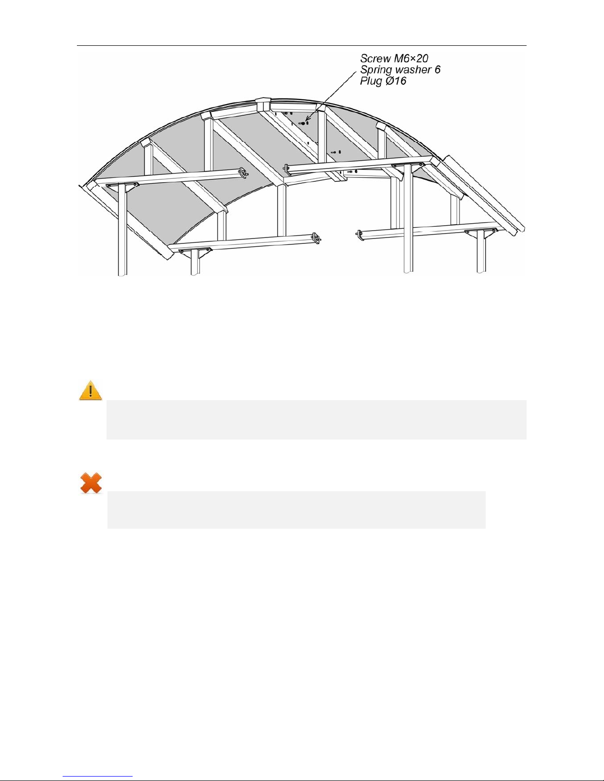
Each canopy’s half-frame shall be fixed: to two posts with screws M6×20 and to the side part of the
turnstile top channel with screws M8×30 (see Figure 2).
The canopy’s half-frame shall be
connected in their upper part with screws M6×20 (see Figure 3).
The joint
line between the half-frames is covered by a jointing plate (6) and fix by four self-tapping
screws 4.2×16.
Each half-frame has a sloping drain (7) for drainage.
4

RTC-15.3 Protective Canopy
Figure 2. The canopy design:
1 and 2– half-frames; 3 – post; 4 – bottom flange; 5 – top flange;
6 – jointing plate; 7 – drain
5
Assembly and Operation Manual
Figure 3. Mounting half-frames among themselves
6 SAFETY REQUIREMENTS
6.1 Installation safety requirements
Installation of the canopy should be carried out by qualified personnel only, in strict accordance
with this Manual and general requirements for installation work.
Warning! While doing the installation work:
use only serviceable tools;
be particularly careful when installing parts of the canopy before they are secured in
place, prevent the parts from fall.
6.2 Operational safety requirements
Do not:
use the canopy if it is not fixed to the turnstile.
make mechanical shock and jerking of the canopy.
use substances and tools that may cause damage to the surface of the canopy.
Make sure that snow that may cover the canopy in winters is not higher than 200 mm.
6

RTC-15.3 Protective Canopy
7 INSTALLATION WORK
7.1 General recommendations
Warning!
The manufacturer will not accept liability for any damage to the canopy
or other equipment, or otherwise loss caused as a result of improper installation, and will
dismiss any claims by the customer should the installation work be carried out not in
accordance with this Manual.
Installation is an operation substantially responsible for durability and serviceable life of the
canopy. Study this section carefully before commencing the installation work, and strictly follow the
instructions.
We advise:
installation to be carried by at least two persons in assembly and installation work;
mounting the canopy on flat, solid concrete floors (grade 400 or higher), stone or similar
foundations at least 150 mm thick;
using reinforcing elements 500×500×500 mm for weaker foundations;
using mounting hardware as recommended in sect. 4.2.
7.2 Installation tools
Use the following tools for the installation work:
1.21.5 kW electric perforator;
0.6 kW electric drill;
Ø16 mm carbide drill bits;
Ø3.5 drill bits;
SW5; SW6 hex-nut wrenches;
PH2 cross-tip screwdriver, 150 mm;
pair of trammels;
3 m tape-measure;
level gauge;
two stepladders (four steps or more).
Note:
Use of other similar tools is allowed as long as it does not reduce quality of the installation
work.
7.3 Canopy installation
Recommendations how to prepare mounting holes in the foundation (the mounting surface) are
given with regard to anchor bolts for solid concrete floors or similar foundations (see sect. 7.1). Use
relevant mo
unting hardware for installation on different foundations.
1. Unpack the canopy, check completeness of the delivery set according to sect. 4.1.
2.
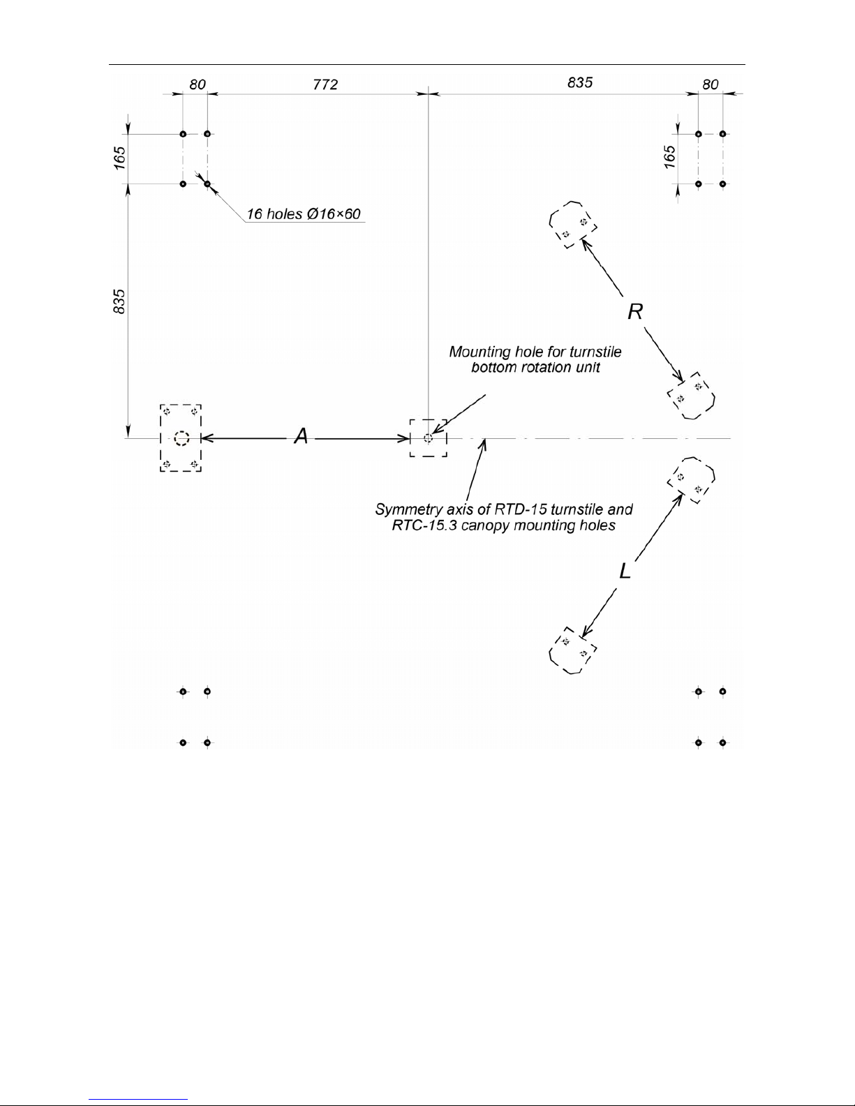
Mark out the mounting holes for installation of the posts
(3) according to Fig. 4. Carry out the
marking together with that for turnstile mounting holes given
in the Operational Manual to the RTD-15 Full Height Rotor Turnstile. Symmetry axis of
turnstile and canopy mounting holes geometrically coincide (Figure 4).
3.
Prepare holes for the anchor bolts.
7
Assembly and Operation Manual
Figure 4. Hole pattern for mounting of the canopy posts (3) relative to the turnstile mounting
holes:
A – mounting point of the turnstile barrier section.
L – mounting point of the turnstile left guide barrier section.
R – mounting point of the turnstile right guide barrier section.
Figure 4 shows a sketch layout of the turnstile mounting holes. Exact coordinates of the holes in A,
L and R mounting points are given in the Operational Manual to the RTD-15 Full Height Rotor
Turnstile.
8
RTC-15.3 Protective Canopy
4.
Set the anchors all the way down the prepared holes.
Warning!
Further work should be carried out after installation of the RTD-15 turnstile.
Be particularly careful when installing parts of the canopy before they are secured in
place, prevent the parts from fall.
5. Erect and fix the posts with anchor bolts observing their verticality by means of a level gauge,
use insertions when necessary.
6. Remove the plugs from the side surfaces of the turnstile top channel (4 plugs on each side of
the channel).
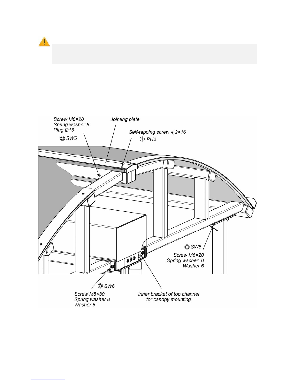
7. Install the first canopy half-frame on the upper flanges of the posts from one side of RTD-15
turnstile, matching fixation holes with the holes in the posts. Fix the canopy half-frame with
screws M6×20 with washers to each stand, wrench SW5 (see Figure 5).
Figure 5. Juncture of the canopy to the turnstile top channel
8. Fix canopy half-frame with four bolts M8×30 to the turnstile top channel, wrench SW6 (see
Figure 5). Tightening of bolts is preliminary. It is recommended to seal the joint of flange and
top channel
with atmospheric silicon sealer before fixing of the bolts.
9. Similarly, carry out the installation of the second half-frame of the canopy on the other side of
the turnstile. Tightening of bolts is preliminary.
9

Assembly and Operation Manual
10.
Connect the half-frames in the zone of the upper power tube with bolts M6×20 – 5 pcs.
(wrench SW5) to obtain a sturdy construction. Use plugs for the bolt holes.
11. Check all threaded connections of the canopy frame and tighten them.
12. Set the jointing plate into working position, fixing it with 4,2×16 self-tapping screws (4 pcs.),
having preliminary drilled the holes by drill Ø3,5 (see Figure 6).
Figure 6 The top view of the connected half-frames #1 and #2
with the installed jointing plate
The canopy is installed. Consult with PERCo Technical Support Department when necessary.
8 TRANSPORTATION AND STORAGE
The canopy in the standard delivery set (Section 4) is packed in three transport boxes, which
protect its components from damage during transportation and storage.
Table 1 Overall dimensions and boxes contents
№
Dimensions
(Length × width × height)
Contents
Weight (gross),
not more than
1 191×126×57
Canopy’s half-frame #1 assembled - 1 pcs.
Jointing plate - 1 pcs.
Fasteners – 1 kit
45
2 191×126×57 Canopy’s half-frame #2 assembled - 1 pcs. 44
3 223×53×31 Posts – 4 pcs. 21
The canopy in the original package should be transported only in closed freight containers or other
closed type cargo transport.
During storage and transportation the boxes can be stacked no more than 2 layers high.
10

RTC-15.3 Protective Canopy
The canopy should be
stored indoors at ambient temperatures between -40°C to +55°C and
relative air humidity no more than 98% at + 25°C. The storage facilities should be free from acid
and alkali vapours, or corrosive gases.
If prior to installation the canopy was transported or stored at below-zero temperatures or high air
humidity, it should be kept in package for no less than 24 hours under operation conditions given in
sect.2.
9 WARRANTY PERCo
PERCo (the Manufacturer) warrants that the RTC-15.3 Protective Canopy for RTD-15 Full
Height Rotor Turnstile (the Product) complies with applicable statutory safety requirements,
electromagnetic compatibility provided that the instructions on storage, installation and operation,
given in the Assembly & Operation Manual, are observed.
The warranty period is 5 (five) years commencing from the date of sale.
Should there be no date of sale on the warranty card, the warranty period shall commence from
the date of manufacture specified in the Certificate and on the Product label.
In the post-warranty period the replacement parts/components are warranted to be free from
defects in material or workmanship for a period of 3 (three) months from the date of shipment of
the repaired/replaced Product to the Customer.
All claims with regard to quantity, completeness and defects to appearance of the Product
delivered are accepted by the Manufacturer in writing within no more than 5 (five) working days
after the products are received by the Customer. In case of failure to meet the abovementioned
deadline no claims are accepted.
The Warranty does not cover:
products, parts and components with:
- external mechanical damages resulting in the Product’s fault;
- defects resulting from Customer's improper testing, operation, installation, maintenance,
modification, alteration, or adjustment;
- damages due to force majeure circumstances (natural disasters, vandalism etc.) or
defects as a result of external circumstances (power surges, electric discharge, etc);
fuses, accumulators, galvanic elements and other components, replacement of which is
performed by the Customer in accordance with the Product’s in-line documentation.
To the maximum extent permitted by the acting law, the Manufacturer does not incur a liability for
any direct or indirect losses of the Customer, including but not limited to loss of profit or data,
losses caused by idle period, missed profit, and etc related to use or impossibility to use products
and software, including possible software errors and failures.
Within the warranty period the products are repaired free of charge at the Manufacturer’s site. The
Manufacturer reserves the right to repair failed product or replace it with an operational one. Time
of repair is specified at the moment the Product is accepted for repair. Transportation cost to and
back from the place of repair shall be borne by the Customer.
In order to shorten the repair time the Customer must inform the Manufacturer’s Technical Support
Department (the TSD) of the problem with the Product’s operation and/or about the origin of the
fault by submitting a filled-in Technical Support Form by e-mail, fax or via the Manufacturer’s
website or communicate directly a specialist of the TSD.
The Manufacturer reserves the right not to accept the Product for repair from the Customer who
failed to submit the Technical Support Form.
The Manufacturer’s warranty obligations don’t cover attendance by the experts
of a Customer and maintenance of any Product on site
If in the course of the examination taken by the Manufacturer of the Product or its
parts/components believed to be faulty, no faults have been detected, the Customer is responsible
for compensation of the Manufacturer’s expenses related to the examination.
11

Assembly and Operation Manual
Apart from the warra
nties mentioned above the Manufacturer does not provide any other
warranties with regard to compatibility of a Product purchased with software or products produced
by other manufacturers as well as any warranties that this Product will fit for the purposes not
stipulated in the Product’s in-line documentation.
The warranty does not provide for any claims with regard to the technical specifications of the
Product in case they are in compliance with those stated by the Manufacturer. The Manufacturer
does not guarantee that the Product purchased will meet Customer’s requirements and
expectations.
PLEASE NOTE THAT PERCo PRODUCES TECHNICALLY
SOPHISTICATED PRODUCTS THAT, IF NOT FAULTY,
CANNOT BE RETURNED BACK IF BY SOME REASON
THE CUSTOMER DEEMS THEM UNSATISFACTORY
The PERCo RTC-15.3 Protective Canopy is in conformity with the essential
requirements of the EU’s Machinery, Low-Voltage and EMC Directives and carries
the CE marking accordingly.
12

WARRANTY CARD
RTC-15.3 Protective Canopy
for RTD-15 Full Height Rotor Turnstile
Date of manufacture: ____________________ 201___
Quality Control Seal
_____________________________________________________________
Date of sale: « » ____________________ 201___
____________________________________
(signature, seal)
Cutting line
WARRANTY REPAIR COUPON
RTC-15.3 Protective Canopy
for RTD-15 Full Height Rotor Turnstile
Date of manufacture: ____________________ 201___
Quality Control Seal
_____________________________________________________________
Date of sale: « » ____________________ 201___
____________________________________
(signature, seal)


PERCo
Polytechnicheskaya str., 6A,
194021, Saint Petersburg
Russia
Tel: +7 812 247 04 64
E-mail: export@perco.com
support@perco.com
www.perco.com

www.perco.com
 Loading...