

Page 1
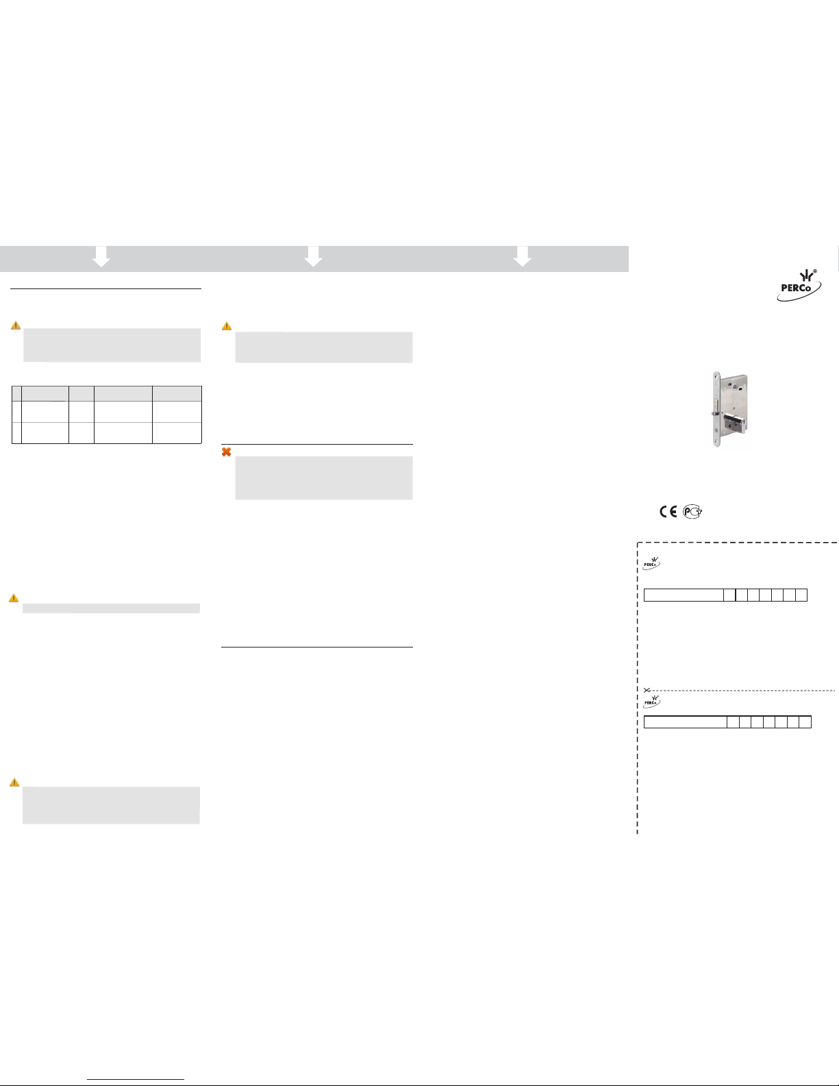
WARRANTY CARD
WARRANTY REPAIR COUPON
Cutting line
Cutting line
1. APPLICATION
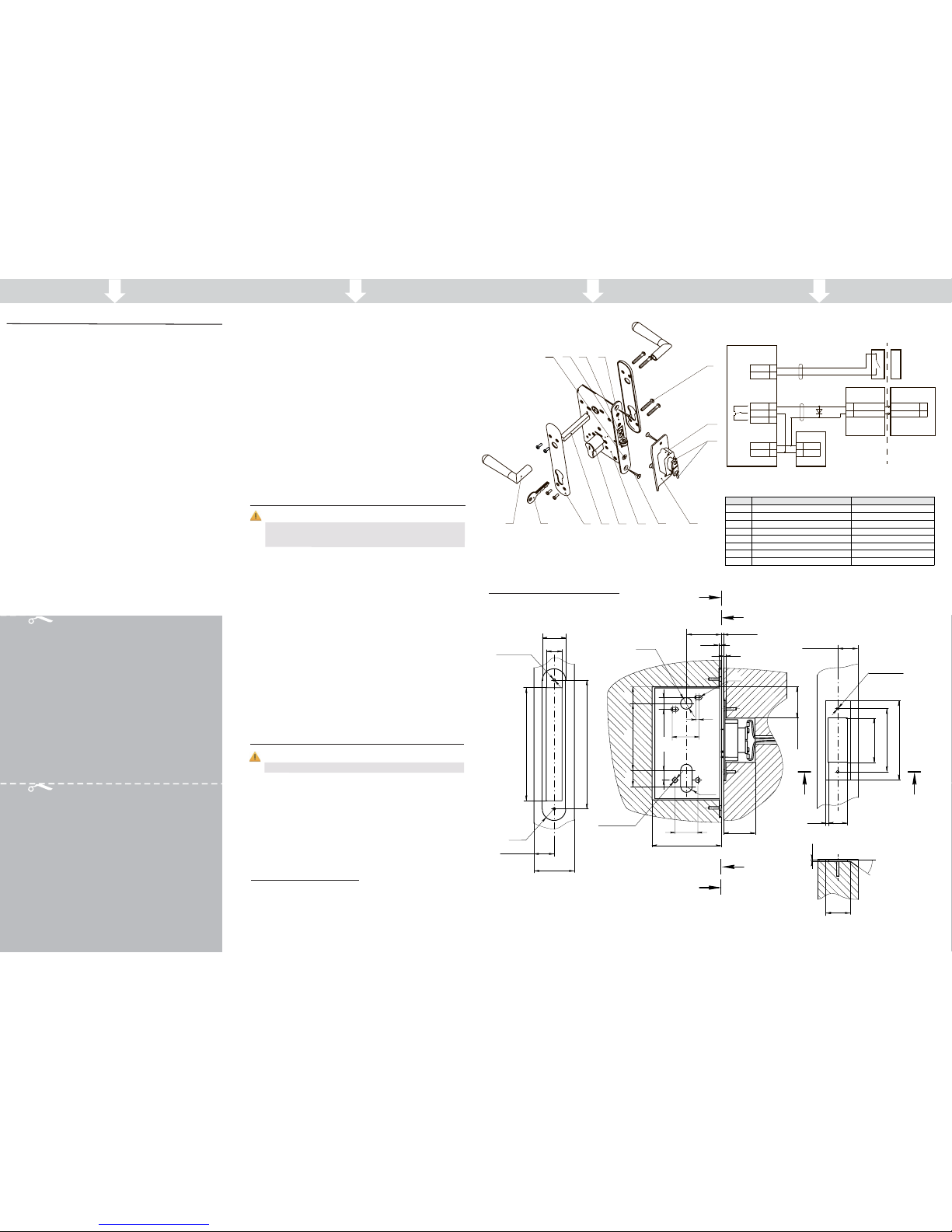
Fig. 1. LB-85.1 electromechanical lock design
- Not included in the delivery set
*
1
2
3
4
3. STANDARD DELIVERY SET
Fig. 3. LB-85.1 electromechanical lock layout
LB-85.1 is a normally-closed electromechanical mortise door lock (hereinafter
– the lock), designed to be used as an operating device as a part of access
control system (hereinafter – ACS) to control light and medium office doors.
Lock features:
• the lock has a uniqu e construction, allowing to connect lo ck control cable
through the strike plate in the door frame, not through the doo r leaf, which
makes installation easier;
• the lock can be installed in wooden and non-metallic doors 38-50 mm thick;
• a universal lock construct ion enables its installation on both right-handed
and left-handed doors;
• the lock is designed for use with standard lock cylinders;
• all components of the lock and strike plate have corrosion-r
esistant coating;
• the lock is resistant to self-opening (for instance, as a result of a hard kick
on the door);
• the lock has low power consumption (max 2 W);
• t he de sign o f the lock does n ot require prev entive maintenance and
lubrication from the customer for the entire period of operation;
• the lock closes automatically at shutting the door;
• the lock can be released with the key or by a signal from ACS;
• de-energized lock can be released with the key only.
The lock with regard to resistance to environmental exposure complies with
GOST 15150-69, category NF4 (operation in premises with climate control).
Operation of the lock is allowed at ambient air temperature from +1°C to
+40°C and at relative air humidity of 75% at +15°C.
The lock has a marking in the form of label located on its housing. The label
contains product name, its serial number, the manufacture date and its main
technical specifications.
The product is packed in a carton box, protecting it from being damaged
during transportation and storage.
Box dimensions (L × W × H) ...................................................... 12×22×4 cm
Gross weight ............................................................................... max. 0.7 kg
Lock storage is allowed indoors at ambient air temperature from -50°С to
+50°С. Storage time in closed package is 12 months.
The lock in the original package can be delivered by means of land (railway
and road), sea and air transport. It is allowed to stack the boxes while in
transit.
2. TECHNICAL SPECIFICATIONS
Attention!
Due to the cont inual prod uct impro vement the m anufacturer
reserves the rig ht to in tro duce am endm ent s in pr odu ct
design without previous notice.
Technical parameters of the lock comply with GOST 538-2001 and
GOST 5089-2011.
DC voltage ..................................................................................... 11 – 13 V
Operational current ................................................................... 0.08 - 0.12 A
Power consumption ........................................................................ max. 2W
Type (fail-safe performance) ................................................ normally-closed
Bolt throw, not less than ..................................................................... 15 mm
Centre-to-centre spacing .................................................................... 85 mm
Dimensions .......................................................................... 85×22×187 mm
Weight .......................................................................... not more than 0.5 kg
Lock type .......................................................................................... cylinder
Unauthorized access protection (UAP) .......... normal, GOST R 51241-2008
Resistance to opening .......................................... І as per GOST 5089-2011
Safety requirements .................................................. GOST R IEC 335-1-94
Electric shock protection class ...................III as per GOST R IEC 335-1-94
MTBF ............................................................. 200000 number of operations
Average lifetime ................................................................................ 8 years
Design and composition of the lock are shown in Fig. 1.
Attention!
Check the delivery set upon product receipt.
Lock ............................................................................................................. 1
Strike plate ................................................................................................... 1
Terminal block .............................................................................................. 1
2
1
1
2
4
5
6
7 8 9
3
11
12
13
14
10
15
1. Lever ; 2. Key; 3. Escutcheon plate fastening screw; 4. Escutcheon plate ;
5. Lever rod ; 6. Lock cylinder ; 7. Lock; 8. Screw 3.9×25;
9. Strike plate; 10. Terminal block; 11. Terminal clamps;
12. Locking mechanism roller; 13. Locking bolt; 14. Forend plate;
15. Lock cylinder fastening screw M5×50
* *
* *
Position Unit
Note
1 Control cable of the ACS controller
2 Reed switch cable
A1 Power supply unit 12V; 0,5А; 6 W
A2 Lock controller
A3 Terminal block
А4 Lock
S1 Reed switch
)AC61EK6P,B51-60WZB(V81–51Suppressor1DV
A2
Input
NO
C
NC
+12V
VD1
Terminal
block
Lock
magnet
S1
A1
A3
A4
Contact 1
Contact 2
1
2
Contact 1
Contact 2
1
2
ACS controller
IN
GND
Output
+U
GND
+12V
+U
GND
The universal construction provides use of standard pin-type lock cylinders, standard
EuroDIN (V DIN 18254), e.g. type 8809, 8209, 8259 produced by company ISEO
(Italy), or lock cylinders of D series by Wilco Supply (type 254 – 274 – 294, 453, 454,
554). The length of lock cylinder fastening screw should not exceed 50 mm.
The lock c ylinder with a se t of keys, doo r levers with fixing eleme nts, reed switch,
control and reed switch cables are not included in the delivery set.
2
1
Fig. 2. LB-85.1 electromechanical lock installation layout
A
A
B
B
A-A
40,5
±1
2,5±1,544
2
2
R3
34
4
1512
R10
27
87
40
21
85
16
2
holes
Ø7
Ø20
2
holes
Ø3,5×30
145
22
16
165
R11
B-B
С
С
С-С
Ø3,5×30
2
holes
3
24
56
80
100
2
35°
31
L / 2
±0,5
L / 2
±0,5
L=38...50
L - Thickness of door leaf
Screw 2.9×13 DIN7982 .......................... ....................................................... 2
Screw 3.9×25 DIN7982 .................. 4 ..............................................................
1 ..................................................................................... etalpmet noitallatsnI
1 .................................................................. launam noitarepo dna etacifitreC
Package box ................................................................................................. 1
1 ............................................................05×5M wercs gninetsaf rednilyc kcoL
Page 2
5
6
7
WARRANTY CARD
Electromechanical Loc kLB-85.1
Serial number
Date of manufacture ____ ____________201__
Quality Con trol Seal
_ _ _ _ _ _ _ _ _ _ _ _ _ _ _ _ _ _ _ _ _ _
Date o f s ale « » ________________201__
____________________________________
(signature, seal)
Cutting line
WARRANTY REPAIR COUPON
Electromechanical Loc kLB-85.1.
Serial number
Date of manufacture ____ ____________201__
Quality Con trol Seal
_ _ _ _ _ _ _ _ _ _ _ _ _ _ _ _ _ _ _ _ _ _
Date o f s ale « » ________________201__
____________________________________
(signature, seal)
Certificate and Operation Manual
www.perco.com
5. MAINTENANCE
6.
PERCo WARRANTY
Electromechanical
Mortise Door Lock
LB 85.1-
РОСС RU.СП26. Н
ТУ 4981-049- 88226999-2014
03587
6 6 5
6 6 5
4.3 Installation order
Reference numbers are given in accordance with Figure 1. Cables used at the
installation are stated in table 1.
Install the lock in the following order:
1. Unpack the lock and check the delivery set.
2. Carv e out t he inst allatio n templa te, whi ch is i ncluded in the standar d
delivery set. Make the hole mark ing for lock cylinder (6), lever rod (5) and,
if needed, of a loca tion slot for lock f orend plate (14) in the door leaf in
the place of lo ck in stall ation usin g the templa te. T emplat e marki ng
corresponds to the one in Fig. 2.
3. If necessary, select the locating pocket for the lock.
4. Carve out ho les and choose t he loca tion sl ot for lock fore nd plat e in
accordance with the marking.
5. Instal
l the lock (7) in the locating pocket of the door and fasten it with two
screws 3.9×25 DIN7982 from the delivery set.
6. Mount the lock cylinder i nside the lock and fix it w ith the screw through
the hole on the lock forend plate.
Attention!
Lock cylinder fastening screw length should not exceed 50 mm.
7. Adjust the door l evers (1) with escutc heon plates (4) in ac cordance with
manu factur er rec ommendatio ns. Ti ghten them w ith th e scre ws wit h
threaded bushing (3). After the installation levers are to turn easily.
8. Check the lock operation at the opened door.
• Sink the locking mechanism roller (12) inside the lock housing. The bolt
will move out of the lock housing (13). The lock will be closed.
• Insert the key (2) inside the lock cylinder and turn it against stop to check
the mechanical unlocking. The bolt will retu
rn into an initial position inside
the lock housing.
• Energize lock flank c ontacts with 12 V power supply to check the auto matic unlocking. The bolt will return into an initial position inside the lock
housing.
• Check several times.
9. Fix the strike plate (9) on the terminal block housing (10) with two screws
2.9×13 from the delivery set.
10. Make carving in the door according to the marking (Fig. 2).
11. Lay the control cable from the ACS to the terminal block installation place
inside the door frame. Use cable №1. The cable laying me thod is deter mined by lock installer and the Customer.
12. Connect the control cable with terminal clamps (11) f rom the ter mina l
block. In order to do that, tighten cable ends into terminal clamps.
Attention!
If the lock is operated as a part of acces s control system (ACS) it
is recommended to install voltage regulator diode BZW06-15B or
P6KE1 6CA, or another mo del with equal param eters on contact
clips (Fig. 3). The voltage regulator diode is used for maintaining
the device which sends the control signal.
13. Mount the strike
plate with the terminal block in the door frame providing
2-3 mm spacing between the strike plate and the forend when the door is
closed. The channel of the strike plate must lay symmetrical to bolt’s cross
section.
Attention!
The locking mechanism roller should not g et into the channel of
the strike plate! Otherwise, at closing the door, it can get locked
with the moving roller and the n it will be impossibl e to open the
door without damaging the lock.
14. Mount the strike plate on the door frame with two screws 3.9×25 from the
delivery set.
15. Install and connect the reed switch. Use cable №2 in table 1 for connec-
tion. Installing the reed switch ensure firm contact closure a t closing the
door.
Disassembling of the lock should be made in the reverse order.
Warning!
• Do not use the lock at power supply voltage other than specified
in its technical specifications.
• Do not use the lock in operation conditions other than specified
in the following Manual.
• Do not use the l ock in ho stile env ironment with atmo spheric
content of acids, bases, oils, etc.
The lock is a normally-closed device, which means that in normal condition it
is locked at the closed door. In this case lever turning is blocked. After lock
release the do
or is opened by turning the lever (approximately at 20º).
Unlocking is performed by:
• Turning the key in the lock cylinder. The key is to be turned against stop
and kept in such a position until the door opens.
• Terminal block clamps’ energizing until the door opens. Energizing is
operated by the ACS controller. At that the potential operation mode
should be set for lock control output. Door open
ing detection is performed
according to the reed switch status.
At lock release the bolt moves inside the housing and the door can be
opened. At door opening the locking mechanism roller automatically moves
out of the lock housing.
At door closing the locking mechanism roller is sunk into the lock housing,
which initiates bolt moving-out and automatic locking.
PERCo (the Manufacturer) warrants th
at the LB85.1 electromechanical
mortise door lock (the Product) complies with applicable statutory safety
requirements, electromagnetic compatibility provided that the instructions on
storage, installation and operation, given in the Assembly & Operation Manual
are observed.
The warranty period is 5 (five) years commencing from the date of sale.
Should there be no date of sale on the warranty card,
the warranty period
shall commence from the date of manufacture.
Within the warranty period the Product is repaired free of charge at the
Manufacturer’s site.
The Warranty does not cover Products with external mechanical damages or
disassembled by the Customer.
Transportation cost to and back from the place of repair shall be borne by the
Customer.
Upon lock purchase request the date of sale stamp
in the warranty certificate
and check the completeness of the delivery set as per the Manual.
In case any questions arise during the Product assembly or operation,
PERCo Company is always ready to give you necessary technical support.
4. ASSEMBLY AND INSTALLATION
4.1 General recommendations
The lock shall be installed by qualified professionals who have studied this
Manual before the installation work.
Attention!
In order to pro vide stable lo ck operation a n accurate ±1,5 mm
verti cal mou nting of the str ike pl ate wit h te rmi nal b loc k
regarding locking b olt is required. The l ock operates normally
if the s pacing between the forend plate and the strike plate is
2.5±1.5 mm.
4.2 Cable length
Table 1. Cables used.
№
Application
Max
length
Type of cable
An example
of cable
1
ACS controller
cable
30m
Twin cable with
0.75 mm
cross-section
2
HO3VV-F,
HO5VV-F 2×0.75
2
Reed switch
cable
30m
Twin cable with
0.2 mm
cross-section
2
RAMCRO
SS22AF-T
2×0.22 or CQR-2
PERCo
Polytechnicheskaya str., 4, block 2
194021, Saint Petersburg
Russia
Tel: +7 812 247 04 64
E-mail: [email protected]
www.perco.com
 Loading...