


Controller
CT/L-04.2
ASSEMBLY AND OPERATION MANUAL

Controller
CT/L-04.2
Assembly & Operation Manual

CONTENTS
1 APPLICATION..............................................................................................................4
2 OPERATION CONDITIONS .........................................................................................4
3 TECHNICAL SPECIFICATIONS ..................................................................................5
4 DELIVERY SET............................................................................................................6
4.1 Standard delivery set ..............................................................................................6
4.2 Optional equipment .................................................................................................6
5 DESCRIPTION .............................................................................................................7
5.1 Design and operation ..............................................................................................7
5.2 Controller boards.....................................................................................................8
5.3 IP-address setting .................................................................................................10
5.4 Controller configuration templates.........................................................................11
5.5 Signals of inputs....................................................................................................12
5.5.1 Inputs IN1 – IN4............................................................................................12
5.5.2 Inputs DUA, DUSt, DUB, FA.........................................................................13
5.6 Settings of output signals ......................................................................................14
5.6.1 Relay outputs OUT1 – OUT4........................................................................14
5.6.2 Outputs OK1 and OK2..................................................................................14
5.6.3 Outputs LdA, LdSt, LdB ................................................................................15
5.7 Parameters of signals received on inputs ШC1 and ШC2 .....................................15
5.7.1 “Standard” input configuration.......................................................................15
5.7.2 “AL” input configuration.................................................................................16
5.8 Connection to RS-485 interface ............................................................................17
6 MARKING AND PACKAGING ....................................................................................18
7 SAFETY REQUIREMENTS........................................................................................18
7.1 Installation safety requirements.............................................................................18
7.2 Operation safety requirements ..............................................................................18
8 INSTALLATION ..........................................................................................................19
8.1 Cable lengths ........................................................................................................19
8.2 Installation order....................................................................................................20
8.2.1 Controller installation ....................................................................................20
8.2.2 Door control configuration.............................................................................22
8.2.3 Turnstile and electromechanical gates configuration ....................................24
8.2.4 Vehicle checkpoint configuration ..................................................................26
8.2.5 RC-panel configuration .................................................................................28
8.2.6 Connecting a Fire Alarm Device ...................................................................29
8.2.7 Connecting the alarm lines ...........................................................................29
8.2.8 Connection of optional equipment ................................................................30
9 CONFIGURATION......................................................................................................33
10 UPDATE OF EMBEDDED SOFTWARE.....................................................................34
11 OPERATION ..............................................................................................................35
11.1 Operation modes of ACS ......................................................................................35
11.2 Indication of ACS, events and controller configurations ........................................36
11.3 Troubleshooting ....................................................................................................37
11.3.1 The controller does not work.........................................................................37
11.3.2 Failure of communication with PC ................................................................37
12 MAINTENANCE .........................................................................................................39
13 TRANSPORTATION AND STORAGE........................................................................41
Appendix 1. Instruction on connection of the card capture reader .....................................42
Appendix 2. Instruction on connection of the alcohol detection device ..............................45
Appendix 3. Instruction on connection of the controller through PoE-splitter .....................47
Appendix 4. Instructions for connecting biometric readers manufactured by Suprema .....49
Appendix 5. CT/L-04.2 Controller Web-interface. User Manual .........................................50
2

CT/L-04.2 Controller
Dear Customer!
Thank you for purchasing a controller manufactured by PERCo.
Please follow the instructions given in the Manual carefully,
and this quality product will provide many years of trouble-free use.
This Operation Manual (hereinafter – the Manual) provides information on technical
specifications and operation of CT/L-04.2 controller. The Manual aims to provide correct
operation of the controller and complete use of its technical capabilities. The Manual
contains data on installation and maintenance, and also a reference section.
The Manual is active together with Technical description of PERCo-Web and also with
certificates of devices connected to the controller.
Abbreviations adopted in the Manual:
ACM – access control mode;
ACS – access control system;
AL – alarm line;
LAN – local area network;
OD – operation device;
PC – personal computer;
PS – power supply;
RC– remote control;
RTC – real-time clock;
WRC – wireless remote control.
3

Assembly & Operation Manual
1 APPLICATION
CT/L-04.2 controller (hereinafter – the controller) is a part of PERCo-Web ACS.
The controller supports connection up to 8 different PERCo readers (Sect. 5.8) and
enables to organize up two two-way passages or up to four one-way passages.
Depending on configuration (Sect. 5.4) the controller can control the following ODs (in
different combinations):
One electromagnetic or electromechanical lock that supports two-way passage;
Up to four electromagnetic or electromechanical locks that support one-way
passage;
One turnstile or gate;
One boom barrier or an automatic gate of vehicle checkpoint.
Besides that, there can be connected up to 8 units of CL-201 lock controllers of the
second level, controlling one-way passage.
2 OPERATION CONDITIONS
The controller, with regard to resistance to environmental exposure complies to GOST
15150-69 category NF4 (operation in premises with climate control).
Operation of the controller is allowed at ambient air temperature from +1°C to +40°C and
relative air humidity up to 80% at +25°C.
4

CT/L-04.2 Controller
3 TECHNICAL SPECIFICATIONS
Operating voltage ................................................................................................... 12±1.2V
Consumption current (12V) .................................................................................. max. 0.2A
Power consumption ............................................................................................ max. 2.5W
Communication interface standard ................................................... Ethernet (IEEE 802.3)
Ethernet data transfer speed .......................................................................... 10/100 Mbps
Number of controlled ODs ...................................................................................... up to 41
Number of reading devices ....................................................................................... up to 8
Interface of reading devices ..................................................................................... RS-485
Number of access cards (users) ..................................... from 10,000 to 50,000 (see Note)
Event memory capacity
2
............................................. from 230,000 to 870,000 (see Note)
Note:
The user is able to change the memory allocation of the controller via the
Web-interface. Other options of memory allocation (see Appendix 5, Clause 3.4):
- 50 000 cards and 230 000 events (by default).
- 40 000 cards and 390 000 events.
- 30 000 cards and 550 000 events.
- 20 000 cards and 710 000 events.
- 10 000 cards and 870 000 events
Number of relay outputs for OD control ............................................................................. 4
Number of additional “open collector” outputs ................................................................... 2
Number of inputs with line control for short circuit and line break
(controlled by “dry contact” outputs) ................................................................. up to 8
Number of alarm lines ............................................................................................... up to 2
Number of remote control inputs ............................................................................... up to 4
Number of remote control indication outputs ..................................................................... 4
Electric shock protection class ...................................................................... III (IEC 61140)
Mean lifetime ........................................................................................................... 8 years
Dimensions ............................................................................................... 205×189×45 mm
Weight ............................................................................................................... max. 1.8 kg
1
Depends on the selected controller configuration (see Section 5.4).
2
Events from connected CL-201 controllers are stored in the memory of CT/L-04.2 controller.
5

Assembly & Operation Manual
4 DELIVERY SET
4.1 Standard delivery set
Controller ........................................................................................................................... 1
Jumper ............................................................................................................................. 11
Resistor С2-33H-0.25-4.7 kOhm ....................................................................................... 2
Suppressor 15-18 V ........................................................................................................... 4
Mounting hardware:
plastic dowel .................................................................................................................. 3
screw ............................................................................................................................. 3
self-adhesive cable tie mount ........................................................................................ 3
nylon cable tie 100 mm .................................................................................................. 5
Package ............................................................................................................................. 1
Certificate ........................................................................................................................... 1
Operation manual .............................................................................................................. 1
4.2 Optional equipment
Power supply ..................................................................................................................... 1
WRC kit 1............................................................................................................................ 1
PoE-splitter2 ....................................................................................................................... 1
Siren .................................................................................................................................. 1
CL-201 lock controllers ............................................................................................. up to 8
AU-05 system time display ................................................................................................ 1
1
WRC kit consists of a receiver and transmitters (tags) with operation range up to 40 m.
2
PoE-splitter – allows energizing of the controller via Ethernet network. Splitter can be used with
network switches that support PoE technology and that are compatible with IEEE 802.3af
standard.
6

CT/L-04.2 Controller
5 DESCRIPTION
5.1 Design and operation
The controller is produced in the form of electronics module in metal housing with a
removable cover. The cover houses power indication.
Following features are installed in the controller:
non-volatile memory;
non-volatile RTC-timer (real time clock);
8P8C (RJ45) connector for Ethernet local network;
housing opening sensor (the “tamper switch”).
The controller operates with cards the code of which does not exceed 64 bits.
The controller is able to store in non-volatile memory:
up to 50 000 card identifiers;
up to 230 000 events in the event log with the date and time of the event1.
The controller provides:
connection via Ethernet (IEEE 802.3) interface;
support of TCP/IP protocol suite (ARP, IP, ICMP, TCP, UDP, DHCP);
support of application layer of communications protocol of PERCo-Web system;
updating of embedded software through Ethernet.
On default, the controller has:
unique MAC-address (specified in the certificate and on the item board);
IP-address (specified in the certificate and on the item board);
Subnet mask (255.0.0.0);
IP-address of the gateway (0.0.0.0).
Following ways to set up IP-address, gateway and subnet mask are provided at the stage
of system configuration:
work with default settings;
manual input;
receipt from DHCP server.
Readers are connected to RS-485 interface of the controller. Connection variants are
provided in the Sect. 5.8.
Following optional equipment may be connected:
up to two Al-01 indication blocks with infrared-receiver;
up to four door sensors (reed switches);
two passage sensors (PASS-outputs of a turnstile);
up to four RC-buttons (“Exit”) for a lock;
one RC-panel of a turnstile (swing gate);
up to seven devices sending commands to additional inputs,
one AU-05 system time display;
emergency unlock devices Fire Alarm.
1
In case of event log overflow the oldest events will be replaced with the new ones (events are
deleted by blocks consisting of 256 events).
7

Assembly & Operation Manual
The controller as a part of ACS provides:
operation in ACM: “Open”, “Control”, “Security” 1, “Closed”;
saving of the set mode in the non-volatile memory, to avoid the turn-off of the mode in
case of power failure;
support of local and global control of zonality and verification.
The controller as a part of security alarm system provides:
connection and control of two alarm lines2;
connection of light and sound alarm devices;
possibility of arming and disarming of the protected zone;
sending of alarm notifications to central surveillance panel.
5.2 Controller boards
The controller includes two boards – top board (processor module) and bottom board
(process execution module). The connecting blocks XS1 – XS3 of the top board are fitted
in the connecting blocks XP1 – XP3 of the bottom board. The boards of the controller are
shown on Figure 1. The purpose of connecting blocks is given in the Table 1.
Figure 1. The top and bottom boards of the controller
1
The mode “Security” is available only for configurations “Controller for lock control” and
connected CL-201 lock controllers.
2
Depends on chosen controller configuration (see Sect. 5.4).
8

CT/L-04.2 Controller
Table 1. The purpose of connecting blocks of the bottom board
Contact
Name of the
physical contact
in the Web-
interface
Purpose
Connector ХТ1 (IN)
IN1 Input 1 “Door sensor #1” or “Input for PASS A signal”
GND –
“Common”
IN2 Input 2
“Door sensor #2” or “Input for PASS B signal”
or “Additional input IN #2”
IN3 Input 3
“Door sensor #3” or “Additional input IN #3”
GND –
“Common”
IN4 Input 4
“Door sensor #4” or “Additional input IN #4”
Connector ХТ2 (RC)
FA Input 10
“Input for emergency unlock (passage opening) Fire alarm”
GND –
“Common”
DUA Input 7
“Control input of the OD1 from the RC-button” or “Control input of
direction A from the RC-panel”
DUSt Input 8 “Input STOP from the RC-panel” or “Additional input IN #8”
DUB Input 9
“Control input of the OD2 from the RC-button” or “Control input of
direction B from the RC-panel” or “Additional input IN #9”
LdA Output 7
“Output for indication of direction A on the RC-panel” or “Additional
output OUT #7 (TTL- level)”
LdSt Output 8
“Output for indication STOP on the RC-panel” or “Additional output
OUT #8 (TTL- level)”
LdB Output 9
“Output for indication of direction B on the RC-panel” or “Additional
output OUT #9 (TTL- level)”
Buzz – “Output for sound indication on the RC-panel”
Connector ХТ3 (ОC)
ОК2 Output 6 “Additional output OUT #6 (open collector)”
ОК1 Output 5 “Additional output OUT #5 (open collector)”
+12V – “Output of +12VDC power for outputs ОК1 and ОК2”
Connector ХТ4 (+12VDC)
+12V –
GND –
“Input of controller + 12VDC power from external PS”
Connector ХТ5 (RS-485)
+12V –
GND –
“Output of +12VDC power for readers”
A –
“Connection of line A via RS-485”
B –
“Connection of line B via RS-485”
Connector ХТ6 (OUT1)
NO1 normally open contact
C1 central contact
NC1
Output 1
normally closed contact
“Relay control output OD #1”
Connector ХТ7 (OUT2)
NO2 normally open contact
C2 central contact
NC2
Output 2
normally closed contact
“Relay control output OD #2” or
“Additional output OUT #2”
9

Assembly & Operation Manual
Contact
Name of the
physical contact
Purpose
in the Web-
interface
Connector ХТ8 (OUT3)
NO3 normally open contact
C3 central contact
NC3
Output 3
normally closed contact
“Relay control output OD #3” or
“Additional output OUT #3”
Connector ХТ9 (OUT4)
NO4 normally open contact
C4 central contact
NC4
Output 4
normally closed contact
“Relay control output OD #4” or
“Additional output OUT #4”
Connector ХТ10 (AL)
ШС1+ “Alarm line input AL #1 (contact +)”
ШС1-
Input 5 (loop)
“Alarm line input AL #1 (contact -)” or “Additional input IN #5”
ШС2+ “Alarm line input AL #2 (contact +)”
ШС2-
Input 6 (loop)
“Alarm line input AL #2 (contact -)” or “Additional input IN #6”
Controller has on the top board:
XP1 – connector to choose the method of the IP-address of the controller; by default,
the jumper is not installed - user mode (Sect. 5.3);
S1 – connector for the Ethernet cable.
Controller has on the bottom board:
XP1 – XP3 – connecting blocks for the top board;
XP4 – connecting block for power indication on the housing;
XP5.1, XP5.2 – XP8.1, XP8.2 – connectors (in pairs) to select the type of connected
lock (see Section 8.2.2):
jumpers pair are removed – if a standard electromechanical or electromagnetic
lock is connected to the corresponding output,
jumpers are installed – locks of LB- or LBP-series are without installed door
sensor (reed switch). The controller traces the passage on condition of the
contact group of the lock;
XP9 and XP10 – are connectors for selection of input ШC1 and ШC2 configurations
where (see Section 5.7):
jumper in position 1-2 – ''alarm line'' input type,
jumper in position 2-3 – ''standard'' input type.
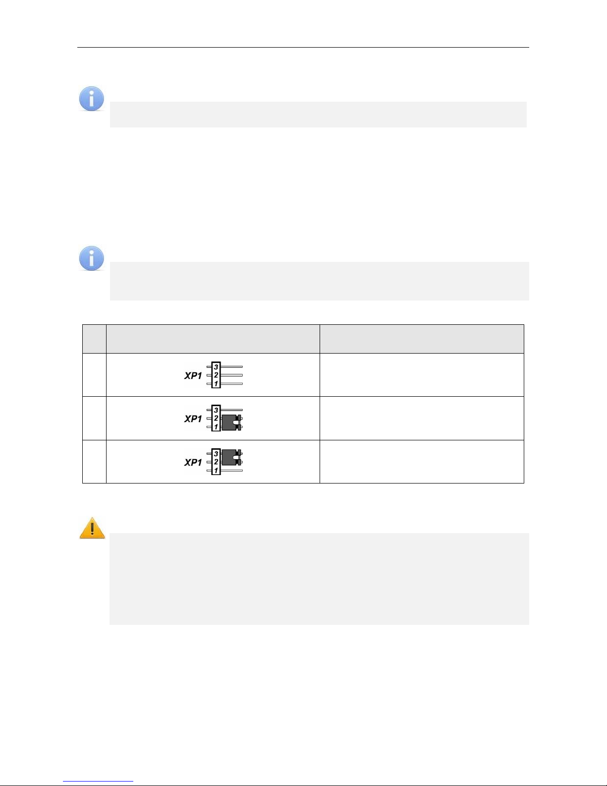
5.3 IP-address setting
The way of IP-address setting is selected by installation or removing of jumper on XP1
connector on the controller top board.
Attention!
Jumpers should be installed and removed only when the power is off.
Following ways of IP-address setting are possible (see Table 2):
1. User mode. Jumper is removed.
If the IP-address (gateway, subnet mask) is not changed by the user, the controller
works with default settings: IP-address and MAC-address are specified in the
certificate of IP-stile and on the controller board; subnet mask 255.0.0.0;
IP-address of the gateway 0.0.0.0.
10
CT/L-04.2 Controller
If the IP-address (gateway, subnet mask) is changed by the user, the controller
starts to work with the new settings immediately without switching power supply.
Note:
It is possible to change network settings of the controller from PC via Web-interface
or software. The controller and PC must be on the same subnet.
2. “IP MODE”. Jumper is in the position 1–2.
Work in networks with dynamic allocation of IP-addresses, the controller can
receive IP-address (gateway, subnet mask) from DHCP-server.
3. “IP DEFAULT”. Jumper is in the position 2–3.
The controller works with default settings: IP-address and MAC-address are
specified in the certificate of IP-stile and on the controller board; subnet mask
255.0.0.0; IP-address of the gateway 0.0.0.0.
The password for controller is reset.
Note:
User settings of IP-address (gateway, subnet mask), if they were set, are saved
during the switch into “IP DEFAULT” mode. The controller will operate with them at
next turn-on, if jumper is not installed.
Table 2. Jumper installation on XP1 connector
№ Jumper position on XP1 Method of specifying IP addresses
1
User mode
2
“IP MODE”
3
“IP DEFAULT”
5.4 Controller configuration templates
Attention!
Change of the controller configuration template, adding of the of the second level
controllers and optional card readers are available only using the Web-interface
of the controller (see Appendix 5, Clause 4.1).
If you change the template, you delete the configuration and internal responses
of all resources of the controller. The configuration “Default” is set for resources
of the selected configuration. Meanwhile the information of access cards
identifiers, data of users, rights and access settings are saved.
Following configuration templates are available for the controller:
1. The controller to operate the turnstile (without additional locks);
2. The controller to operate the turnstile and one one-way lock;
3. The controller to operate the turnstile and two one-way locks;
4. The controller to operate the turnstile and one two-way lock;
5. The controller to operate the vehicle checkpoint (without additional locks);
11

Assembly & Operation Manual
6. The controller to operate one vehicle checkpoint and one one-way lock;
7. The controller to operate one vehicle checkpoint and two one-way locks;
8. The controller to operate one vehicle checkpoint and one two-way lock;
9. The controller to operate one one-way lock (without alarm lines);
10. The controller to operate one one-way lock with one alarm line;
11. The controller to operate one one-way lock with two alarm lines;
12. The controller to operate two one-way locks (without alarm-lines);
13. The controller to operate two one-way locks and one alarm line;
14. The controller to operate two one-way locks and two alarm lines;
15. The controller to operate three one-way locks (without alarm lines);
16. The controller to operate three one-way locks with one alarm line;
17. The controller to operate four one-way locks;
18. The controller to operate one two-way lock (without alarm lines);
19. The controller to operate one two-way lock and one alarm line;
20. The controller to operate one two-way lock and two alarm lines;
21. The controller to operate one two-way lock and one one-way lock (without alarm lines);
22. The controller to operate one two-way lock and one one-way lock with one alarm line;
23. The controller to operate one two-way lock and two one-way locks;
24. The controller to operate two two-way locks (without alarm lines);
25. The controller to operate two two-way locks with one alarm line.
By default, the configuration №1 “The controller to operate the turnstile (without additional
locks)” is configured.
5.5 Signals of inputs
5.5.1 Inputs IN1 – IN4
The controller provides status control of four inputs controlled by “dry contact” or “open
collector” (OK): IN1-IN4. Connection to the outputs is performed via XT1 connecting block
of the controller bottom board (Figure 1 and 3).
Note:
To create a high-level signal on all input contacts IN1 – IN4, resistors with 2 kOhm
resistance, connected to +3.3V power line, are used.
Inputs can be used for following connections:
IN1:
o door sensor 1 (reed switch),
o PASS output of a turnstile,
o passage sensor of a vehicle checkpoint;
IN2:
o door sensor 2 (reed switch),
o PASS output of a turnstile,
o optional equipment (IN #2);
IN3, IN4:
o door sensor 3, 4 (reed switch),
o optional equipment (IN #3, IN #4).
12

CT/L-04.2 Controller
Signals activation depends on description of their default status in Normal status of
contact parameter in PERCo-Web software):
If input is described as Opened, it is activated by a turn-on of low-level signal
relative to GND contact. In such case a normally opened relay contact or a scheme
of open collector output may be a control element.
If input is described as Closed, it is activated by a turn-off of low-level signal relative
to GND contact. In such case a normally closed relay contact or a circuit of open
collector output may be a control element.
Note:
Input IN1 is configured as “Closed” by default.
If according to the configuration of the controller input IN2, IN3 or IN4 is used to
connect the door sensor / passage sensor / PASS, that by default is configured
as Closed with the possibility of further changes.
Control element “relay contact” should provide following characteristics of signals:
Minimum commutating current ........................................................................ max. 1 mA
Closed contact resistance
(with resistance of the connection cable)................................................ max. 300 Ohm
Control element of circuit with open drain output should provide following characteristics of
signals:
Voltage at the closed contact
(low-level signal at input of the controller)...................................................... max. 0.8 V
5.5.2 Inputs DUA, DUSt, DUB, FA
The controller provides status control of four inputs under control of “dry contact” or “open
collector” (OK): DUA, DUSt, DUB, FA. Connection to the inputs is performed via XT2
connecting block of the controller bottom board.
Note:
To create a high-level signal on all input contacts DUA, DUSt, DUB, FA, resistors
with 1 kOhm resistance, connected to +3,3V power line, are used.
Inputs can be used for following connections:
DUA, DUSt, DUB:
o RC-buttons,
o RC-panel (WRC),
DUSt, DUB:
o optional equipment (IN #7, IN #8);
FA:
o emergency unlock devices (passage opening) Fire Alarm.
Activation and characteristics of signals of the control element are specified in the
Sect. 5.5.1.
Note:
Input FA is uniquely configured as “Closed”.
Input DUA is uniquely configured as “Opened”.
If according to the configuration of the controller input DUSt or DUB used to
connect RC-buttons, it is uniquely configured as Opened without any possibility
being modified.
13

Assembly & Operation Manual
5.6 Settings of output signals
5.6.1 Relay outputs OUT1 – OUT4
The controller is equipped with four relay outputs OUT1 – OUT4. Connection to the
outputs is performed via XT6 – XT9 connecting blocks of the controller bottom board.
Every output has a complex group of contacts: normally open NO, normally closed NC and
common output C.
Outputs may be used for (Figure 3):
OUT1:
o as a control output of operation unit OD #1;
OUT2, OUT3, OUT4:
o as a control output of OD #2, OD #3 and OD #4,
o as outputs to control optional equipment (OUT #2, OUT #3, OUT #4).
Characteristics of output signals:
Maximum commutating voltage of direct current ......................................... max. 30 V
Maximum commutating voltage of alternate current .................................... max. 42 V
Maximum commutated direct/alternate current for outputs Out ..................... max. 5 A
Resistance of closed contact .............................................................. max. 0.15 Ohm
Control outputs support potential and pulse operation modes of OD. Selection of mode is
performed with Operation mode of control output parameter of OD.
In potential mode of OD:
In case of single passage relay output is activated for a period of time, set in
software by Unlocked state holding time software parameter or till the moment of
passage.
In case OD is set into “Open” mode relay output is activated till the mode change.
In pulse mode of OD:
In case of single passage relay output is activated for a period of time, set by
Control pulse duration parameter of OD. In such case OD remains unlocked until
the passage is performed.
In case OD is set into “Open” mode output is activated for a period of time, set by
Control pulse duration parameter of OD, and after that it will be activated each
time for the same period in one second after the normalization of OD.
Activation of inputs IN1 – IN4, configured as door sensor or signal PASS, define that the
passage was performed in the set direction.
5.6.2 Outputs OK1 and OK2
The controller is equipped with two outputs “open collector”: OK1 and OK2 (in
configuration OUT #5 and OUT #6, Figure 3). Connection to the outputs is carried out via
XT3 connecting block of the controller bottom board.
+12VDC supply is derived to the same connecting block for easy connection.
Outputs can be used for following functions:
connection of light and sound alarm devices,
sending of alarm notifications to central surveillance panel,
connection of other optional equipment.
Characteristics of output signals:
Maximum commutation voltage of direct current ...........................................max. 30 V
Maximum commutated current...................................................................max. 0.25 A
14

CT/L-04.2 Controller
5.6.3 Outputs LdA, LdSt, LdB
The controller is equipped with three outputs type “TTL”: LdA, LdSt, LdB. Connection should
be performed to the contacts of XT2 connecting block of the controller bottom board.
Outputs can be used (Figure 3):
as outputs of connection of indication of the RC-panel,
as outputs of control of other optional equipment (OUT #7, OUT #8, OUT #9).
Characteristics of output signals:
Maximum voltage of direct current ................................................................. max. 3 V
Maximum current....................................................................................... max. 0.01 A
5.7 Parameters of signals received on inputs «ШC1» and «ШC2»
The controller provides the status control of two inputs ШC1 and ШC2. Connection to the
inputs is carried out via the connecting block XT10 of controller bottom board.
Every input can be used as input of alarm line or as standard input to connect the lock
RC-button or to connect optional equipment (IN #5, IN #6), see Figure 3. The input
selection depends on the selected controller configuration and the position of the jumper
on the connector XP9 or XP10 on the controller bottom board. Installation of the jumper in
the position 2-3 corresponds to the configuration “standard input”.
Attention!
When you select the controller configuration with one or two ALs (see Sect. 5.4),
you need to put jumpers on the controller bottom board in the position 1-2 (see
Figure 1):
on the connecting block XP10 with configuration “1 AL”,
on the connecting blocks XP9 and XP10 with configuration “2 ALs”.
5.7.1 “Standard” input configuration
Jumper XP9 (for ШC1) or XP10 (for ШC2) is in the position 2-3. The controller provides the
control input status ШC1- ÷ GND (ШC2- ÷ GND) under control output type “dry contact” or
“open collector” (OК).
Note:
To create a high-level signal on inputs contacts ШC1- and ШC2- relative to GND,
the resistors with 1kOhm resistance are used. They are connected to +5 V power
line. The resistors with 392 Ohm are connected to the minus of power supply.
In this configuration input can be used:
ШC1- ÷ GND:
o as input for connection of RC-button for the lock (RC OD #3);
o as input for connection of optional equipment (IN #5).
ШC2- ÷ GND:
o as input for connection of RC-button for the lock (RC OD #4);
o as input for connection of optional equipment (IN #6).
Activation of all signals depends on description of their initial status in Normal status of
contact parameter in PERCo-Web software:
If input is described as Opened, it is activated by a turn-on of low-level signal relative
to GND contact. In such case a normally open relay contact or a scheme of open
collector output may be a control element.
If input is described as Closed, it is activated by a turn-off of low-level signal relative to
GND contact. In such case a normally closed relay contact or a circuit of open
collector output may be a control element.
15

Assembly & Operation Manual
Note:
If according to the configuration, input of the controller is used for connection of the
RC-button, that it is configured as “Opened” without any possibility being modified.
Control element “relay contact” should provide following characteristics of signals:
Minimum commutating current ........................................................................ max. 1 mA
Closed contact resistance
(with resistance of the connection cable) ............................................. max. 300 Ohm
Control element of circuit with open collector output should provide following
characteristics of signals:
Voltage at the closed contact
(low-level signal at input of the controller .................................................... max. 0.8 V
5.7.2 “AL” input configuration
Jumper XP9 (for ШC1) or XP10 (for ШC2) is in the position 1-2.
Only security detectors may be used as detectors, connected to alarm line:
Electrical contact detectors and magnetic contact detectors (reed switches, fuses);
Those that have relay on output (4-wire line).
Table 3. Status and thresholds of alarm line
Alarm line resistance, Ohm Status of alarm line defined by a device
Configuration: “Security”
Less than 2 kOhm Violation – short circuit
2,4 kOhm - 7 kOhm Normal
More than 9 kOhm Violation – line break
Configuration: “Security with tamper-evidence examination of detectors housings”
Less than 1,3 kOhm Violation – short circuit
1,5 kOhm - 2,3 kOhm Normal
2,5 kOhm - 3,6 kOhm Violation – detector housing is opened
4 kOhm - 6 kOhm Violation – detector activation
More than 7 kOhm
Violation – detector activation and detector housing is opened or
line break
Specifications of input signals of alarm line:
Voltage in alarm line .................................................................................................... 5 V
Short circuit current in alarm line ................................................................... max. 12 mA
Resistance of remote element .......................................................................... 4.7 kOhm
Resistance of alarm line wires
(without regard to resistance of remote element) .................................... max. 1 kOhm
Resistance of alarm line wires during tamper-evidence examination of detectors
housings (without regard to resistance of remote element) ................ max. 0.22 kOhm
Leakage resistance between alarm line wires and “ground”....................... min. 20 kOhm
Note:
Alarm line specifications are controlled by their resistance.
AL integration time – maximum period of time during which the change of alarm line
resistance is not regarded as a violation and does not cause the turn of alarm line into
alarm state.
16

CT/L-04.2 Controller
When AL is armed, its resistance is constantly measured with necessary averaging. AL
integration time is set by Violation duration parameter and it is equal to 70 ms or 300 ms.
The requirements for detecting the AL state at these AL integration time are shown in
Table 4:
Table 5. Alarm line integration time
Integration time (Violation duration) 70 ms 300 ms
Alarm line violations should not cause a device to detect “violation” alarm line
status, in case they were in process during the period of time not exceeding
50 ms 250 ms
Alarm line violations should cause a device to detect “violation” alarm line
status, in case they were in process during the period of time exceeding
70 ms 300 ms
5.8 Connection to RS-485 interface
Readers, Al-01 display unit with infrared-receiver, CL-201.1 lock controller and AU-05
system time display are connected to the controller via RS-485 interface. The
communication line of the RS-485 interface is being implemented over twisted pair with the
polarity observance according to the principle of the direct topology of the «common bus»
(the communication line is paved in series to all devices, and the devices to the
communication line are connected in parallel, the contact A to the line A, the contact B to
the line B).
At the end of the communication line of RS-485 interface should be mounted limit
resistors-terminators Roк with nominal value of 120 Ohms. On products with built-in
terminal resistor, which are not end devices of the communication line, it is necessary to
remove the jumper by cord “disconnection of end-of-line resistor”. The position of jumper is
indicated in the operational documentation of a specific product. If the controller is located
at one of the end of the communication line, the terminal resistor with nominal value of 120
Ohms is installed between A and B contacts of XT5 connecting block.
When connecting to RS-485 interface, follow the instructions of the connected device and
the scheme presented in Figure 3. To connect a communication line of RS-485 to the
controller, the cable type №2 is applied (Table 6).
Attention!
When installing each type of device (readers, controllers, display units) they need to
set different addresses, otherwise devices of the same type with the same
addresses will not work. The address is determined by the status of the jumper
(jumper) "number" on the chassis or on the product board (see the operating
documentation for this product).
Contact +12V and GND of XT5 connecting block can be used as power supply for
devices under condition that the maximum load current must not exceed 0.5A.
Following variants of reader connection are possible (Figure 3):
Up to eight IR-03.1, IR-04.1, IRP-01.2, IR-10 card readers, IC-02.1, IC-05 card capture
readers (in any combination).
Up to eight MR-07.1 card readers.
Up to eight readers with Wiegand (Wiegand-26, -34, -37, -40, -42) interface. The
connection requires up to 4 AC-02.1 interface converters. Each converter allows you
to connect two Wiegand readers on the RS-485 bus. Connection diagram and
description of indication of the readers are given in the operational documentation of
the interface converter.
17

Assembly & Operation Manual
6 MARKING AND PACKAGING
The marking label of the controller is placed on the back of the housing. The marking label
provides following information concerning the controller:
trade mark and contact details of the manufacturer;
name and number of model;
serial number;
date and month of manufacture;
allowed power voltage range;
consumption current.
The controller board contains labels with default MAC-address and IP-address of the
controller.
The controller is packed into a paperboard box, preventing it from damages during
transportation and storage.
7 SAFETY REQUIREMENTS
7.1 Installation safety requirements
Installation and technical maintenance of the controller should be performed by qualified
staff, after getting acquainted with the Operation manual and safety rules. Installation
should be performed in accordance with general electrical and work safety rules.
Attention!
All connections and jumper installations should be carried out only when the
equipment is powered off and power supply is disconnected.
During mounting use only proper tools.
Cabling should be performed in accordance with general requirements for
electrical equipment.
Do not use the controller if it is not properly installed and connected.
7.2 Operation safety requirements
Operation should be performed in accordance with general electrical and work safety
rules.
Do not use!
The controller under conditions that do not comply with the requirements of
Section 2 of this Manual.
The controller at supply voltage that does not comply with the requirements of
Section 3 of this Manual.
The device in hostile environment that contains acids, alkalis, oils etc.
Power supply should be used accordingly to safety rules given in the Operation manual.
18

CT/L-04.2 Controller
8 INSTALLATION
Installation should be performed in accordance with work safety noted in Sect. 7.1.
Installation should be done in accordance with local building requirements.
8.1 Cable lengths
Cables for mounting are shown in Table 6.
Mounting of communication lines should comply with EIA/TIA RS-422A/485 standards.
Do not lay cables at a distance less than 50 cm from a source of electromagnetic
interference.
Crossing of all cables with power cables is allowed only at a right angle.
Lengthening of cables should be performed by soldering only.
All cables, entering controllers, should be fixed with plastic ties to self-adhesive cable
tie mount, included into delivery set and installed inside the housing. Lay and fix
cables using plastic fixing brackets, if necessary.
After cables are laid, check if there are no line breaks and short circuits at all lines.
It is not allowed to lay power cables for lock, sensor cables, remote control cables and
reader cables at a distance more than 1 m from ground cables.
Table 6. Cables used for installation
№ Equipment
Cable
length, m,
max
Cable type
Cross
section,
mm² min.
able example
1 Ethernet (IEEE 802.3) 100
Four twisted
pairs (starting
from Category 5)
4×2×0.52 F/UTP2Cat5e
Reader, card capture
reader, Al-01 indication
block
50 (total)
2
CL-201 lock controller,
AU-05 system time
display
1200 (total)
Twisted pairs
(starting from
Category 5)
0.2
2×2×0.52 F/UTP2Cat5e
3 Power source 10 Twin cable 0.75
Flat cord with sheath
and outer sheath of
PVC
4
RC-button (“Exit”); Door
sensor (reed switch);
Additional sensor
(to input of the controller);
Additional equipment
(to output of the
controller)
30 Twin cable 0.2
RAMCRO SS22AF-T
2×0.22
CQR-2
5 Remote control board 40 Eight-core cable 0.2 CQR CABS8 8×0.22c
7 Lock 30
Double-core
cable
0.75
PVC twin cable
2×0.75
8 Turnstile 30 Six-core cable 0.2 CQR CABS6 6×0.22c
9 Vehicle checkpoint 30 Four-core cable 0.2 CQR CABS4 4×0.22c
10 Alarm line Twin cable 0.5 PVC twin cable 2×0.5
19

Assembly & Operation Manual
8.2 Installation order
Connection to the controller is performed in accordance with scheme shown on
Figures 3 - 13 with the use of cables from Table 6. The position of connecting blocks on
the controller’s board is presented on Figure 1.
Installation of connected devices (turnstiles, locks, power supply, etc.) is performed
according to the instructions given in technical documents of corresponding devices.
8.2.1 Controller installation
1. Unpack the box and check completeness of package contents according to Sect. 4.
Make sure that the equipment is not mechanically damaged.
2. Define the place for installation of the controller. Location of the controller should
comply with operational conditions. When choosing a location, make sure that it will be
convenient to perform service maintenance of the controller.
Attention!
Do not install the controller at a distance less than 1 m from a source of
electromagnetic interference.
3. Mark and drill holes in the surface to install the controller and connect cables in
accordance with Figure 2. Lay and mount communication cables, power cables and
Ethernet cables to the location.
Figure 2. Marking of holes for the controller installation
20

CT/L-04.2 Controller
Figure 3. Common scheme of connections
21

Assembly & Operation Manual
4. Fix the controller with three screws through holes in the controller housing (use dowels
from the delivery set if necessary).
5. Select the way to set IP-address of the controller (Sect. 5.3) and install a jumper on
XP1 connector in accordance with the Table 2, if necessary.
6. Connect Ethernet cable to S1 connector of the top board of the controller.
7. Connect power source cable to XT4 connecting block of the lower board of the
controller in accordance with the scheme, shown on Figure 3.
Note:
The order of power connection of the controller via PoE-splitter is described in
Appendix 3.
8. Connect necessary equipment to RS-485 controller interface (Sect. 5.8).
9. Connect t
he rest of necessary equipment. Follow the next recommendations in
connection of:
electromechanical (electromagnetic) locks (Sect. 8.2.2);
turnstile (Sect. 8.2.3);
vehicle checkpoint (Sect. 8.2.4);
RC-panel (WRC) (Sect. 8.2.5);
emergency unlock devices Fire Alarm (Sect. 8.2.6);
alarm lines (Sect. 8.2.7);
other optional equipment (Sect. 8.2.8).
Note:
Installation order of external verifying devices to the controller is described in
Appendix 2 (an example of the alcohol detection device).
8.2.2 Door control configuration
When you connect the lock (latch) to the controller, follow the next recommendations:
1. To dissipate static electricity, is recommended to ground the housing or locking bar of
the lock. In case of lock installation on a metal door, it is recommended to ground the
door leaf. It is necessary to use the cable with cross section minimum 0.75 mm
2
.
Attention!
If the connected lock is not equipped with built-in spark protection circuit, it is
necessary to use the suppressor from the delivery set or Schottky diode for
operating current not less than 1A (1N5819). The suppressor is installed close to
the lock (VD1 on Figure 4).
If the connected electromagnetic lock is not equipped with demagnetizing circuit,
it is necessary to install a bidirectional suppressor from the delivery set (VD1 on
Figure 4).
If the controller is connected via PoE-splitter, it is recommended to use only
electromechanical locks with spark protection diodes (VD1 on Figure 4), type
1N5819. The use of suppressor in such case is FORBIDDEN.
22

CT/L-04.2 Controller
Figure 4. Connection schemes of the locks
2. Connect the lock (the latch) to XT6 or XT9 connecting blocks on the lower board of the
controller is made in accordance with scheme (Figures 3 - 5).
3. If you need to connect
remote control button, connect it to XT2 (XT10) of lower board
of the controller (Figure 5).
4. The reed switch is connected to XT1
connecting bloc of lower board (Figure 5). The
door sensor with the lock controlled by OUT1 is connected to IN1 input, OUT2 to IN2,
etc. The door sensor must be mounted that when the door is closed, the sensor can
always actuate.
Note:
The locks LB-, LBP-series do not require mounting of the door sensor (the
CT/L-04.2 controllers can trace the door opening based on the contact group of the
lock). In this case, is necessary to installed jumpers on the lower board of the
controller: for OUT1 – XP5.1 and XP5.2, for OUT2 – XP6.1 and XP6.2, for OUT3 –
XP7.1 and XP7.2, for OUT4 – XP8.1 and XP8.2 (Figure 1).
23

Assembly & Operation Manual
5. Emergency devices Fire Alarm are connected to XT2 connecting block of bottom
board of the controller (in this case it is necessary to remove jumper by cord), Figure 5
and Sect. 8.2.6.
6. Fix cables with plastic ties to self-adhesive cable tie mount, included into delivery set,
by installing them inside of the controller the housing.
Figure 5. Connection scheme for RC-button and door sensors
8.2.3 Turnstile and electromechanical gates configuration
Notes:
The Device output mode of operation parameter of OD should be in Potential
for PERCo turnstiles.
The Registration of the passage after ID card presentation parameter of OD
should be in Yes for swing gate WMD-05S and WMD-06.
Follow the next recommendations to connect the turnstile (the gate) to controller:
1. To dissipate static electricity, is recommended to ground the housing of turnstile. It is
necessary to use the cable with cross section minimum 0.75 mm.
2. Connect the turnstile (the control unit of the turnstile) to XT1, XT6, XT7 connecting
blocks of the controller bottom plate in compliance with the scheme (Figure 6).
3. Connect the swing gate (the control unit of the turnstile) to XT1, XT6, and XT7
connecting blocks of the bottom board of the controller in compliance with the scheme
(Figure 7).
Note:
Connection scheme of power circuit of the controller and the turnstile (the gate) in
case of connection via PoE-splitter is given on Figure 19.
4. Connect RC-panel (or WRC) to XT2 connecting block of the lower board of the
controller in compliance with the scheme (Figure 10).
5. Fix cables with plastic ties to self-adhesive cable tie mount, included into delivery set,
by installing them inside the housing of the controller.
24

CT/L-04.2 Controller
Figure 6. Connection schemes of “Turnstile control” configuration
25

Assembly & Operation Manual
Figure 7. Connection schemes of the gates
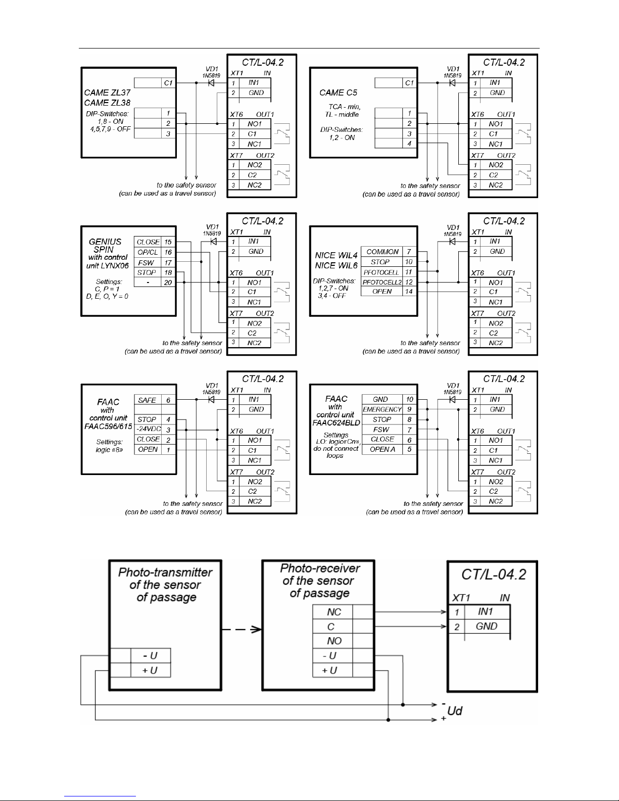
8.2.4 Vehicle checkpoint configuration
When installing a controller, is necessary to correspond with operation logic of control unit
of vehicle checkpoint:
Operation of control unit of vehicle checkpoint is performed via two relays – when
passage is allowed OUT1 relay is activated and held, sending “Open” signal. After a
vehicle has passed through the checkpoint (detected by passage detector), or after
waiting period is over, OUT1 relay switches to normal, after that OUT2 relay is
activated for 1 sec, sending “Close” signal. Also, OUT2 relay is activated for 1 sec by
Close button of RC-panel.
If Automatic closing function is turned on in the control unit of OD of vehicle
checkpoint, operation from vehicle checkpoint is performed via one relay. When
passage is allowed OUT1 relay is activated and held, sending “Open” signal. After a
vehicle has passed through the checkpoint (detected by passage detector), or after
waiting period is over, OUT1 relay switches to normal, after that boom barrier is closed
automatically (it is recommended to set a minimum possible waiting period for
automatic closing). In such case OUT2 relay it is not used.
Installation of OD of vehicle checkpoint to the controller is performed in accordance with
instructions, given in technical documents of corresponding devices. Follow the next
recommendations (the position of the connecting blocks on the controller board. 1):
1. To dissipate static electricity is recommended to ground the housing of the OD.
Grounding should be performed with a cable with wire section not less than 0.75 mm2.
2. General connection schemes of OD of vehicle checkpoint re given on Figure 8.
26
CT/L-04.2 Controller
Figure 8. Connection scheme of boom barriers to the controller of vehicle checkpoint
Figure 9. Connection scheme of passage sensors
27

Assembly & Operation Manual
Note:
Output normalization parameter of OD should be set into After closing mode.
If operation is performed via one relay, Automatic closing function should be
turned on in the control unit of OD of vehicle checkpoint, in such case a
minimum waiting period for automatic closing should be set - Regulation
Т.C.V. (for CAME) and PAUSE TIME (for NICE).
3. Connect passage sensor to XT1 connector block of the bottom board of the controller
in accordance with the scheme, shown on Figure 9. Use cable №4 for connection
(Table 6). If several sensors are connected, their outputs should be turned on
successively.
For CAME and GENIUS boom barriers infrared security sensors should be used as
passage sensors, connected to the control unit of ODs of vehicle checkpoint in a
standard way. In such case they are connected to the controller of vehicle checkpoint
with parallel connection.
For NICE and FAAC boom barriers the general principle of connection of infrared
sensor to the controller of vehicle checkpoint is depicted in examples of connection
schemes for control unit of corresponding model. Instead of VD1 diode some other
decoupling circuit might be necessary.
Attention!
To ensure correct passage detection of a vehicle with a trailer or other parts
transparent for passage sensors, it is recommended to install several spacedapart sensors, or to set value of Recovery delay of passage sensors
parameter sufficient for passage of transparent part of a vehicle by the sensor.
If there is no passage sensor is necessary to put tick at Absence of passage
sensor parameter in the software. In such case malfunction of OD of vehicle
checkpoint is possible, due to the impossibility to choose the optimal passage
period.
4. Fix cables with plastic ties to self-adhesive cable tie mount, included into delivery set,
by installing them inside the housing of the controller.
8.2.5 RC-panel configuration
The controller in the relevant configuration allows connecting the RC-panel to control
turnstiles, swing gates or OD of vehicle checkpoint. To connect the RC-panel to the
controller are used:
Three inputs to control the passage: DUA, DUSt, DUB;
Four outputs to control the indication of the RC-panel: LdA, LdSt, LdB, Buzz.
The connection is made to contacts of XT2 connecting block (Figure 10).
The inputs DUA, DUSt and DUB in these configurations of the controller are activated by
low-level signals (normally opened contact) regarding GND contact. Settings of signals
that can be used for connection of the RC-panel are specified in Sections 5.5.2 and 5.6.3.
28

CT/L-04.2 Controller
Figure 10. Connection scheme of RC-panel or WRC of “Turnstile control” and
“Vehicle checkpoint control” configurations
8.2.6 Connecting a Fire Alarm Device
In case of fire alarm or other emergency situation, there is possibility of automatic
unlocking (passage opening) of all ODs connected to the controller board and the
controllers of the second level. As an exception are ODs which are in operating mode
“Security” (the possibility of emergency unlocking are configured in their configuration).
Emergency release (emergency passage opening) of ODs is produced by the command of
the emergency device Fire Alarm. The emergency device Fire Alarm is connected to the
input of the controller FA (contacts FA and GND of XT2 connecting block, Figures 3, 5,
10). If the device Fire Alarm is absent, on the input should be installed jumper by cord
(default installation). Settings for signal FA are indicated in Sect. 5.5.2. When the control
signal is applied to the input FA, the controller operates in the mode Fire Alarm. In this
mode, all connected devices open for passage in both directions. Other control commands
are ignored.
8.2.7 Connecting the alarm lines
To connect Alarm lines, follow the next recommendations:
1. In case of use of the controller inputs for connection of Alarm lines, switch the jumper
on XP9 and XP10 connecting blocks of the bottom board of the controller according to
Sect. 5.7. The position of connecting blocks is indicated on Figure 1.
2. Alarm lines are connected to XT10 connecting block of the lower board of the
controller, cable type №10 (Table 6).
29

Assembly & Operation Manual
Figure 11. Connection scheme for configuring “ШC” inputs as “AL”
8.2.8 Connection of optional equipment
To connect optional equipment, follow the next recommendations:
1. The typical connection schemes of the optional equipment are shown on Figures 12,
13, 14.
Figure 12. Connection scheme of optional equipment to relay outputs
30

CT/L-04.2 Controller
Figure 13. Connection scheme of optional equipment to controller inputs
31

Assembly & Operation Manual
Figure 14. Connection scheme of optional equipment to “Open collector”
outputs
2. To connect the optional equipment, use cable type №4 (Table 6).
3. Fix cables with plastic ties to self-adhesive cable tie mount, included into delivery set,
by installing them inside the housing of the controller.
Attention!
To connect the optional equipment with inductive load (Rn) to the outputs, it is
necessary to use spark protection diode (VD1 on Figure 12). For example, Schottky
diode for operating current not less than 1A (1N5819).
32

CT/L-04.2 Controller
9 CONFIGURATION
The main controller configuration (select the configuration, adding and removing
controllers of the second level and optional readers) is possible only via the Web-interface
of the controller (Appendix 5).
The order of configuration of the controller:
1 Verify all connections (Sect. 8.2). Connect the power source to the circuit with voltage
and frequency indicated in its operational documentation. Turn on the power source,
on the controller housing should light up LED indication. It means that the controller is
switched on.
2 Connect to the Web-interface of the controller via Ethernet network (Appendix 5,
Clause 2).
Note:
The computer should be in the same subnet with the controller. At first turn-on, it
might be necessary to change network settings of the computer. The controller is
equipped with IP-addresses from 10th subnet on default. Add IP-address:
10.x.x.x (x- random numbers) and subnet mask 255.0.0.0. to TCP
/
IP
additional settings of the computer. No such servers or services like DNS and WINS
are necessary. After turn-on network settings of the controller can be changed to
settings recommended by system administrator in the software or via the Webinterface.
3 Via the Web-interface perform the initial configuration of the controller according to the
connected equipment:
note the settings of the memory of the controller (on default is “50 000 access cards
230 000 events”), Appendix 5, Clause 3.4;
select the controller configuration (on default is “Turnstile configuration”),
Appendix 5, Clause 4.1;
if necessary, add to the configuration lock controllers of the second level CL-201
and optional readers, Appendix 5, Clause 4.2.
4 Further configuration of the controller and devices connected to it can be changed
either via Web-interface or with optional software installed on the computer:
PERCo-SL01 “local software” (does not require licensing);
PERCo-SL02 “local software with visual verification”;
Note:
Local software does not support configurations of the controller with the vehicle
checkpoint.
Network software PERCo-Web.
Note:
You may buy optional software from official PERCo distributors. Also, specified
software, the procedure of his licensing and electronic versions of the operating
manual are available on the website of the company PERCo http://www.perco.com
in the section Support > Software.
33

Assembly & Operation Manual
10 UPDATE OF EMBEDDED SOFTWARE
To update embedded software and format the memory controller, the program “Firmware
updater” is used. This program goes together with files “Software to change firmware”. The
current version of the program is available on the website of the company www.perco.com
in the section Support > Software.
Also, update embedded software and format the memory is possible using the Webinterface of the controller in the section Diagnostic (Appendix 5, Clause 9).
34

CT/L-04.2 Controller
11 OPERATION
When operating the controller, follow security measures indicated in Sect. 7.2.
After the configuration, the controller can operate in the following modes:
Without connection to the security system server.
If connection to Ethernet network and PC is also unavailable, the controller can perform
the following functions:
Receives identifiers of the presented cards from the readers, and grants or denies
access, depending on their presence in the list.
Controls connected ODs.
Arms and disarms the protected zone; controls alarm line and ODs in “Security”
mode; activates additional outputs in “Alarm” mode.
Records events in event log in the memory of the controller.
Supports functions of local location monitoring, T&A and double-check access.
If the controller is connected to the network and other controllers of the system, the
function of global location monitoring is available.
Connected to the PC with “Local software” installed:
Data from event log is automatically transferred to the program database at each
start-up of the program. Data can be also transferred with the use of the related
button in the program.
Data (name) owners are stored in the program database.
Verification function is available if “Local software with verification” is installed.
With connection to the security system server.
Besides those that are supported in the stand-alone, the following functions are available:
Data from event log are automatically transferred to the database on security
system server.
Availability of verification function depends on installed extensions of network
software.
11.1 Operation modes of ACS
The change of operation mode is carried by the command of software or Web-interface.
Note:
In configuration “Controller for one two-way lock” and “Controller for vehicle
checkpoint” should be made simultaneously for both directions.
Operation mode in configuration “Controller for turnstile” is set independently for
each direction.
The controller, which is operated as a part of ACS, provides following operation modes of
ODs (indication of ACS is given in the Table 7):
Operation mode “Open” - the mode of free passage.
OD will be unblocked before the change of operating mode.
Pressing of buttons of RC-panel and RC-button (“Exit”) are ignored.
Operation mode “Control” - the basic operation mode as a part of ACS.
OD is blocked.
When an access granting card is presented to the reader, OD is unblocked for
Unblocked state holding period.
35

Assembly & Operation Manual
Operation mode “Closed” is mode of passage prohibition.
OD will be unblocked before the change of operating mode.
Pressing of buttons of remote control board and RC-button (“Exit”) are ignored.
When any card is presented, an event of access violation is registered.
Operation mode “Security”1.
OD will be unblocked before the change of operating mode.
Pressing of buttons of RC-panel is ignored.
Protected zone is armed including the selected OD.
Passage through the OD (forced entry) sets the system into “Alarm” state.
11.2 Indication of ACS, events and controller configurations
Indication of operation modes, states and reactions of the controller to the presented
identifiers is performed on connected remote readers and indication blocks. Possible
variants of indications are shown in Table 7.
Note:
When reading an access control card in any operation mode, an audible signal
lasting 0.2 seconds is performed, yellow indicator changes his state for
0.2 seconds. The state of other indicators is not changed.
After the access is granted, indication is turned on for Unblocked state holding
period or until the passage is performed. When access is denied indication is
turned on for 1 second.
Table 7. Indication of the controller
Indicators
Card presentation
Operation
mode
Green Yellow Red
Sound
(sec.)
Configuration is not selected No 5 Hz 5 Hz 5 Hz off
Activating of input Fire Alarm
Any card
1.3/0.2
2
off off off
“Open”
on off off off
“Control”
off on off off
“Security”
off 1 Hz 1 Hz off
No
“Closed”
off off on off
“Open”
on off off 0.2
“Control”
Card is not authorized for access
“Security”
Any card
“Closed”
off off on 0.5
“Open”
“Control”
on off off 0.2
Card is authorized for access
“Security”
off off on 0.5
“Open”
“Control”
Card is authorized for access and for
arming/disarming
“Security”
1
on off
off 0.2
1
Operation mode is available only for configuration “Controller for the locks” and for connected
CL-201 lock controllers.
2
Blinking (going off briefly) – 1.3 seconds is on, 0.2 seconds is off.
36

CT/L-04.2 Controller
Indicators
Operation
Card presentation
Sound
mode
Green Yellow Red
(sec.)
Change to the
mode “Security”
“Security”
off 1 Hz 1 Hz 0.2
“Open”
Waiting for double
check
Before to return
to initial mode
“Control”
off off 1 sec 1
Waiting for verification Any off 2 Hz off 0.2
11.3 Troubleshooting
The elimination of possible malfunctions listed below is made by the buyer. If the fault
persists, we recommend you to contact one of the service centers of PERCo company. A
list of service centers is given in the Certificate.
Before the diagnostics you need to open the housing of the controller.
Each relay output of the controller is equipped with diagnostic LED indicator for
convenience. The turn on/off of LED indicators identifies that relay is activated/deactivated.
Possible faults:
11.3.1 The controller does not work
Possible causes of the controller malfunction:
1. Malfunction of connection lines used to connect various devices (reader, indication
block with infrared detector, lock, turnstile, door sensor, remote control button, siren,
etc.) to the controller – check connection lines.
2. Malfunction of power source of the controller – check the power source.
3. Malfunction of connection lines used to connect various devices (reader, indication
block with infrared detector, lock, turnstile, door sensor, remote control button, siren,
etc.) to the controller – check connection lines.
4. Identical addresses of connected devices are set – set different addresses. Check
the connection of address lines.
5. Failure of devices connected to the controller – check the operation of devices.
6. Failure of radioelectronic components, installed on the controller board – contact
PERCo service in order to replace this board.
11.3.2 Failure of communication with PC
Possible causes of this malfunction:
1. Network Settings in the computer are missing – set IP-address and subnet mask of
the computer. The controller should be connected either directly to network connector
of network card of the computer or to the same Hub / Switch the computer is
connected to.
2. Invalid password of the controller. Check the password entered in the software.
1
In the mode “Security” after presentation of access card disarming the protected zone occurs
disarming of protected zone with OD and unlocking of OD for Unlocked state holding period.
After this time expires the OD switches to the operating mode stated before capture of protected
zone (“Open” or “Control”, if the previous mode was “Closed” that operating mode is “Control”).
37

Assembly & Operation Manual
3. Malfunctions of the computer (software, databases etc.).
To detect this malfunction, start the command:
ping x.x.x.x
where x.x.x.x is the IP-address of the controller.
If there is a communication, you will see lines similar to the following:
Reply from x.x.x.x: bytes=32 time<10ms TTL=128
If there is no communication (response), check routing Settings of your network.
4. Malfunctions of equipment of Ethernet network, installed between the computer
and the controller: hub, switch and other network equipment including communication
cables.
To detect this malfunction, start the command:
ping x.x.x.x -l 576
where x.x.x.x is the IP-address of the controller.
If there is a communication and standard minimal packets (576 bytes) are not
fragmented, you will see lines similar to the following:
Reply from x.x.x.x: bytes=576 time<10ms TTL=128
In such case IP-packets are not fragmented to the size less than 576 bytes and the
selected connection should be operative.
If the positive answer is not received, the problem might be with network switching
equipment that fragments IP-packets to the size less than 576 bytes. Check settings of
this equipment, enlarge the size of MTU. This parameter is usually specified as
MaxMTU or IPMTU.
5. If several variants of switching are possible, use command:
ping x.x.x.x -l 576 -t
By switching with various variants, look at response time and choose the connection
with the fastest response.
6. Malfunctions of the controller. Failure of elements providing connection via Ethernet
interface (IEEE 802.3).
To detect this malfunction, have a look at two indicators, installed 8P8C (RJ45)
connector of Ethernet connection:
LINK – connection:
o Green light is on – the controller detects connection to Ethernet network,
o Green light is off – the controller does not detect connection to Ethernet
network;
ACT – data exchange
o Yellow light is blinking – the controller detects data exchange via Ethernet
network,
o Yellow light is off – the controller does not detect data exchange via Ethernet
network.
If the controller does not detect connection to Ethernet network (light indicators are off),
connect it to the cable that connects the other controller or computer.
If the controller still does not detect connection to Ethernet network or the communication
is not reestablished, contact PERCo service in order to repair this controller.
38

CT/L-04.2 Controller
12 MAINTENANCE
Technical staff performing maintenance of the controller should be acquainted with
construction and operating procedures of the controller.
All works should be done by high-skilled electricians.
Information about scheduled maintenance is recorded in the log of maintenance and
monitoring of the technical condition of means of the security fire alarm system.
Respecting of periodicity, technological order and methods of execution of maintenance
work are required.
Please refer to section 7 “Safety requirements” of this Manual when performing technical
maintenance.
Following types and periodicity of maintenance work should be provided:
planned work according to the regulation №1 – once per three months;
planned work according to the regulation №2 – receiving of two or more false
alarms from the protected object within 30 days.
List of work for the regulations is shown in Tables 8 and 9.
De-energize the controller prior to maintenance.
All control instrumentations should be calibrated.
Maintenance of the lock controller CL-201 consists in periodic cleaning of the controller
housing and checking all the connections to the cable coming out of the controller (see
Operation manual CL-201).
Maintenance of other devices of the system, such as locks, turnstiles, swing gates,
security detectors, power supply, etc. refer to operating manuals for these devices.
39

Assembly & Operation Manual
Table 8. List of maintenance works according to the regulations №1 (checklist №1)
Work Procedure
Devices,
instrument,
equipment
Norms and
events
1.1 Disconnect power supply from AC
current, clean up the controller and power
supply surface from dust, dirt and damp.
Rags, brush, flat
brush
There should not
be traces of dirt
and damp.
1.2 Remove the controller and power supply
housing, clean up surface from dust and
damp. Measure the voltage of the extra
power supply. In case you may charge or
replace the battery.
Screwdriver,
rags, flat brush,
measuring
device
Voltage should
correspond to
certificate on the
battery (min.
12,6V)
1.3 Remove dust, dirt, corrosion from the
surface of connecting blocks, jumpers and
protectors
Rags, flat brush,
grease
It should not be
corrosion and dirt
1.4 Verify compliance of the denomination
and the condition of the fuses
1.5 Verify connection of external circuits to
connecting blocks of the controller
Screwdriver
It should conform
to the scheme of
the external
connections is
loosen. Restore
connection, if the
wire is broken off.
Replace the wire,
if insulation is
damaged
1 External inspection, cleaning of the controller
1.6 Tighten the screws on the connecting
blocks where the mount
Screwdriver
Wires and
insulation should
not be damaged
2 Operability test
2.1 Check of the controller by simulating the
actuation of detectors in accordance with the
configuration of the resources.
Indication on the
controller,
corresponding to
events.
Formation of
signals at the
outputs according
to their
configuration.
Table 9. List of maintenance works according to the regulations №2 (checklist №2)
Work Procedure Norms and events
1. External
inspection, cleaning
of the controller
1.1 Complete on 1.1-.6 of
checklist №1.
2. Functional test
2.1 Check the operation
under Sect. 11 in accordance
with selected configuration.
Switching on of indication on the controller
according to Sect. 11.2. Forming of relay
outputs according to their configuration.
40

CT/L-04.2 Controller
13 TRANSPORTATION AND STORAGE
The controller in the original package should be transported in closed freight containers or
in other closed type cargo transport units.
The storage of the controller is allowed indoors at ambient temperature from -20°C to
+40°C and at relative air humidity up to 98% at +25°C.
41

Assembly & Operation Manual
APPENDICES
Appendix 1. Instruction on connection of the card capture
reader
The card capture reader is designed to operate as a device for reading, capturing and
keeping Proximity cards issued to visitors and meant for return at exit.
In PERCo-Web the controller CT/L-04.2 operates with the card capture reader, built-in
card capture readers of the PERCo turnstiles, connection of third party card capture
readers is possible. The procedure of configuring of the controller and the card capture
reader is described in the Guide of the administrator of these systems.
An example of connection of the PERCo card capture readers is shown on Figures 15 and
16. Any available inputs and outputs are used in the current controller configuration.
The controller controls the card capture reader by sending the input signal “Capture the
card” to the board of the card capture reader. One of the additional outputs of the
controller, which connects the input “Capture the card”, should be configured in software
so that upon presentation of the card to the proper card reader, the output is activated.
After card capturing, the card capture reader passes the signal “Card captured”, which the
controller uses as the confirmation of permission of passage in the required direction
through the OD. One of additional controller inputs should be configured in software that
when it is activated by the signal “Card captured”, the controller opens the operating
device in the required direction.
The card capture reader can generate other signals (for example, the signal of trouble in
his work, signal of filling container) that can be applied to the free inputs of the controller
by configuring them to required reactions (activation of appropriate sirens, etc.).
Settings of inputs and outputs of the card capture reader should correspond to Settings of
inputs and outputs of the controller (Sect. 5.5, 5.6, 5.7).
If the card capture reader has an input for indicating the passage permission (for example,
IC-05), then, when opening the passage in the direction controlled by the card capture
reader, the appropriate command must be given. To do this, you can use the controller's
free output by configuring it as the output of the pass enable indication in that direction
(see Figure 16) or using the control output for the external indication of the OD, if it is (in
the PERCo turnstiles are the outputs "Light B", "Light A” of the CLB board).
42

CT/L-04.2 Controller
Figure 15. Scheme of connection of the card capture reader IC-02.1
43
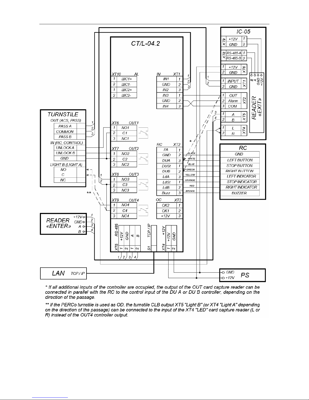
Assembly & Operation Manual
Figure 16. Scheme of connection of the card capture reader IC-05
44
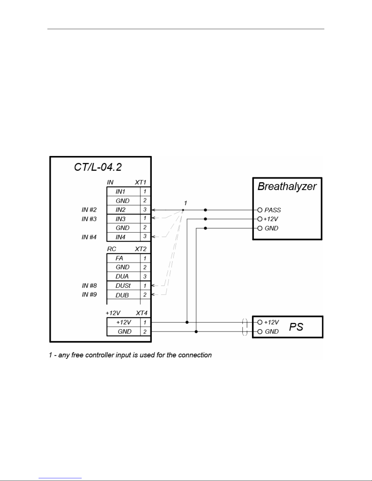
CT/L-04.2 Controller
Appendix 2. Instruction on connection of the alcohol detection
device
It is possible to connect to the controller the alcohol detection device (hereinafter
breathalyzer) to monitor the temperance of employees and visitors when they enter and/or
leave the company (one breathalyzer is for one direction of passage).
Operation of the controller with the breathalyzer is possible only after configuring it in
PERCo-Web software. The procedure of configuration is described in the Guide of the
administrator of these systems.
The breathalyzer has single control output where the signal PASS is removed. The
scheme on Figure 17 is used to connect the breathalyzer (any free input is used in the
current configuration of the controller).
Figure 17. Connection scheme of the breathalyzer
with single control output
45
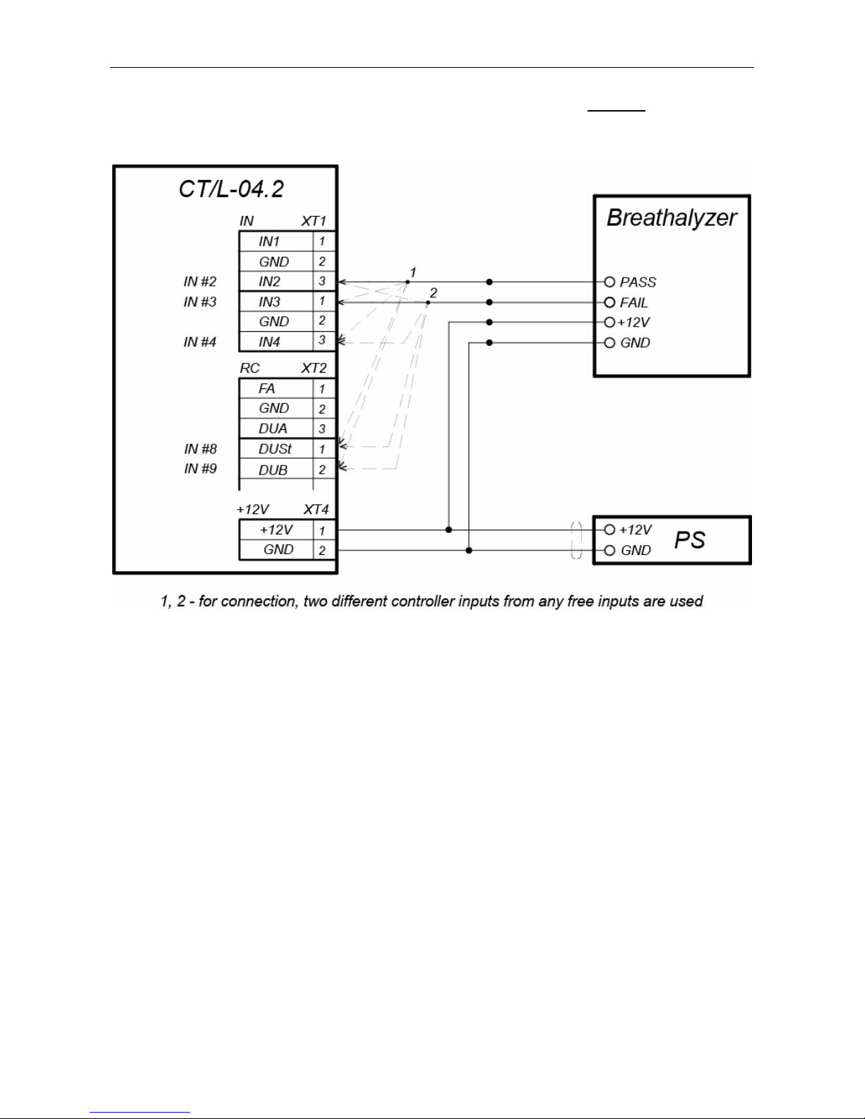
Assembly & Operation Manual
The breathalyzer has two control outputs where the signal PASS and FAIL are removed.
The scheme on Figure 18 is used to connect the breathalyzer (two different free inputs are
used in the current configuration of the controller).
Figure 18. Connection scheme of the breathalyzer
with two control outputs
46
CT/L-04.2 Controller
Appendix 3. Instruction on connection of the controller
through PoE-splitter
Attention!
Instruction provided refers to the splitters included in supplementary equipment
delivery set.
Total power consumption of the controller and of all the devices powered by it
should not exceed 12 W. It is also recommended to leave min 10% reserve
power.
Splitter description
PoE-splitter (hereinafter – splitter) is designed for energizing equipment, connected via
Ethernet network. Splitter operates with any network commutators (hereinafter – Switch),
supporting technology of electric power transmission via PoE twisted pair wire and
compatible with IEEE 802.3af standard.
Splitter is designed as a block of electronics in a plastic housing featuring the following
outputs:
Con 1 – output for Ethernet cable from Switch connection;
Con 2 – output for Ethernet controller cable connection;
Con 3 – power output for controller power cable connection.
Note:
For some models of splitters output voltage is chosen with the switcher. Operating
with PERCo equipment it is necessary to turn the switcher into “12V” mode.
Requirements for connecting devices
The characteristics of power consumption of the controller when connected through splitter
should meet the following requirements:
Admissible value of supply voltage .............................................................. 12±1.2 V
Minimum total current ............................................................................ min. 120 mA
Maximum total current consumption (12V) ................................................... max 1 A
Maximum total power consumption ........................................................... max 12 W
In order to avoid exceeding the total power consumption is not recommended to provide
power from the controller to connected optional equipment (siren, passage sensors, etc.)
and controllers of the second level. The controller powered from the splitter can be
connected up to four readers and OD (Table 10).
Table 10. OD with power connection through PoE-splitter
Types of controller configurations OD
“Controller to operative to control the
locks”
Electromechanical lock (LC, LB and
LBP-series – up to 4pcs).
“Controller to operate the turnstile”
Turnstile with power consumption
no more than 9W
T-5
TTR-04.1
TTD-03.1
TTD-03.2
47

Assembly & Operation Manual
Procedure of controller connection
Cables used in installation are mentioned in Table 6. When you connect the controller
through the splitter, follow the next procedure:
1. Find the mounting place of the splitter. It is recommended to install the splitter inside
of controller housing (do not install the splitter from the controller at distance more
than 2m).
2. Connect Ethernet cable from the controller to Con2 connector of the splitter.
3. Connect the power supply to Con3 connector. If necessary OD can be connected to
Con3 connector too. Connection scheme is shown on Figure 19 (plug for connection
to connector is on delivery kit of the splitter).
4. Connect Ethernet cable from Switch to Con1 connector of the splitter.
5. Connected device will be powered after verification between Switch and the splitter.
In case if you need to power off the controller, it is sufficient to disconnect Ethernet cable
(from Switch) from Con1 connector of the splitter.
Figure 19. Connection scheme of the controller through PoE-splitter
48
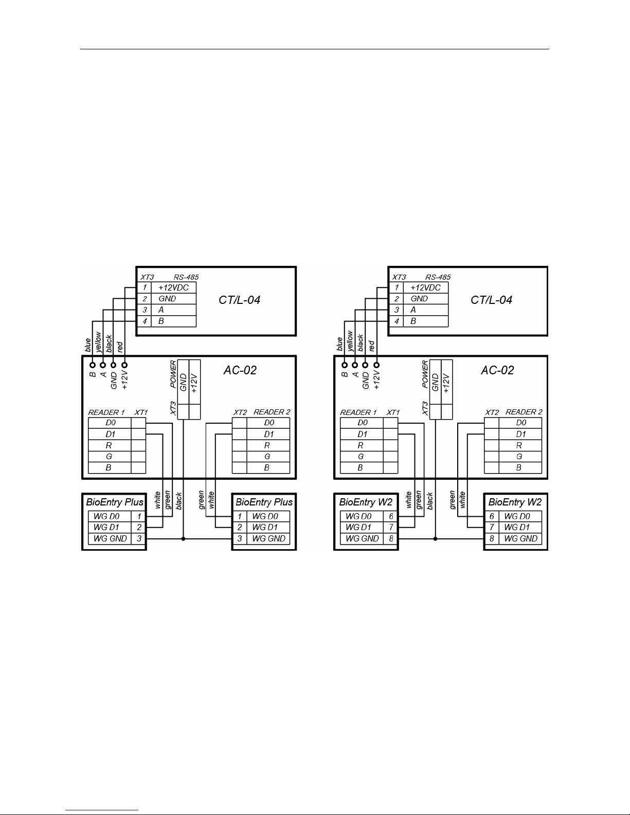
CT/L-04.2 Controller
Appendix 4. Instructions for connecting biometric readers
manufactured by Suprema
Biometric controllers Suprema BioEntry Plus and Suprema BioEntry W2 in the
PERCo-Web system can be used in two types of connection:
1. As a one-way lock controller. In this case, the OD is connected directly to the
supervisory output of the Suprema controller, communication with the Suprema
controller in the system is carried out via the Ethernet interface, therefore zoning
control for this OD in the system will not be supported.
2. As a fingerprint reader when controlling one of the directions of a double-sided lock
(turnstile). In this case, zoning control is supported; the OD is controlled by the outputs
of the CT/L-04.2 controller. The Suprema controller connects to the CT/L-04.2
controllers via the Wiegand interface via the AC-02 interface converter (connection
diagrams - Figure 20).
Figure 20. Connecting schemes for Suprema controllers to the controller
CT/L-04.2 via the AC-02 interface converter
49

User Manual
Appendix 5.
CT/L-04.2 Controller Web-interface.
User Manual
CONTENTS
1. WEB-INTERFACE OPPORTUNITIES ........................................................................51
2. CONNECTION TO WEB-INTERFACE OF THE CONTROLLER................................51
3. SETTING ....................................................................................................................52
3.1 Change of network setting of the controller ...........................................................52
3.2 Setting of the access password of the controller ...................................................53
3.3 Change the system time of the controller ..............................................................53
3.4 Choice of Settings of memory allocation ...............................................................54
4. CONFIGURATION......................................................................................................54
4.1 The choice of the controller configuration .............................................................54
4.2 Configuration of the Settings of the controller resources.......................................55
4.2.1 Operating devices.........................................................................................55
4.2.2 Physical contacts (inputs and outputs) .........................................................56
4.2.3 Readers ........................................................................................................57
4.2.4 The reading format of the card identifiers .....................................................58
4.2.5 Internal responses ........................................................................................59
5. CONTROL OF OPERATING DEVICE ........................................................................60
6. ACCESS CARDS .......................................................................................................61
6.1 Entering of the cards identifiers.............................................................................61
6.2 The list of stored cards ..........................................................................................63
6.3 Loading the identifiers from a file ..........................................................................65
7. EVENTS .....................................................................................................................65
8. STATUS .....................................................................................................................66
9. DIAGNOSTICS ...........................................................................................................67
50

CT/L-04.2 Controller Web-Interface
1. WEB-INTERFACE OPPORTUNITIES
Using Web-interface without installation of additional software allows performing following
steps for the controller and connected devices:
Change configurations, access password and time of built-in clocks of the controller.
Configure Settings of operational device, readers and other equipment’s of the
controller.
Set ACM for operation devices.
Record the access card numbers in the controller memory, assign them the rights for
arming or disarming.
Monitor event log of the controller and save them as a file.
Control the status of the controller and connected devices, monitor the event log.
Troubleshoot the controller, format the memory and update the embedded software.
Attention!
It is possible only with the Web-interface:
Select controller configuration and Settings of built-in memory (access
cards/events).
Add and delete the controllers of second level in configuration.
Add and delete optional readers in configuration.
Note:
Change of configurations via Web-interface of the controller is not available if the
controller is under control of network or local software of PERCo systems (you can
only monitor the configuration; operations are forbidden). The access to Webinterface is allowed if the software is configured to Allow Web-interface. It is
possible after stopping the operation of the software and stopping the server of
PERCo system.
2. CONNECTION TO WEB-INTERFACE OF THE CONTROLLER
Connection between the controller and the computer is performed via Ethernet interface
(IEEE 802.3). Make sure that the computer and the controller are on the same subnet
Ethernet. It may become necessary to change network settings of the computer, browser
settings and to check operation of the network. IP-address of the controller is specified in
the certificate and the controller board.
To connect the controller to Web-interface:
1. Open Web-browser (e.g. Internet Explorer).
Note:
Web-interface was tested with the Web-browsers: Microsoft IE version 10 or higher,
Google Chrome version 32 or higher, Mozilla Firefox version 32 or higher, Opera
version 30 or higher, Microsoft Edge and for MacOS Apple Safari 9 or higher. If you
use other browsers and outdated versions, malfunctions of the Web-interface can
appear.
2. Enter in the address bar IP-address of the controller and press the button Enter on the
keyboard. If necessary, enter the access password to the controller. By default, there
is no password. When entering the password, the content of the field User name
doesn’t matter.
51

User Manual
3. After that the main Web-page of the controller interface is opened. At the home page
are displayed the model, configuration, network settings of the controller and the
version of embedded software. Every time when you open the main page, current data
read from the controller are displayed there.
On the page, you can select following:
1. The title bar if he page contains PERCo trademark and buttons to select the language
of Web-interface. By clicking on the PERCo company logo you navigate to the main
page from other sections of Web-interface.
2. Sidebar of the Web-interface navigation. The panel has the following structure:
“Network”
“Password”
“Time”
“Settings”
“Memory usage”
“Template”
“Operation devices”
“Physical contacts”
“Readers”
“Card format”
“Configuration”
“Edit”
“Internal responses”
“Operating device control”
“Input”
“List”
“Access cards”
“Load from file”
“Events”
“Status”
“Diagnostic”
3. Working area of the page.
3. SETTING
3.1 Change of network setting of the controller
The controller has following configurations by default (they are specified in the certificate of
the device and on the labels on the controller):
MAC-address 00-25-0B-xx-xx-xx, where xx – is a number from 00 to FE;
52

CT/L-04.2 Controller Web-Interface
IP-address 10.x.x.x, where x – is a number from 0 to 254;
Subnet mask 255.0.0.0.
To change network settings of the controller (only in user mode, Sect. 5.3 of Operation
manual):
1. Click consistently in the Web-interface menu: Settings → Network. The page with
working area will be opened:
2. In the input fields IP-address:, Mask:, Gateway: the new values of network Settings
of the controller.
3. Click Save button. New network settings will be saved in the controller.
3.2 Setting of the access password of the controller
By default, access password of the controller is not specified. To change or set the new
password:
1. Click in the Web-interface menu: Settings → Password. The page with working
area will be opened:
2. In the New password: field enter the new password of the controller, in the
Confirm password: field enter the password again to confirm the correct input.
3. Click the Save button. The new password will be saved in the controller.
3.3 Change the system time of the controller
To change the time:
1. Click in the Web-interface menu: Settings → Time. The page with working area will
be opened:
2. In the input fields Change Date:, Change Time: change the set values.
3. If necessary, put tick Synchronize with PC: to synchronize the time and date of the
controller with the computer connected to the Web-interface.
4. Click the Save button.
53

User Manual
3.4 Choice of Settings of memory allocation
By default, the controller memory is allocated to store data up to 50 000 access cards and
up to 230 000 events. The user is able to change the memory allocation of the controller in
accordance with the controller configuration. Other options of memory allocation:
10 000 cards and 870 000 events,
20 000 cards and 710 000 events,
30 000 cards and 550 000 events,
40 000 cards and 390 000 events.
Note:
In software PERCo-Web are supported all these options, but their choice is only
available in the Web interface.
To change Settings on the memory allocation of the controller:
1. Click in the Web-interface menu: Settings → Memory usage. The page with
working area will be opened:
2. In dropdown list Memory resizing: select one of the variants of the memory
allocation.
3. Click the Save button.
4. CONFIGURATION
4.1 The choice of the controller configuration
Attention!
If you change the configuration, the previous configuration and at the internal
responses of all resources of the controller will be deleted. In the new template for
the resources of the controller is installed default configuration. The list of
downloaded access cards, related user information, rights and parameters of
access remain the same.
To change the configuration of the controller:
1. Click in the Web-interface menu: Settings → Template. The page with working area
will be opened:
54
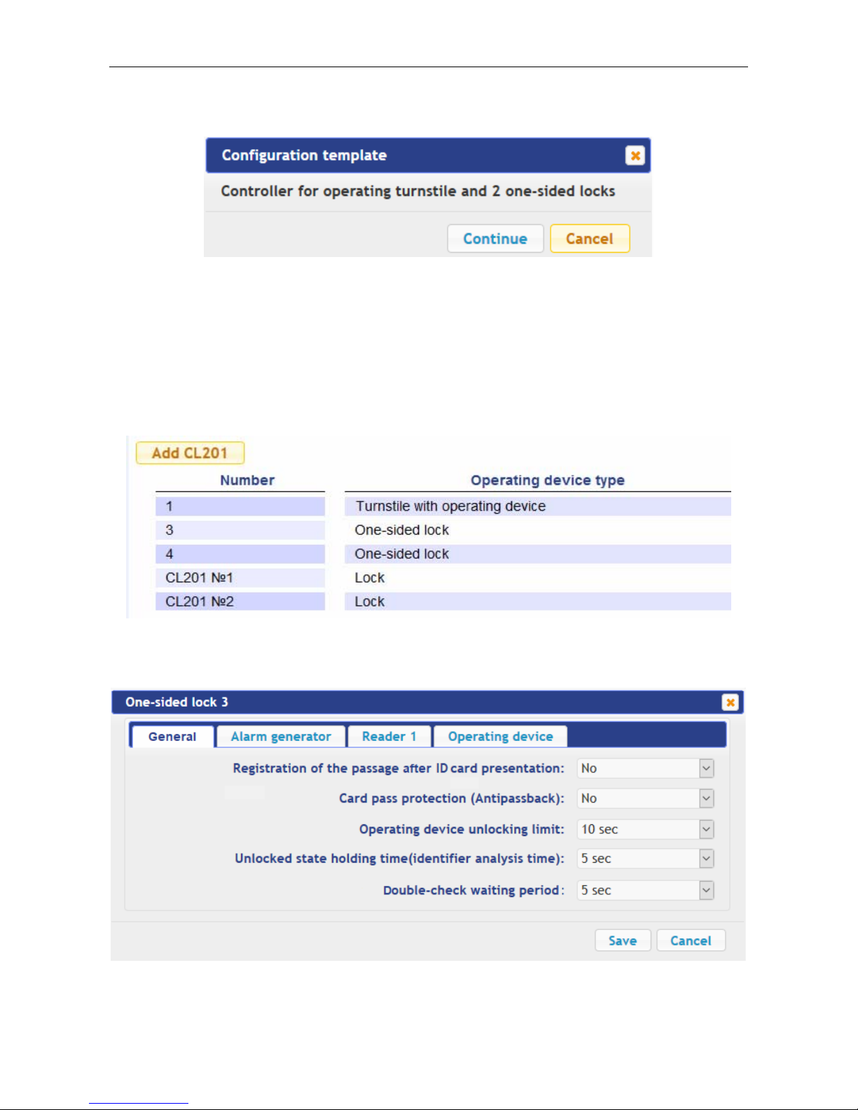
CT/L-04.2 Controller Web-Interface
2. The controller configurations are presented in dropdown list of working area of the
page. The window Configuration template should be opened where selected
configuration is specified:
3. In the opened window click Continue. The controller configuration will be changed.
Change the configuration template can take 30 seconds.
4.2 Configuration of the Settings of the controller resources
4.2.1 Operating devices
To configure Settings of the controller resources to control OD:
1. Click consistently in the Web-interface menu: Configuration → Edit → Operating
devices. The page with working area will be opened:
2. To change Settings of the OD, click in the working area of the page on a line with his
name. To add to the list, the new ODs with the controllers of the second level (CL-201),
click the Add CL201 button. The window with the OD name will appear:
3. In the opened window on the tabs General, Alarm generator, Reader (number),
Operating device make the necessary changes of the Settings for corresponding
resources.
55

User Manual
Note:
For the resource Reader (number), the parameter Card rights number: indicates
the number of the set of card rights used for passing with this reader. Individually for
each card can be configured 12 different sets of rights.
4. Click the Save button. The window will be closed, changed Settings will be passed to
the controller, the added OD with the controller CL-201 are included in the controller
configuration.
5. To remove the OD from the configuration with the controller CL-201, in the window with
this OD click the button Delete. The OD will be deleted.
6. To exit the window with the name of the OD without saving the changes, click the
Cancel button or the Close button .
4.2.2 Physical contacts (inputs and outputs)
To configure the Settings of the controller inputs and outputs:
1. Click consistently in the Web-interface menu: Configuration → Edit → Physical
contacts. The page with working area will be opened:
The page lists all the controller inputs and outputs.
When you select the template (Clause 4.1) the inputs and outputs that are involved in
the control of the OD of this template, corresponding functions are stated (for inputs –
PASS / RC, for outputs – control of OD / indication of the RC-panel) and specify the
number and direction of the OD which the physical contact is attached. Inputs and
outputs that are not selected in the template, the value is Not specified. These inputs
and outputs are available for the task (and changes in the future) of its functions.
56

CT/L-04.2 Controller Web-Interface
Depending on the template, the inputs 5 and 6 can have function Alarm lines. The
functions set for the inputs / outputs cannot be changed (it is possible to change only
normal state and for inputs the time duration of denouncing). The alarm lines function
can be changed with the tamper to the function Alarm lines.
2. Click in the working area of the page on the line with the name of the input (output).
The window with the physical contact will be opened:
3. In the opened window make necessary changes of the Settings:
selector Normal state: defines the normal state of the contact – it is opened or
closed for inputs or Energized and Not energized for outputs;
selector Function: sets the function of the contact.
4. Click the Save button. The window with the physical contact name will be closed, the
changed Settings of inputs (outputs) will be passed to the controller.
5. To exit from the window of physical contact without saving changes, click the button
Cancel. Also, it is possible to close the window using the Close button .
4.2.3 Readers
In all controller configurations for each direction of every OD is determined one reader or
one infrared-panel (hereafter – reader). Optionally, it is possible to add in the configuration
optional readers for the directions of passage through the OD. For one direction can be
installed two or three readers working in parallel. It can be useful, for example, when
connecting the card capture reader, organizing the vehicle checkpoint to accommodate the
readers at different levels (for cars and trucks), etc. Totally, to the controller can be
connected up to 8 readers.
Note:
When you add optional readers, they have the configuration similar to the card
capture readers attached to the same directions of the OD. In this regard, added
readers are not appeared in network and local software of PERCo-Web system.
To configure the Settings of the reader:
1. Click consistently in the Web-interface menu: Configuration → Edit → Readers. The
page with working area will be opened:
57

User Manual
2. Click in the working area of the page on the line with the name of necessary reader, to
add the reader in the list click the Add button. The window Reader (number) will be
opened:
3. In the opened window make the necessary changes of the Settings:
selector Number: specifies the number of added reader.
selector Operating device: specifies the number of the OD to which the reader is
attached.
selector Direction: sets the direction of the OD to which the reader is attached.
4. Click the Save button. The window Reader (number) will be closed, changed Settings
will be passed to the controller, added reader with assigned number will be added in the
list.
5. To remove the reader from the configuration, click the Delete button. Window Reader
(number) will be closed, the reader will be removed from the list.
6. To exit from the window Reader (number) without saving changes, click the button
Cancel. Also, it is possible to close the window using the Close button
.
4.2.4 The reading format of the card identifiers
Attention!
Change of this parameter when you have already entered the access control
cards, results in the passage on these cards will be impossible.
When connecting to the controller working under software of PERCo systems,
the current formant may not be shown (nothing is selected from the formats). In
this case to change the reading format of card identifiers is PROHIBITED.
To select the reading format of card identifiers:
1. Click consistently in the Web-interface menu: Configuration → Edit → Card format.
The page with working area will be opened:
2. Using the drop-down list Card reader operating mode: select one of offered formats
and click the Save button.
58
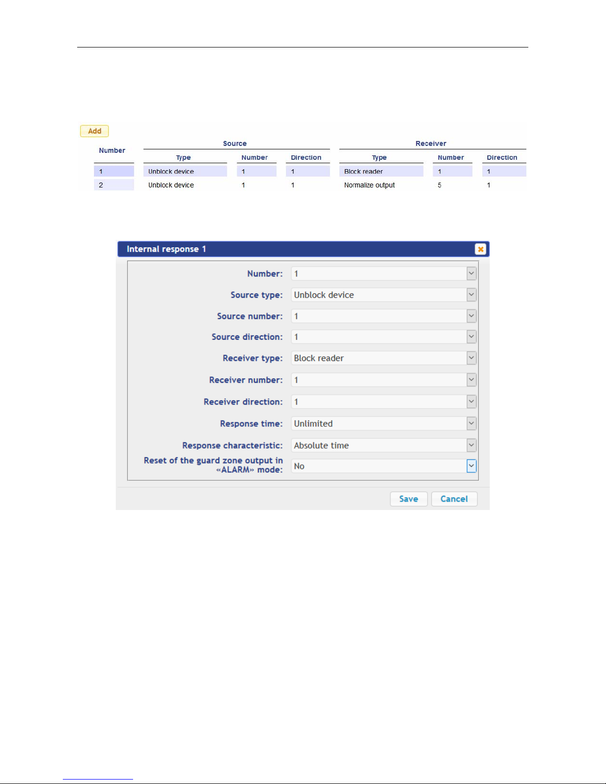
CT/L-04.2 Controller Web-Interface
4.2.5 Internal responses
To set internal responses of the controller:
1. Click consistently in the Web-interface menu: Configuration → Edit → Internal
responses. The page with working area will be opened:
2. To add the new response, click the Add button, to change the Settings of internal
response or delete it, click in the working area of the page on the line with the
response name. The window Internal response (number) will be opened:
3. In the opened window make the necessary changes of the Settings:
Selector Number: sets the number of response (from 1 to 40).
Selector Source type: specifies the launch condition of the controller response.
Selector Source number: (Receiver number:) and Source direction: (Receiver
direction:) determine numbers and directions of corresponding resources of the
controller which are sources (receivers) of the response.
Selector Receiver type: specifies the controller response under condition of the
responses launch.
Selector Response time: and Response characteristics: set corresponding
Settings of the response.
4. Click the Save button. The window Internal response (number) will be closed, the
changed Settings will be passed to the controller.
59
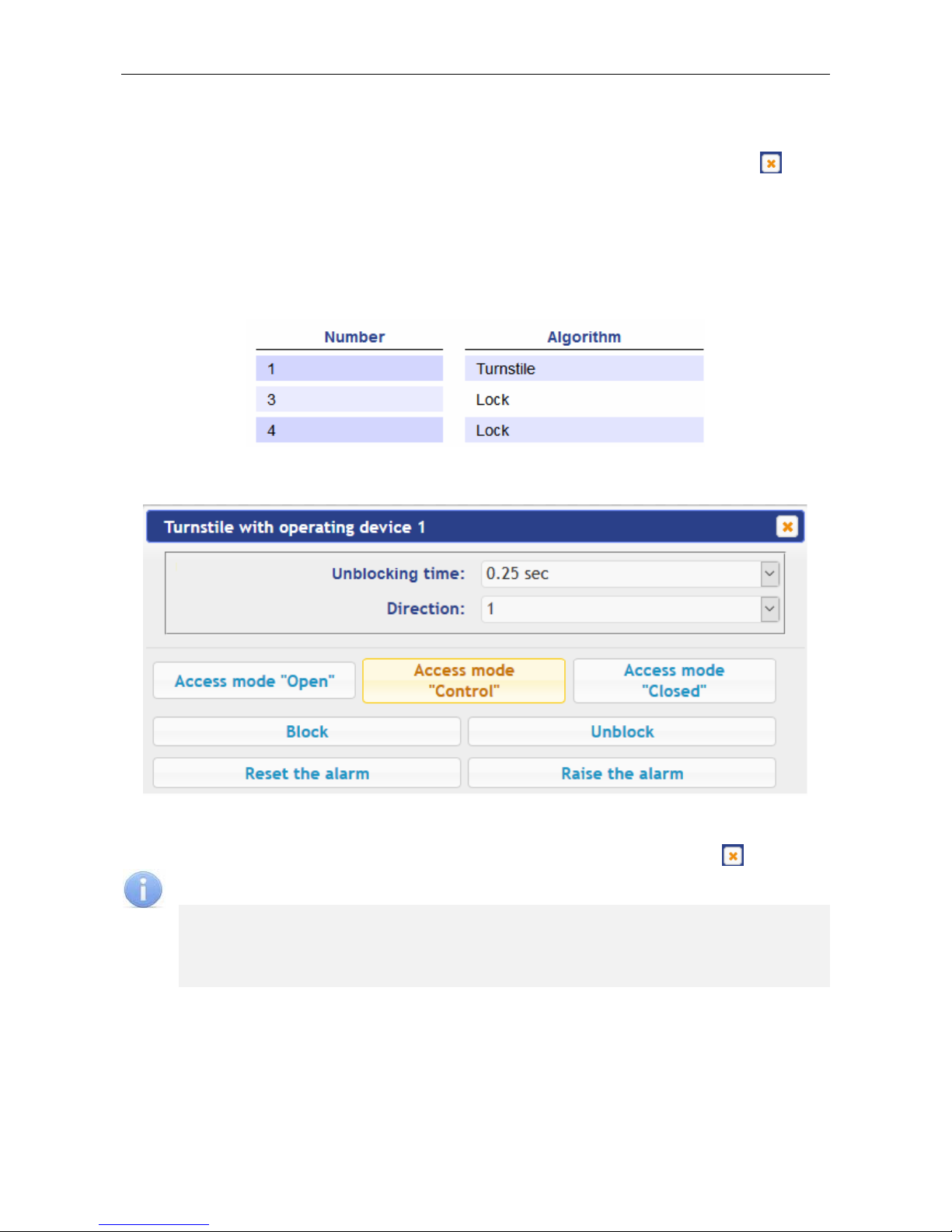
User Manual
5. To remove the response from the list, click the Delete button. The window Internal
response (number) will be closed, the internal response will be deleted.
6. To exit the window Internal response (number) without saving changes, click the
Cancel button. Also, it is possible to close the window using the Close button .
5. CONTROL OF OPERATING DEVICE
To control the operating device and change the operation mode in the direction with
associated reader, make following:
1. Click in the Web-interface menu: Operating device control. The page with working
area will be opened:
2. Click in the working area of the page on the line with OD, to which it is necessary to
issue the control command. The control window with selected OD will be opened:
3. Using the buttons at the bottom part of the window, give the necessary command. The
control window will be closed; the command will be passed to the controller. To close
the window without submitting command is possible with the Close button .
Note:
When arming, the direction of the OD associated with the reader is set, you
select it in the dropdown Direction list.
When you unlock the OD will be unlocked for the time chosen in the drop-down
list Unlock time.
60

CT/L-04.2 Controller Web-Interface
6. ACCESS CARDS
6.1 Entering of the cards identifiers
The main list of the cards is the list of identifiers of access cards brought into controller
memory. This list is accessed through the OD.
The emergency list of the cards is an optional list of identifiers of access cards that are
loaded to the controllers of the second level of the series CL-201. This list is accessed
through the operation device connected to this controller in case of decoupling with the
controller of first level.
Note:
Emergency list of cards in the controller CT/L-04.2 is not saved, after loading his
second viewing in the Web-interface becomes unavailable.
To enter the card identifiers:
1. Click consistently in the Web-interface menu: Access cards → Enter. The page with
working area will be opened:
2. If necessary, use the dropdown list in the heading of the Number type column, select
the format to display the cards identifiers.
Note:
The display format is not the format of reading of the card identifiers (set in the
Configuration section, Clause 4.2.4), when you change the display format, the
format of reading does not change.
3. Entering of the card identifiers from the reader
:
In the working area of the page click the Switch on card reader input button.
Present your card to one of the readers included in the controller configuration. The
card identifier will appear in the working area of the page. Also, you will see the
buttons Save and Load to emergency list.
If necessary, similarly add other cards.
61

User Manual
In the working area of the page click the Switch off card reader input button.
4. Entering of the card identifiers manually:
In the working area of the page click the Manual input button. The window Card
input will be opened:
In the Card number: field enter the card identifier. Click the Save button. The
window Card input is closed; the card identifier appears in the working area of the
page.
If necessary, similarly, add the other cards.
5. To transfer the entered card identifiers to the controller, click the Save button in the
working area of the page. The identifiers will be transferred to the main list of the cards
in section List.
Attention!
When you enter the card identifiers in the list of the controller, by default they are
granted rights of access over all ODs connected to the controller (all 12 sets of rights
for each card have the status Unblocked), Clause 6.2.
6. To save entered identifiers in the emergency card list of the second level controller:
Click the Load to emergency list button. The window Loading to emergency list
will be opened:
In the opened window with dropdown list Selected: put ticks near the controllers of
the second level, which emergency lists you want to transfer the entered cards.
Click the Load button. The window Loading to emergency list will be closed,
entered identifiers will be transferred to the marked controllers.
62

CT/L-04.2 Controller Web-Interface
6.2 The list of stored cards
To work with the list of the cards stored previously in the controller’s memory:
1. Click consistently in the Web-interface menu: Access cards → List. The page with
working area will be opened:
2. If necessary, use the dropdown list in the heading of the Number column, select the
format to display the cards identifiers.
Note:
The display format is not the format of reading of the card identifiers (set in the
Configuration section, Clause 4.2.4), when you change the display format, the
format of reading does not change.
3. To save the cards to a file, click the Save file button. The cards will be saved in the file
cards.bin, which can be used as a backup card list.
4. To remove all the cards from the controller memory, click the Clear log button.
5. To change the Settings, select one of the cards in the working area of the page. The
window of the identifier of the selected card opens:
63

User Manual
6. If necessary, in the opened window on the Essential tab change the card Settings.
7. Go to the Access rights tab. It is possible to set access rights for this card. To do this,
select the number of the set using the drop-down list Card rights number and
configure the Settings:
Attention!
Each card has 12 sets of access rights which in the section Configuration are
assigned to the readers of the ODs (Clause 4.2.1). When you enter the cards in the
controller list, by default they are granted the access rights over all connected ODs
to the controller (all 12 sets for each card have the status Unblocked). To set the
card only specific sets of access rights is necessary in these sets of rights to keep
the status Unblocked, but in the other sets to put the status Blocked.
8. To delete the card, click the Delete button at the bottom part of the window.
9. To save changed Settings of the card, click the Save button. The window will be
closed, changed Settings will be passed to the controller.
The Settings of the set of access rights correspond to similar Settings in network
software of PERCo systems.
Attention!
Setting of Settings of time access criteria via the controller is possible only in
network software of PERCo systems. In the Web-interface is only possible to
change the time criterion (time zone, weekly schedule, flexible daily schedule,
flexible weekly schedule) and transition from one set of time Settings to another set
by changing his number. The number of time criterion corresponds to order number
of the set of Settings of time criterion in the network software.
64

CT/L-04.2 Controller Web-Interface
6.3 Loading the identifiers from a file
Attention!
When loading the list of cards from the file to the controller, previously loaded cards
are deleted automatically from the controller memory.
The list of the cards can be loaded only from the file cards.bin, created via Webinterface of the controller earlier. To download the numbers of the card from a text file:
1. Click consistently in the Web-interface menu: Access cards → Load from file. The
page with working area will be opened:
2. Click the Browse… button. In the opened window of the Explorer specify location and
name of the file with the card list and click the Open button. The explorer window will
be closed; the file name will be indicated in the field near the Browse… button.
3. Click the Load button. The window Progress will be opened containing information
about the boot process.
7. EVENTS
To view the event log of the registration of the controller:
1. Click in the Web-interface menu: Events. The page with working area will be opened:
2. By default, all events stored in the controller memory are displayed, by 20 events on
the page. To move through the pages of the event, use the buttons located in the
lower part of the working area. The events in the working area of the page are
displayed in reverse chronological order.
65

User Manual
3. There is possibility of selection in the report of events by categories and time. To do
this, click the Filter button, the window Filter will be opened:
4. In the dropdown list Selected categories: [number] put ticks the event categories
which should be reported. Following categories of events are available:
ID Card access
Guard zone status change
Guard zone resource state change
Change input/output state change
Access without ID Card
Functioning
5. Use the fields Range beginning point and Range end point to set the period of the
report.
6. Click the Apply button to apply the filter, click the Cancel button to cancel any made
changes. The window Filter closes, the report will display the events in accordance
with the filter settings.
7. To save the events to a file, click the Save button at the bottom part of working area of
the page. The events will be saved in the file events.txt.
8. To delete all events from the controller memory, click the Clear button at the bottom
part of working area of the page.
8. STATUS
To view the controller status and status of all his resources click in the Web-interface
menu Status. The page with working area will be opened:
66

CT/L-04.2 Controller Web-Interface
9. DIAGNOSTICS
For diagnostics and maintenance of the controller:
1. Click in the Web-interface menu: Diagnostic. The page with working area will be
opened:
2. To start testing the status of the controller hardware click the Start button in the line
Diagnostics (50 min):. In the confirmation window click OK.
Attention!
When testing the controller, the event log is automatically cleared.
3. For diagnostic purposes of the controller with the previous formatting, click the Start
button in the line Diagnostics formatting (15 min):.
4. To start formatting the internal memory of the controller, click the Start button in the
line Format (2 min):. In the confirmation window click OK.
Attention!
When formatting the controller memory, the information about configuration, access
cards, time and area zones, controller password and events in the event log is
automatically cleared.
5. To update the controller software (firmware), indicate the location of the software file
using the Browse button and click the Update button.
67

PERCo
Polytechnicheskaya str., 4, block 2
194021, Saint Petersburg
Russia
Tel: +7 812 247 04 64
E-mail: export@perco.com
support@perco.com
www.perco.com

www.perco.com
 Loading...