

Page 1
Per Brohall
S-68101 Kristinehamn 1 . Sweden
www.jonesboatyard.co.uk
Page 2
.
-
Foreword: this handbook is for AD21 engine models (years 70/72)
The object of this handbook is to provide Albin 25 owners with a concise manual on
how the boat should be used and maintained. Instructions regarding the Albin Engine
Type AD
-
21 can be found in a separate instruction book. Instructions for running in
and manouvering are repeated here. Where data in this book differs from the engine
instruction book, the instructions in this book should be followed.
Even a boat
so
well equipped as the Albin 25 may, after delivery and launching, re
-
quire some adjustments, e.g. trimming of rig; minor engine adjustments; tightening
of
screws, nuts and hose clips; and repairs to minor damage sustained during ship
-
ment. The manufacturer will naturally stand by his guarantee, bu t the low price of
Albin 25 is calculated on the basis that a normally handy owner can himself take care
of
maintenance items such as mentioned above. This means that the manufacturer's
resources can be used more effectively fo r guarantee repairs where skilled person
-
nel are really required.
If
there are any problems which are not discussed in this handbook don't hesitate to
write to Albin Marin AB for advice.
We wish you a happy time with the Albin 25.
2
www.jonesboatyard.co.uk
Page 3
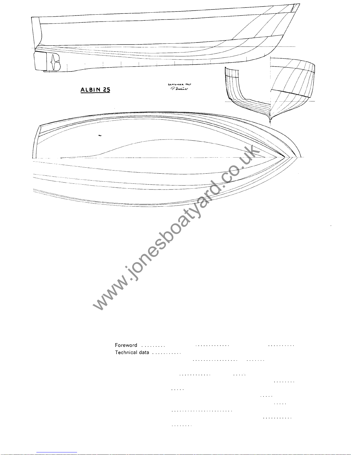
Fig.
1.
The
lines.
Per
BrohaII:
The
ALBIN
25
handbook
CONTENTS
...........
..............
2
.......................................... 3
Performance and characteristics
...
...........
5
Influence
of
the propeller on manoeuvring
............................. 7
First launching
..........
Engine installation and maintenance
..........................
Interior and equipment
.........................................
Winter storage and spring commissioning
......................
Tie her up right
......
Sails on Albin 25.
...................................... .
29
32
More general advice
.
.
........
..................
10
10
15
Glassfibre and maintenance
.............................
........
23
...
,,
25
.......................
26
......................................
www.jonesboatyard.co.uk
Page 4
Technical data
The
motorboat
ALBIN
25
Designer Per Brohall
.........
7.6 m 25ft.0in.
6.75 m 22 ft. 2 in.
Beam 2.6 m
8
ft. 6 in.
0.7 m 2 ft. 4 in.
Height from mast support to deepest part of keel
....
2.75 m
9
ft.
Height from mast support to waterline
..............
2.1 m 7 ft.
Displacement (empty boa
.....
1.600kilos, 1.6tons
Maximum speed, about
...
8
knots
Economical speed, about
.........................
7 knots
Sound level at helm
...............................
74 db
..................................
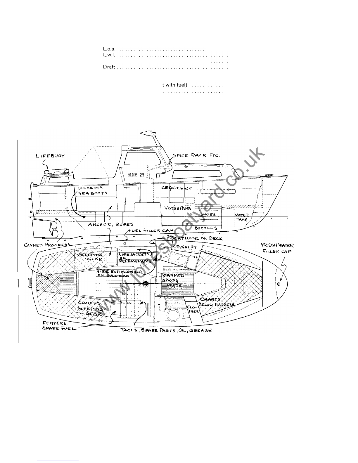
Fig.
2.
Accomodation
and
stowage plan (example).
Engine installation
Engine, Albin 4-stroke diesel type AD-21 with single lever teleflex control of engine
Maximum revs
..................................
2300-2400 rpm
Engine power at maximum rpm
....................
Economical r pm about
............................
Idling speed about
...............................
Maximum idling time with gears i n neutral
..........
Fuel consumptionateconomical rpm
...............
revs and gearbox.
22horsepowerSAE
17
horsepower
DIN
2000 rpm
650 rpm
30 min.
2.2 I/h
0.55
US.
gal./h
0.45 Imp. gal./h
3
www.jonesboatyard.co.uk
Page 5
Oil quantity when changing t o new oil
..............
Oil quality
......................................
Oil viscosity
....................................
Oil pressure (with warm engine).
..................
Cooling water temperature
....................
Direction of engine rotation (looking forward)
........
Reduction rear ratio
...
.......................
Propeller shaft of stainless acid proof steel with two
inner sealing rings and a rubber mounted outer bear
-
ingof water lubricated fibre.
Shaft diametre
..................................
Rotating direction of the propeller seenlooking forward
Propeller
3
bladed
............................
Alternator
.......
Lighting battery capacity
..........................
Starting battery capacity
.............
3-3.5 litres
0.68-0.75 Imp. gal.
0.8-0.9
US.
gal.
Service DM or DH oil for diesel engines
SAE
30
2--3 kp/cm2
28-43Ib/sq. in.
70-85°C
anti
-
clockwise
2.04:
1
25 mm
anti
-
clockwise
16 1/2
x
1
2“
12 volts
490watts
57-60 Ah
57-60
Ah
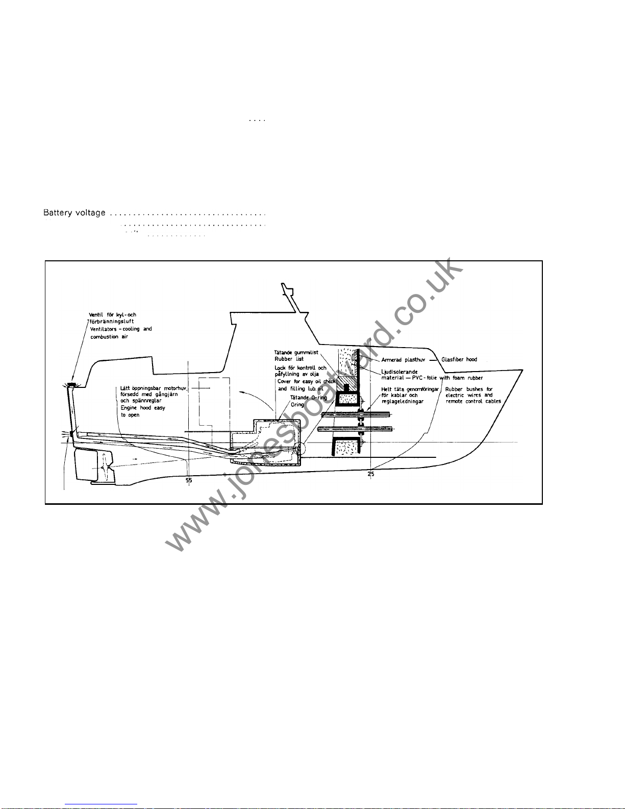
Fig. 3. Air ducts and sound-proofing fo r the engine
.
Glassfibre lamination
The thickness of the
hull
is 6 mm in t he topsides and 8 mm below the waterline. The
hull is strengthened with glassfibre angles
-
stringers and frames -and by floors,
engine bed and air ducts laminated into the hull.
Horizontal areas of
deck and cabin top
are sandwich construction with a core material
of Divinycell (PVC cellular plastic).The top laminate is 3.5 mm (5/32”) thick, the Divi-
nycell 15 mm
(5/8”)
and the inner laminate 2.5 mm
(1 /8"")
Certain areas have a pres
sure proof filler of polyester and Vermiculite (a mineral product). Moulded into the
deck are conduits for the electrical wiring and wooden blocks to take the various
through bolts. The deck is bolted and laminated to the flange o n the hull and the joint
is covered with a toe rail of PV C plastic.
Engine cover
of glassfibre is sound insulated with 30 mm sound deadening foam. The
engine bed has sealed bushings for fuel, water and exhaust lines and rubber bushings
for electrical wires and control cables. The engine room is completely sealed off from
the hull. Leaking oil cannot spread and smell throughout the bilges.
Windscreen
and
side windows
are made of hardened glass. Fore and aft cabin curved
windows ar e o f acryllic glass.
The
rudder
is made of glassfibre. The
rudder stock
is 25 mmacid proof stainless steel
and i s glanded with a water lubricated fibre bushing. The wheel
steering gear
and
flexible cable are b y Teleflex. The flexible cable works
a
rudder arm on the rudder
4
www.jonesboatyard.co.uk
Page 6
stock. The wheel turns two full revolutions from side to side giving a rudder angle of
35
"
each side. If the flexible cable is loosened from the rudder,arm a spare tiller can
be mounted directly into the rudder arm.
Fuel
tank is made of Argon welded stainless steel plate with a capacity of 75 litres
(16.5 Imp. gal., 20
Us.
gal.).
Water tank is made of Polithene with a capacity of 65 litres (14 Imp. gal.,
17
US.
gal.).
Performance and characteristics
Stability
If the power and length
of
a motorboat are increased the speed is increased, but if
the weight (displacement) is increased, there is a
loss
of speed. The Albin 25 has
been designed around its engine to produce the most efficient boat, obtaining the
best speed with available power. This means that the boat must b e light. Therefore
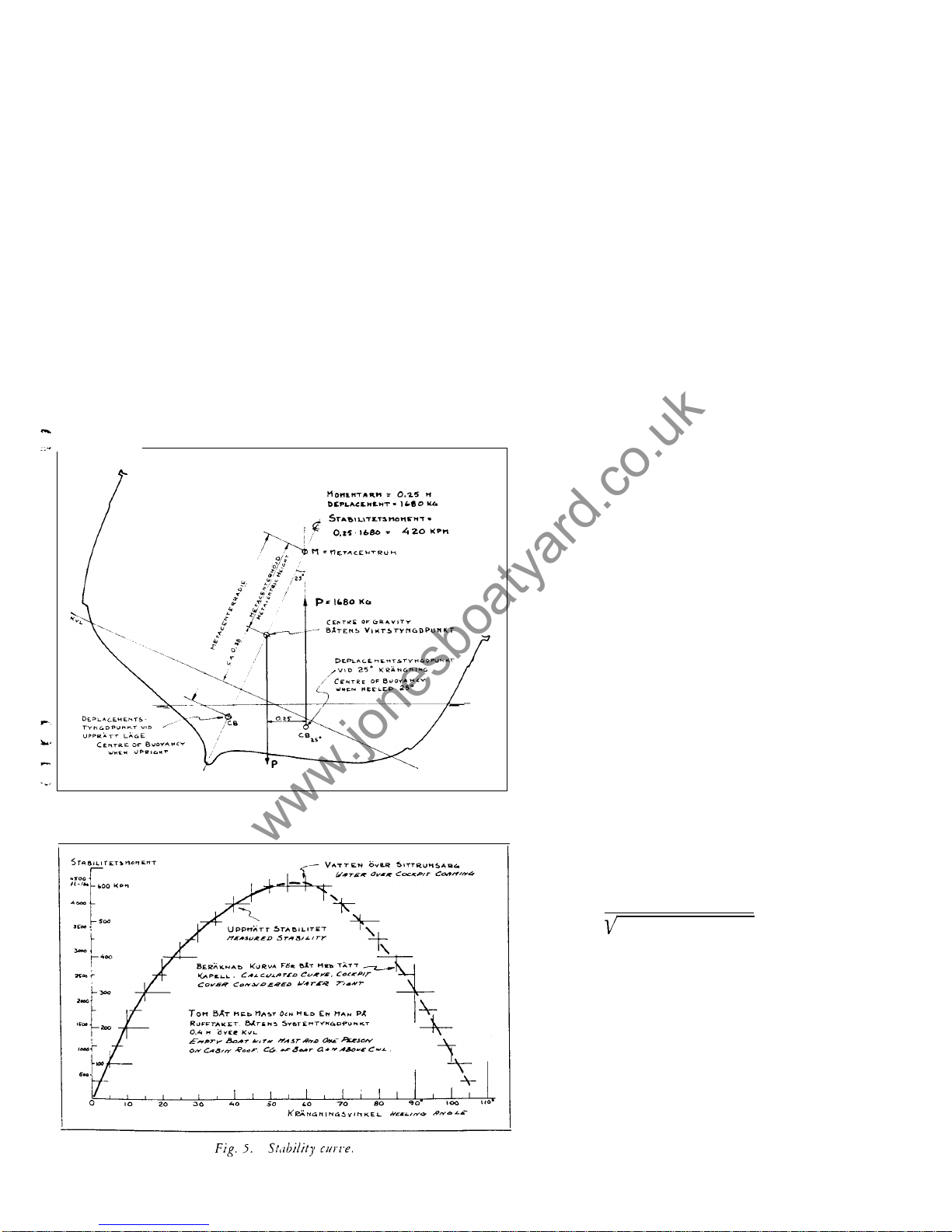
the necessary stability is achieved by means of a suitable hull shape
-
giving form
stability. Fig. 4 shows just how the force of gravity
(P)
works from the centre of
gravity and how in a heeled position a similar force works vertically up from the
centre of displacement. If we multiply displacement
(P)
(in this case 1680 kilograms)
times the length
of
the moment arm (distance 0.25 metre between the two forces) we
get the stability moment which is the
"
power"which will bring the boat back t o an
upright position. Heeling an Albin 25 up to 50
degrees (empty boat with mast and boom and
one person on the cabin top) the accompa-
Fig.
4.
Section showing stability moment.
nying stability curve was measured a (fig. 5).
For heeling angles larger than 50 degrees the
stability moment has been calculated as
shown. As a comparison the sailboat Vega
has about twice as large a stability moment
up to heeling angles of 50degrees. A normally
loaded Albin 25 weighs more than t he test
boat and also has a lower center of gravity.
Because of this the loaded boat gains even
better stability than the curve shows.
It
shows
that the Albin 25 is as good as uncapsizable
and that yo u can use rig and sail without any
risk of capsizing. I t also shows that ballast is
not necessary from a stability point of view.
Ballast decreases speed through increased
weight and if the ballast i s put deep into the
boat
it
can also give a less comfortable move
-
ment to the boat.
Period
of
roll
The results of such good stability give the
Albin 25 a comparatively quick natural period
of roll (time of swing from one side to the
other and back).
A
longer period of roll gives
a more comfortable athwarthship movement
in a seaway. The formula for calculating the
period of roll
(t)
is:
t=
1.108xradius of inertia
metacentric height
Radius of inertia means the distance from the
axis of rotation to a theoretical point where
the mass o f the boat is concentrated when
rolling around this axis. The radius of inertia
can be considered about the same as the
length of a pendulum. The meaning of the
meta
-
centric height is shown in fig. 4 which
also shows that this height is a measure of
stability. An increase
or
a
decrease of the
meta
-
centric height gives an increase or de
crease of stability. Seeminglyitis possible to
lengthen t he period of rollthrough decreasing
the meta
-
centric height (the same as raising
the center of gravity
of
the boat which i s the
5
www.jonesboatyard.co.uk
Page 7

same as decreased stability) or through increasing the radius of inertia (putting
weights farther from the axis of rotation). Here are examples ho w these factors can
be used t o effectively dampen
a
boat's movements in a seaway:
1.
On sailing yachts you can hoist a heavy anchor up the rigging (decreasing metacentric height and increasing radius of inertia without increasing weight).
2. On an Atlantic passenger ship the motion in
a
seaway was unsuitable for pas
-
sengers. The cure was 200 tons of stone on top of the upper deck.
The same effect has been measured on the Albin 25. The period of roll was measured
with an empty boat, with one man (85 kilograms) positioned in different places. The
following times were measured:
low position
...............................
2.05 seconds
at the helmsmans place
.....................
2.15 seconds
on top of the cabin
.........................
2.40 seconds (an increase of 25%)
Ballast a n d movements in a seaway
The above technical discussion on the period of roll has been given to giveaback
ground to the following advice regarding ballast or no ballast. Several owners of the
Albin 25 think that the boat will have a calmer motion if ballast is used and many more
ask questions regarding ballast. One publication has advised that a ballast of 500
kilos b e used down in the bilges. With conflicting advice it seems advisablet o discuss
this question more thoroughtly.The reasons usually given as to why'ballast should be
used is the desire to obtain better stability and calmer motion in a seaway. Here we
have two conditions contrary to each other and where i t will be necessary to choose
a suitable compromise.
Increased stability
is not necessary. This is clearly shown in the stability curve fig. 5.
When the weight of the boat is increased with equipment, provisions etc., the stability
is increased and much more
so
if everything is stowed deep down in the boat.
Calmer movements in a seaway:
The main part of the discomfort experienced in a
motorboat in a seaway is caused by the athwarthship movements
-
the rolling.
There is the unhappy case where the period of the wave train is the same as the
boats natural period of roll and the motion of the boat therefore is increased. An
alteration o f the course may change this. Each boat and each size of boat has a type
of sea which is especially uncomfortable.
Albin 25 has been designed for comfortable motion in normal use, loaded with a full
crew and all necessary equipment. The hull form gives a very comfortable movement
in a headsea. In certain types of seaways and also in open anchorages the boat can
develop relatively quick, uncomfortable athwarthship movements because of it s form
stability. I n open waters with a short and uncomfortable sea, calmer athwarthship
movements ca n be h ad through using:
1.
Sails.
A mast in itself is enough t o increase the roll period and give a calmer
motion. With sails and a good wind the movement is considerably dampened.
2.
Mechanical stabilization.
There are several different systems, as a rule they are
too expensive.
3.
Lengthening the period ofroll.
Through his ow n efforts the owner can increase
the period of
roll
by stowing all equipment and cargo (provisions, drink, etc.) as
high u p and as far out t o the sides as possible. A dinghy and anchor stored on
the deck helps f o r instance t o give a better motion. An increase in the total weight
of the boat increases th e radius of inertia i f the increase of weight does not ride
on the axis of rotation.
To
use ballast is not advised i f it is possible through other efforts to improve the
movement of the boat t o satisfy your personal taste. If ballast is used to dampen the
movements i t should be stowed high up and as far out to the sides as possible. Such
ballast must be fastened thoroughly
so
as not to come adrift i n a seaway. If ballast
is
placed deep down, the meta-centric height is increased (which shortens the period
of roll). The radius of inertia is increased considerably i f ballast i s placed high up and
far out to the sides. It is a completely faulty use of ballast to place it far down hoping
for better motion, and the effect may be only 25% of what the right position will give.
Don't forget that every increase in weight also decreases the speed, increasing fuel
consumption. For instance
500
kilograms of ballast results in a reduction of maximum
speed by about 3/4 of a knot (10%) and a reduction of cruising speed by
about 1/3 of a
knot (5%).
Fuel consumption and speed
Fig.6shows how much power must be delivered to the propeller to give the Albin 25
a certain speed. The power shown is about equal to the
DIN
power minus 5% to 10%
(losses in alternator, gearbox, shafts, bearings, etc). The efficiency of the propeller at
around
58%
is good. Itfollows that the thrust is a little more than half of the available
6
www.jonesboatyard.co.uk
Page 8
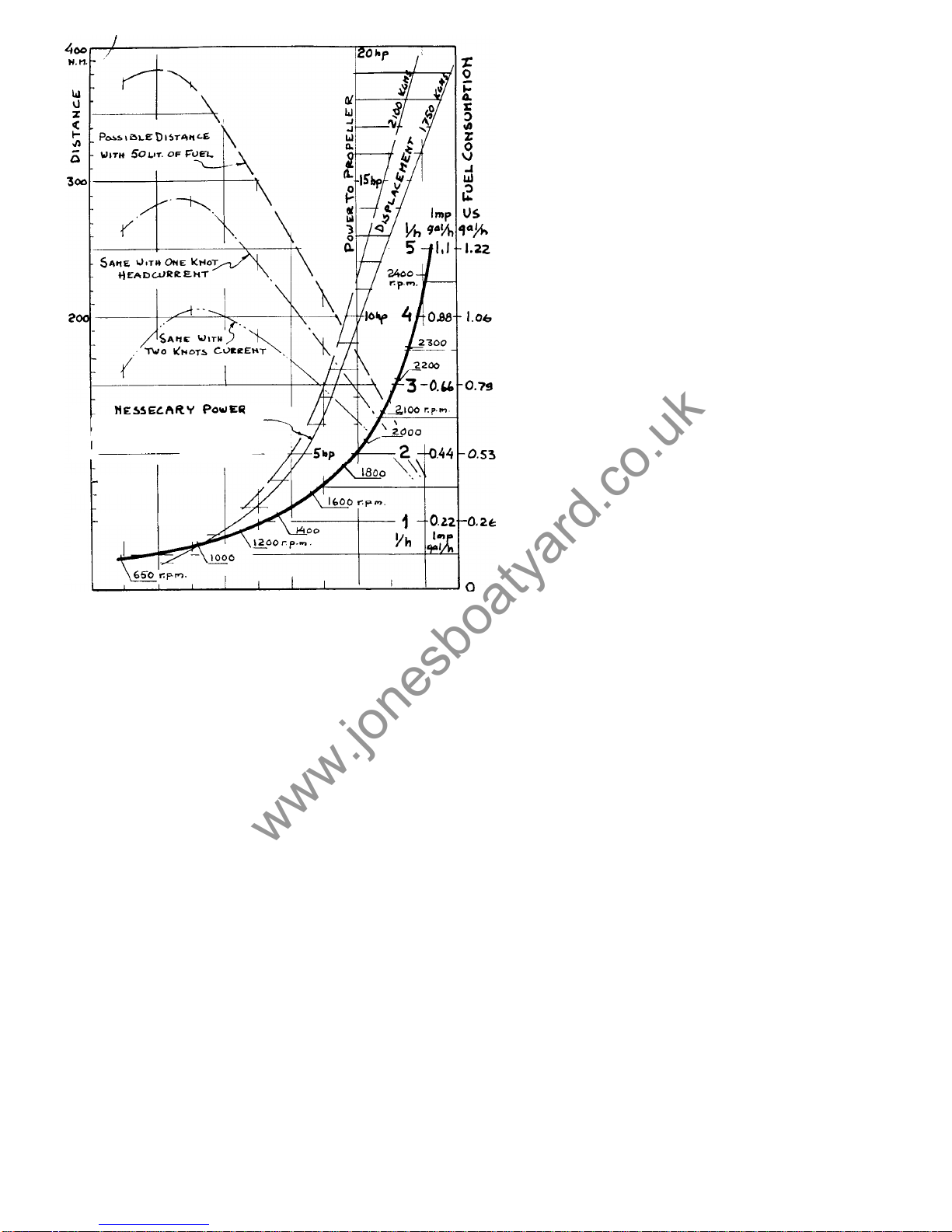
power. The curves for displacements
of
1750
kilograms and 2100 kilograms give an idea of
what an increase in weight means. That an in
-
crease
of
power is needed with increased
speed is still more clearly shown
-
a
speed
of
8
knots requires
12 to 15 times as much
power as for
4
knots! At low speed the resist
-
ance of the boat is mainly friction (about
95%
of the total resistance) at 8 knots the frictional
resistance is about 55% of the total resist
-
ance - the
rest is form resistance - wave
resistance plus a
few percent air resistance.
It is important to have a clean bottom with the
least possible frictional resistance.
Fuel
consumption
at different revs and speeds
also appear in fig.
6.
These values are the re
-
sults
of
many measurements and can be con-
by the tachometer
of
the
boat
can at full revs
sidered correct to within 5%.The rpm shown
show up
to 150 rpm too little and sometimes
up to 50 rpm too much. At cruising revs the
fault is considerably smaller - about
60%
of
the error at full rpm. At idling rpm the fault is
very small. The speeds shown are for calm
weather without any sea. Also in the diagram
there are 3 curves showing the largest possible distance covered with 50 litres of fuel.
These show how economical it is to use a low
rpm if it is desired to go as far as possible
with a certain quantity of fuel. The curves
shown for one or two knots head current can
also be used if the speed is diminished by
headwinds and headseas. They show how the
most economical rpm increases as head cur
-
rent increases.
3
KNOTS
4
5
b
7
a
Do
not trust a speed log which has not been
tested and calibrated. It is not unusual that
the log can show more than one knot error.
.
FOR
DIFFERENT SPEEDS
AND
DISPLACEMENTS
I00
Fig.
6.
Fuel
consumption
and
resistance.
Influence
of
the
propeller on
manoeuvring
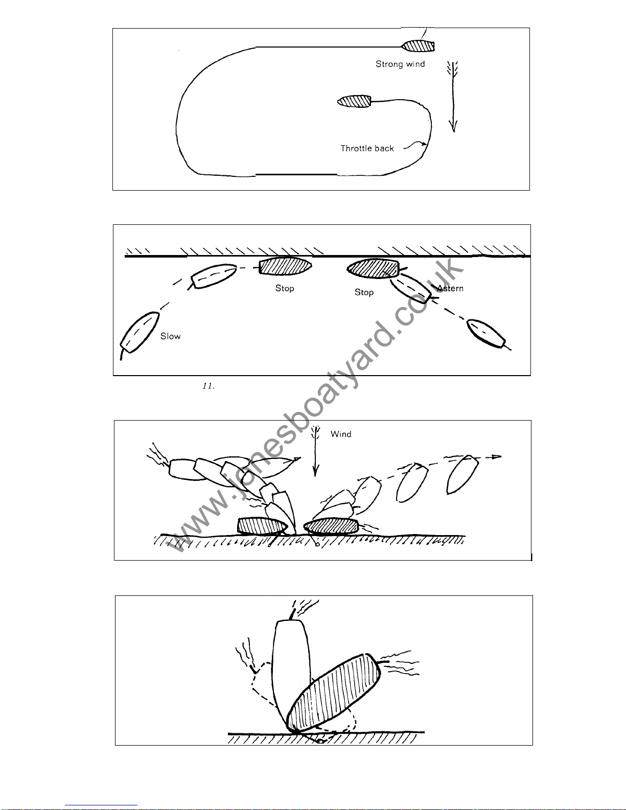
The direction the propeller rotates has a certain influence on a motorboat. Figs. 7 to
13 show this. It can be added that the rudder effect when going astern is not as good
on boats with the propeller sheltered behind a deep keel as on boats where the
propeller and rudder are completely unsheltered. It would be wise to practice all
types of manoeuvering on open water with different wind directions. From such test
manoeuvers
it
will be possible to judge and make successful manoeuvers in difficult
situations later on. The effect of the wind on the boat is mostly felt at low speeds and
can be rather large. A good knowledge of this effect, the bestspeed
for
manoeuvering,
radius of turns i n different situations, influence
of
the propeller, etc. is necessary if
you are t o manoeuver without risk
of
damage t o your own or other boats. With the
propeller thrusting
-
propeller wash against the rudder-the turning radius is about
a
boat lenght. There i s no great difference in turning radius between low and high
speeds. From full speed ahead you can stop the Albin
25
in one boat lenght i f the
gearbox i s used in the right way.
7
www.jonesboatyard.co.uk
Page 9
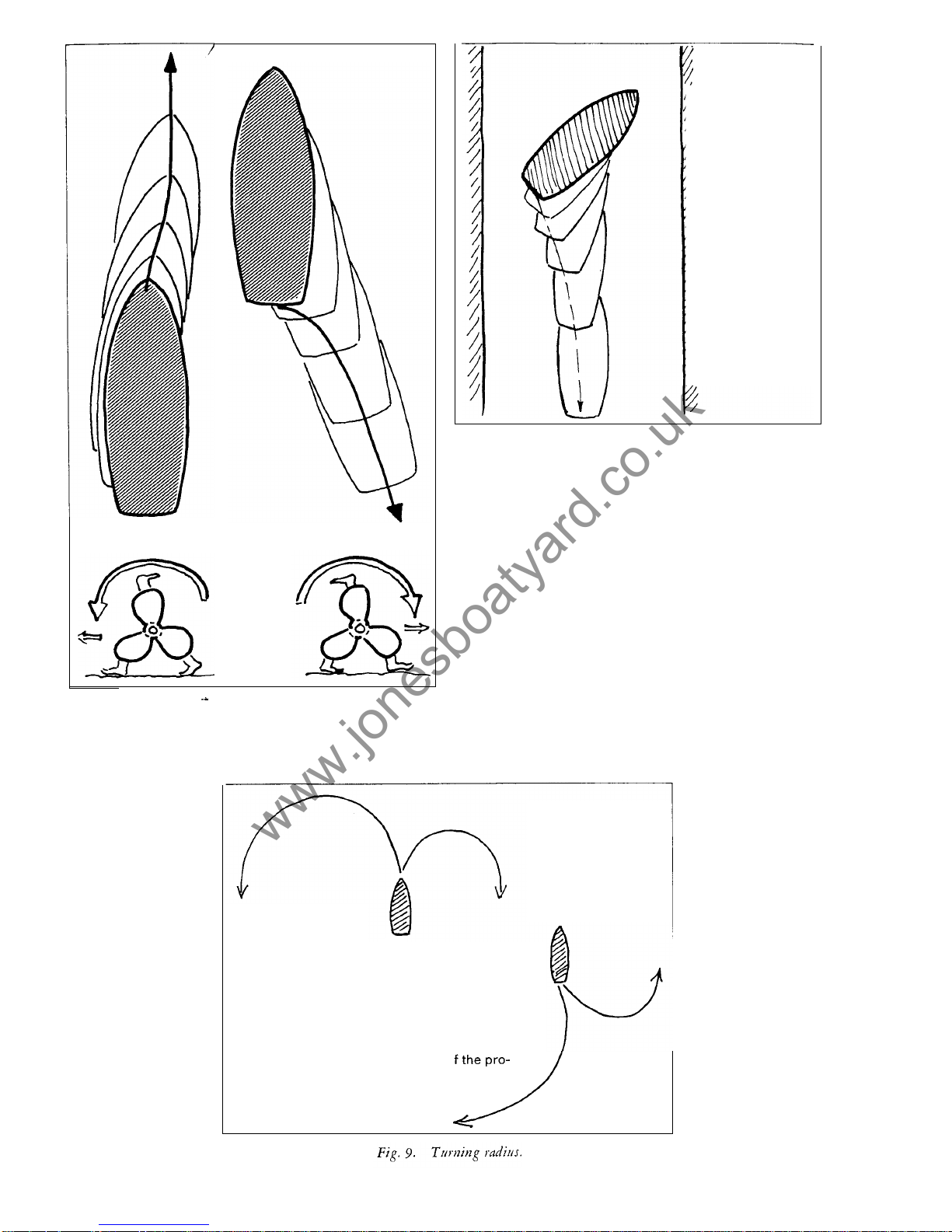
To
be able to go
astern in the in
-
tended direction it
is important to
have the right
initial position.
I
Fig.
8.
Initial position when going astern.
Fig.
7.
The propeller
of
the Albin
25
is
anticlockwise (look-
ing forward seengoing ahead)
The rotating propeller stream
pushes
on
the keel and bottom.
In
the lower positions the pro-
peller blades work
in
less disturbed water. This adds up to a side
force, which is noticeable when starting
from
laying still es
-
pecially when going astern.
Theturning radius
can b e influenced
bywind andwaves.
When going ahead
the turning radius
it's slightly smaller
when turning
to
star
board than when
turning
to
port.
t
When going astern
from lying still the
turning radius
is
very much influ
-
enced by the side
force o
peller.
8
www.jonesboatyard.co.uk
Page 10
Full
rudder and power
during the whole turn.
Full
power
Fig.
10.
When
turning
against the w
ind
the
turning
radius can be smaller than when
turning with the
wind.
\\
\
\
\\\
\
\
\\
Astern
speed
Slow speed
\\\
\
\
\\
Astern
speed
Fig.
Approaching a quayside. With the port side against the quay the manoeuvre is
best done with
a
continous turn. Approaching with the starboard side is done on a stright
course. The propeller sideforce lays the boat smoothly alongside when going astern.
I
T o leave a quayside when the wind is blowing against it.
If
the port side is tied
Fig.
12.
to the quay it is easier to go astern
and
get off
.
Fig.
13.
The engine can be used
to
turn
the boat with the stern against the quay.
9
www.jonesboatyard.co.uk
Page 11

First launching
Albin 25 is delivered in a shipping cradle which has been with the boat since she first
took shape. The boat is fastened to the cradle with two iron rods which tie down the
middle at each side. The rods have threaded ends and nuts at the deck and at the
cradle below.
A
crane and lifting straps are needed to lift the boat out of the cradle.
The recommended launching procedure
is
as follows:
1.
2.
3.
4.
5.
6.
7.
8.
9.
10.
Learn beforehand about the mooring place you will use after launching and check
that necessary lines, fenders and anchors are handy.
Loosen the nuts on the rods at the deck
so
that the rods can glide down and
the boat is free from the cradle.
Put the strops around the boat ahead and astern of the cradle. The strops are
then hooked into the lifting hook of the crane. When the strops are tightened
their position should be corrected
so
that they do not touch any sharp edges.
Check: that the bottomdrain plug is closed,
that the seacock for the engines cooling water isopen,
that the engine cooling water draincocks on the port side of the engine
Close the seacocks for the discharge
of
the toilet, washbasin and sink to avoid
possible risk
of
leakage during launching. They can b e opened one at a lime for
checking when the boat has been launched.
Check for water in the bilges, looking under all floorboards. If there
is
any water
open the valve to the automatic bilge pump on the motor which will then pump
out the water when the motor has been started. This valve should be closed
when the bilge pump is not needed.
Lift the boat free from the cradle.
The unpainted portions
of
the boat which have been against the cradle are now
painted with the paint delivered with the boat.
Lift and launch the boat.
Loosen the straps on one side of the boat and let the crane lift the straps up on
the quayside. The engine was test run before delivery and there is fuel in the
tanks for several hours running. Check the level in the battery and the o il level
in the engine
-
in addition to the checks mentioned in paragraph4above. Top
up with fuel as soon as possible.
Follow
the instructions i n next chapter when
starting the engine.
are closed.
Engine installation and maintenance
The Albin AD-21 engine has only one lubricating point which is situated in the aft part
on the top
of
the engine. The oil filler point and the dipstick are very easy to reach
through the circular inspection hatch on the
top
of
the engine cover, fig.
14.
Reverse gear,
reduction gear and fuel injection pump are Iubricated from the common lubricating system.
When changing the oil 3-3.5 litres (0.65-
0.75 Imp. gal.,
0.8-0.9
US.
gal.)
of
new oil
will be needed. O il has to be changed every
100
hoursoronce each season if the engine
is used
a
shorter time during the season. The
first oil change should be made after
25
hours
running. Empty the used oil when the engine
is warm with the help of the oil pump which is
included with the tool kit. The lubricating oil
filter cartridge should be changed every
300
hours or once a season at the same time as
the o i l change.
The engine is cooled with sea water. The cool
ing water pump and the automatic bilge pump
are builttogether in the same unit. Bothpumps
are a rubber impeller type and the bearings
are water lubricated. The working temperature
of the engine is regulated by a thermostat.
The right temperature is 70-85°C.
10
www.jonesboatyard.co.uk
Page 12
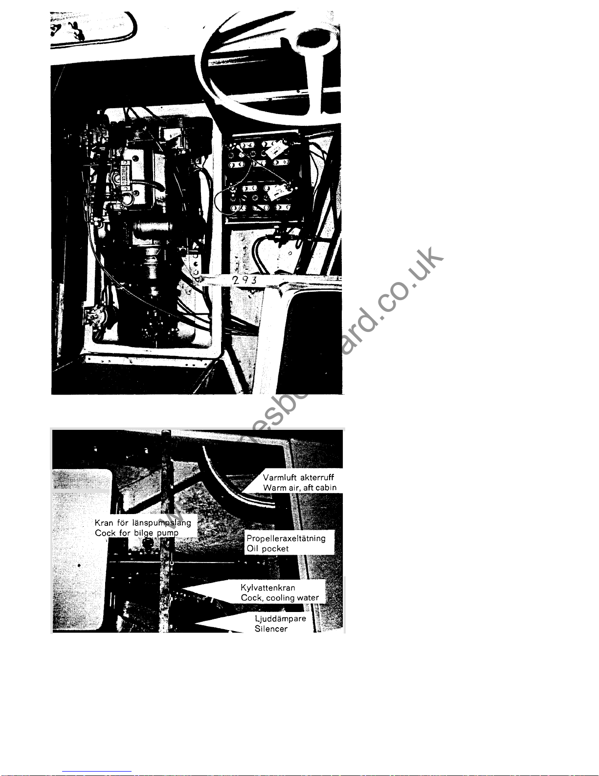
The reverse gear is a spring loaded type
which is self
-
adjusting. In neutral the reverse
gear is completely free when the propeller
shaft i s standing still.
Procedure before the first start
Beforethe engine is startedthe first time after
launching the following precautions should be
taken.
1.
2.
3.
4.
5.
6.
7.
Fig.
15.
Engine installation and batteries.
8.
Fig.
IG.
Propeller shaft with oil pocket, cooling water seacock
and
cock for
9.
bilge pump.
Remove the helmsmans seat. Remove the
floorboards and the floor over the battery
box (under the helmsmans seat). Unfasten
the clasps on the engine cover and fold it
aft (fig. 15).
Check the acid level in the batteries. The
level should be about 10 mm above the
plates. Fill with distilled water if the level
is too low.
Check that the battery cables are con
-
nected.
The motor has been filled with lubricating
oil at delivery. Recheck the oil level. It
should be between the two marks on the
dipstick not lower than the lower mark
and not higher than the upper mark.
Check that the cooling water seacock is
open (fig. 16).
Open the bottom screw on the fuel line
water separator and drain away any con
densed water which may have gathered
here.
When delivered, around
15
litres of fuel
mixed with inhibiting oil i s pu t in the fuel
tank. Before starting the tank ought to be
filled with ordinary diesel oil, such as car
diesel oil.
When the engine i s tested before delivery
the fuel system
is
bled free of air. It would
be wise to do this again before the first
start. It is important to know how to bleed
the fuel system in case you happen to get
air in the system while away cruising.This
can happen i f the fuel level is too low and
the boat is rolling heavily. Try not to allow
the fuel level to fall below 10to 15 litres.
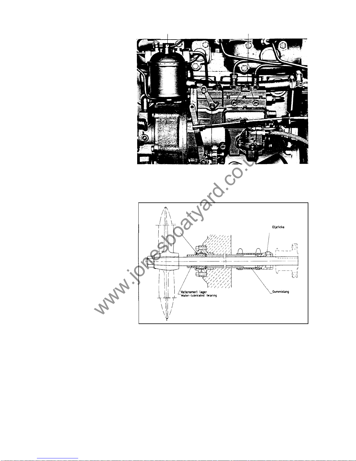
The bleeding is preformed as follows (fig.
17):
The fuel i s pumped using the manual
pumping lever. With long strokes at least
30
vertical movements will be necessary.
Then slacken the nipple bolt for the return
oil line to the fuel tank. This is fitted
on
top of the fuel filter. Continue pumping
until fuel free from air bubbles flows out.
Closethe bolt. Open the front bleed screw
on the fuel injection pump. Now pump
again with the pumping lever until fuel
free from air bubbles flows out. Close the
bleed screw.
Unscrew the plug on the propeller shaft
oil pocket (fig. 16
&
18) and check that it
is almost filled with grease. Fill with more
grease if necessary.
A
soft outboard grease i s most suitable. The grease is
pressed directly from the tube until the oil pocket is almost full.
Do
not use high
pressure.
A
grease gun must never be used as this may press out the forward
sealing ring.
Do
not overfill the oil pocket as even screwing down the plug may
exert enough pressure to push out the sealing ring.
11
www.jonesboatyard.co.uk
Page 13
10. Replace floorboards, engine cover and helmsmans seat. The engine is now ready
for starting.
1
2
Fig. 17. fuel injection pump and fuel filter.
1.
2.
Bleed screws
3.
Manual pump
4. Cold start button
Bleed screw
for
fuel filter
I
4
I
3
Rubber bushing
Oilpocket
Rubberhose
Fig.
18.
Propeller shaft sealing and bearing.
Starting
1.
2.
3.
Check that the cooling water seacock is open.
Check that the stop control is pushed in (fig. 19).
Disengage the control lever with the disengaging latch (fig. 19) and move the
control lever ahead to the starting position (position
7
in fig. 21).
Insert the starting key and turn i t t o position
1
in fig. 22.
Check that the yellow warning light for oil pressure and the red warning light
for
charging are on.
Push the starter switch key and turn clockwise to position
2
in fig. 22. Hold the
key there until the engine starts. The key when releasedwill returnto the switched
on position (position
1
in fig. 22).
4.
5.
6.
12
www.jonesboatyard.co.uk
Page 14
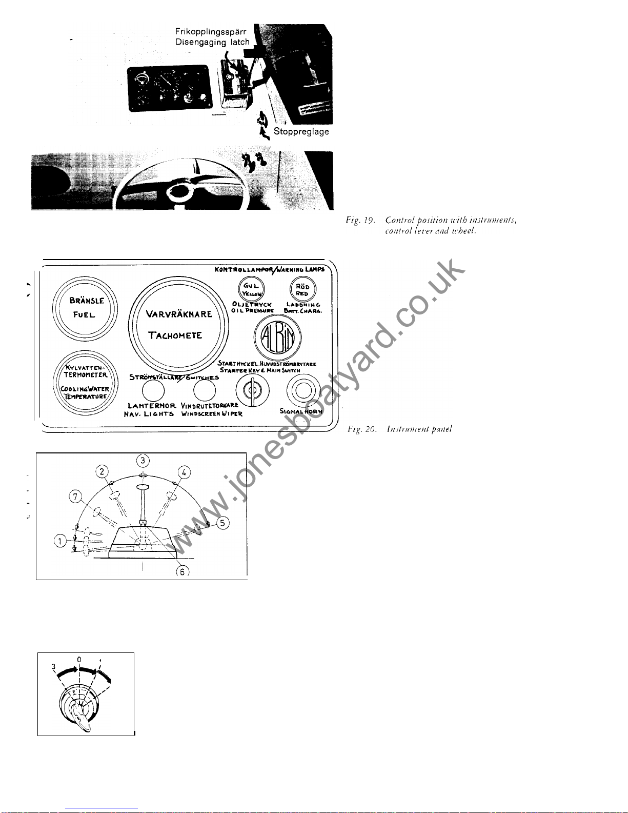
Stop control
R
HORN
Fig.
21.
Teleflex c
ontrols.
"
Ahead
"-max.
4.
"
Astern
"-idle
speed
"
Ahead"-
idle
Neutral
7.
Starting position
5."Astern
"-max. speed
6.
Disengaging latch
I
2
0.
Neutral position
1.
Switched-on position
2.
Starting position
(starter motor
Fig.
22.
switched on)
Starter
switch
key.
3.
"
Radio"position
7.
Move the control lever back to neutral when the engine is run
-
ning evenly (position 3in fig.
21).
Check that the yellow oil pressure warning light and red charg
-
ing warning light are out when the motor is running.
Check that cooling water is discharged through the exhaust
opening.
8.
9.
NOTE: The starter switch is also the main switch for the electrical
system of the engine. Because the engine is equipped with an
alternator the starter switch key must not be turned to off (position
0
in fig.
22)
when the motor is running as the alternator rectifier
diodes could be damaged. For the same reason the battery cables
should never be disconnected or reconnected to another battery
while the engine is running.
NOTE: If the engine is difficult to start in cold weather the cold
weather starting buttonon the fuel injectionpump should be pushed
in. This will supply a richer starting mixture. Set the control lever at
the starting position (position
7,
fig.
21)
then pushthe coldweather
starting button. It will remain in until it automatically releases when
the engine starts. The position
of
the button is shown in fig.
17.
With a little effort it is possible to reach the button through the
inspection hole i n the engine cover.
If
a spray can with"starting gas"is used the cold weather starting
button need not be used. Remove the inspection hatch on the engine
cover. Use the left hand to spray down in the opening (against the
air filter) and at the same time turn the starter switch key to the
starting position. This will help t o start the engine very quickly.
13
www.jonesboatyard.co.uk
Page 15
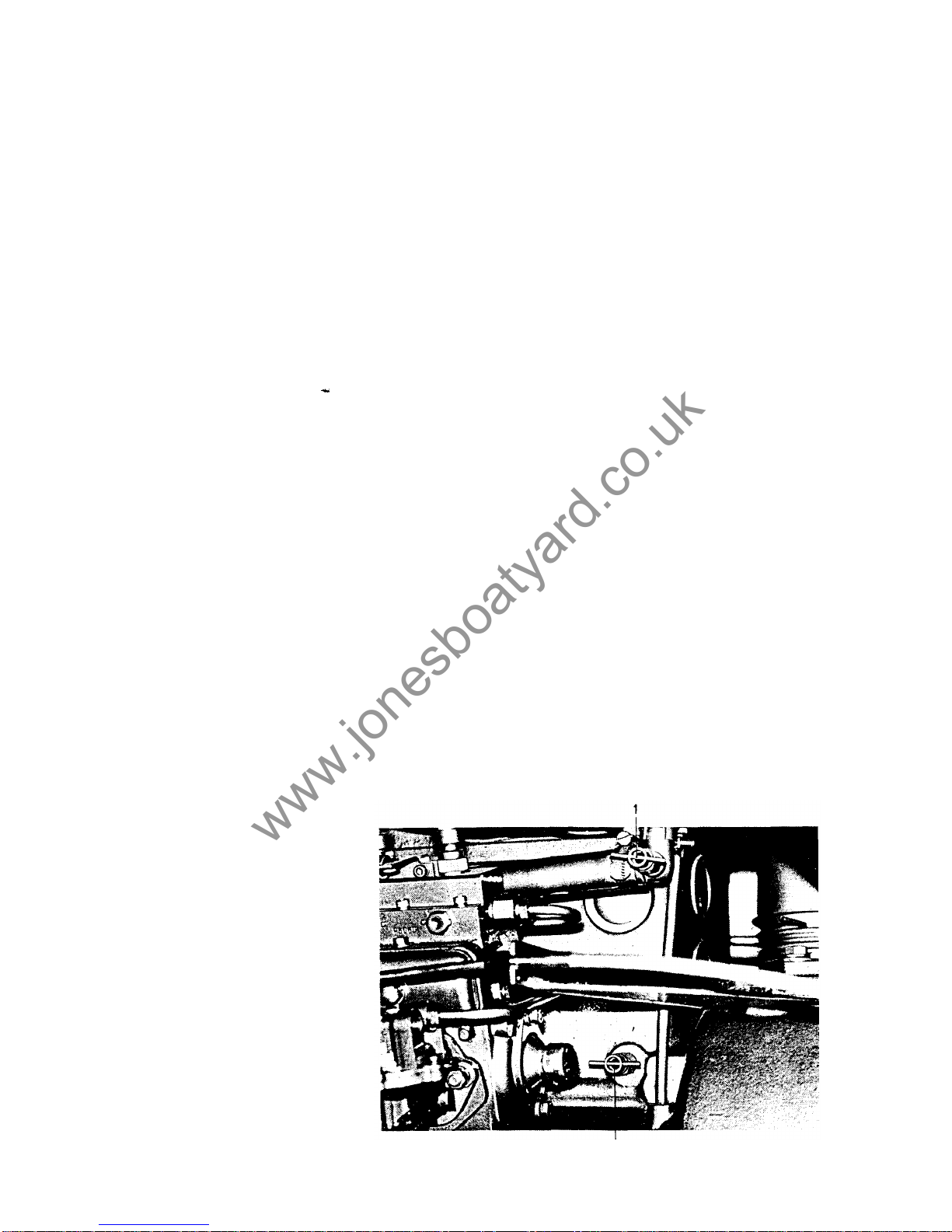
Manoeuvring
The spring loaded type reverse gear requires little operating effort. This makes it
possible to use a single lever control. With this type
of
control, both the reverse
gear and engine speed are operated by means of the single control lever.
All manoeuvring should be made with distinct movements from neutral to ahead o r
astern position. Positions between the marked positions 2,
3
and 4 in fig. 21 may
damage the reverse gear. When the lever goes into the proper position a definite
indentation can be felt. With the control lever in neutral (position 3, fig. 21) the
propeller is not coupled to the engine and the engine is idling at about
650
rpm.
Moving the lever forward to position 2 couples the propeller to the engine at idling
speed. Moving the lever farther forward increases the engine speed. When the lever
is moved backward to position 4 the propeller is coupledto the engine at idling speed.
The propeller is now turning in
a
reverse direction. Moving the lever farther back
increases engine speed.
The engine can be run at maximum rpm (2300 to 2400 rpm) fo r long periods but
2000
rprn will give much more economical cruising. Recharging of batteries during short
periods of up
to
30 minutes can be done with the engine idling and the control lever
in neutral, Charging for periods of several hours should be done with the gearbox
in forward. The engine must not be run with the propeller disengaged for any lenght
of time at higher than idling rpm.
Running
At regular intervals when running check:
that the cooling water temperature is 70-85°C;
that the warning lights fo
r oil pressure or battery charging are not lit;
that enough fuel is available;
that the lubricating oil level is right. This should be done after the engine has been
stopped f or
30
minutes giving the oil time to run down to the oil sump. Over
filling with oil can result in oil being pressed out through the aft crankshaft seal
and being thrown around inside the flywheel casing;
that the automatic bilge pump intake is shut
off
when not needed (fig.
16).
The back
vent on the pump contains a ball vent which could, if held partly open by dirt
particles, cause flooding of the boat. Shutting off the valve also prevents intake
noise. Note: When closing this valve, be certain you are not closing the valve
for the engine cooling water;
that the acid level in the batteries is about 3/8 inch above the top of the plates. If i t
is low add distilled water;
that no water has collected i n the fuel line water separator. Any water should be
drained o f f through the bottom screw.
Fig.
23
Drain
cocks
for cooling water.
1.
Cockfo r exhaust manifold
2.
Cock for engine block
14
2
www.jonesboatyard.co.uk
Page 16

Stopping
1.
Place the control lever in neutral
2. Pull out the stop control.
As
soon as the engine has stopped, push in the stop
control again. Make it a habit,then you won't runthe risk of using u p unnecessary
current next time you try to start with the knob out.
Turn the starter switch key back from position one to the neutral position (posi
-
tion0)and remove the key.
3.
Prevention of
frost
damage
In spring and autumn when there is a risk of freezing temperature the following steps
should be taken.
1.
2.
3.
After stopping the engine close the seacock on the cooling water intake, fig. 16.
Open the cooling water draincocks on the engine block and exhaust (fig.
23).
When the water has drained, start the engine and run for one minute butnolonger
as the impeller pumps can be damaged. During this minute the engine should b e
run for short bursts up to 1500 rpm. This will blow all water out of thaexhaust
system.
Rustproofing t he engine for winter storage
The following steps should be taken.
1.
Add inhibiting oil such as
Esso
Rust Ban 623 t o the fuel tank giving a fuel mix of
5%. If there is about 10 litres of diesel fuel left in the tank put in about
'/2
litre of
inhibiting oil.
Run the engine at least one hour. While the engine is still warm the lubricating oil
should be changed.
Clear the cooling system of water as described in the frost prevention paragraph.
The batteries should b e removed and stored fully charged in a place protected
against frost.
2.
3.
4.
Procedure before the first start next season
1.
2.
3.
4.
5.
6.
Replace th e batteries, fully charged and checked.
Change
oil
and fuel filters. Check that there is no water in the fuel line water
separator. When changing the fuel oil filter it is a good idea t o use a plastic bag
around the filter from the underside
so
that the leaking diesel fuel is contained
inside the bag.
Top up the fuel tank.
Bleed any air from the fuel system.
Check that the cooling water seacock is open.
Put grease in the propeller shaft oil pocket.
Interior and equipment
Varnish, glue a n d fastening
The interior joinery is mainlyofresin glued marine plywood with surface veneers
of
sapele on gaboon cores. The finish should normally last f or several years but its life
may be prolonged b y polishing with furniture polish. After a period the surface
finish will have to be renewed. The varnished parts can be treated with either alkyd
or polyurethane based varnish in accordance with the manufacturer's instructions.
15
www.jonesboatyard.co.uk
Page 17

Other parts can be painted with marine paint. Teak (handrails, etc) should be oiled
several times each season. When necessary, the teak parts should be scraped and
sanded. The best and cheapest
"
teak oil
"isa mixture of two parts raw linseed
oil
and one part turpentine thinners. Itcan be put on with either a brushora soft cloth.
Excess oil should be wiped off with a cloth moistened with thinners. If you wish to
fix hooks or other fittings to the boat they can either be screwed or glued on. Fittings
can be screwed to all wood parts. Holes should b e drilled for screws. Fittings that
do not carry a great load can be screwed on to plastic surfaces with short stainless
steel self tapping screws.
It
is very important that the right size holes are drilled first.
A
dab of epoxy glue on the threads will provide considerable holding power. Epoxy
glue is
so
strong thatitcan be used to glue metal fittings on to the plastic surfaces.
This cannot be done, however, on thermo plastic.
Fittings that have to take a load must b e attached with through bolts. The sandwich
deck will take the load of such bolts only where the deck is filled with wood
or
spe
-
cial filler. If bolts must be used in other places, the Divinycell filling should be re
moved round the hole and glassfibre and resin ora polyester putty put to form a
strengthening
"
tube"round the bolt. Apiece of wood should be fitted under th e
nuts to spread the load. Bolt holes will leak if the bolts are not packed with a rubber
gasket or sealing compound. Glassfibre does not expand when moist,
so
leaks are
not self sealing as is sometimes the case with a wood boat.
The curtains are cotton and can b e washed in water. For the carpets a foam detergent
can be used. The covers for the matresses are synthetic and may be removed and
dry
-
cleaned, but itisa lotof work to p ut the covers back again. With a foam detergent
it is possible to wash the covers without removing them. Test the detergent on a spot
on the back side to ascertain that th e colour does not face.
Fresh water
The water tank holds
65
litres (14% gals). The deck filler is situated right forward
on the fore deck. The level of the water in the plastic tank can be checked through
the vertical opening in the bulkhead aft of the tank.
A
thin breather pipe which finishes
just under the deck is fitted parallel t o the filling pipe. If the tank is completely filled
the water level will rise up the breather pipe and a small amount of water will find
its way into the bilge; it can be removed easily with the bilge pump.
If
the tank is
completely filled a small amount
of
water may also run out into the sink and wash
basin. The tank and supply hoses can be flushed through continued filling of the
tank filling pipe. Water can then run freely through the system, into the sink and
overboard.
A
large lid is fitted to the tank to facilitate inspection and cleaning. The
forward foot pump in the galley is for fresh water and the aft one for sea water.
Skin fittings and
hose
clips
All
skin fittings below the waterline -inlet and outlet from the toilet, outlet from the
sink, sea water intake for the galley, and cooling water for the engine have sea
cocks to prevent the water from entering the hull if a hose or pipe should be damaged.
Skin fittings for the exhaust have no sea cocks since they can be reached from deck
and bunged up if need be.
All
hose attachements should be checked regularly for leaks and the hose clips
tightened if necessary.
Ventilation and heating
The ventilation system has been designed with scientific thoroughness by a former
chief of Swedish defence research, Hugo Larsson. This is probably the only system
that provides a well ventilated and dry boat without the use of electric fans. On hot
summer days the temperature inside the boat will be cooler than that outside.
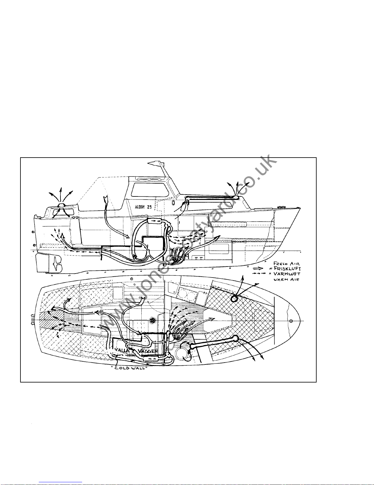
The system is based on the principle that all fresh air is let into the accommodation
space from deep down in the cockpit. For proper efficiency the cabin doors should
be closed. This ai r flows down along t he inside of the cold hull below the waterline.
The moisture in t he air condenses on the cold surface where it runs down into the
bilges. The dehydrated air is then led t o the fore and aft cabins. Fig. 24. Stale air is
evacuated through three electrolux ventilators which were first developed by Hugo
Larsson f o r th e Vega. These ventilators withdraw air from the cabins whenever there
is any outside air motion over them regardless of direction. With a wind speed of 4
metres per second, approximately
8
knots, one ventilator can suck ou t15cubic
metres of air per hour. The air stream passing up through the ventilators can be
regulated or completely closed off b y a knob (not the toilet ventilator). The starbord
16
www.jonesboatyard.co.uk
Page 18
forward ventilator sucks out aidfrom the toilet compartment through a duct inside
the deck. A closed up, stationary Albin
25
can have an inside temperature 5°C
lower than outside on a hot summer day. Without this ventilation system the boat
would be like an oven. The deck has good insulation through its sandwich construc
tion and the inside of the hull is insulated with a lining of plastic covered textile and
foam. This insulation and the ventilation system combine to keep the boat very
moisture free during normal conditions.
If
an Eberspacher boat heater is added to the ventilation system it is possible to keep
the boat warm and dr y even during very low temperature conditions. The Albin 25 is
planned for such an installation. The principle function of the heating system is shown
in fig. 24. In the completely enclosed combustion chamber of the heater, diesel oil is
burned. It
is
pumped from the main fuel tank b y an electric pump. The air f or com
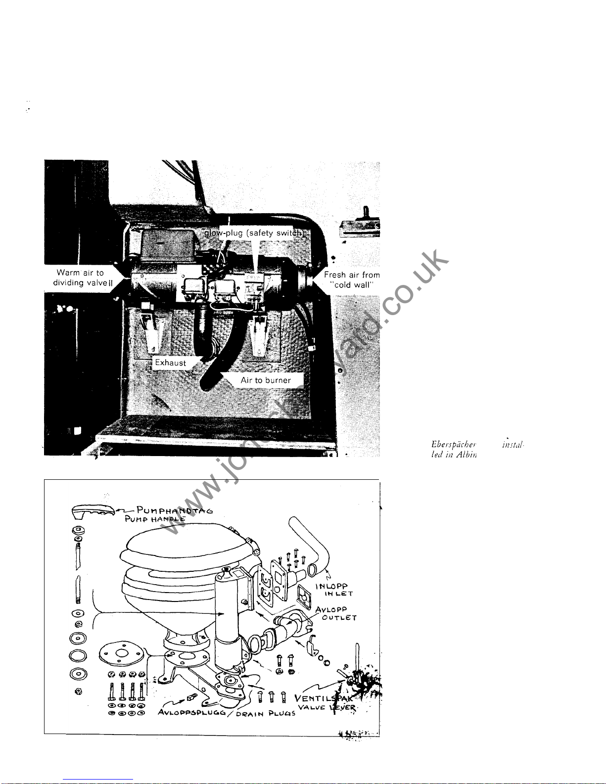
bustion is taken from outside directly through the hull and the exhaust gases are let
out through the exhaust tube placed over the intake for combustion air. Fig. 25. This
makes the condition for even burning more certain. A wind blowing against the ex
haust opening gives the same pressure at intake and exhaust. A fan in the heater
sucks fresh air from the space with the cold wall and the air is heated when
it
passes
around the combustion chamber. The heated air is lead through a duct to a dividing
valve on the bulkhead by the control position. This valve can control the passage of
hot air to one or both cabins.
Fig.
24.
The ventilating and heating systems.
The heater i s started with a switch on the bulkhead at the far side of the toilet. Near
this switch is a thermostat where the temperature for the forecabin can be regulated.
The temperature in the aft cabin i s dependent upon how the dividing valve is placed.
To hold the inside temperature 10
-
15°C higher than t h e outside temperature the
thermostat normally has the heater going about 25% of th e time, that is 15 minutes
out of each hour. With the heater running continuously fuel consumption is about
C.3
litres an hour and with the thermostat working about 0.1 litre per hour. A t the
start the heater requires 18 amperes starting current for
30
secs., after which the
17
www.jonesboatyard.co.uk
Page 19
current consumption is about
3.5
amps. When the heateristurned off the fan con
tinues to run a f ew minutes to cool off the combustion chamber. With a fully charged
battery of
57
amp. hours, t he heater can be run a coupleofnights before the battery
needs recharging. Care must be taken that the heater exhaust fumes do not damage
fenders or cause annoyance to nearby boats. Special,instructions give further in
-
formation for the running and maintenance of the heater and also technical data.
.
18
Fig.
21.
Fig.
26.
Toilet.
heater
25.
www.jonesboatyard.co.uk
Page 20

Marine toilet
Use only toilet paper and not to much of it!
Fig.
26 shows the toilet type "Brydon
Boy
"
. It is flushed in the following manner:
1.
2.
Open both sea cocks (inlet and outlet)
Move the small valve lever to
"
flush"and pump until only water is left in bowl
and then pump still more.
Put the lever on
"
Dry Bowl"and pump until bowl is dry. The pumping is much
harder now. If necessary, wipe off with paper
-
switch from "dry"to"flush".
The lever should be positioned on
"
Dry bowl"when the toilet is not in use
In heavy seas or when leaving the boat the sea cocks should b e closed.
3.
4.
5.
Maintenance:
Do
not use strong detergents -they can damage hoses, rubber gas
-
kets and valves.
When laying up one of the red drain plugs in the lower part should be opened
so
that no water is left to freeze. Pump a few times.
After use in saltwater the W.C. should be flushed with freshwater to be ready for
use the next season. The W.C. should of course be cleaned.
Normal maintenance during a season may be a few drops of oil for the pump lever.
Leaks can occur at hose clips and gaskets. They may need tightening.
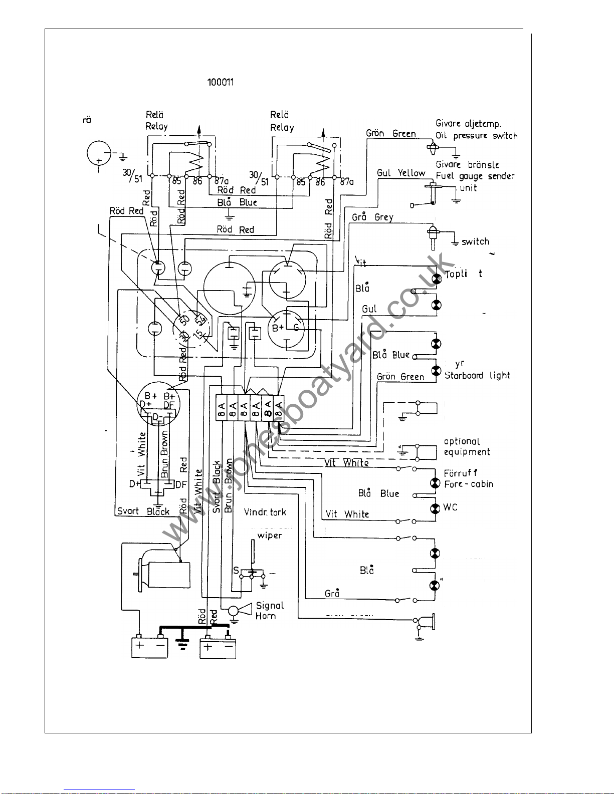
Electrical System
A
12 volt electrical system circuit diagram i s shown in fig. 27 (1970 boats) an d 28.
(Boats from the 1971 series). In the later boats the charging of the boat batteries i s
regulated by a diode (when the lighting battery is fully charged the starting battery
starts charging). The first Albin 25 boats (1969) were equipped with only one battery.
The circuit diagram f or these boats was delivered in a special instructions. Some
of the electrical cables run in conduits in the deck. Beside the steering wheel there
is an electrical connection which can be used for various appliances such as a hand
lamp, vacuum cleaner, razor, etc. U se the proper plug in this connection as the
wrong one can cause a short circuit. The horn, windscreen wiper, electrical outlet,
navigation lights and other lights are protected with
8
amp. fuses (Bosch
MSG 3/4
Z.,
length25mm). There is an extra fuse fitted for the addition of extra equipment such
as refrigerator or heater (25 Amps needed). The fuses are fitted in a box on the aft
.bulkhead of the toilet room.
There
is
a spare fuse in the box. The lighting system is12volts and uses the following
lamps: Navigation lights:
10 watt (Osram) 44 mm long
-
reading lights: 10 watt
(Osram) 44 mm long
-
overhead cabin lights: 15 watt (Osram 7430 bayonet base
BA 15 d)
-
tachometer light: 4watt (Osram893)-other instruments: 2 watt (Osram
3898)
-
warning lamps:2watt (Osram 3796). 10 watt lamps us e about .85 amps., 15
watt lamps about 1.25 amps.
If
a lamp or any other equipment does not work when the currentisswitched on,
check the fuse first. If the fuse is alright either the lamp is burned out or there is a
poor connection in the wiring. If the fuse is blown change to a new one. If this one
should blow also, then there is a short circuit in the wiring or the fixture. If one fuse
in particular blows often, it could mean that the curcuit is loaded with too much
additional equipment. The8amp. fuse can be replaced with a 15 amp. fuse. For a
heater a 25 amp. fuse is needed. Never replace a fuse with a piece of wire as this
will leave the circuit unprotected. When idling, the chargi&$power is about 200 watts.
Full charging power of 490watts i s available at 2000 rpm.The charging relay switches
off charging current when the battery is fully charged.
It
is preferable to charge
batteries slowly, with a low charging current available at 1000 rpm. Remember, the
engine must not be run at idling without the propeller turning longer than thirty
minutes. At 2000 r pm
a
battery can be fully charged in 2-4 hours.
19
www.jonesboatyard.co.uk
Page 21
I
I
I
I
Generator
Alternatoi
Rc
la
Relay
Bosch
0
332
Bosch
0 332 003011
Albin Motor
75974
Albin Motor
75975
Startmotor
Starter motor
Ti
m
kna
r
e
Hour Metcr
Conncction for
Windscreen
Givare vattentemp.
Watcr temp.
White
.
Topplantcrna
g
h
Akterlantcrna
Yellow Stern
light
Blue
Rod Babordlantcrnc
Rcd
Port
light
Stbordlanterna
Uttay
for
extra
ut rustning
Brun Brown
Aktcrruf
f
Aft-cabin
Blue
Doghouse'
Grey
Gron
Green
El.u ttag
Connection for
Start batteri Belysnings batteri
Starting battery Lighting battery
vacuum cleaner
or
hand lamp
Fig.
27.
Circuit diagram for.Albin
25,
1970.
20
www.jonesboatyard.co.uk
Page 22
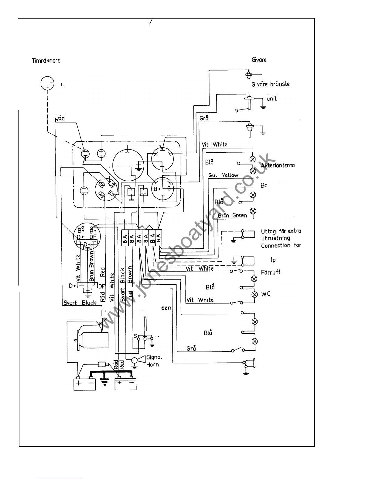
Hour
meter
Generator
Alternator
Ra
la
Relay
oljt.
Gron
Green
Oil
pressure switch
Gul Yellow Fuel gauge sender
Red Grey Givarc vattentcmp.
Water temp.
switch
Topplanterna
Top
light
\
optional
equ
m
ent
Fwc- cabin
Startmotor
Starter
motor
c
-
Vindr. tork
Win dscr
wiper
Stern light
Blur
Rod Red
bordlanterna
Blue
Port
light
Sty
r
bordlanterna
Starboard light
Blue
Akterruf
f
Aft-cabin
'Dog house
"
Brun Brown
Blue
Grey
El.
uttag
Connection for
Gron Green
vacuum cleaner
or hand lamp
Start batteri Belysnings batteri
Starting battery Lighting battery
Fig.
28.
Circuit diagram for Albin 25, 1971.
21
www.jonesboatyard.co.uk
Page 23
Refrigerator
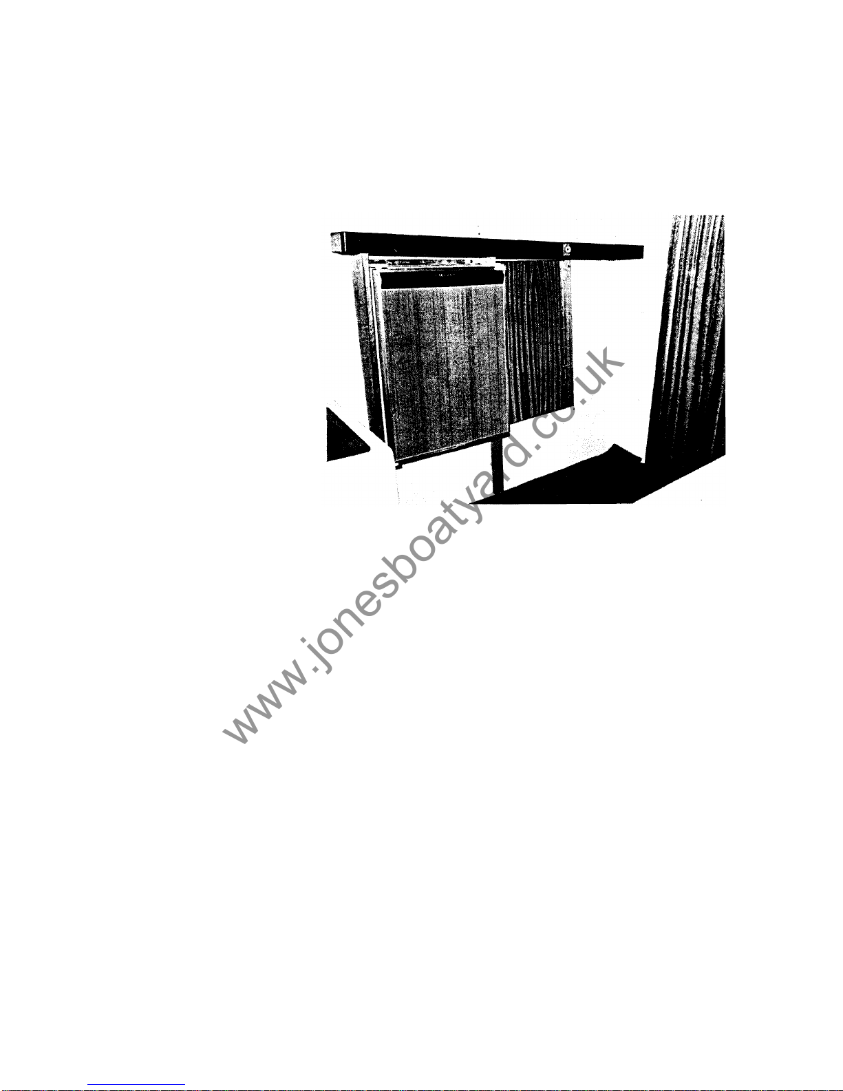
A refrigerator with a capacity of 42 litres can be installed in the stowage compartment
on the port side fig. 29. The electrical power needed is maximum 25 watts (4.5 amps.)
but used normally the mean current is about 2 amps. This means that
a
fully charged
battery has a capacity of running
a
day and a night with the refrigerator only -after
that the battery has to be charged. If a refrigerator is installed it is advisable to add
still another battery as a spare or coupled in parallel with the lighting battery. The
refrigerator is switched on with a switch placed just aft of the refrigerator. A warning
l
amp near the switch shines when the current is on.In earlier installations the switch
was
at t h e helmsmans seat without a warning lamp.
Fig.
29.
Refrigerator installed.
Cockpit cover
The cover is made from a
type
of synthetic canvas.
It
is
colourfast and treated to
make
it
waterproof while allowing air to pass through. This has the advantage that
the formation of condensation under the cover is kept to a minimum. Wet covers
should b e dried in a stretched position. When new they shrink a little and they can
form a poor fit if they are not dried in their right
form.Do not store the cover while
it
is
damp as mildew can form and damage the material. The cover canvas should
be brushed ocassionally. Salt, dirt, etc., can be brushed off and washed away with
clean water. Detergents and solutions wash away the waterproofing. If it is necessary
to wash away oil stains, etc., a soap detergent must be used and not strong solvents.
After washing the canvas must b e impregnated with new waterproofing. Water
proofing for tent canvas can be bought i n paint shops and is available in spray
containers. Leaks in covers can be made water tight with a rubber solution or par
-
affin.
Equipment
The Albin25has fairly complete equipment but certain extra equipment is necessary
for instance: anchor and anchor line, fenders, stove, compass, etc. In these cases
personal preference for different types make i t difficult to include this equipment as
standard. Different use of the boat and personal taste can influence what is needed
for the boat. A price
list
from Albin Marin A 6 on extra equipment can give some
ideas regarding the optional equipment that is available for the Albin 25. The following
list may also help.
Extra
equipment
Alcohol, butane gas or paraffin stove. Heating equipment. Refrigerator. Vacuum
cleaner.
Refuse container with plastic bags for disposal i s recommended.
Stem ladder
-
can be stowed under the helmsmans seat with clips.
22
www.jonesboatyard.co.uk
Page 24

Camping table for the cockpit-can be stowed at the side of the helmsmans seat.
Rubber
or
plastic dinghy-can be stowed and fastened athwarthship on top of the
aft cabin.
Cushion to fill the angle between the fore bunks over the lowered table is available.
Stern pulpit is also available for extra safety.
Equipment for the boat
Anchor and line.
A
6
to8kilogram Danforth Anchor or a10kilograms folding anchor
with a minimum of
30
metres nylon line with a diametre of10mm can be considered
a standard anchor for the Albin
25.
A
three metre chain between the anchor and
line prevents the line from being cut or torn near the bottom and increases the
holding power. For bad holding ground and in storms a heavier anchor is needed.
A
long line of elastic nylon helps the anchor hold better.
Three mooring lines (see chapter
"
Tie her up right").6fenders. Spare containers for
extra fuel and water. Paddle. Plastic bucket and sponge. Electric hand lamp with
batteries. Rubber lines and rubber strops for securing equipment.
Tools:
besides the tool equipment delivered with the, boat the following is needed:
funnel for filling fuel tank, some screw drivers of various sizes, adjustable spanners,
polygrip pliers, hammer, combination pliers, knife, etc.
Spares:
Albin Marin A B can supply a service kit of spares containing oil and fuel
filters, impellor, O
-
rings, fuses, bulbs, etc., for about
100
Swed. crs.
A
bigger
kit
is
available at about double the price. Many other things will be convenient to have
aboard such as teflon sealing tape, insulation tape, waterproof tape, on e can o f
lubricating oil, a tube of outboard grease for propeller shaft bearing, also a selection
of screws, nuts, hose clamps, locking wire, yarn, etc.
Safety and emergency equipment
One fire extinguisher o r better two with a sufficiept capacity. Life jackets fur each
person aboard. Life bouy
-
can be fitted on the aft cabin with strops, a self starting
light is advisable. First aid kit. Safety harness with life lines should be used on deck
in bad weather. Emergency signals (at least
6
red rockets). Horn-signals can be
given with the electric horn. Communication radio (citizen band radio).
Navigation equipment
The compass should be a steady, easily read model with internal lighting which can
be connected to the electrical system
of
the boat. Locating the compass at the in
-
strument panel has the advantage of easy installation and good visibility and yet
being out of the way. There is the disadvantage of the electrical cables causing de
viation i n the compass. With the compass properly adjusted the deviation will be
small.
Parallel rulers and dividers should be carried along with thepropercharts of the area
where you intend to cruise.
A distance and speed log can be a great aid
to
navigation, but the
log
should b e
checked for accuracy and calibrated by runs on measured distances.
A
transistor radio will give you the latest weather reports and there are many other
items you will no doubt gather which will suit your particular way of navigating.
Glassfibre and maintenance
The advantages of glassfibre construction
Glassfibre reinforced plastic has very quickly become the leading material for hulls
and decks for pleasure crafts. This depends mainly on the following:
1.
2.
3.
4.
5.
The material is more economical for series production than any other material
used today.
It
has great strength in relation to weight; stronger than wood and steel.
It
has good ageing properties -much better than wood or steel.
The maintenance costs are low
-
small yearly upkeep.
It is easy
to
repair-see below.
23
www.jonesboatyard.co.uk
Page 25
Care of the plastic surfaces
Glassfibre plastic surfaces are easy to maintain. Lack of maintenance will not cause
the material to deteriorate but without care the surfaces will look bad and the value
of
the boat will decrease, Regular cleaning, waxing and polishing are needed.
Cleaning
Wash with water and ordinary synthetic detergents. The deck pattern can be scrub
bed dry with a clean brush and some cleaning powder. Heavily soiled parts can be
cleaned with one
of
the degreasing detergents recommended
for
carsorspecial
boat cleaners.
It
is also possible to use soap. With care also acetone and carbon
tetrachloride can be used. Avoid using scouring powders, strong alkalis (caustic
soda), ammonia
or
any unknown detergents. Stains, small scratches and dull parts
can be polished
or
burnished to regain the gloss.
Waxing and polishing
A
well polished surface protects the gelcoat and is less easily soiled and makes
the boat look better. Polishing puts off the time when it becomes necessary to paint
the plastic because
of
looks.
For
polishing, use a boat, car or floor wax containing
Carnauba Wax. It should be used in the same manner as when polishing a car.
Do
not use silikon polish, since this isvery difficult to remove before repairingorpaint
-
ing. A boat should be waxed and polished at least onceayear.
Repairing small damages
The Albin25small repair kitisused for re
-
pairing minor damages in the gelcoat and the
outer part of the lamination.
For
more com
-
plicated repairs, contact aspecialist.
Prepairing for a repair
Remove dirt in the damage area. Roughen up
the surface in the damaged area with an abra
sive paper. Remove the dust thoroughly and
check carefully that the damage is free from
moisture.
Mixing and applicationofthe gelcoat
Use a piece of board
or
a
piece of wood and
mix the gelcoat with the hardener thoroughly.
The enclosed putty stick can be used
for
mix
ing and application. of hardener should be
used. (This can be approximated).
The ready mixed gelcoat hardens in
15-20
minutes at 18°C
(65°F).
The surface of the
repair should be slightly higher than the
sur
-
rounding parts to allow
for
shrinkage and bur
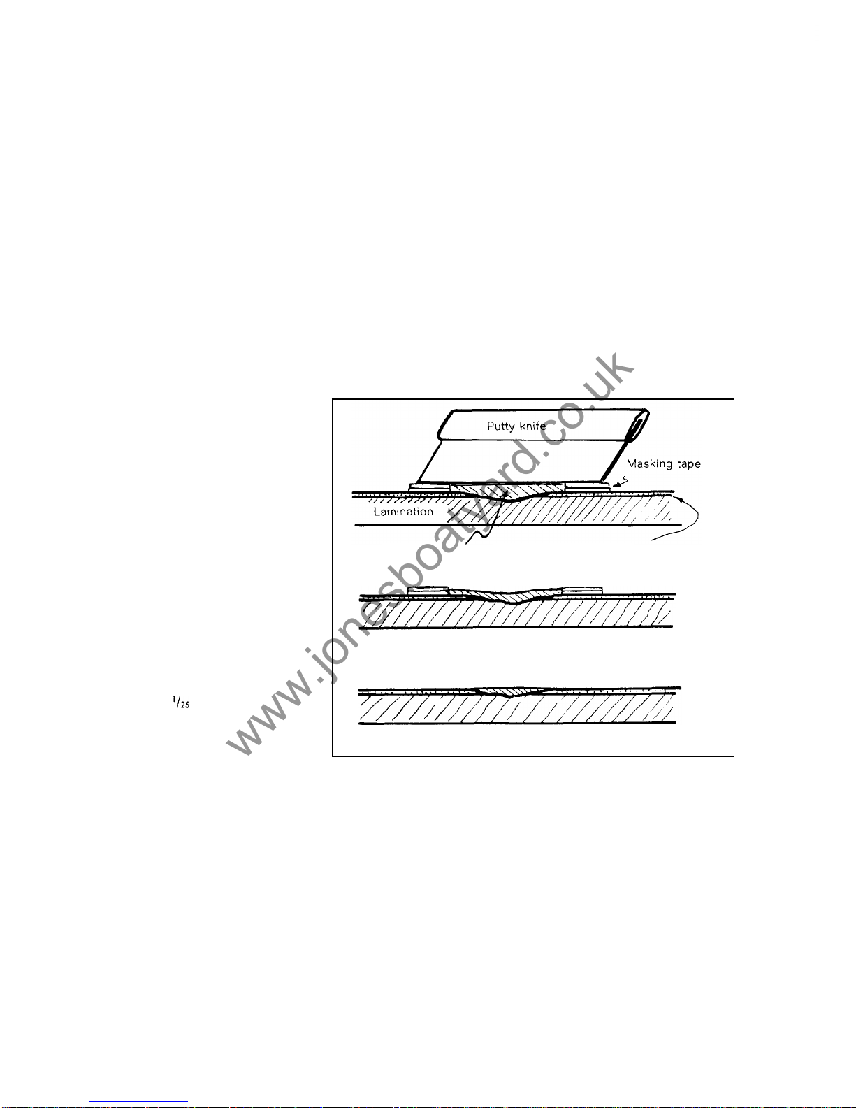
nishing. This is easily achieved through using
masking tape, as shown in fig.
30.
Gelcoat putty Gelcoat
The putty hashardened and shrunk
Thegelcoat putty has been sanded down
Fig.
30.
Using masking
tnpe
it
is
ensy to
get
the
right thickiiessiihell
i
e
-
pniving
n
gelront
dnriinge
nmd
fo
ntmoid
to
.mens
nroiriid
the
dniiirige.
Finishingofa repair
Sand down the top of the hardened gelcoat with abrasive paper
No.
220.
While the
gelcoat is hardening and still rubbery, a sharp knife can be used to cut away excess
material. Continue with wet and dry paper
No.
400
and
600
in mentioned order.
Be careful not to damage the surrounding gelcoat. Where possible, use a sanding
block. Finally the repair should be burnished and waxed (see above).
General instructions
If the air temperature is below 15°C
(60"F),
use a heater to d ry out and then heat
the damage i n order to speed up the hardening.
Do
not put the heater too close.
Hands and tools can be cleaned
in
acetone.Aslight difference in colour between
the old and the new gelcoat will disappear after a few months of exposure to weather
and
sun.
24
www.jonesboatyard.co.uk
Page 26

The repaiikit consists of:
200 grams deck gelcoat
200grams hull gelcoat
One
"
putty stick
"
2
abrasive papers no 220
2 abrasive papers no
400
2 abrasive papers no
600
40
gramsofhardener inatube
Painting on plastic surfaces
With care the plastic surfaces can be kept in good shape fo r several years without
painting. Sooner or later they get
so
scratched and damaged that it becomes neces
sary to paint the boat. Maybe another colour is required. The quality will not be
lowered if a boat is painted, provided that the right kind of paint is used in the right
manner. Modern two
-
pot polyurethane paints are just as strong as a gelcoat and
have an equally long life. A painted boat does not have to be repainted.annually.
To
get good results it is necessary to prepare the surfaces well. Nowax o r grease
must be left. The surfaces should be cleaned with white spirit
or
a polyurethane
thinner, (silicon wax cannot be removed). Then the surface should be sanded with a
fine wet and d ry paper to get a good grip for the paint. Wash with a lot of water.
Follow the instructions from the paint manufacturer carefully. For the bottom a primer
is needed. This m ay b e necessary on all surfaces. If the original bottom paint (Geveco
Racing Special) is to be used,
it
is
not necessary t o sand down or prime. A good
washdown is sufficient. If another bottom paint is to be used, it is necessary to sand
the bottom and then use a primer.
To
paint the bottom you need app.
1.5
liters
(1
'/2
quart). Paint removers or ablow torch must not be used ,since they may damage the
glassfibre lamination.
Winter storage and Spring commissioning
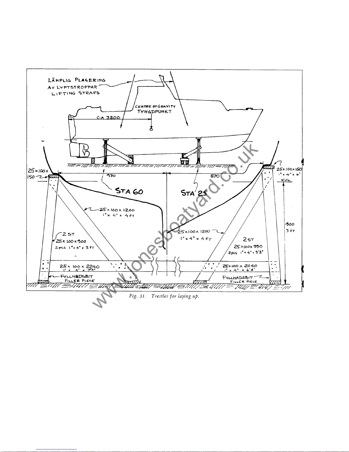
When stored for the winter your Albin 25 should stand on her cradleorhave blocks
under the keel and shores fore and aft, see fig.
31.
Other methods can be used, study
boats stored locally.
A winter cover can be anything from a complete boathouse to a simple cover, the
same as used when the boat was delivered. It needs a couple of supports to prevent
it from sagging down at the doghouse
or
in the centre of the cockpit.
Before covering up, all loose equipment should be removed and the boat cleaned
thoroughly.
To
avoid damages from freezing you must pay attention to a number of
things:
1.
2. Remove batteries,
3.
4.
5.
6.
Note: Check gear and decide if anything has to be repaired or replaced. In spring all
yards and boat firms have a lot to do. T he earlier you can order work or replacements
the more certain you can be of getting things done the way you want.
Winterize the engine (see engine chapter).
Open the bottom plug to drain bilge water.
Pump ou t and drain th e toilet.
Empty the watertank (pump
or
loosen hose at foot pump).
Clean bilges and be sure not to leave any water.
25
www.jonesboatyard.co.uk
Page 27
Spring commissioning includes:
1.
Cleaning deck and hull.
2.
Painting bottom.
3.
Oiling teak parts.
4.
5.
Waxing and polishing plastic surfaces.
Engine and gear should be checked and adjusted.
Tie her
up
right
Fenders
The plastic models which can be blown up with air are very good.
A size
of at least
10 cmx40 cm (4"~16'') will give adequate protection if
3
are used on each side.
Make them fast with a bowline o r a round turn and two half hitches. Fenders should
be put out when arriving at the quay and taken in as the mooring is left. Never have
the fenders out when underway.
Lines
Suitable material for mooring lines and anchor lines are polyester(Terylene, Dacron),
polyamid (Nylon, Perlon) a n d polypropylene. For an anchor line long fibre Polyamid
is best, Polypropylene is least expensive. Between the anchor line and the anchor
you should use
2
to3metres of chain.
Polypropylene is suitable and economical for use as mooring lines bu t the diameter
used should be larger than a polyester or polyamid.
A
lighter line of 8 mm diametre
would be heavy enough for temporary mooring.
A
large eyesplice in one end
of
the
26
www.jonesboatyard.co.uk
Page 28
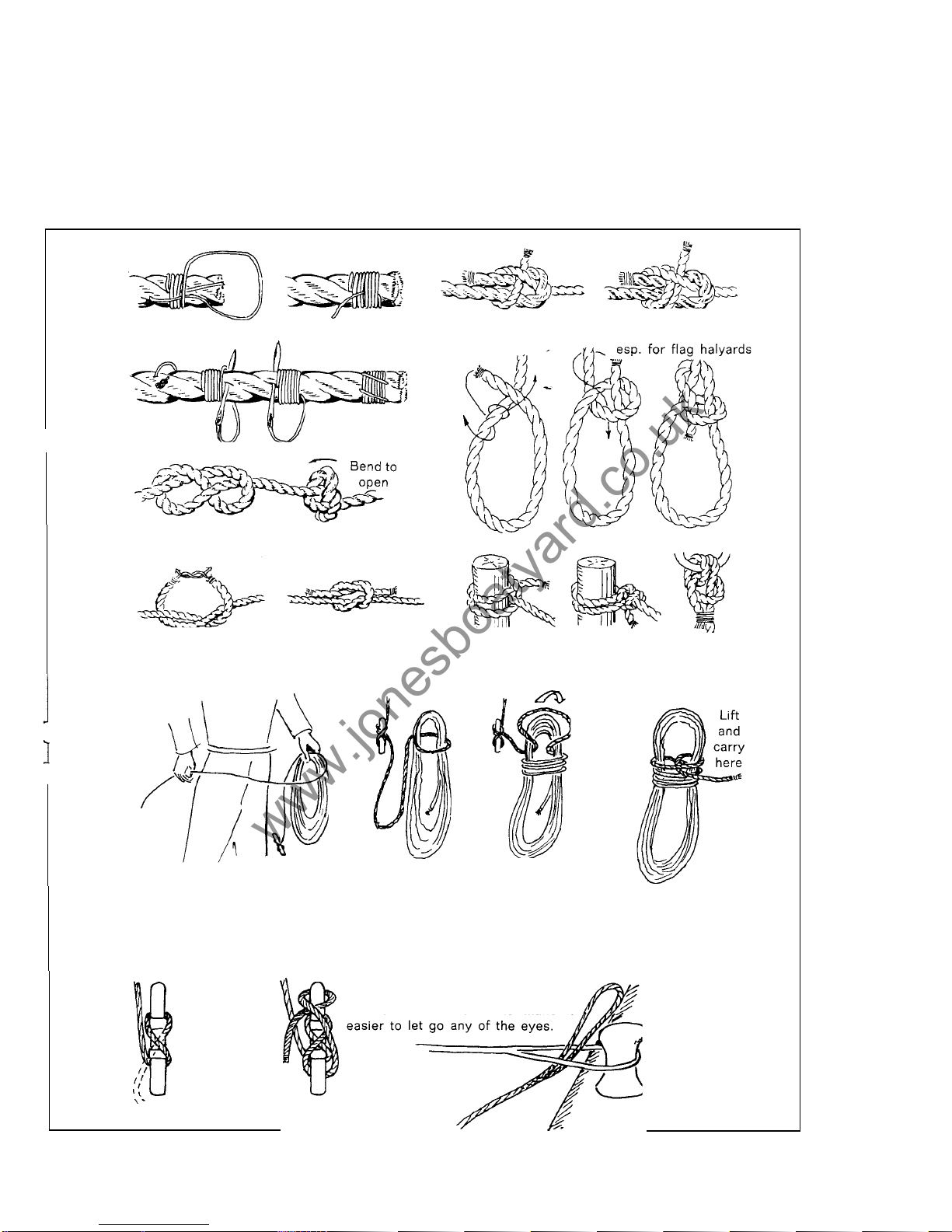
mooring line is convenient. Permanent mooring lines should be at least 18to20mm
in diametre of either polyester or polyamid. In difficult or dangerous places the diametre should be increased. Lines that are no t used should be stowed in a cool dry
place, out of direct sunlight. A piece of plastic tube slipped over the mooring lines
where they pass through fairleads, etc., will prevent chafe at that point. Never tie
up
so
that a line can chafe against sharp corners as they are easily worn through.
Before synthetic rope is cut, bind or tape where the cut will b e then singe the ends
in a flame. This will melt the fibres together and prevent the rope from unraveling.
Common whipping
Palm an d needle
wipping
Figure of eight knot used to stop the ends of
sheets to run through blocks
Sheet bend used
to
join
Double sheetbend holds
better than single bend
two lines
Bowline
-
fo rmakingan eye
Clove hitch A round turn Fishermans bend
around a bit and half hitches fo r bending cable
to anchor
-
also
used without seizing
easier to undo
Reef knot used only on light lines and yarn
When coiling a rope start from
The coiled rope is
the end which is made fast to
avoid unnessecary turns. which is bent over can be
"
locked
"
locked with a bight
the coil. like this.
An unattached rope
A half hitch is Put the eye up through the eye of a
used to lock the
mooring line which is already placed
line on a cleat around the bollard
-
to make
it
-
after a suffi
cient number of
turns (more if the
rope is slippery).
Fig.
32.
Knots.
coiling a
rope,
making fa
st
to a cleat.
27
www.jonesboatyard.co.uk
Page 29
Mooring
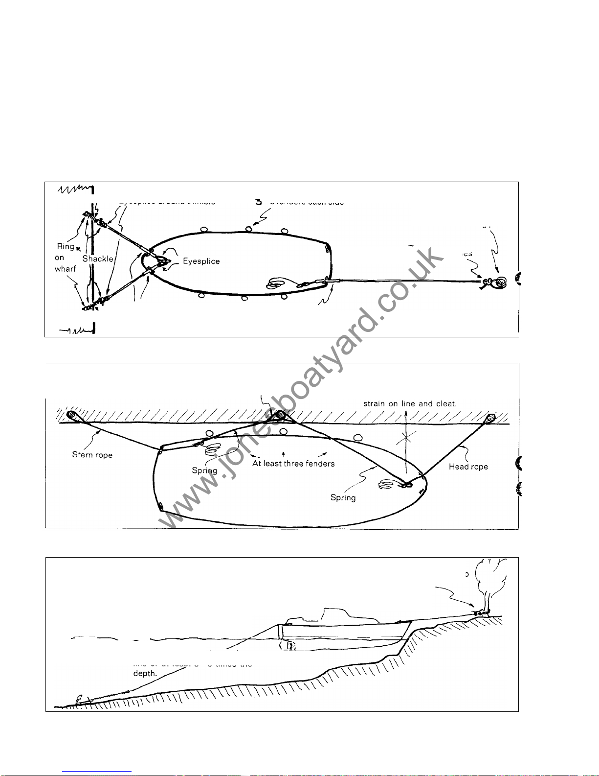
Synthetic lines are very slipperysothe mooring lines must be tied very carefully. The
knots you use must not slip yet must be easily untied. The methods and the knots
shown here fill these requirements.
For
tying up the following knots are best:
1.
Bowline
2.
3.
Always leave some slack in your mooring lines to allow for variations in water level
or motion caused b y wash from passing boats. Make fast the end
of
line on shore
and make fast on the cleat on deck
so
that the part of the line that is not needed is
on board.
Fig.
33-35
may give some ideas about the proper way to moor a boat.
Round turn and two half hitches.
Fishermans bend with
a
half hitch.
Spring Eyesplice around thimble
3
fenders eachside
Mooring post
A round turn and tw o half hitch
Plastic tube against chafe at fairleads
Mooring post
round
turn
and
two
half
hitches
I
Spring
Fig.
33.
Permanent m
ooring
(example)
I
If springs are used thepositioncan
be controled better.
Mooring straight in puts large
Fig.
34.
Mooring
alongside a quay.
Bowline or round turn and two
half hitches.
Approach slowly. drop anchor rather far
out (not more than th e length of the anchor
line). Speed can be checked with the
anchor line
-
if needed use a round turn
around the cleat.
Allow a scopeofthe anchorline of at least
3-5
times t he
Fig.
3J.
Temporary mooring
with
the stem against the shore
or
a wharf.
28
www.jonesboatyard.co.uk
Page 30
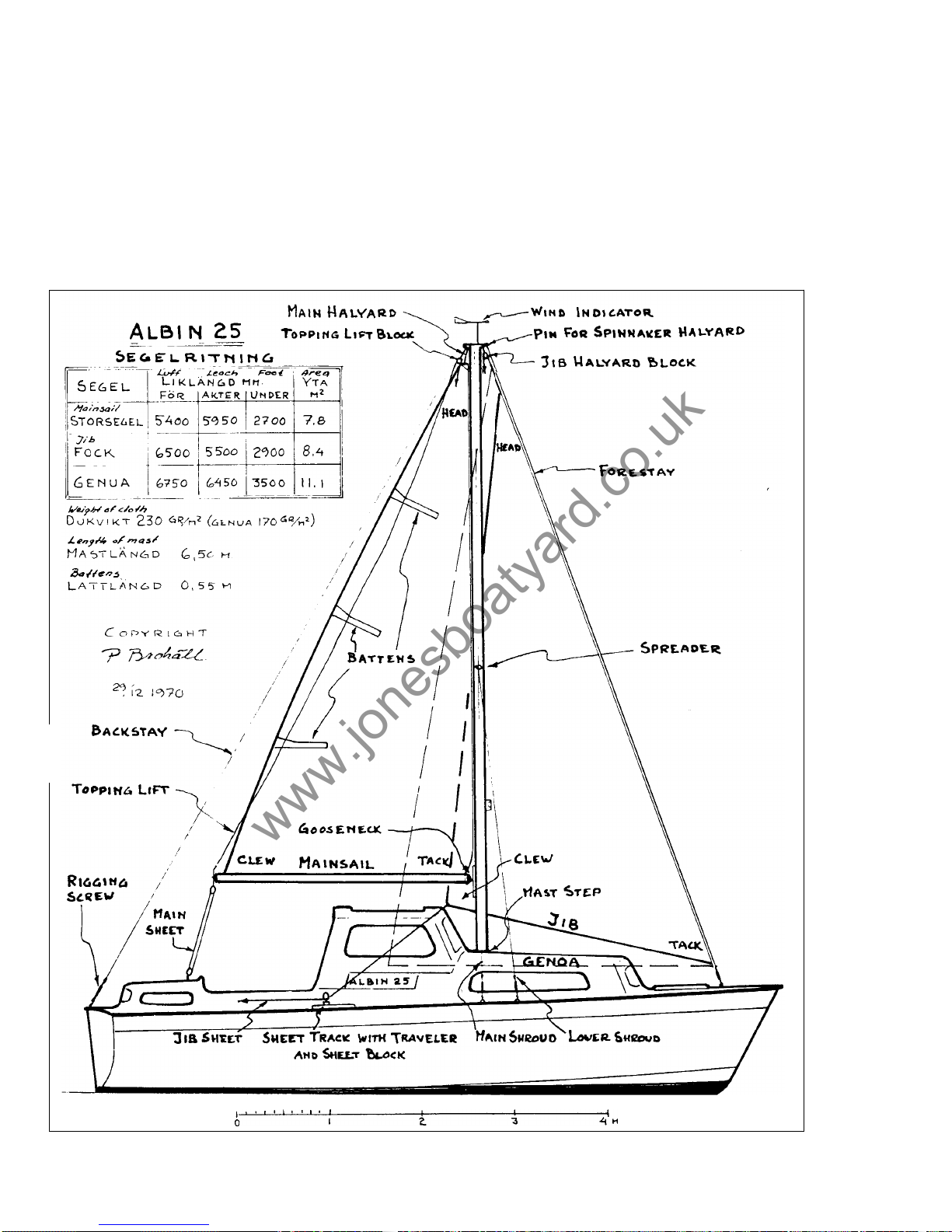
ALBIN
25
with
sails
The commercial fishermen have been using a steadying sail in all weather fo r years.
To
this end a suitable rig for the Albin25has been requested b y many owners. The
reasons being to give the boat easier movements in a seaway, to b e able to sail with
the engine shut off when the wind is fair and t o have a certain degree o f safety if the
engine should fail (plastic bags, lines, nets in propeller). The r ig that has been de
signed and tested for the Albin25does not make the boat into a real motorsailor
(that is a boat which is as good a sailboat as a motorboat). The boat remains a motor
boat with sails. This is because the keel area is too small to stop drift when sailing
or beating to windward. Because of this a fairly small sail area has been chosen, bu t
much more than steading sails and large enough to give fair sailing and increased
safety. The stability of the boat would allow a lot more sail - see the stability curve.
T
he
rig has been dimensioned to take hard weather b ut the rudder area is too small
to
allow a lot of sail in fresh winds and give safe manoeuvring'at the same time. The
Fig.
36.
Sail
plan.
29
www.jonesboatyard.co.uk
Page 31
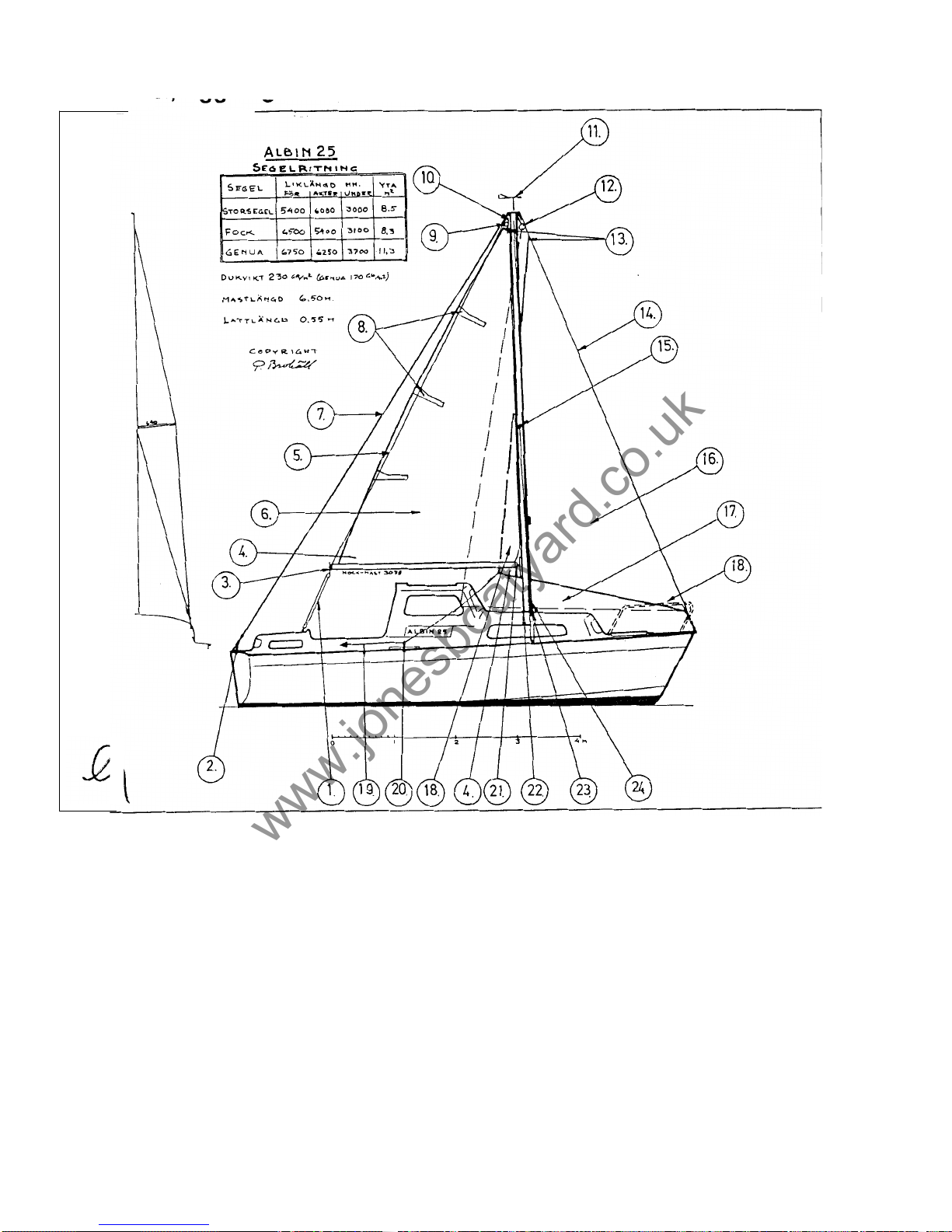
ALBIN
25
de Luxe
med segel, riggning
I
Fig.
12.
1.
Storskot
2.
Vantskruv
3.
Bomnockbeslag
4.
Skothorn
5.
Dirk
6.
Storsegel
7.
Akterstag
8.
Lattor
9.
10.
11.
12.
13.
14.
15.
16.
Dirkblock
Storfall
Vindvisare (Windex)
Fockfall med block
Fallhorn
Forstag
Vantspridare
Fock
17.
Genua
18.
Halshorn
19.
Fockskot
20.
21.
Bombeslag
22.
Mastfot
23.
Undervant
24.
Toppvant
Skotskena m
ed travare och skotblock
Manga har framstallt onskemal om en lamplig segelutrust- Den rigg som har provats ut och som kan kopas extra till
ning for
ALBlN
25
de Luxe och motiven har varit att fa stott-
ALBIN
25
de Luxe gor inte baten till en riktig motorseglare
ning av segel vid sjogang, att kunna segla med avstangd (en bat som ar lika bra segelbat som motorbat) utan det
motor nar vinden ar formanlig och att
fa
en okad sakerhet forblir en motorbat med segel. Detta beror pa att kolpartiet
om motornskulle krangla eller propellernbl i intrasslad
i
nat ar for Met for att hindra avdriften tillrackligt bra pa kryss.
eller plastpasar.
Darfor har en ganska blygsam segelyta valts
-
dock betyd-
32 B
www.jonesboatyard.co.uk
Page 32
sailing performance is good enough for you to beat against the wind in normal hnditions. You can sail around 70 degrees from the wind. B ut to turn through the eye of
the wind is almost impossible. Instead
it
is necessary to turn with the wind
-
a
con
-
trolled gybe. With the wind from the side o r from astern the boat performs fairly well.
In a ten knot wind the speed is around
4
knots and in a fresher wind she sails still
faster. O n long cruises, especially in open water, the sails certainly add safety be
-
cause they give the possibility if need be to maintain a course and avoid drifting down
onto a lee shore.
Fitting the rigging details
Sheet tracks and fittings for shrouds, stays and main sheet need holes according to
the drawing (fig.
37).
Fittings through foredeck and aft cabin t op must be madewater
tight with elastic putty. When nuts have been tightened (do not forget washers) lock
them through deforming the threads with a chisel or something similar.
A t the mast step the deck has to be strengthened t o be able to stand up to the pres
-
sure. Bore 6 holes according to the drawing (diametre
3/4''- l'')
through the outer
layer of the deck. Remove the Divinycell (core material) in and around the holes and
,
fill with a two-part polyester putty to get a pressure-proof filling.
Between the top wooden chock and the deck an elastic filler should be used. The
strengthening knee below the deck is fastened with two bolts through the glassfibre
"
bulkhead"with a mahogany"washer"on the outside. The stainless steel mast step
is fastened with wood screws. A
10
mm diametre hole is bored through deck and
wooden chocks to take the electric cable to the mast light.
A
plastic tube is fitted
watertight in the hole with elastic putty, the upper
end at least 1/2 inch above deck.
Through this tube t
he cable is lead from the electrical connection (aft of toilet) up
above deck and fitted with suitable connectors for the cable in the mast.
Riggning
(See fig.
36)
The standing and running rigging are labelled. The rigging procedure is as follows:
1.
Place th e mast on tw o boxesortrestles.
2.
The soft eye on the ji b halyard, the end without the snapshackle, is put through
the jib halyard block. The rope tail is then attached to the wire halyard
so
that the
30
www.jonesboatyard.co.uk
Page 33
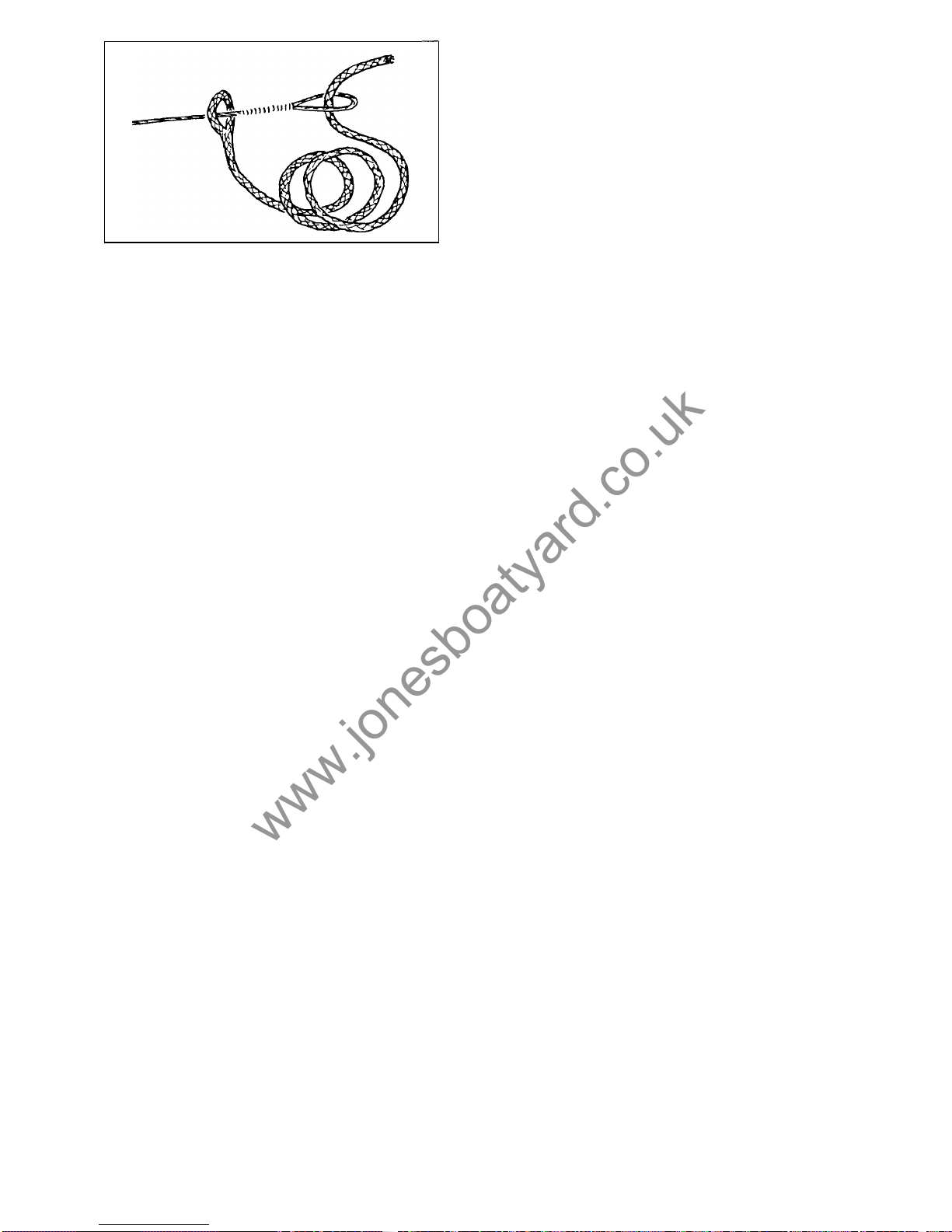
two form a reef knot, fig. 38. The block is then
shackled to the aft pin on the forward side of the
mast head fitting.
The eye of the main halyard is fed over the sheaves
of the mast head and the rope tail is attached as on
the jib halyard. The rope tail should be on the for
-
ward side of the mast.
4.
The lower shrouds are fixed to their respective
3.
tangs.
The main shrouds are attached.
The forestay is attached to the
middle hole on the
5.
6.
Fig.
38.
How
to connect the
rope
tail
to
the w
ire
halyard.
forward side of the mast head fitting. The forward
7.
8.
9.
11.
12.
13.
14.
15.
16.
hole is for a spinnaker halyard block.
The block for the topping lift is fixed to the inner hole on the aft side of the mast.
The block should be turned
so
that the rope end leads down the mast.
The back stay i s fixed in the aft hole
The locking pins on the rigging screws ar e removed and the bolts must be taken
out. The rigging screws should be opened half way and then attached to their
respective stays and shrouds, All rigging screws should b e fitted
so
that they
turn the same way when tightened.
The straps on the spreader ends are loosened. One split pin and washer are
removed from the spreader, the spreader tube is put through the hole in the
mast and the washer and split pin are fitted again. The main shrouds are put
into the grooves of the spreader and the straps are replaced. Tape or cover the
ends to prevent the sails from chafing on sharp edges.
Attach wind indicator or burgee.
Check that all bolts in the rigging are locked with split pins and all shackles are
siezed with wire. Tape over the sharp ends
of
pins.
Position the mast with the strap hook at the foot against the athwarthship bolt
of the mast step.
Connect the mast cables from the steaming light to the connectors
at
the mast
step.
Attach the forestay and shrouds. The mast is raised by hand and the backstay
is attached. Tighten the rigging and lock the rigging screws. The lower shrouds
should b e tightened lightly but the others should be tightened fairly hard. After
sailing fo r some time the rigging should be tightened again. Tape the pins and
the rigging screws.
Boom and main sheet should then b e fixed. The locking knob on the gooseneck
traveler should be below the boom.
Setting sail for the first time
Pull the mainsail out on the boom and attach it to the gooseneck fitting.
Pull
the sail
out tight. Fit the slides into the mast track, insert the battens in the batten pockets
in the mainsail and attach the main halyard. Hoist the mainsail almost t o the top
of
the mast. The luff can then be tensioned the desired amount by pushing the boom
down and locking it there with the knob. Both the foot and luff should be stretched
just enough t o make the small wrinkles in the sail disappear but not
so
hard that
diagonal wrinkles appear.
Hoist the jib and tension the halyard as much as possible. The blocks for thejib sheet
leads should be adjusted on the tracks
so
that the line of the sheet i s below a line
perpendicular to the forestay. The sheeting points must of course b e adjusted
so
that
the leech is neither too slack nor too tight. If the jib is hoisted higher with a couple
of shackles between the tack and tack fitting, the sheet point moves aft.
As
a rule,
it is better to have the leech too slack if anything. The positions of the sheeting points
should be marked on the track with paint or tape.
It is advi
sable
to
tape the forward
ends of the track
so
that the sheet block slides cannot come off b y mistake and be
lost.
Avoid heeling the Albin 25 too much and shorten sail in good time. Begin by reefing
the mainsail. If the boom
is
pulled aft from the fitting the sail can be rolled round the
boom (easier to do with sail lowered). Naturally the easiest way to shorten sail is to
lower one of the sails.
31
www.jonesboatyard.co.uk
Page 34

Sails and maintenance
Modern sails o f polyester fiber (terylene, dacron) do not have t o b e streched and
worked in. Provided they are not subjectedto abnormal forces, they will keep theform
given b y the sailmaker. Consequently, one can just hoist a suit o f new sails and sail
away. Sails, however, d o require some maintenance. What spoils the sails is chafing,
too much flogging, over stretching, wrinkles, moisture, dirt, salt, mildew and direct
exposure to the sun. Some parts of the sail are more vunerable to chafe than others.
The head and clew, batten pockets, the luff and foot where pulled into the mast and
boom are particularly exposed. The parts of the sails which come into contact with the
spreaders and shrouds are particularly liable t o be damaged. Modern synthetic sail
cloth is much stronger than cotton and not so soft which means that the stitching
does not sink into the cloth as it does on cotton sails.
This means that the stiching is exposed and likely to be chafed.
It
is
necessary to
check the seams an d t o carry out repairs before the damage becomes to o extensive.
Temporary repairs can be made with tape. Flogging spoils the sails and should be
avoided. W e t sails should be dried by spreading them out in the sun and only in a
very light wind should they b e hoisted t o dry.
Wrinkles make the sails less effective. Sails should, therefore, not be stuffed into
bags which are t oo small. It
is
best to fold sails parallel to the foot and then to roll
them loosely around the luff. A sail must of course be dry before being bagged.
It
is
easiest t o detect the presence of moisture b y feeling the tack. Dirt and mildew may
not damage a sail but they
look
unsightly. Salt makes sails heavier and it also attracts
moisture which will make them heavier still. Salt is best removed by hosing the sail
with fresh water.
Polyester fibres are resistent t o sun but age faster if exposed to too much sun. P ro
tect the mainsail with a cover when it is left on the boom or remove it from the boom
and take it below. Dirty sails can be washed in luke warm water and a mild detergent.
If
the sail is too big to be rinsed in abath tub, spread iton a floor, hose it with fresh
water and scrub it with a soft brush. Grease can be removed with trichlorethylene.
In winter the sails should be clean and dry and folded loosely in their bags. They
should be stored in a dry, well ventilated place.
More general advice
A line between the handrails of the aft cabin can make it easy fo r someone to climb
on board up the footsteps o n the transom.
A
foot stool of the right height can makeitmore comfortable at the helm on a long
run.
The interior accommodation can be improved with hooks, plastic bins etc., fitted
according t o your ow n needs.
Nets called donkey hammocks slung under the roof of the aft cabin can give extra
stowage fo r clothes, etc.
Try t o plan regular safety exercises such as man overboard drill, fire drill and what
you would do in case
of
collision, fog, storm, engine trouble, etc.
A t least one person besides yourself should be able to handlethe boat in case some
-
thing should happen to you.
32
www.jonesboatyard.co.uk
 Loading...