


Pequea Turbo Tedder
Model TT8101
Operator’s Manual
THIS MANUAL MUST BE READ AND UNDERSTOOD BEFORE ANYONE OPERATES THIS MACHINE!
Manual# 990134
Revised 05/5/2017

YOU MUST FILL OUT YOUR WARRANTY REGISTRATION
TO ACTIVATE YOUR WARRANTY AND TO QUALIFY FOR
PARTS AND SERVICE!!
To the Owner;
Thank-You for choosing a quality product from Pequea Machine, Inc. We
strive to give you the best equipment and the best level of service of any
company. With a little care and maintenance this machine will do your work
for you for many years. In this manual, we make an effort to get you better
acquainted with the machine so you can achieve maximum performance. We
design and build all of our equipment with the end user in mind so we welcome any suggestions or ideas for improvement. Please note that it is within
our rights to make changes or improvements to our equipment without updating the equipment that was manufactured before the change took place.
Please take a few minutes to ll out the area below. This information will be
valuable to you when ordering parts or requesting service from your dealer.
Dealer Name:_____________________________
Dealer Phone Number:______________________
Service Manager/Technician:_________________
Model# and Description:_____________________
Serial Number:____________________________
Date of Purchase:__________________________
2

TABLE OF CONTENTS
Introduction ……………………………………………………………… 2
Intended Use ………………………………………………… 2
Serial Number …………………………………………….… 2
Specications ………………………………………………… 2
Safety …………………………………………………………………….… 3
Power Source Safety ………………………………………… 3
Safety Decals and Reectors ……………………………… 4
Hitching …………………………………………………………………… 5
Attaching to the Tractor ……………………………………… 5
Transporting ……………………………………………………………… 6
Field Transport ……………………………………………… 6
Road Transport ……………………………………………… 6
Field Set-up ……………………………………………………………… 7
Tine Height Adjustment …………………………………… 7
Adjustments ……………………………………………………………… 8
Tine Pitch Adjustment ……………………..……………… 8
Axle Adjustments ………………………………………….. 9
General Operation …………………………………………………… 10
Folding for Transport ……………………………………… 11
Lubrication and Maintenance …………………………………… 12
Gearbox Lubrication ………………………………………… 12
General Lubrication ……………………………………… 12
Grease Fitting Lubrication ………………………………… 12
PTO Lubrication …………………………………………… 15
Electrical ………………………………………………………………… 16
Technical ………………………………………………………………… 17
Replacing the Flotation Springs …………………………… 17
Troubleshooting ……………………………………………………… 18
Warranty …………………………………………………………………… 19
1

INTRODUCTION
Intended Use
The Pequea TurboTedders are designed for evenly distributing and drying hay crops only. Pequea
will not cover under warranty a tedder that has been used outside of these crops.
Serial Number
The tedder’s serial number can be found on the
tongue directly under the driveline. Please use
this number when requesting service, seeking
information, or ordering parts. For the operator’s
convenience, space to record the serial number,
model number, purchase date, and dealer has
been provided inside the front cover of this manual.
Specications
Specications TT4100 TT6100 TT8101
Working Width 18' 2" 26’ 6” 35’
Transport Width 9’ 2” 11’ 6” 11’ 6”
Gearboxes Grease/Oil Bath Grease/Oil Bath Grease/Oil Bath
Rotors 4 6 8
Arms Per Rotor 7 7 7
Arm Construction Round Tubular Round Tubular Round Tubular
PTO/HP Recommended 35+ 55+ 75+
Spindle Size 1-3/8” 1-3/8” 1-3/8”
Hub 4-Bolt w/ Tapered Bearings 4-Bolt w/ Tapered Bearings 4-Bolt w/ Tapered Bearings
Wheels 4-Bolt Heavy Duty, Painted 4-Bolt Heavy Duty, Painted 4-Bolt Heavy Duty, Painted
Transport Wheels
Tires 18.5 x 8 18.5 x 8 18.5 x 8
Hydraulic Requirement 1000psi 1200psi 1900psi
N/A 7.5-10 LR E Tires 7.5-10 LR E Tires
2

SAFETY
This symbol precedes specic safety instructions throughout this manual. When reading the manual, pay close attention to the information that follows this symbol.
FAILURE TO FOLLOW INSTRUCTIONS IN THIS MANUAL COULD RESULT IN PERSONAL
INJURY OR DEATH. READ ENTIRE MANUAL BEFORE OPERATING THE TEDDER.
Keep hands, feet and clothing away from the machine’s power take-off (PTO) shaft and any
other moving parts until the machine has been shut down and the power source has been
locked out.
Do not adjust, unclog, lubricate, or service the tedder until it has been shut down.
Support the tedder securely while working under it.
Be certain all bystanders and animals are a safe distance away before folding or unfolding
the tedder.
!!SAFETY FIRST!!
Never allow anyone to ride on the tractor or the tedder.
Before transporting, make sure hands-free transport lock is latched in place.
When transporting, never exceed a speed of 25 MPH and avoid sudden turns.
Be constantly aware of the ends of the machine to avoid collision with other objects.
When transporting the machine on public roads use the proper reectors, lights, and slow
moving vehicle signs required by local government agencies. Pequea will not be liable for any
trafc violations.
Be sure to check all fasteners before and after every use, this is especially important when
the tedder is new but is a good practice on any machinery with high vibration levels.
Be careful around hydraulic hoses and ttings. Never go near hydraulic leaks. High pressure
leaks can puncture skin and cause serious injury or death!
Power Source Safety
Do not use a PTO shaft without a rotating shield in good working order. Make sure drive system safety shields are in place on both the tractor and the tedder.
Do not overextend the PTO Shaft
PTO shield chains must be attached to the tractor and/or the tedder to keep the shield from
rotating.
3

SAFETY
Safety Decals and Reectors
Safety decals and reectors are for the safety of yourself and others, and must be heeded at all
times. If any decals are missing, faded, or damaged in any way, please contact your dealer for
replacements immediately. Shown below are some of the decals used on your tedder.
4
HITCHING
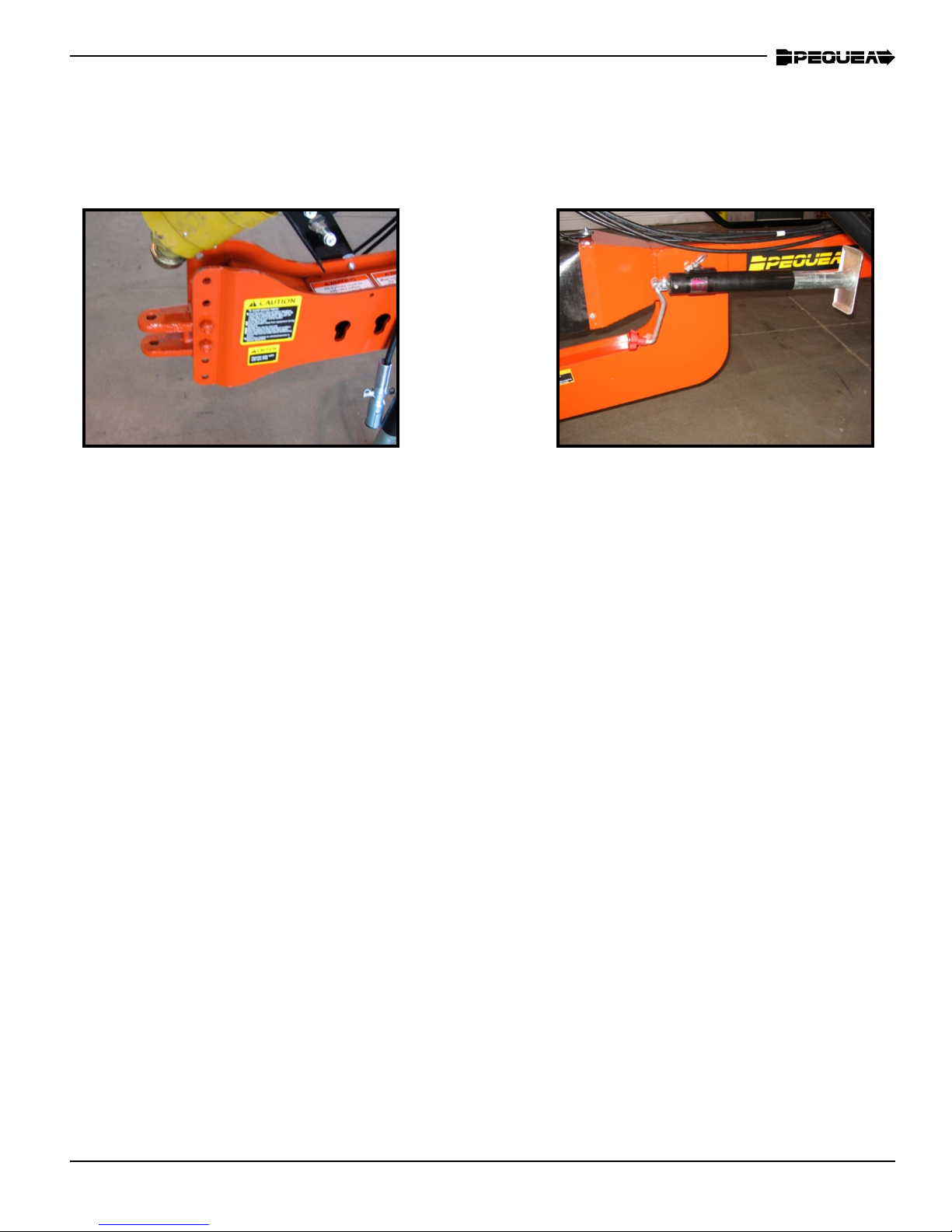
Attaching to the Tractor
Figure 1
Crank the jack up or down to align the tractor draw bar with the hitch.
The tedder hitch is bolted on and can be adjusted up or down to accommodate various drawbar
heights (Figure 1). Select a height that keeps the tedder chassis level when it is connected to
the tractor.
When attaching to the draw bar always use a draw bar pin with a safety clip to ensure that the
tedder doesn’t bounce off of the tractor.
After attaching the tedder, crank the jack down until all the weight rests on the tractor drawbar,
then remove the jack and place it in the transport position. (Figure 2)
Attach the PTO shaft to the tractor. Make sure the locking balls in the splined coupling are
operational and that the PTO shaft locks securely on the tractor output shaft. NOTE: Be sure to
push the PTO stand down against the tongue to avoid damage to the PTO shaft shielding.
The TT8101 is equipped with hydraulic cylinders to fold the machine for transport. The hoses
should be connected to a double acting valve at the rear of the tractor. The slotted holes on the
side of the tongue (Figure 1) are storage holes for the hoses
Figure 2
Connect the wiring plug from the tedder into the female plug end on the tractor. If your tractor
is not equipped with this plug you will need to have it installed by your dealer. Never travel on
public roads without proper lighting.
5
TRANSPORTING
Field Transport
Never allow any riders on the tractor or the tedder.
Remain fully aware of the width of the tedder in relation to objects you are passing.
Never travel at speeds of more than 12 MPH in the eld.
Road Transport
Adhere the suggestions for eld transport listed above.
Make sure the hands-free transport lock is latched in place properly (shown in Figure 13).
ALWAYS FOLLOW LOCAL TRAFFIC LAWS IN REGARDS TO THE TRANSPORTING OF FARM
EQUIPMENT. PEQUEA WILL NOT BE HELD LIABLE FOR FINES INCURRED DUE TO TRAFFIC VIOLATIONS.
Do not exceed 25 MPH on any public road. Excessive speeds combined with common road obstructions can cause failures.
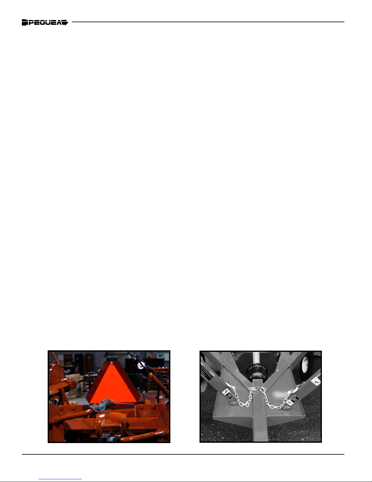
Be sure the SMV (slow moving vehicle) Symbol is visible from the rear of the machine as shown
in Figure 3.
Keep a close eye on the tedder wings when transporting on the road or in the eld. A leaky valve
in the tractor’s hydraulic system will cause the tedder to slowly unfold. If this occurs, you will want
to disconnect the hydraulics before transporting. Figure 4 shows the wings supported properly for
transport and the safety chains attached.
Be sure to use the lights when traveling on the road at night.
Figure 3
Figure 4
6

FIELD SET UP
To lower the tedder into tedding position engage the hydraulics for the tilt cylinder rst to raise the
wings off of the chassis then engage the main hydraulics to unfold the wings. Be sure that nobody
is around the tedder or the tractor as the wings are lowering. The tines and arms can cause serious
injury to anybody that it comes into contact with. Make sure that the hitch is attached to the tractor
and the pin is installed when the wings are lowering. If the hitch is not properly attached to the tractor, the weight of the rotors when it is unfolding could cause the hitch to whip up causing serious
personal injury or damage to equipment.
NEVER RUN THE PTO WHILE THE TEDDER IS IN THE TRANSPORT POSITION! THIS CAN CAUSE DAMAGE TO THE JOINTS
AND ALSO POSES A PERSONAL INJURY HAZARD.
The tine height adjustments can be made by turning the handle shown in Figure 6.
Turn the handle clockwise to raise the tine height.
Turn the handle counter clockwise to lower the tine height.
Generally, the tines should be around 1-2 inches from the ground for most crops. However, the
stubble length or crop moisture content can change where the optimum setting will be.
IT IS UP TO THE OPERATOR TO DETERMINE WHAT THE BEST POSITION SHOULD BE.
1-2”
Figure 5 Figure 6
DO NOT ADJUST THE TEDDER UNLESS THE TRACTOR IS OFF AND THE PTO SHAFT
IS DISCONNECTED. ALWAYS ADJUST THE MACHINE BY YOURSELF. A SECOND
PERSON INCREASES THE CHANCE OF AN ACCIDENT.
7

ADJUSTMENTS
Tine Pitch Adjustments
Figure 7
Figure 8
The tine pitch (the angle of the tine in relation to the tine arm) can be adjusted by reversing the eccentric spacer washer. The spacer position in Figure 7
will give the tine a less aggressive position as shown in Figure 8.
The spacer position shown in Figure 9 will give the tine a more aggressive
position as shown in Figure 10.
A more aggressive tine position will throw the hay higher.
Figure 10Figure 9
8
ADJUSTMENTS
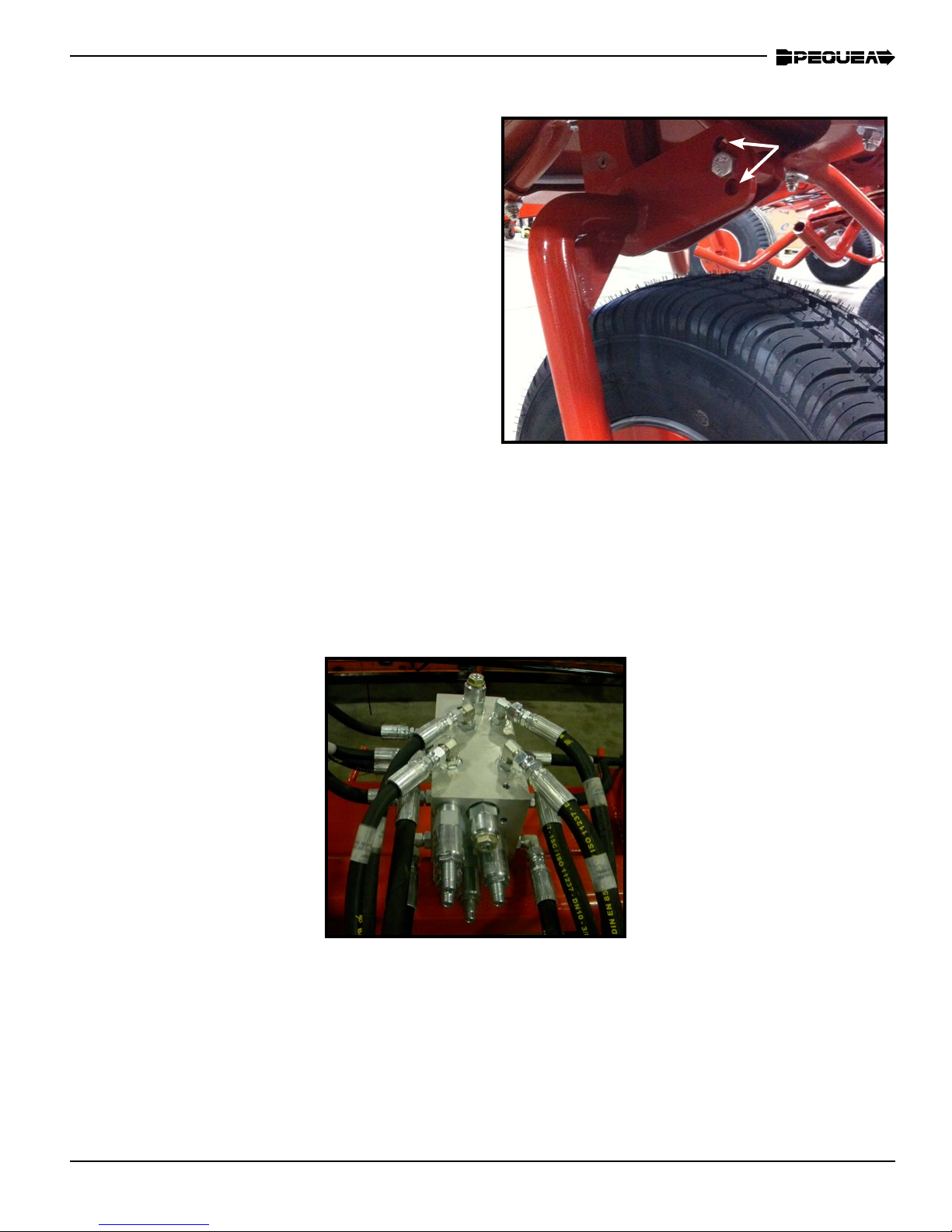
Axle Adjustments
The angle of the axles can be adjusted to raise or
lower the whole machine. This will allow you to tilt
the tedder forward more and get a more aggressive tedding action. The tedders are set at the factory to run in the less aggressive position (shown
at right). To adjust to the higher position you will
need to pick the tedder up off the ground using
a hoist or a lift. With the tedder in the transport
mode, remove the 1/2” bolt, pull the axle forward
to meet the second hole, and reinsert bolt. Repeat
for all axles.
Manifold Adjustments
Figure 11
9

GENERAL OPERATION
DO NOT BEGIN OPERATION UNTIL ALL OF THE SAFETY WARNINGS HAVE BEEN
READ AND UNDERSTOOD!
Once all of the adjustments and initial set up instructions have been followed and the proper
adjustments made, the tedder is ready to operate in the eld.
Connect the tedder PTO shaft to the tractor by pulling the spring collar back and sliding
the shaft yoke onto the 6 splined tractor PTO shaft. Slide the shaft forward until it stops and
then pull back slowly until the balls engage into the ball groove on the tractor shaft.
DO NOT RUN THE PTO UNLESS THE LOCKING BALLS ARE ENGAGED. THE SHAFT
COULD SLIDE OFF DURING OPERATION AND CAUSE SERIOUS INJURY OR DEATH.
The PTO speed should never exceed 540 rpm. Generally, 450 rpm and a 6 mph ground
speed is a comfortable operating setting. Crop conditions and eld conditions will ultimately
determine the settings for the tedder and the tractor.
10

Folding for Transport
Do not fold for transport unless the tedder is on even ground!
When tedding, the transport wheels can swivel and are spring loaded to support the weight of
the chassis. The springs will be compressed and the wheels locked in the straight position when
the tedder is folded up for transport. NOTE: Be sure to have the wheels relatively straight before
folding so the locks can engage properly! Figure 13 shows the transport lock properly engaged.
Do not transport the tedder until transport lock is latched in place as shown in Figure 14.
Figure 13
Figure 14
Transport lock
Transport Lock Engaged
11

LUBRICATION AND MAINTENANCE
NEVER PERFORM ROUTINE MAINTENANCE, REPAIRS OR INSPECTIONS ON ANY
PIECE OF EQUIPMENT UNLESS THE TRACTOR IS SHUT OFF AND DISCONNECTED
FROM THE MACHINE.
IT IS ALWAYS BETTER TO WORK WITH ANOTHER PERSON WHEN MAINTAINING OR
SERVICING A PIECE OF EQUIPMENT. ACCIDENTS CAN BE PREVENTED AND HELP
CAN BE ATTAINED EASIER WHEN ANOTHER PERSON IS AVAILABLE TO HELP.
Gearbox Lubrication
OIL FILL PLUG
OIL DRAIN PLUG
Figure 15
The oil in the center gearbox should be drained out and replaced every year. When relling the
gearbox, remove the ll plug and ll up to the ll hole using 80W-90 gear oil. Check the oil level
periodically throughout the season to insure that it remains full at all times.
Be sure to properly dispose of any used oil or grease! Do not pour directly onto the ground!
12

LUBRICATION AND MAINTENANCE
The rotor gearboxes (Figure 16) have been packed
with grease at the factory and should not need to be
maintained. However, they should be checked before
each season to make sure the gears are still coated
with a lm of grease. If additional grease is needed,
use several ounces of NLGI #2 gear grease.
Figure 16
The grease in the rotor gearboxes can seep out as the spindle exes. Do not be alarmed,
this is normal. The seal is exible, so when the spindle exes it can cause a small gap which
allows oil to seep out between the seal and the spindle assembly.
General Lubrication
When a grease point has specic hourly frequency, 1 full pump should be sufcient lubrication. Always use a grease that is rated for high temperatures commonly found in a bearing.
All of the pivot points have a grease
tting and a bronze bushing. This
should always be visibly wet with
grease. Grease as needed.
Figure 17
The cylinder nut should always be
visually wet with grease. Grease as
needed.
Figure 18
13

General Lubrication cont.
Several of the nger joint assemblies
are equipped with grease ttings
(these are the 8 bearings closest to
the center of the tedder). These can
be accessed through the slots cut
out of the rubber pads as each pivot.
Grease periodically. The outside joint
bearings (4 bearings) are sealed and
contain no grease ttings.
The lifting carriage assembly
has a grease pin at each pivot
(four total) including one under
the front tilt cylinder (shown bottom right).
14

LUBRICATION AND MAINTENANCE
PTO Shaft Lubrication
The radial pin clutch and the center
cross in the PTO yokes should be
greased every 8 hours.
The plastic PTO shielding should be
lubricated at all times. If the shield
feels tight when it is extended and retracted then lubricate as necessary.
As is the case with any piece of new equipment, periodically check for loose
bolts and nuts. Paint and parts settling after the initial vibrations are common
and can cause bolts or nuts to loosen. Check the following parts frequently:
• Lug Bolts
• Tines & Tine Arms
• Guards
• Hydraulic Fittings
• All Fasteners
15
ELECTRICAL
1
2
3
4
7
6
5
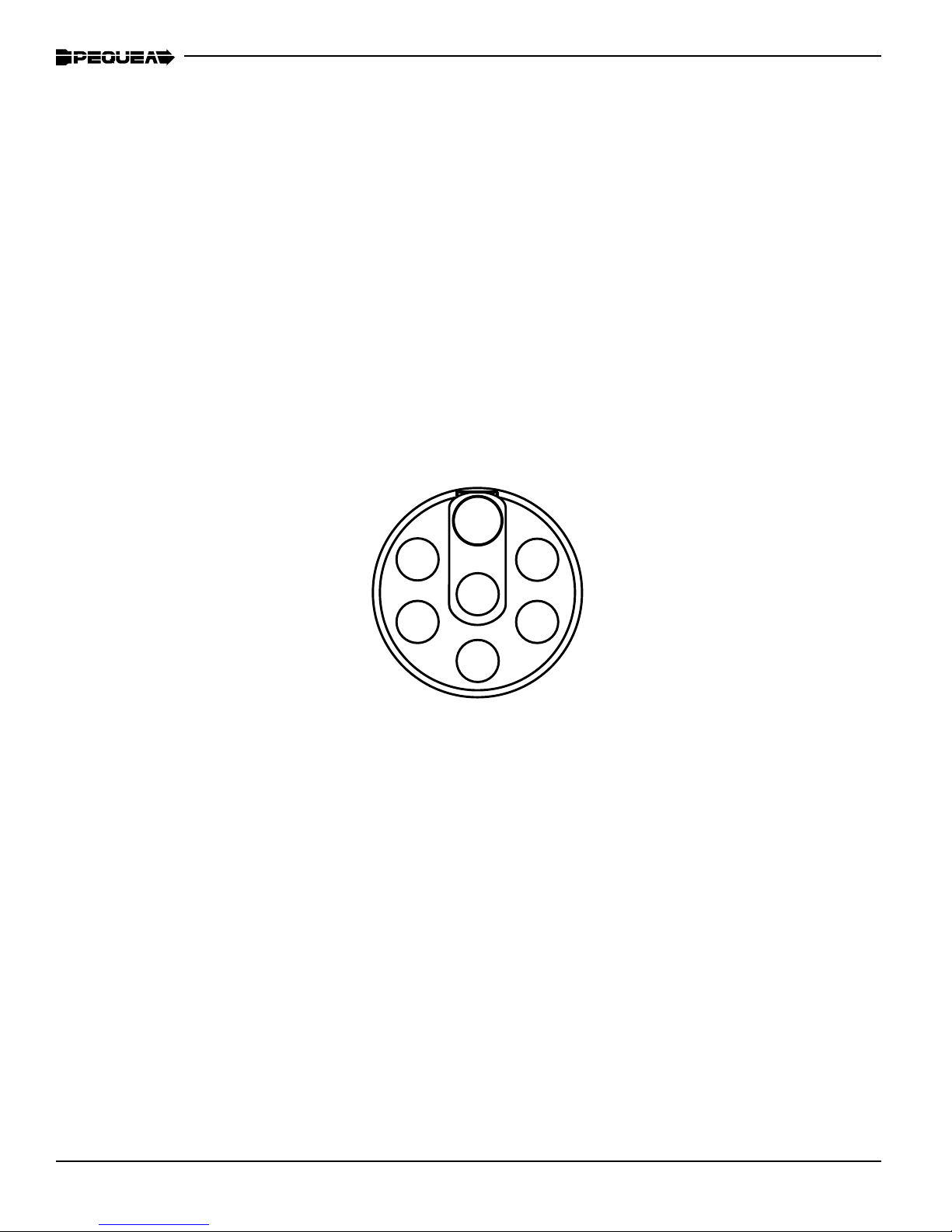
Your tedder is equipped with lights to be used when transporting on public roads. Make sure the wiring and the lights are kept fully functional at all times. Shown below is the wiring diagram for the 7-pin
connector plug and the color code used for all Pequea equipment and trailers. The drawing is shown
looking at the back side of the plug insert. NOTE: this is showing the full wiring schematic for this type
of plug. The tedder only uses four of these wires; #1, #3, #5, & #6.
Wiring Schematic for 7-Pin Wiring Plug
Position Function Wire Color
1 Ground White
2 Spare Circuit
3 Left Turn Signal Yellow
4 Auxiliary Red
5 Right Turn Signal Green
6 Running Lights Brown
7 Electric Brakes Black
16

TECHNICAL
Replacing the Flotation Springs
The otation springs are located inside the mounting stem of the transport wheels. (The large wheels
on the chassis). These wheels are also designed to carry the weight of the chassis when the tedder is
in the working mode. The springs may need to be replaced periodically if they become weakened and
no longer provide the desired amount of assistance. If so, follow the directions below to replace.
• Lift the tedder with a hoist or a lift to take all the weight off of the transport wheels.
• Use two clamps to hold the cap onto the spring tube.
• Remove the bolts from the cap and slowly release the clamps until the spring is fully extended
and there is no more force on the clamp.
Replace the spring and put the cap back on.
FAILURE TO FOLLOW THESE INSTRUCTIONS COULD RESULT IN PERSONAL INJURY AS A
RESULT OF THE CAP BEING LAUNCHED BY THE SPRING WHEN THE BOLTS ARE BEING REMOVED.
IMPORTANT: Raise tedder with lift or hoist and
apply clamping force to the cap while removing
the bolts.
17

TROUBLESHOOTING
Problem Possible Cause Solution
When folding up for transport, the
wings fold straight up all the way
before bottom cylinders extend to
land on the arms on the pad.
When folding up for transport, the
wings aren’t able to fold all the way
in before landing on the pad (the
bottom cylinders are too fast).
Relief Valve (RV1)
is set too high.
Relief Valve (RV1)
is set too low
Adjust the relief valve RV1 (see gure be-
low) by rotating CCW. Loosen Jam nut
and adjust with allen wrench. Be sure to
re-tighten jam nut after adjusting.
Adjust the relief valve RV1 (see gure
below) by rotating CW. Loosen Jam nut
and adjust with allen wrench. Be sure to
re-tighten jam nut after adjusting.
18

Pequea Machine’s Limited Warranty
Pequea Machine Company warrants to the original Purchaser all Machinery, Equipment, or Trailers manufactured by it, to be free from defects in material and workmanship under normal use and service. Its obligation
under this Warranty shall be limited to replacement or repair of any parts thereof, free of charge to the original
Purchaser, at its place of business, provided, however, that the part(s) to be replaced or repaired, shall within
one (1) year after delivery to the original Purchaser, be demonstrated to be defective; which determination
shall be made by the Company. The said components or parts must be returned through the Selling dealer or
distributor directly to the Company with all transportation charges prepaid. Notice of defect shall be furnished
in writing to the Seller and to the agent through whom the machinery was received, disclosing in full all known
defects and failure in operation and use, and reasonable time shall be given to the Seller to remedy any such
defects and failures. Failure to make such trial or give such notice shall be deemed an absolute acceptance
by the Buyer and satisfaction in full of this Limited Warranty.
This Warranty does not cover, under any circumstances, any parts, components, or materials which, in the
opinion of the Seller and Company, have been subjected to neglect, misuse, alteration, accident, or if repaired, with parts other than those manufactured by and obtained from Pequea Machine Company.
This Warranty does not cover components which are already covered by a separate Warranty provided by
the supplier of said parts or components. The Company’s obligation under this Warranty is limited to repair
or replacement, free of charge to the original Purchaser, of any part which in judgment of the Company is
defective. This Warranty does not cover normal wear and tear.
THIS WARRANTY IS MADE EXPRESSLY IN LIEU OF ALL OTHER WARRANTIES, EXPRESSED OR IMPLIED, INCLUDING ANY WARRANTY OF MERCHANTABILITY AND FITNESS FOR USE AND PURPOSE
AND OF ALL OTHER OBLIGATIONS OR LIABILITIES ON ITS PART AND ANY IMPLIED WARRANTY. AND
IT NEITHER ASSUMES NOR AUTHORIZES ANY OTHER LIABILITY IN CONNECTION WITH A SALE OF
THIS MACHINE. THIS WARRANTY SHALL NOT APPLY TO THIS MACHINE OR TO ANY PART THEREOF
WHICH HAS BEEN SUBJECT TO ACCIDENT, NEGLIGENCE, ALTERATION, ABUSE, OR MISUSE.
The Company makes no Warranty whatsoever in respect to accessories or parts not supplied by the Company. The term “original Purchaser” as used in this warranty, shall be deemed that person for whom the
Machine, Equipment, or Trailer is originally supplied. This Warranty shall apply only within the boundaries of
the continental United States.
Under this Warranty, the Company cannot guarantee that existing conditions beyond its control will not affect
its ability to obtain materials or manufacture necessary replacement parts.
No one is authorized to alter, modify, or change the terms of this Warranty in any manner.
The Company warrants the Construction of the equipment sold herein and will replace at its expense for a
period of (1) year from the date hereof, any parts which prove defective as determined under the terms of
this Limited Warranty.
Pequea Machine’s Extended Gearbox Warranty
In addition to its Limited Warranty (outlined above), Pequea Machine Company warrants the gearbox assem-
bly for all Turbo Tedder models (TT Series, excluding the following older models: TT4100, TT6100, TT6200,
TT8100) for a total period of ve (5) years from the date of purchase by the original purchaser as follows:
If the defect occurs within the rst ve (5) years, Pequea Machine will replace or repair the gearbox assembly.
The obligation of the Company shall be limited to replacing or repairing the gearbox assembly, at the option
of the Company. The Company shall not be responsible for any labor costs, or removal or reinstallation of
the gearbox assembly, or any transportation costs to or from its facility in New Holland, PA. The defective
gearbox assembly must be returned through the Selling dealer or distributor directly to the Company with all
transportation charges prepaid. If the customer prefers, they can expedite delivery of a replacement gearbox
assembly for a cost of $150.00 plus freight charges (price subject to change at discretion of Company). The
defective gearbox assembly must still be returned to the Company.
19

20

21

E-mail: pequea@pequeamachine.com
200 Jalyn Drive
P.O. Box 399
New Holland PA 17557
Phone: 717-354-4343
Fax: 717-354-8843
www.pequeamachine.com
 Loading...