

Page 1
FACTORY AUTOMATION
MANUAL
WCS-PG310
WCS PROFIBUS DP
Interface Module
Page 2

WCS-PG310
With regard to the supply of products, the current issue of the following document is ap-
plicable: The General Terms of Delivery for Products and Services of the Electrical Indus-
try, published by the Central Association of the Electrical Industry (Zentralverband
Elektrotechnik und Elektroindustrie (ZVEI) e.V.) in its most recent version as well as the
supplementary clause: "Expanded reservation of proprietorship"
Page 3

WCS-PG310
1 Introduction................................................................................. 4
1.1 Content of this Document ................................................................... 4
1.2 Target Group, Personnel...................................................................... 4
1.3 Symbols Used ...................................................................................... 4
2 Product Description ................................................................... 6
2.1 Use and Application............................................................................. 6
2.2 Dimensions........................................................................................... 6
2.3 Design of the Device............................................................................ 7
3 Installation................................................................................. 10
3.1 Mounting ............................................................................................. 10
3.2 Electrical Connection ........................................................................ 11
3.3 Dismounting ....................................................................................... 14
4 Commissioning......................................................................... 15
4.1 Introduction ........................................................................................ 15
4.2 Connecting the WCS Reader ............................................................ 16
4.3 Connecting the WCS-PG310 to the Network ................................... 16
4.4 Integrating WCS-PG310 into the PROFIBUS System...................... 17
4.5 Data Format for Modules ................................................................... 23
5 Appendix ................................................................................... 25
5.1 Cable Routing in the RS-485 Bus ..................................................... 25
5.2 Data Cables and Accessories ........................................................... 28
3
Page 4

WCS-PG310
Introduction
1 Introduction
1.1 Content of this Document
This document contains information required to use the product in the relevant phases of the
product life cycle. This may include information on the following:
■
Product identification
■
Delivery, transport, and storage
■
Mounting and installation
■
Commissioning and operation
■
Maintenance and repair
■
Troubleshooting
■
Dism ounting
■
Disposal
Note!
Visit www.pepperl-fuchs.com to access further documentation for full information about the
product.
The documentation comprises the following parts:
■
This document
■
Datasheet
In addition, the documentation may comprise the following parts, if applicable:
■
EU-type examination certificate
■
EU declaration of conformity
■
Attestation of conformity
■
Certificates
■
Control drawings
■
Instruction manual
■
Other documents
1.2 Target Group, Personnel
Responsibility for planning, assembly, commissioning, operation, maintenance, and
dismounting lies with the plant operator.
Only appropriately trained and qualified personnel may carry out mounting, installation,
commissioning, operation, maintenance, and dismounting of the product. The personnel must
have read and understood the instruction manual and the further documentation.
Prior to using the product make yourself familiar with it. Read the document carefully.
2018-03
4
Page 5
WCS-PG310
Introduction
1.3 Symbols Used
This document contains symbols for the identification of warning messages and of informative
messages.
Warning Messages
You will find warning messages, whenever dangers may arise from your actions. It is mandatory
that you obser ve these warning messages for your personal safety and in order to avoid
property damage.
Depending on the risk level, the warning messages are displayed in descending order as
follows:
Danger!
This symbol indicates an imminent danger.
Non-observance will result in personal injury or death.
Warning!
This symbol indicates a possible fault or danger.
Non-observance may cause personal injury or serious property damage.
Caution!
This symbol indicates a possible fault.
Non-observance could interrupt the device and any connected systems and plants, or result in
their complete failure.
Informative Symbols
Note!
This symbol brings important information to your attention.
Action
This symbol indicates a paragraph with instructions. You are prom pted to perform an action or
a sequence of actions.
2018-03
5
Page 6
WCS-PG310
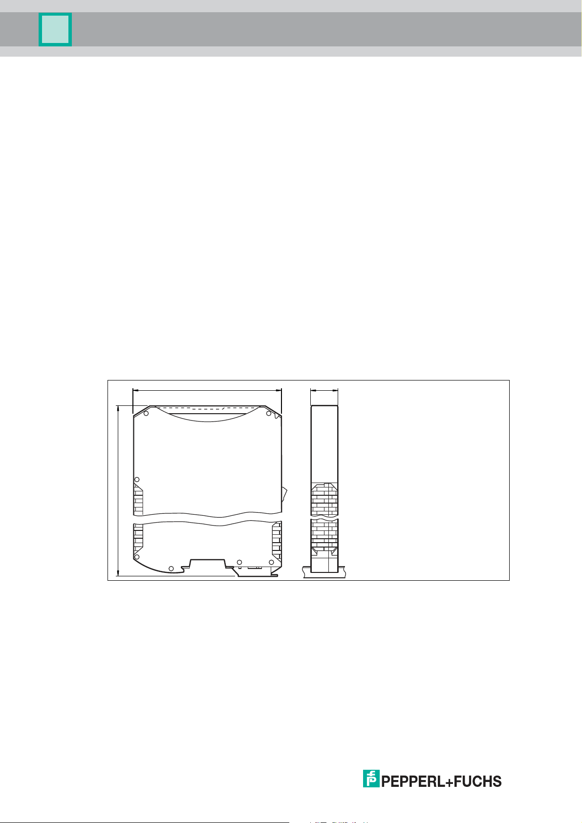
117
100
23
Product Description
2 Product Description
2.1 Use and Application
The WCS-PG 310 acts as an interface between the WCS reader and the PROFIBUS DP input
card of the control panel. The data is transferred between the WCS reader(s) and the WCSPG310 via the RS-485 interface, and from the WCS-PG310 to the control panel via the
PROFIBUS DP protocol.
You can connect up to four WCS readers of type LS221 or LS121. If you connect several
readers, they m ust have different addresses. The WCS-PG310 interface module constantly
queries the position values of the readers and always has the current reader data. The update
cycle for a reader is approximately 1 ms.
The WCS-PG310 interface module has the following configuration:
Baud rate: Max. 12 MBaud (automatic detection)
Diagnostic data: Max. 8 bytes
Sync: Supported
Freeze Supported
ID no.: 0x2079
2.2 Dimensions
The interface module housing has the following dimensions.
Figure 2.1 Dimen sions
2018-03
6
Page 7
WCS-PG310
3
4
7
1
5
2
6
Product Description
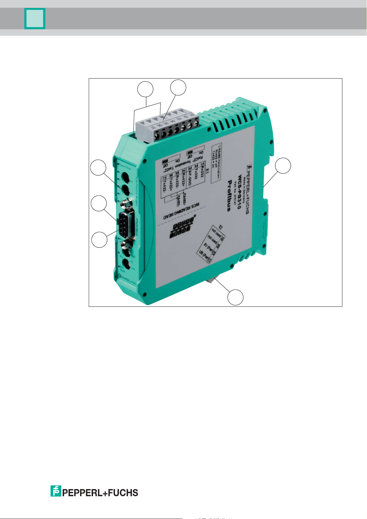
2.3 Design of the Device
Device components
Figure 2.2 Interface module overview
1 Slide switch for RS-485 terminator
2 X1: RS-485 interface
3 Mounting bracket
4 X2: Connection for power supply
5 PROFIBUS communication interface
6 Slide switch for PROFIBUS DP terminator
7 Front panel with rotary coding switches and indicator lights
2018-03
7
Page 8
WCS-PG310
PROFIBUS
Termination
Power/State
Bus
Power
1
2
4
8
S4
S5
State
Bus
State
Low
High
ID
Bus
o
n
o
f
f
WCS-PG310 Modul
A
B
C
D
0
1
2
3
4
5
6
7
8
9
A
B
C
D
0
1
2
3
4
5
6
7
8
9
A
B
C
D
0
1
2
3
4
5
6
7
8
9
A
B
C
D
0
1
2
3
4
5
6
7
8
9
Product Description
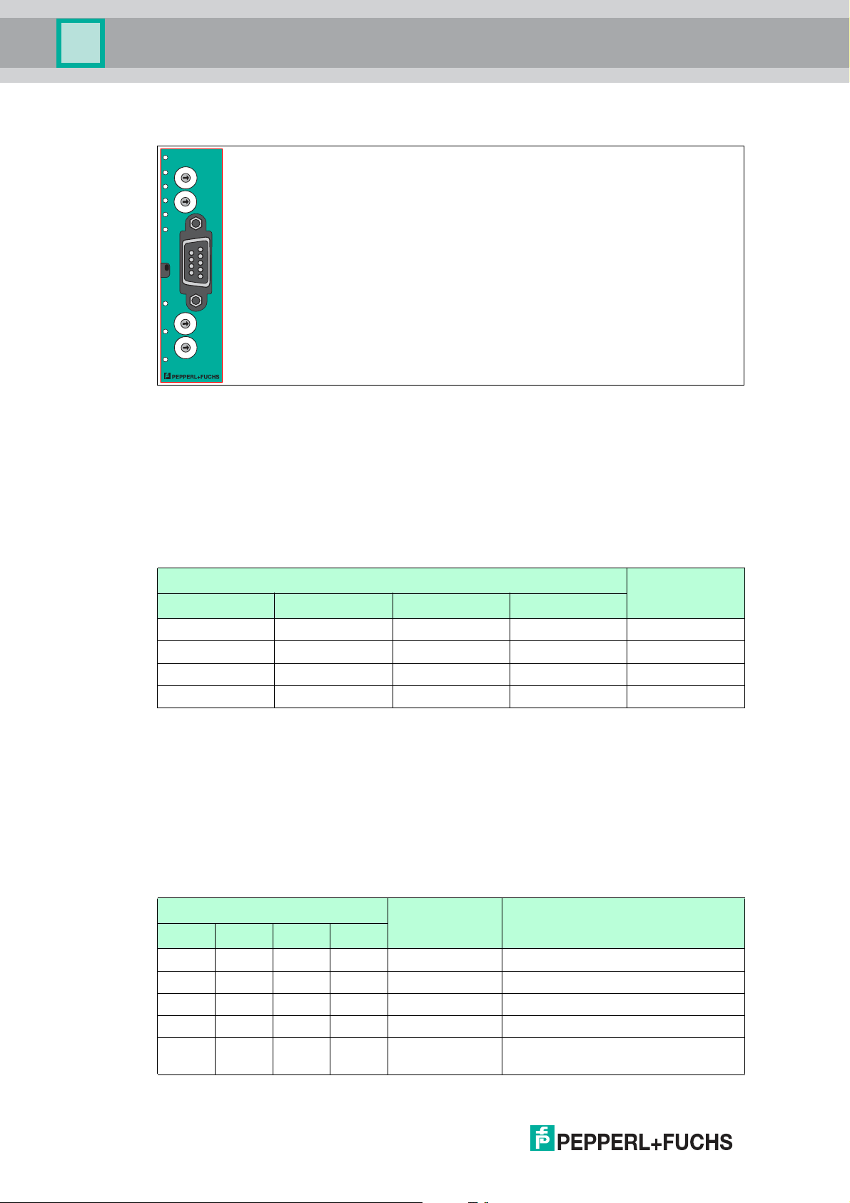
Front panel
Figure 2.3 Front panel overview
Power:
The "Power" LED is green: The WCS-PG310 interface module is correctly connected to the
power supply.
State:
The "State" LED is green: Data is being exchanged with the WCS readers. The four
"ErrorNo/Select ID" LEDs are used to display the number of the currently polled reader.
ErrorNo/Select ID Reader address
8 4 2 1
0 0 0 1 0
0 0 1 0 1
0 1 0 0 2
1 0 0 0 3
Table 2.1 Display via the four "ErrorNo/Select ID" LEDs when the "State" LED lights up green
The "State" LED is red: The interface module has detected an error or a warning. The interface
module uses the "ErrorNo/Select ID" LEDs to display the binary coded error number or warning
number, and sends the num ber to the PROFIBUS master via the external diagnostic byte.
Error (no. 1...5): Switch the interface module off and back on. If the error occurs
again, the module must be replaced.
Warning (no. 6...15): The warning provides information. The interface module displays
the warning for one m inute and then resets automatically.
ErrorNo/Select ID LED Error number Error description
LED8 LED4 LED2 LED1
0 0 0 0 0 Reserved
0 0 0 1 1 Hardware error
0 0 1 0 2 EEPROM error
0 0 1 1 3 Internal memory error
0 1 0 0 4 Fieldbus hardware error or incorrect
8
fieldbus ID
2018-03
Page 9

WCS-PG310
Product Description
ErrorNo/Select ID LED Error number Error description
LED8 LED4 LED2 LED1
0 1 0 1 5 Script error
0 1 1 0 6 Reserved
0 1 1 1 7 WCS reader communication, RS
1 0 0 0 8 WCS reader communication, RS
1 0 0 1 9 WCS reader communication, RS
1 0 1 0 10 General fieldbus error
1 0 1 1 11 Parity error or frame check error
1 1 0 0 12 Reserved
1 1 0 1 13 Fieldbus configuration error
1 1 1 0 14 Fieldbus data buffer overflow
1 1 1 1 15 Reserved
Table 2.2 Meaning of the error codes (display via the four "Error No/S elect ID" LEDs when the "State"
send buffer overflow
receive buffer overflow
timeout
LED lights up red and thus indicates an error or a warning)
Rotary coding switches S4 and S5
The rotary switches S4 and S5 have no function. Ensure that the two switches are at position 0
to enable the data exchange mode.
Bus Power:
The "BusPower" LED is green: The LED is connected directly to the electrically isolated supply
voltage for the PROFIBUS side.
Bus:
The "Bus" LED is red: The interface module cannot exchange any data on the PROFIBUS.
Bus State:
“BusState" LED PROFIBUS DP interface state
Lights up green Data exchange on the PROFIBUS
Flashes red/green Interface module is waiting for PRO FIBUS parameter data
Lights up red Error on the PROFIBUS
Flashes green Interface module is waiting for configuration data
ID High and ID Low rotary coding switches
You can set the PROFIBUS address with the two ID High and ID Low rotary switches. The digits
selected via the two rotary switches together form the P ROFIBUS address in hexadecimal
format.
Example: To set the address 19 (= 13h), set the ID High rotary switch to position "1" and the ID
Low rotary switch to position "3."
2018-03
9
Page 10

WCS-PG310
2
1
Installation
3 Installation
3.1 Mounting
Mounting the modules
The module is fastened to a DIN mounting rail with a width of 35 mm using a snap-on fixing
method.
Figure 3.1 Mounting
1. Hook the module (1) into the DIN mounting rail (2) from above and press it down until it snaps
into place.
The module is mounted.
Note!
Heat dissipation
You may place other modules to the left and right of the module.
Above and below the modules, there must be at least 5 cm of free space for heat dissipation.
2. You must connect the DIN mounting rail to the sw itch cabinet's equipotential busbar. The
connection wire must have a cross section of at least 10 mm2.
Note!
Vertical installation
You can also install the DIN mounting rail vertically, so that the modules can be rotated by 90°
for mounting.
2018-03
10
Page 11

WCS-PG310
Reader
WCS-LS221
WCS-PG310
RS 485 -
RS 485 +
24 V (Pwr)
0 V (Pwr)
X2-1
X2-2
X1-4
X1-5
X1-6
X1-7
GND UB+
PE
PE
UB+
GND
RS 485 +
RS 485 -
B-LineB-Line
A-Line
Probus-DP
1
2
3
4
5
6
7
8
9
Installation
3.2 Electrical Connection
Danger!
Device damage due to incorrect installation
Faulty installation of cables and connection lines can endanger the function and the electrical
safety of the device.
■
Note the permissible core cross section of the conductor.
■
If you are using stranded conductors, crimp the stranded conductors with wire end
ferrules.
■
Make sure that the insulation on the conductors extends all the way to the term inal.
■
Observe the tightening torque for the screws on the terminal. The tightening torque is
0.5 Nm.
■
Using an inappropriate tool may damage the screw heads. Use a slot-head screwdriver of
size 3.5 x 0.5.
■
Connecting an alternating current can damage the device or cause the device to
malfunction. Connect the device to direct current (DC).
Figure 3.2 Electrical connection
Plug X1 is located on the top side of the interface module, and plug X2 is located on the
underside.
Connection technology
You must/may use the following connection technology when wiring the assembly:
■
Standard screw/plug connection (supply + RS)
■
9-pin, D-SUB connector (PROFIBUS DP connection)
When using standard screw terminals, one line per connection point can be clamped. To
tighten the screws, use a screwdriver with a blade width of 3.5 mm.
Permissible cable cross section:
■
Flexible cable with wire end ferrule: 1 x 0.25 ... 1.5 mm
■
Solid cable: 1 x 0.25 ... 1.5 mm
2
The plug-in terminal strip combines a standard screw connection and a plug connector. The
plug connector is coded and can therefore not be plugged in incorrectly.
The 9-pin D-SUB connector is secured with two screws with a "4-40 UNC" thread. To tighten
the screws, use a screwdriver with a blade width of 3.5 mm. Observe the maximum tightening
torque of 0.4 Nm.
2018-03
2
11
Page 12

WCS-PG310
Installation
Connecting the power supply
Connect the operating voltage (10 VDC...30 VDC ) to terminals 1 and 2 of the 4-pin plug X2 on
the interface module. In addition, note the label on the module.
The "Power" LED lights up green.
Terminal Description
1 UB (Pwr) Operating voltage for interface m odule/
2 0 V (Pwr) Ground for interface module/ground for
3 Not used Not used
4 Not used Not used
Table 3.1 Terminal X2
Equipotential bonding connection
The connection to equipotential bonding occurs automatically when attaching to the DIN
mounting rail.
operating voltage for WCS reader
WCS reader
PROFIBUS DP communication interface
This interface can be found on the front of the housing in the form of a 9-pin D-SUB socket.
1. Connect the PROFIBUS connector to the D-SUB socket labeled "PROFIBUS."
2. Tighten the lock screws on the connector using a screwdriver.
3. If the assembly is at the beginning or at the end of the PROFIBUS cable, you must connect
the term inator that is integrated in the interface module. To do this, slide the slide switch to
the "on" position or to the upper end position.
4. If the assembly is not at the beginning or at the end, you must slide the slide switch to the
"off" position or to the lower end position.
Preparing for operation on the RS-485 interface
For operation on an RS-485 interface, the terminals on connector X1 must be connected as
follows:
1. Connect terminal 4 "Rx 422+" to terminal 6 "Tx 422+."
2. Connect terminal 5 "Rx 422-" to terminal 7 "Tx 422-."
Terminal Description
4 Rx 422+ RS-485+ data line to WCS reader
5 Rx 422- RS-485- data line to WCS reader
6 Tx 422+ Connect terminal 6 "Tx 422+" to terminal 4 "Rx 422+"
7 Tx 422- Connect terminal 7 "Tx 422-" to terminal 5 "Rx 422-"
Table 3.2 Terminal X1
12
2018-03
Page 13

WCS-PG310
*) RS485-Termination:
Rx422 = o
Tx422 = on
1
2
3
4
5
6
7
Rx232
Tx232
AP-GND
Rx422+
Rx422-
Tx422+
Tx422-
RS485+
RS485-
Rx422* Termination Tx422*
On O On O
X1
PROFIBUS
Termination
Power/State
Bus
Power
1
2
4
8
S4
S5
State
Bus
State
Low
High
ID
Bus
o
n
o
f
f
WCS-PG310 Modul
A
B
C
D
0
1
2
3
4
5
6
7
8
9
A
B
C
D
0
1
2
3
4
5
6
7
8
9
A
B
C
D
0
1
2
3
4
5
6
7
8
9
A
B
C
D
0
1
2
3
4
5
6
7
8
9
Termination
o
n
o
f
f
Installation
Note!
RS-485 bus termination
2018-03
If the interface module is operated as the first or last physical device in an RS-485 bus, there
must be a bus term ination on this module. To do this, set the "Rx 422 Termination" slide switch
to "Off" and the "Tx 422 Termination" slide switch to "On." This activates the RS-485 terminator
(150 Ω) built into the interface module.
If you only connect one WCS reader to the interface module, you must always activate the RS485 terminator; see also Cable routing in the RS-485 bus.
Note!
PROFIBUS termination
If the interface module is located at the beginning or end of the data cable to the control panel,
there must be a bus termination at this interface module. To do this, set the "Termination"
(PROFIBUS) slide switch to "On." This activates the PROFIBUS terminator built into the
interface module.
More information about bus termination can be found in the general fieldbus literature.
13
Page 14

WCS-PG310
4
3
2
1
Installation
3.3 Dismounting
Dismounting the modules
Use a suitable slot-head screwdriver for dismounting the module.
1. Disconnect all the supply and signal lines.
Figure 3.3 Dismoun ting
2. Insert the screwdriver (2) into the groove of the mounting bracket (3).
3. Press the screwdriver (2) in the specified direction until the lock on the DIN mounting rail (4)
opens, see figure.
4. Then press the module (1) upwards and lift it out of the DIN mounting rail.
2018-03
14
Page 15

WCS-PG310
Commissioning
4 Commissioning
4.1 Introduction
Warning!
Danger to life due to defective work
Errors during installation and commissioning can cause life-threatening injuries and significant
property damage.
■
Installation and commissioning m ust only be carried out by trained personnel in
accordance with the safety regulations.
Components
To comm ission the module, you will require the following components:
■
WCS-PG310 interface module
■
Connection cable from the interface module to the reader
■
Connector for the PROFIBUS connection to the interface m odule
■
PROFIBUS cable (this cable is usually already installed on site)
■
10 VDC...33 VDC power supply
■
GSD file (the GSD file can be obtained free of charge from our website w ww.pepperlfuchs.com)
Connecting the interface module
To ensure that the assembly functions correctly, you must carry out the following steps during
commissioning:
1. Set the PROFIBUS address on the front side of the module, using the two rotary switches
labeled "PROFIBUS ID High" and "PROFIBUS ID Low."
Note!
The PROFIBUS address that is set must match the configured address. It is only read in when
the module is switched on.
2. Connect the module to PROFIBUS using the interface labeled "PROFIBUS."
3. Connect the process device (reader). For information on commissioning the process device
(reader), please refer to its manual.
4. Ground the DIN mounting rail onto which the assembly is snapped.
5. Connect the direct current to the terminals provided.
6. Use any programming tool for configuration. The GSD file can be downloaded from our
website: ww w.pepperl-fuchs.com. Simply enter the product name or item number in the
Product/Keyword field and click the "Search" icon.
Note!
A more detailed description of the individual steps is provided on the following pages.
2018-03
15
Page 16

WCS-PG310
Commissioning
4.2 Connecting the WCS Reader
If you connect several WCS readers to one interface module, the WCS readers must have
different addresses. This will allow the programmable logic controller to allocate the data to the
correct WCS readers. If you only connect one WCS reader to an interface module, this WCS
reader always receives the address 0. You can connect up to four WCS readers to an interface
module via an RS-485 cable. Each WCS reader is supplied with the default address of 0.
Details of how to change the address of the WCS reader can be found in the configuration
instructions for the WCS reader.
The number of connected readers and their operating mode is configured in the hardware
project settings. Use the GSD file for the hardware project settings. This file can be
downloaded from our website: http://www.pepperl-fuchs.com.
Connection pin on reader Terminal on
WCS2A WCS2B WCS3A WCS3B
2 2 1 1 X2-1
4 4 2 2 X1-4
1 1 3 4 X1-5
3 3 5 3 X2-2
Table 4.1 Connecting the WCS reader(s)
interface module
4.3 Connecting the WCS-PG310 to the Network
A 9-pin connector is used to connect to the PROFIBUS DP, in accordance with the PROFIBUS
standard. You therefore need a 9-pin D-sub connector that you can plug into the 9-pin D-sub
socket on the device. This plug is not supplied with the interface module.
Pin Designation
1 Protective earth
2 Not used
3 B line
4 Control signal/repeater
5 Ground
6 5 V
7 Not used
8 A line
9 Ground
Table 4.2 Pin assignment for the 9-pin connector
1. Connect the PROFIBUS connector to the D-SUB socket labeled "PROFIBUS."
2. Tighten the lock screws on the connector using a screwdriver.
3. If the assembly is at the beginning or at the end of the PROFIBUS cable, you must connect
the term inator that is integrated in the gateway. To do this, slide the slide switch to the "on"
position.
4. If the assembly is not at the beginning or at the end, you must slide the slide switch to the
"off" position.
5. Set the PROFIBUS address on the fieldbus side of the assem bly, using the two rotary
switches labeled "PROFIBUS ID High" and "PROFIBUS ID Low." This setting uses
hexadecimal format.
DC
16
2018-03
Page 17

WCS-PG310
Commissioning
Example!
The PROFIBUS ID is 26 decimal = 1A hexadecimal. The "PROFIBUS ID High" switch must be
set to 1 and the "PROFIBUS ID Low" switch must be set to A.
6. If the rotary switch on the PROFIBUS side (PROFIBUS ID) is set to "7E" (= 126), the
gateway uses a PROFIBUS address that is stored in the EEPROM. This address is 126 by
default and can only be changed by a PROFIBUS master via PROFIBUS itself. The address
126 is reserved for this purpose in PROFIBUS, i.e., a slave with this address can never
exchange data, but can only be configured with a new ID.
7. If the rotary switch is set to a value between 0 and 125, the gateway uses this PROFIBUS ID
and it is not possible to change the setting via a master.
4.4 Integrating WCS-PG310 into the PROFIBUS System
Warning!
Risk of injury due to incorrect configuration
An error during the configuration of the device can override the fail-safe function, causing a
danger to people and machinery.
■
Ensure that the device is programmed exclusively by qualified personnel.
■
Only put devices into operation after they have been configured correctly.
You will need a GSD file to operate the module described in this manual. The GSD file must be
imported into the corresponding configuration tool before commissioning the module. The
GSD file can be downloaded from our website: www.pepperl-fuchs.com. Simply enter the
product name or item number in the Product/Keyword field and click the "Search" icon.
Select your product from the list of search results. Click on the information you require in the
product information list, e.g., Software.
A list of all available downloads is displayed.
Note!
Various configuration tools are available to allow you to configure the interface module. By way
of example, this manual describes the configuration of a Siem ens control panel with the WCSPG310 interface module using the TIA Portal V14. If you are using a programmable logic
controller (PLC) from a different manufacturer, the process will be similar to the one described
here.
2018-03
17
Page 18

WCS-PG310
1
1
2
3
Commissioning
Installing the GSD file
Figure 4.1 GSD file manage
1. In the menu bar, click the "Options" button and select the function "Install device description
file (GSD)."
The "Install device description file" window opens.
18
Figure 4.2 Search GSD file
2. Click the button with the three dots (1), which allows you to search for your GSD file on the
storage medium.
3. Select the folder containing the GSD file (2) and click "OK" (3) to confirm your selection.
2018-03
Page 19

WCS-PG310
1
2
Commissioning
Figu re 4.3 Install GSD file
4. Select the GSD file to install by checking the box (1) to the left of the filename.
5. Click the "Install" button (2). The installation process m ay take a few minutes.
Once the file is installed successfully, the system issues a notification that the installation
was successful. Close this window. The device data is added to the hardware catalog.
2018-03
19
Page 20

WCS-PG310
1
Commissioning
Integrating a module into the project
20
Figure 4.4 Hardware catalogue
1. Open the hardware catalog and browse through the tree structure until you see the icon labeled "276147" (1) (Other field devices > PROFIBUS DP > Gateways > PEPPERL+FUCHS
> Pepperl+Fuchs > WCS > WCS-PG310 > Header module > 276147).
2018-03
Page 21

WCS-PG310
2
1
Commissioning
Figu re 4.5 Integrating gsd file
2. Select module "276147" (1) from the hardware catalog and drag this module into the
network view (2).
The selected module is displayed in the network view window (2).
3. Connect the module to the control panel. To do this, move the mouse onto the PROFIBUS
interface that is highlighted in purple on the control panel, click the left mouse button, and
drag the line show n to the PROFIBUS interface on the module. O nce there, release the left
mouse button again.
A PROFIBUS subsystem is created.
Setting the number of readers, operating mode, and addresses
You have the option to connect up to four readers to the interface module. To do this, you must
specify the number of modules and their properties in the control panel. Several selection
options are available in the hardware catalog.
Note!
Do not use the "universal module" when configuring the device.
2018-03
21
Page 22

WCS-PG310
2
1
3
Commissioning
Figure 4.6 Device view
1. Switch to the "Device view" tab (1) in the "Devices & Networks" window.
2. Double-click to select the module with the appropriate number of readers and operating
mode from the hardware catalog (2).
Note!
Depending on your application, select one, two, three, or four connected WCS readers and the
operating mode. When in the "only Position" operating mode, the WCS readers output their
position. In the "Position and Speed" operating mode, the WCS readers output their position
and the speed at which they are currently moving.
Regardless of the number of WCS readers, 1 byte is reserved for querying the diagnostics for
the WCS readers in the master. For the response data, 4 bytes are reserved for each WCS
reader in the "only Position" operating mode (configuration data for four WCS readers: 0x20,
0xD1, 0xD1, 0xD1, 0xD1). In the "Position and Speed" operating mode, 6 bytes are reserved
for each WCS reader (configuration data for four WCS readers: 0x20, 0xD2, 0xD2, 0xD2,
0xD2).
The selected module is added to the device view (3).
22
2018-03
Page 23

WCS-PG310
1
2
3
Commissioning
Figu re 4.7 Network view
3. Switch to the "Network View" tab (1) in the "Devices & Networks" window.
4. To change the input and output address for the module, double-click on the module (2) in
the hardware catalog.
5. Selecting the Properties > General tab displays the control panel properties (3) in the
inspector window below the network view.
6. If necessary, enter the new address of the module in the input field under PROFIBUS
address > Parameters > Address.
Note!
You must assign unique addresses for data communication between the module and the
reader. If you connect several readers to one module, the readers must have different
addresses. This will allow the control panel to allocate the data to the correct module and
readers. If you only connect one reader to a module, this reader always receives the address 0.
You can connect up to four readers to a module via an RS-485 cable. Each reader is supplied
with the default address of 0. Details of how to change the address of the reader can be found
in the configuration instructions for the reader.
4.5 Data Format for Modules
In "only Position" operating mode, 4 bytes are reserved for each WCS reader.
Bit 7 6 5 4 3 2 1 0
Byte 0 0 0 0 0 0 P18 P17 P16
Byte 1 P15 P14 P13 P12 P11 P10 P09 P 08
Byte 2 P07 P06 P05 P04 P03 P02 P01 P 00
Byte 3 0 0 0 DB ERR OUT A1 A0
Table 4.3 Data format for each connected WCS reader in "only Position" ope rating mode, reader
address = 0... 3
In "Position and Speed" operating mode, 6 bytes are reserved for each WCS reader.
2018-03
23
Page 24

WCS-PG310
Commissioning
Bit 7 6 5 4 3 2 1 0
Byte 0 0 0 0 0 0 P18 P17 P16
Byte 1 P15 P14 P13 P12 P11 P10 P09 P08
Byte 2 P07 P06 P05 P04 P03 P02 P01 P00
Byte 3 0 0 0 DB ERR OUT A1 A0
Byte 4 0 0 0 0 0 0 0 0
Byte 5 0 S06 S05 S04 S03 S02 S01 S00
Table 4.4 Data format for each conn ected WCS reader in "Position and Speed" operating mode,
Pxx: position data, P00 = LSB
Sxx: speed (in multiples of 0.1 m/s), S00 = LSB
Example: Byte 5 = 00011011 = 27, corresponds to 2.7 m/s
A1, A0: reader address, 00 = WCS reader address #1
DB: pollution display, 1 = cleaning necessary
OUT: code rail loss, 0 = code rail recognized
ERR: error display, error code (LEDs)
reader addres s = 0...3
Address bits A1 and A0
A1 A0 Reader address
0 0 Reader address 0
0 1 Reader address 1
1 0 Reader address 2
1 1 Reader address 3
Status bits
DB ERR OUT Description
0 0 0 Current position value binary coded in
P00...P18
0 0 1 WCS reader outside of the code rail,
not a position value
P0...P18=0: WCS reader partly
outside the code rail
P0=1, P2...P18=0: WCS reader
completely outside of the code rail
1 0 0 Current position value binary coded in
P00...P18
1 0 1 No position value, WCS reader
outside of the code rail
X 1 X No position value, error message from
WCS reader, error num ber binary
coded in P00...P18
Optical state of WCS
reader
Good
Good
Poor
Poor
-
24
2018-03
Page 25

WCS-PG310
Reading head
Interface or control
(PLC)
Appendix
5 Appendix
5.1 Cable Routing in the RS-485 Bus
The data cables must always form an in-line connection between the first and the last node.
This in-line connection must end with a terminator.
The RS-485 terminators are integrated in the WCS readers and can be switched on and off
with the interface module.
If only one WCS reader is connected, one device is connected at the beginning and one
device is connected at the end of the data line.
2018-03
Figure 5.1 Connection of one reading head
If two WCS readers are connected to one inter face module, there are two wiring versions:
■
Version A:
One WCS reader is located at the beginning and one WCS reader at the end of the data
line. For both WC S readers, the RS-485 terminator is activated. The interface module is
located between these two readers and does not have an RS-485 terminator. Each WCS
reader is connected to the interface module by a separate data cable.
25
Page 26

WCS-PG310
Interface or control
(PLC)
Reading head
Reading head
Appendix
Figure 5.2 Connection o f two reading heads, Version A
■
Version B:
The interface module is located at the beginning of the data line; one WCS reader is
located at the end of the data line. Both need the RS-485 terminator. The second WCS
reader is connected to the line connection between the interface module and the first
WCS reader through a short spur (length <1 m). Use a bus term inal to connect the spur.
26
2018-03
Page 27

WCS-PG310
Reading head
Reading head
Interface or control
(PLC)
Spur line (max. 1 m)
Bus terminal
Appendix
Figure 5.3 Connection of two reading heads, Version B
The wiring version used depends on which is best suited for the application. If three or four
WCS readers are used on the same interface module, connect these using spurs as shown in
variant B.
2018-03
27
Page 28

WCS-PG310
Appendix
5.2 Data Cables and Accessories
RS-485 data cable
For the RS-485 data transfer path, a four-wire, shielded, twisted pair data cable must be used.
One wire pair is used for the supply voltage, and one pair for the RS-485 data connection. The
maximum length of the cable depends on the data transfer capacity of the data cable—corecore—and on the cross section of the cables for power supply of the WCS readers. For data
transfer, a small core cross section, and thus small cable capacitance is an advantage,
whereas for the power supply the largest possible cross section is required. The table below
shows the possible cable lengths depending on the cable cross section.
In the calculations, the worst-case scenario was assum ed: All WCS readers are located at the
end of the data line. In the case of large cable lengths, and when connecting multiple WCS2
readers with heating, six-wire data cable (3 x 2) can be used. These data cables use two pairs
for the power supply (doubling the cable cross section), and one pair for the RS-485 data line.
Capacitance (corecore)
60 pF 500 m 500 m 300 m
90 pF 500 m 450 m 275 m
120 pF 500 m 400 m 250 m
The table shows the possible cable lengths depending on the cable capacitance (core-core).
The number of connected WCS readers is of no significance.
RS-485 interface
19.2 KB (LS246) 62.5 KB (LS221) 187.5 KB (LS211)
WCS-DCS / WCS-DCF data cables
There are 2 types of data cable available:
. WCS-DCS for stationary cable routing
. WCS-DCF for trailing cable and drag chain installations.
The data cables are twisted pairs and have a tinned copper braided shield. The braided shield
surrounds all wire pairs. The parameters of the data cable for RS-485 and SSI data transfer
applications are listed in the table below.
WCS-DCS WCS-DCF
Capacitance (core-core) 95 pF/m 60 pF/m
Cross section
Number of wires 6 (3 x 2) 6 (3 x 2)
External diameter 5.8 mm 7.5 m m
Temperature range -30 °C ... 70 °C -40 °C ... 70 °C
Order designation WCS-DCS WCS-DCF
0.14 mm
2
0.25 mm
2
28
2018-03
Page 29

WCS-PG310
Appendix
Single-ended female cordsets and adapter cables
Field-attachable female connectors M12 x 1
straight 4 6 mm – 8 mm V1-G-PG9
angled 4 6 mm – 8 mm V1-W-PG9
straight 5 6 mm – 8 mm V15-G-PG9
angled 5 6 mm – 8 mm V15-W-PG9
straight 6 6 mm – 8 mm V17-G-PG9
angled 6 6 mm – 8 mm V17-W-PG9 *)
Table 5.1 *) Cable outle t on top, not variable
Shielded connection cable with molded single-ended female cordset
straight 4 2 m V1-G-2M-PUR-ABG
straight 4 5 m V1-G-5M-PUR-ABG
angled 4 2 m V1-W-2M-PUR-ABG
angled 4 5 m V1-W-5M-PUR-ABG
straight 5 5 m V15-G-5M-PU R-ABG
angled 5 5 m V15-W-5M-PUR-ABG
straight 8 2 m V19-G-2M-PU R-ABG
straight 8 5 m V19-G-5M-PU R-ABG
Number of poles Cable diameter Order designation
Number of poles Cable length Order designation
2018-03
29
Page 30

FACTORY AUTOMATION –
SENSING YOUR NEEDS
Worldwide Headquarters
Pepperl+Fuchs GmbH
68307 Mannheim · Germany
Tel. +49 621 776-0
E-mail: info@de.pepperl-fuchs.com
USA Headquarters
Pepperl+Fuchs Inc.
Twinsburg, Ohio 44087 · USA
Tel. +1 330 4253555
E-mail: sales@us.pepperl-fuchs.com
Asia Pacific Headquarters
Pepperl+Fuchs Pte Ltd.
Company Registration No. 199003130E
Singapore 139942
Tel. +65 67799091
E-mail: sales@sg.pepperl-fuchs.com
www.pepperl-fuchs.com
Subject to modifications
Copyright PEPPERL+FUCHS • Printed in Germany
/ TDOCT5979__ENG
03/2018
 Loading...