

Page 1

WCS-EIG310
WCS Interface Module
EtherNet/IP
Manual
Page 2

With regard to the supply of produ cts, the current issue of the following document is applicable: The
General Terms of Delivery for Products and Ser vices of the Electrical Industry, published by the Central
Association of the Electrical Industry (Zentralverband Elektrotechnik und Elektroindustrie (ZVEI) e.V.)
in its most recent version as well as the supplementary clause: "Expanded reservation of proprietorship"
Worldwide
Pepperl+Fuchs Group
Lilienthalstr. 200
68307 Mannheim
Germany
Phone: +49 621 776 - 0
E-mail: info@de.pepperl-fuchs.com
North American Headquarters
Pepperl+Fuchs Inc.
1600 Enterprise Parkway
Twinsburg, Ohio 44087
USA
Phone: +1 330 425-3555
E-mail: sales@us.pepperl-fuchs.com
Asia Headquarters
Pepperl+Fuchs Pte. Ltd.
P+F Building
18 Ayer Rajah Crescent
Singapore 139942
Phone: +65 6779-9091
E-mail: sales@sg.pepperl-fuchs.com
https://www.pepperl-fuchs.com
Page 3

WCS-EIG310
Contents
1 Introduction................................................................................................................ 4
1.1 Content of this Document ............................................................................. 4
1.2 Target Group, Personnel ............................................................................... 4
1.3 Symbols Used ................................................................................................ 4
2 Product description................................................................................................... 6
2.1 Use and Application ...................................................................................... 6
2.2 Dimensions.....................................................................................................6
2.3 Design of the Device...................................................................................... 7
3 Installation................................................................................................................ 11
3.1 Mounting....................................................................................................... 11
3.2 Electrical Connection .................................................................................. 12
3.3 Dismounting ................................................................................................. 14
4 Commissioning........................................................................................................ 15
4.1 Introduction.................................................................................................. 15
4.2 Connecting the WCS Read Head................................................................15
4.3 Connection to the Network ......................................................................... 17
4.4 Setting the IP Address and Subnet Screen............................................... 18
4.5 Network Settings ......................................................................................... 19
5 Communication with WCS read heads .................................................................. 21
5.1 Request Byte for Read Heads .................................................................... 21
5.2 Data Format for Modules ............................................................................ 21
6 Appendix .................................................................................................................. 23
6.1 Software Tool for RSLogix 5000, V15, and V17 ......................................... 23
6.2 Cable Routing in the RS-485 Bus ...............................................................23
6.3 Data Cable ....................................................................................................26
2020-03
3
Page 4

WCS-EIG310
Introduction
1 Introduction
1.1 Content of this Document
This document contains information required to use the product in the relevant phases of the
product life cycle. This may include information on the following:
• Product identification
• Delivery, transport, and storage
• Mounting and installation
• Commissioning and operation
• Maintenance and repair
• Troubleshooting
• Dism ounting
• Disposal
Note
For full information on the product, refer to the further documentation on the Internet at
www.pepperl-fuchs.com.
The docum entation comprises the following parts:
• This document
• Datasheet
In addition, the documentation may comprise the following parts, if applicable:
• EU-type examination certificate
• EU declaration of conformity
• Attestation of conformity
• Certificates
• Control drawings
• Instruction manual
• Other documents
1.2 Target Group, Personnel
Responsibility for planning, assembly, commissioning, operation, maintenance, and dismounting lies with the plant operator.
Only appropriately trained and qualified personnel may carry out mounting, installation, commissioning, operation, maintenance, and dismounting of the product. The personnel must have
read and understood the instruction manual and the further documentation.
Prior to using the product make yourself familiar with it. Read the document carefully.
2020-03
4
Page 5
WCS-EIG310
Introduction
1.3 Symbols Used
This document contains symbols for the identification of warning messages and of informative
messages.
Warning Messages
You will find warning messages, whenever dangers may arise from your actions. It is mandatory
that you observe these warning messages for your personal safety and in order to avoid property damage.
Depending on the risk level, the warning messages are displayed in descending order as follows:
Danger!
This symbol indicates an imminent danger.
Non-observance will result in personal injury or death.
Warning!
This symbol indicates a possible fault or danger.
Non-observance may cause personal injury or serious property damage.
Caution!
This symbol indicates a possible fault.
Non-observance could interrupt the device and any connected systems and plants, or result in
their complete failure.
Informative Symbols
Note
This symbol brings important information to your attention.
Action
This symbol indicates a paragraph with instructions. You are prompted to perform an action or
a sequence of actions.
2020-03
5
Page 6
WCS-EIG310
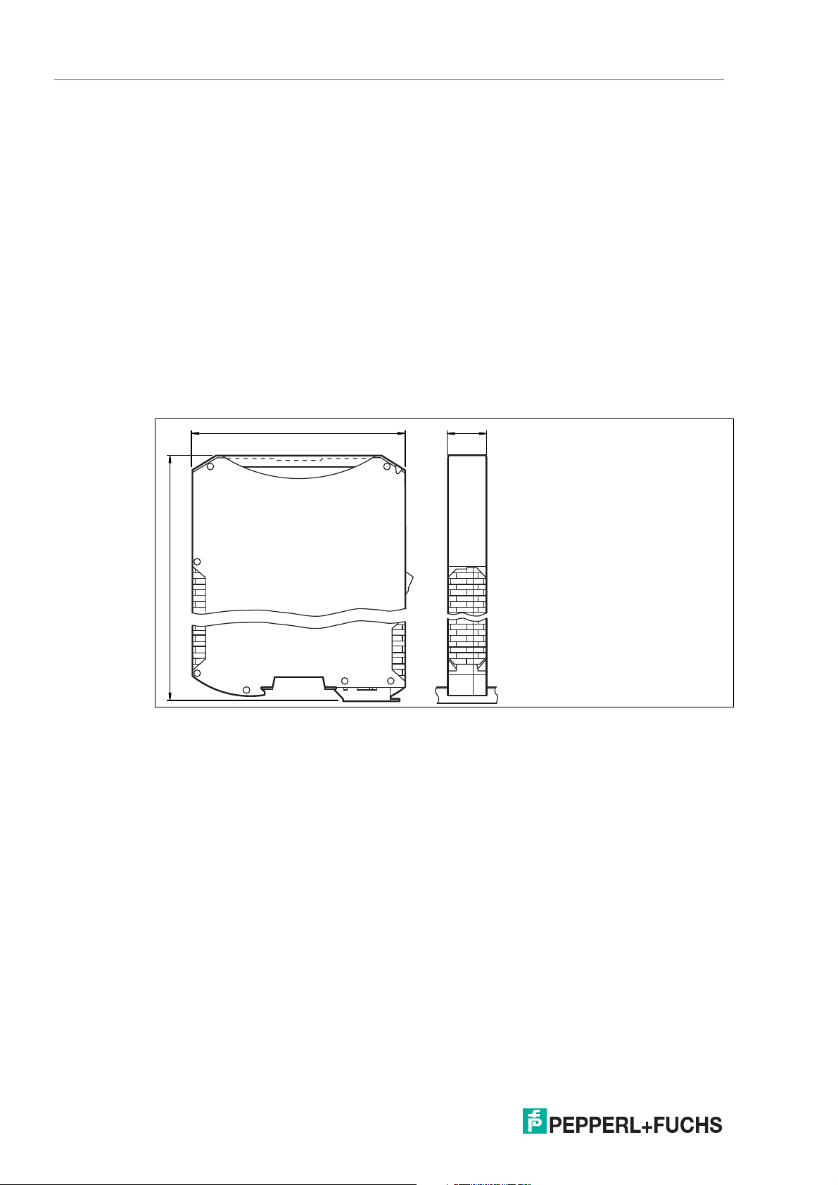
115
100
23
Product Description
2 Product Description
2.1 Use and Application
The WCS-EIG310 interface module acts as an interface between the WCS read head and the
EtherNet/IP controller. Data is transferred between the WCS read head and the interface module via an RS-485 interface. The data from the interface module to the control panel is transferred via the EtherNet/IP protocol.
You can connect a maximum of four WCS read heads of type LS221 (and/or LS121) to one
WCS-EIG310 interface module. If you connect several WCS read heads, they must have different addresses. The number of connected WCS read heads is configured in the hardware project settings.
2.2 Dimensions
The interface module housing has the following dimensions.
Figure 2.1 Dime nsions
2020-03
6
Page 7
WCS-EIG310
4
3
1
6
2
5
Product Description
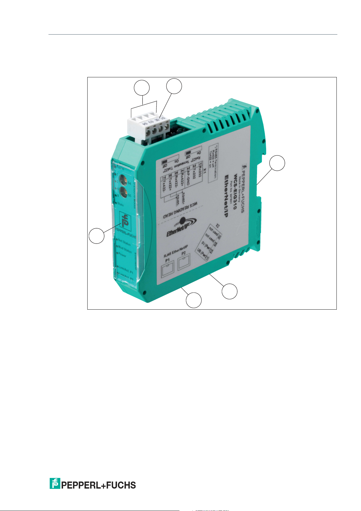
2.3 Design of the Device
Device Components
Figure 2.2 Interface mo dule overview
1 RS-485 bus termination slide switch
2 X1: RS-485 interface
3 Mounting bracket
4 X2: Connection for power supply
5 X3: EtherNet/IP communication interface
6 Front panel with rotary coding switch and LED indicator lights
2020-03
7
Page 8
WCS-EIG310
Power
1
2
4
8
S4
S5
State
WCS-EIG310 Modul
A
B
C
D
0
1
2
3
4
5
6
7
8
9
A
B
C
D
0
1
2
3
4
5
6
7
8
9
Net Status
Power
Link/Act. P1
Link/Act. P2
Ethernet/IP
Mod Status
Product Description
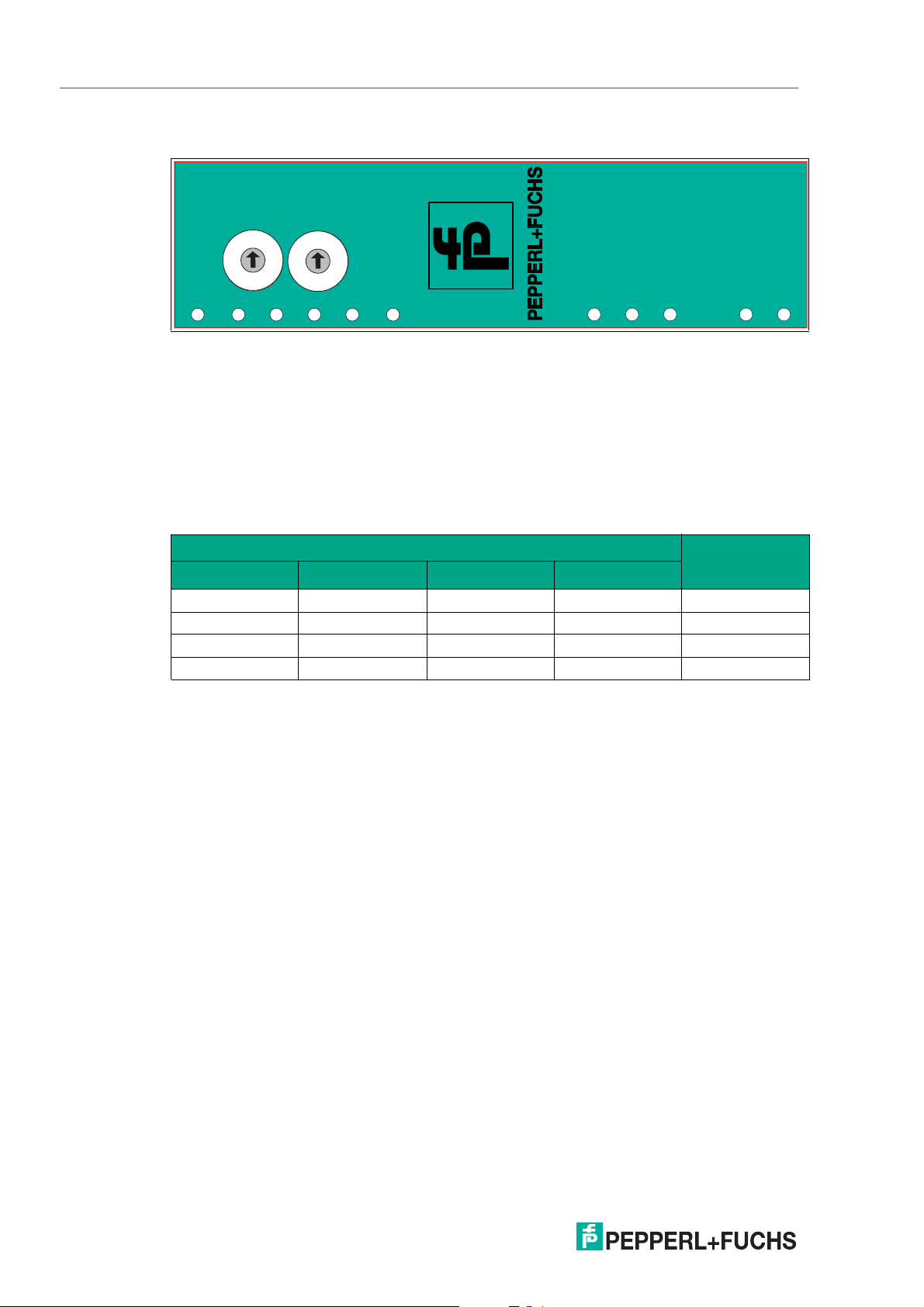
Front Panel
Figure 2.3 Front panel overview
WCS read head: LED status indicator and rotary coding switch
Power:
The "Power" LED lights up green: power supply is present.
State:
The "State" LED is green: Data is being exchanged with the WCS read heads. The four "Error
No/Select ID" LEDs are used to display the number of the currently polled WCS read head.
Error No/Select ID Read head
8 4 2 1
0 0 0 1 0
0 0 1 0 1
0 1 0 0 2
1 0 0 0 3
Table 2. 1 Display via the four "ErrorNo/Select ID" LEDs whe n the "State" LED lights up green
address
The "State" LED lights up red: The interface module has detected an error or a warning. The
inter face module displays the binary coded error and/or warning number via the "Error
No/Select ID" LEDs.
Error (No. 1...5): Switch the interface module off and back on. If the error occurs
again, the module must be replaced.
Warning (No. 6...15): The warning provides information. The interface module displays
the warning for one minute and then resets automatically.
8
2020-03
Page 9

WCS-EIG310
Product Description
LED ErrorNo/Select ID Error number Error description
LED8 LED4 LED2 LED1
Table 2.2 Significance of the error codes (display via the four "Error No/Select ID" LE Ds when the
0 0 0 0 0
0 0 0 1 1
0 0 1 0 2
0 0 1 1 3
0 1 0 0 4
0 1 0 1 5
0 1 1 0 6
0 1 1 1 7
1 0 0 0 8
1 0 0 1 9
1 0 1 0 10
1 0 1 1 11
1 1 0 0 12
1 1 0 1 13
1 1 1 0 14
1 1 1 1 15
"State" LED lights up red and thus indicates an error or a warn ing)
Reserved
Hardware error
EEPROM error
Internal memory error
Fieldbus hardware error or incorrect
fieldbus ID
Script error
Reserved
WCS read head communication, RS
send buffer overflow
WCS read head communication, RS
receive buffer overflow
WCS read head communication, RS
timeout
General fieldbus error
Parity error or frame check error
Reserved
Fieldbus configuration error
Fieldbus data buffer overflow
Reserved
Rotary coding switches S4 and S5
The rotary coding switch S4 is used to determ ine the number of read heads. The rotary coding
switch S5 has no function and is always in the "0" switch position.
2020-03
9
Page 10

WCS-EIG310
Product Description
EtherNet/IP: LED status indicator
Net Status:
Table 2. 3 "Net Status" LED display
Mod Status:
Table 2. 4 "Mod Status" LED disp lay
"Net Status" LED Interface state
Flashes green/red Self-test
Lights up green Connection present, data exchange is active
Flashes green Waiting for a connection to be established
Flashes red Connection has timed out
Lights up red IP address assigned twice
"Mod Status" LED Interface state
Flashes green/red Self-test
Lights up green Data exchange active
Flashes green Standby/module waiting for connection
Flashes red Module error
Lights up red Serious module error
Power:
The "Power" LED lights up green: This LED is directly connected to the supply voltage of the
serial interface (RS232/422/485).
Link/Activity P1:
The "Link/Activity Port 1" LED is directly activated by the Ethernet controller and lights up green
when the interface module at port 1 is on a working network. When there is data traffic on the
network, the LED flashes green at the same speed as the sent/received data.
Link/Activity P2:
The "Link/Activity Port 2" LED is directly activated by the Ethernet controller and lights up green
when the interface module at port 2 is on a working network. When there is data traffic on the
network, the LED flashes green at the same speed as the sent/received data.
10
2020-03
Page 11
WCS-EIG310
2
1
Installation
3 Installation
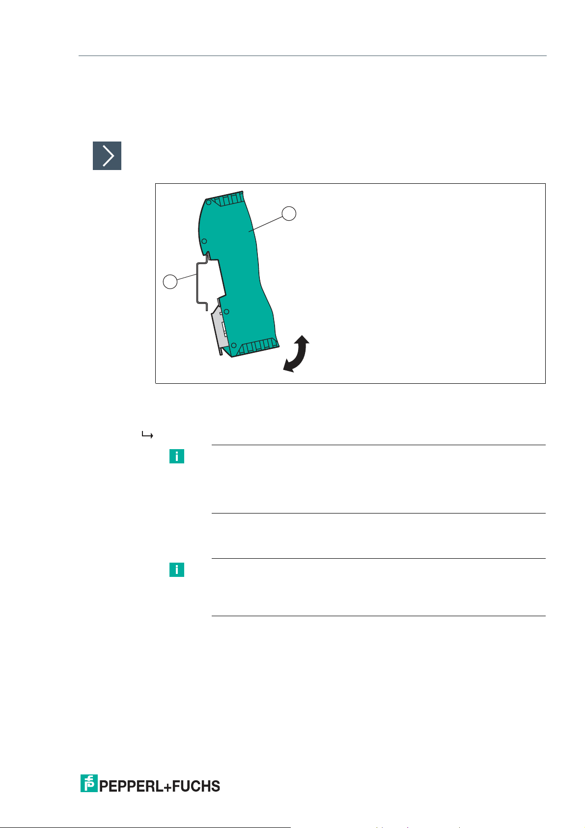
3.1 Mounting
Mounting the Modules
The module is fastened to a DIN mounting rail with a w idth of 35 mm using a snap-on fixing
method.
Figure 3.1 Mounting
1.
Hook the module (1) onto the DIN mounting rail (2) from above and press it down until it snaps
into place.
The module is mounted.
Note
Heat Dissipation
You may place other modules to the left and right of the module.
Above and below the modules, there must be at least 5 cm of free space for
heat dissipation.
2.
You must connect the DIN mounting rail to the switch cabinet's equipotential busbar. The
connection wire must have a cross section of at least 10 mm2.
Note
Vertical Installation
You can also install the DIN mounting rail vertically, so that the modules can be
rotated by 90° for mounting.
2020-03
11
Page 12

WCS-EIG310
Reading head
Ethernet /IP
Interface
WCS.-LS221
WCS-EIG310
RS 485 -
RS 485 +
24 V (Pwr)
0 V (Pwr)
X2-1
X2-2
X1-4
X1-5
X1-6
X1-7
SUB
GND
SDA
SDB
GND UB+
PE
PE
Ethernet /IP
Port 2
Ethernet
RJ45
Port 1
Ethernet
RJ45
UB+
GND
RS 485+
RS 485-
Installation
3.2 Electrical Connection
Danger!
Device damage due to incorrect installation
Incorrect installation of cables and connection lines can endanger the function and the electrical safety of the device.
• Observe the permissible core cross section of the conductor.
• If you are using stranded conductors, crimp the stranded conductors with wire end fer-
rules.
• Make sure that conductors are insulated all the way up to the terminal.
• Observe the tightening torque for the screws on the terminal. The tightening torque is
0.5 N m.
• Using an unsuitable tool may damage the screw heads. Use a slot-head screwdriver sized
3.5 x 0.5.
• Connecting an alternating current can damage the device or cause the device to malfunc-
tion. Connect the device to direct current (DC).
12
Figure 3.2 Elect rical connection
Plug X1 is located on the top side of the interface module, and Plug X2 is located on the underside.
Connection Technology
You must/may use the following connection technologies when wiring the assembly:
• Standard screw/plug connection (supply + RS)
• 8-pin RJ45 connection (EtherNet/IP connection)
When using standard screw terminals, one cable per connection point can be clamped. To
tighten the screws, use a screwdriver with a blade width of 3.5 m m.
Permissible cable cross section:
• Flexible cable with wire end ferrule: 1 x 0.25 ... 1.5 mm
• Solid cable: 1 x 0.25 ... 1.5 mm
2
The plug-in terminal strip combines a standard screw connection and a plug connector. The
plug connector is coded and therefore cannot be plugged in incorrectly.
2
2020-03
Page 13

WCS-EIG310
Installation
Connecting the Power Supply
Connect the operating voltage (10 VDC ... 30 VDC) to terminals 1 and 2 of the 4-pin plug X2 on
the interface module. In addition, note the label on the module.
The "Power" LED lights up green.
Terminal Description
1
2
3
4
Table 3.1 Terminal X2
UB+ (Pwr) Operating voltage of interface mod-
ule/
operating voltage of sensor
0 V (P wr) Ground of interface module/ground of
sensor
not used is not used
not used is not used
Equipotential Bonding Connection
The connection to equipotential bonding occurs automatically w hen attaching to the DIN
mounting rail.
EtherNet/IP Communication Interface
This interface can be found on the interface module in the form of two 8-pin RJ45 sockets on
the bottom of the housing.
Insert the EtherNet/IP connector into one of the RJ45 socket(s) with the inscription "In" (cable
from m aster) or "Out" (further cable to the next EtherNet/IP slave).
Note
Ensure that the cable length to the neighboring EtherNet/IP participants is at
least 0.6 m.
2020-03
13
Page 14

WCS-EIG310
*) RS485 Termination:
Rx422 = off
Tx422 = on
1
2
3
4
5
6
7
Rx232
Tx232
AP-GND
Rx422+
Rx422-
Tx422+
Tx422-
RS485+
RS485-
Rx422* Termination Tx422*
On Off On Off
X1
Installation
Preparing for Operation on RS-485 Interface
For operation on an RS-485 interface, the terminals on connector X1 must be connected:
Connect the read head to the terminal. Use the enclosed jumper to connect the terminals to
each other
Figure 3.3 Terminal X1
14
2020-03
Page 15
WCS-EIG310
4
3
2
1
Installation
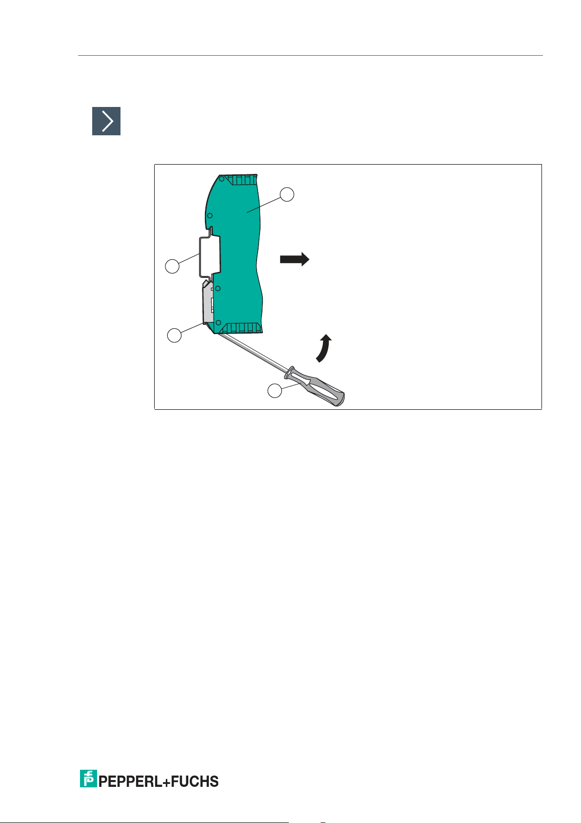
3.3 Dismounting
Dismounting the modules
Use a suitable slot-head screwdriver for dismounting the module.
1.
Disconnect all the supply and signal lines.
Figure 3.4 Dismounting
2.
Insert the screwdriver (2) into the groove of the mounting bracket (3).
3.
Press the screwdriver (2) in the specified direction until the lock on the DIN mounting rail (4)
opens, see figure.
4.
Then press the module (1) upwards and lift it out of the DIN mounting rail.
2020-03
15
Page 16

WCS-EIG310
Commissioning
4 Commissioning
4.1 Introduction
Warning!
Danger to life due to defective work
Errors during installation and commissioning can cause life-threatening injuries and significant
property damage.
• Installation and commissioning must only be carried out by trained personnel in accor-
dance with safety regulations.
Components
To commission the module, you will require the following components:
• WCS-EIG310 interface module
• EDS file (the EDS file can be obtained free of charge from our website www.pepperl-
fuchs.com).
• Cordset from the interface module to the sensor
• Connector for the EtherNet/IP connection to the interface m odule
• Ethernet cable
• 10 VDC ... 30 VDC voltage supply
Downloading the EDS File
You will need an EDS file to operate the module described in this manual. The EDS file must be
imported into the corresponding configuration tool before commissioning the module. The EDS
file can be downloaded from our website: www.pepperl-fuchs.com. Simply enter the product
name or item number in the product/keyword field and click the "Search" icon.
1.
To access the product detail page for the device, go to http://www.pepperl-fuchs.com and enter
information about the device (e.g., the product description or the item number) into the search
function.
2.
Select your product from the list of search results. Click on the information you require in the
product information list, e.g., Software.
A list of all available downloads is displayed.
2020-03
15
Page 17
WCS-EIG310
Commissioning
4.2 Connecting the WCS Read Head
If you connect several WCS read heads to one interface module, the WCS read heads must
have different addresses. This will allow the programmable logic controller to allocate the data
to the correct WCS read heads. If you only connect one WCS read head to an interface module, this WCS read head always receives the address 0. You can connect up to WCS read
heads to an interface module via an RS-485 cable. Each WCS read head is supplied with the
default address of 0. Details of how to change the address of the WCS read head can be found
in the configuration instructions for the WCS read head.
WCS read head connection pin Terminal on interface mod-
WCS2B WCS3B
2 1 X2-1
4 2 X1-4
1 4 X1-5
3 3 X2-2
Table 4. 1 Connection of WCS read heads
ule
Setting the Number of Connected WCS Read Heads
Set the number of connected WCS read heads with the rotary switch S4 in accordance with the
table "Rotary switch S4."
Rotary switch S4
Switch position
S4 Number of WCS read heads
1 1 WCS read head 0
2 2 WCS read heads 0.1
3 3 WCS read heads 0, 1, 2
4 4 WCS read heads 0, 1, 2, 3
5 1 WCS read head with velocity output 0
6 2 WCS read heads with velocity output 0, 1
7 3 WCS read heads with velocity output 0, 1, 2
8 4 WCS read heads with velocity output 0, 1, 2, 3
Table 4. 2 Position of rotary switch S4 for setting the number of WCS read heads
Exam ple
You have connected three read heads to the interface module and want to use the velocity
output. Set the rotary switch S4 to switch position 7 and set the addresses 0,1,2 on the three
read heads.
Read head
address
16
Rotary Coding Switch S5
Rotar y coding switch S5 has no function. Always set this switch to the "0" switch position.
2020-03
Page 18
WCS-EIG310
1 2
Commissioning
1.
2.
Connecting the WCS Read Head
Connect the voltage supply for the WCS read head to term inals 1 and 2 of the 4-pin connector
X2 on the interface module.
Connect the RS-485 data cable to the WCS read head on terminals 4 and 5 of connector X1.
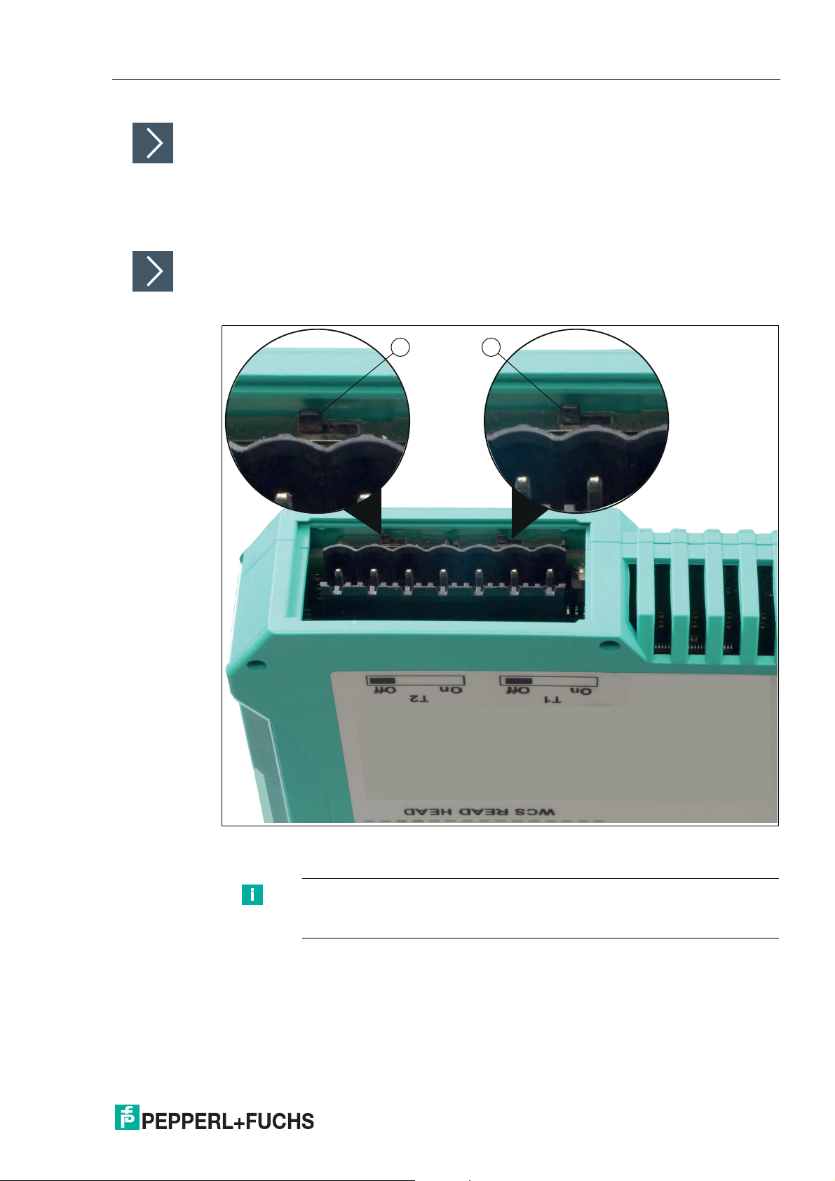
Activating the RS-485 Bus Termination
If the interface module is operated as the first or last physical device in an RS-485 bus or if you
operate one read head on the interface module, a bus termination must be performed on this
interface module.
Figure 4.1 RS-48 5 Bus Termination
Set the T2 slide switch (1) to "On" to activate the bus termination (150 ).
Note
The T1 slide switch (2) has no function and remains in the "Off" switch
position.
2020-03
17
Page 19

WCS-EIG310
Commissioning
4.3 Connection to the Network
The connection to EtherNet/IP is made via the two RJ45 EtherNet/IP P1 and P2 sockets on the
underside of the interface module. The front socket is labeled P1 and the rear socket is labeled
P2. Connect the device to the EtherNet/IP network at the interface with the label "P1" (cable
from m aster) or "P2" (further cable to the next slave).
Note
The cable to the surrounding Ethernet devices must be at least 0.6 m long.
Pinout P1 and P2
Terminal Designation
1 TD+
2 TD-
3 RD+
4 n.c.
5 n.c.
6 RD-
7 n.c.
8 n.c.
Table 4. 3 Terminals of the 8-pin "RJ45 EtherNet/IP" sockets
Transmission line +
Transmission line -
Receive line +
Not connected
Not connected
Receive line -
Not connected
Not connected
Connecting the Device to the Controller
Plug the Ethernet connector into the RJ45 socket. Use a data cable of at least Category 5.
18
2020-03
Page 20

WCS-EIG310
Commissioning
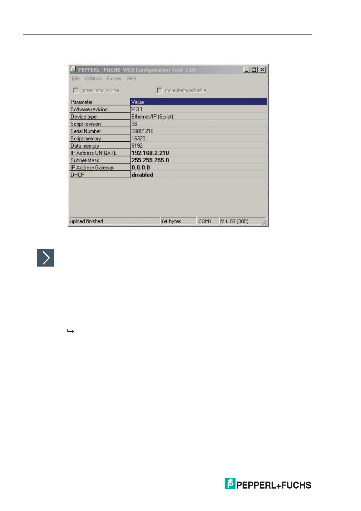
4.4 Setting the IP Address and Subnet Screen
To set the device IP address, the subnet screen, and the gateway IP address, you need the
WCS UGC_PF configuration tool.
Downloading the Software Tool from the Internet
The software tool can be dow nloaded from our website: www.pepperl-fuchs.com .
1.
Simply enter the product name or item number in the Product/Keyword field and click "Search."
2.
Select your product from the list of search results.
3.
Click on the information you require in the product information list, e.g., Software.
A list of all available downloads is displayed.
WCS UGC_PF configuration tool
Unzip the files contained in the ZIP file in a directory of your choice on your computer. Start
UGC_PF.exe and select "Help" from the menu bar. Select "Readme" in the drop-down menu.
Here you will find a brief description of the WCS UGC_PF configuration tool's functions.
1. Set the two rotary switches S4 and S5 on the front panel of the interface module to position
F.
2. Establish a connection between the RS-232 interface of the interface module and your PC.
3. Use the "Upload" function to load the interface module configuration to the software interface.
4. Select the entry to be edited by double-clicking and edit it. Proceed in the same way with
all entries to be changed until the configuration matches your specifications.
5. Save the configuration by clicking "Safe" or "Safe as.".
2020-03
19
Page 21
WCS-EIG310
Commissioning
6. Write the amended configuration into the interface module by clicking "Download."
The configuration has now been changed according to your requirements and saved in the
non-volatile memory of the interface module.
Setting Rotary Switches S4 and S5
1.
Switch off the interface module.
2.
Close the WCS UGC_PF configuration tool.
3.
Disconnect the RS-232 connection between the interface m odule and the PC.
4.
Set the rotary switch S4 to the correct position in accordance with your hardware configuration.
5.
Set the rotary switch S5 to the correct position in accordance with your hardware configuration.
The interface module is now ready to use.
20
2020-03
Page 22
WCS-EIG310
Commissioning
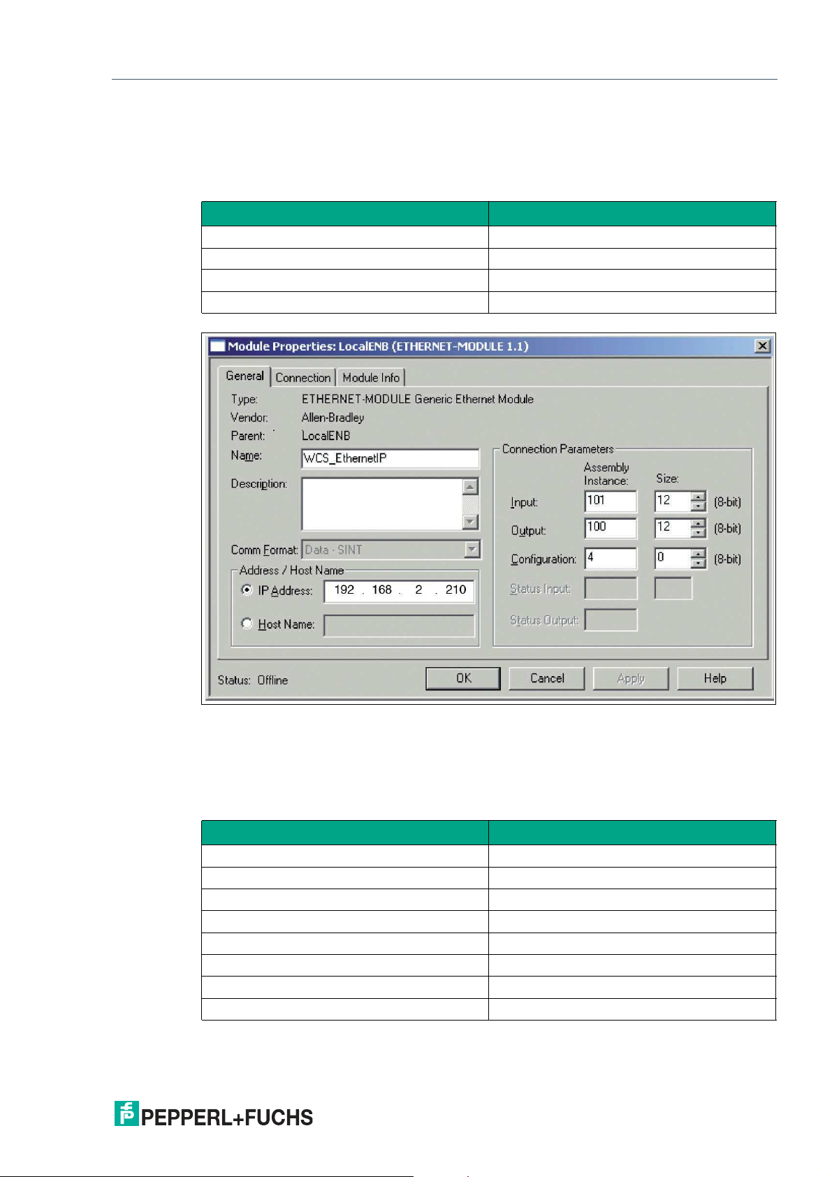
4.5 Network Settings
The interface modul uses implicit messaging. Therefore, any position and speed data is
mapped directly in the controller. The following figure shows the correct setting for integrating
the interface module into the network.
Parameters Value
Input assem bly 101
Output assembly 100
Configuration assembly 4
Minimum RPI 20 ms
Figure 4.2 Network settings
You can enter all values with the exception of the values for "Input Size" and "O utput Size" on
the input screen of your project planning tool. The values for "Input Size" and "Output Size"
depend on the number of readers and the desired data output. You have to adjust these
according to your hardware configuration.
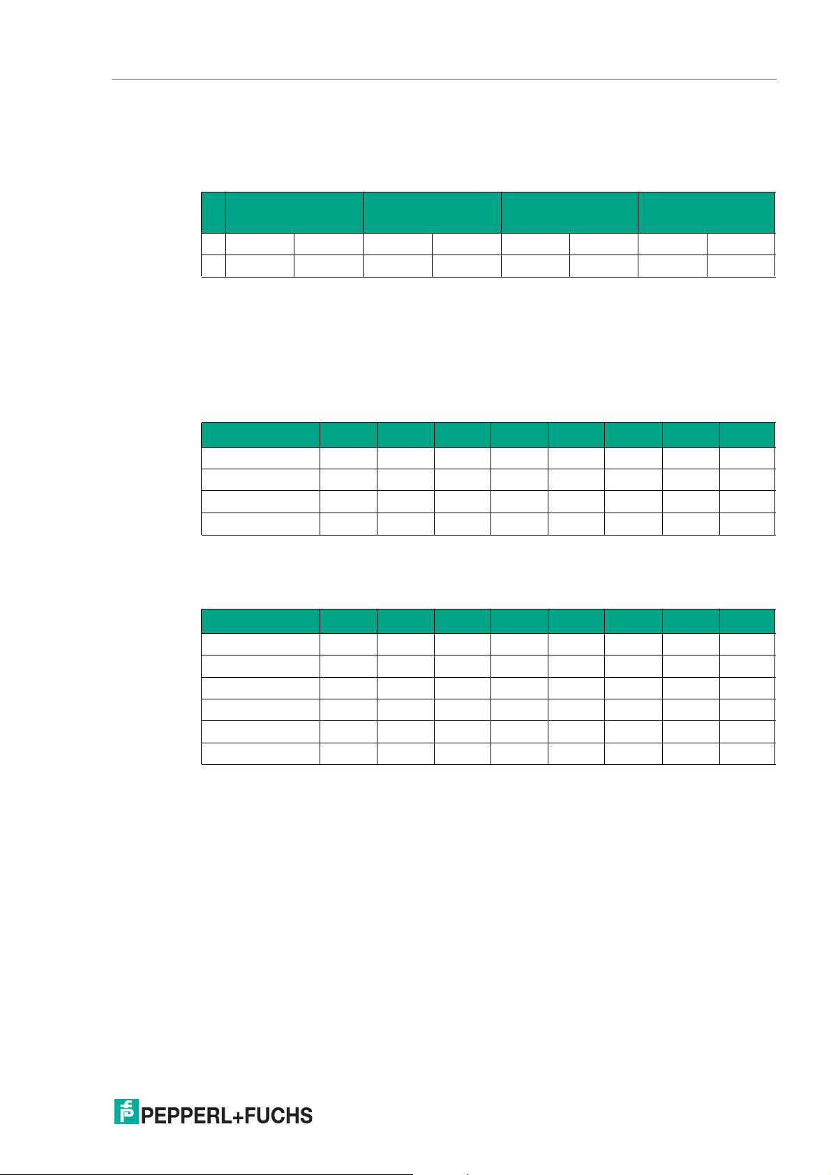
Values for "Input Size" and "Output Size"
Hardware configuration "Input Size" and "Output Size"
1 reader 4 bytes
2 readers 8 bytes
3 readers 12 bytes
4 readers 16 bytes
1 reader with velocity output 6 bytes
2 readers with velocity output 12 bytes
3 readers with velocity output 18 bytes
4 readers with velocity output 24 bytes
Example:
2020-03
21
Page 23

WCS-EIG310
Commissioning
You have connected three readers to the interface module and want to use the velocity output.
Enter the value 18 in both fields "Input Size" and "Output Size".
22
2020-03
Page 24
WCS-EIG310
Communication with WCS read heads
5 Communication with WCS read heads
5.1 Request Byte for Read Heads
Read head address 3Read head address 2Read head address 1Read head address
Bit
F0=0: The read head sends the position data to the interface module. This standard function is
automatically active after commissioning.
F0=1: The read head sends the results of the diagnostic function.
5.2 Data Format for Modules
In "only Position" operating mode, 4 bytes are reserved for each WCS reader.
7 6 5 4 3 2 1 0
0 F0 0 F0 0 F0 0 F0
0
Bit 7 6 5 4 3 2 1 0
Byte 0
Byte 1
Byte 2
Byte 3
Table 5.1 Data format for each connected WCS reader in "only Position" opera ting mode, reader
address = 0...3
0 0 0 0 0 P18 P17 P16
P15 P14 P13 P12 P11 P10 P09 P08
P07 P06 P05 P04 P03 P02 P01 P00
0 0 0 DB ERR OUT A1 A0
In "Position and Speed" operating mode, 6 bytes are reserved for each WCS reader.
Bit 7 6 5 4 3 2 1 0
Byte 0
Byte 1
Byte 2
Byte 3
Byte 4
Byte 5
Table 5.2 Data format for each connected WCS reader in "Position and Speed" opera ting mode,
reader address = 0...3
0 0 0 0 0 P18 P17 P16
P15 P14 P13 P12 P11 P10 P09 P08
P07 P06 P05 P04 P03 P02 P01 P00
0 0 0 DB ERR OUT A1 A0
0 0 0 0 0 0 0 0
0 S06 S05 S04 S03 S02 S01 S00
Pxx: position data, P00 = LSB
Sxx: speed (in multiples of 0.1 m/s), S00 = LSB
Example: Byte 5 = 00011011 = 27, corresponds to 2.7 m/s
A1, A0: reader address, 00 = WCS reader address #1
DB: pollution display, 1 = cleaning necessary
OUT: code rail loss, 0 = code rail recognized
ERR: error display, error code (LEDs)
2020-03
21
Page 25

WCS-EIG310
Communication with WCS read heads
Address bits A1 and A0
A1 A0 Reader address
0 0
0 1
1 0
1 1
Status bits
DB ERR OUT Description
0 0 0
0 0 1
1 0 0
1 0 1
X 1 X
Reader address 0
Reader address 1
Reader address 2
Reader address 3
Optical state
of WCS reader
Current position value binary coded in P00...P18 Good
WCS reader outside of the code rail, not a position
Good
value
P0...P18=0: WCS reader partly outside the code rail
P0=1, P2...P18=0: WCS reader completely outside
of the code rail
Current position value binary coded in P00...P18 Poor
No position value, WCS reader outside of the code
Poor
rail
No position value, error message from WCS reader,
-
error number binary coded in P00...P18
22
2020-03
Page 26
WCS-EIG310
WCS
WCSbyte1
WCSbyte2
WCSbyte3
WCSbyte4
WCSbyte5
WCSbyte6
Position
Speed
Last_Error
WCS1
WCS_EthernetIP:I.Data[0]
??
WCS_EthernetIP:I.Data[1]
??
WCS_EthernetIP:I.Data[2]
??
WCS_EthernetIP:I.Data[3]
??
WCS_EthernetIP:I.Data[4]
??
WCS_EthernetIP:I.Data[5]
??
0
0
0
Position and speed of WCS when using ...
<-<-<--
WCS
OUT
ERR
DB
SST
Appendix
6 Appendix
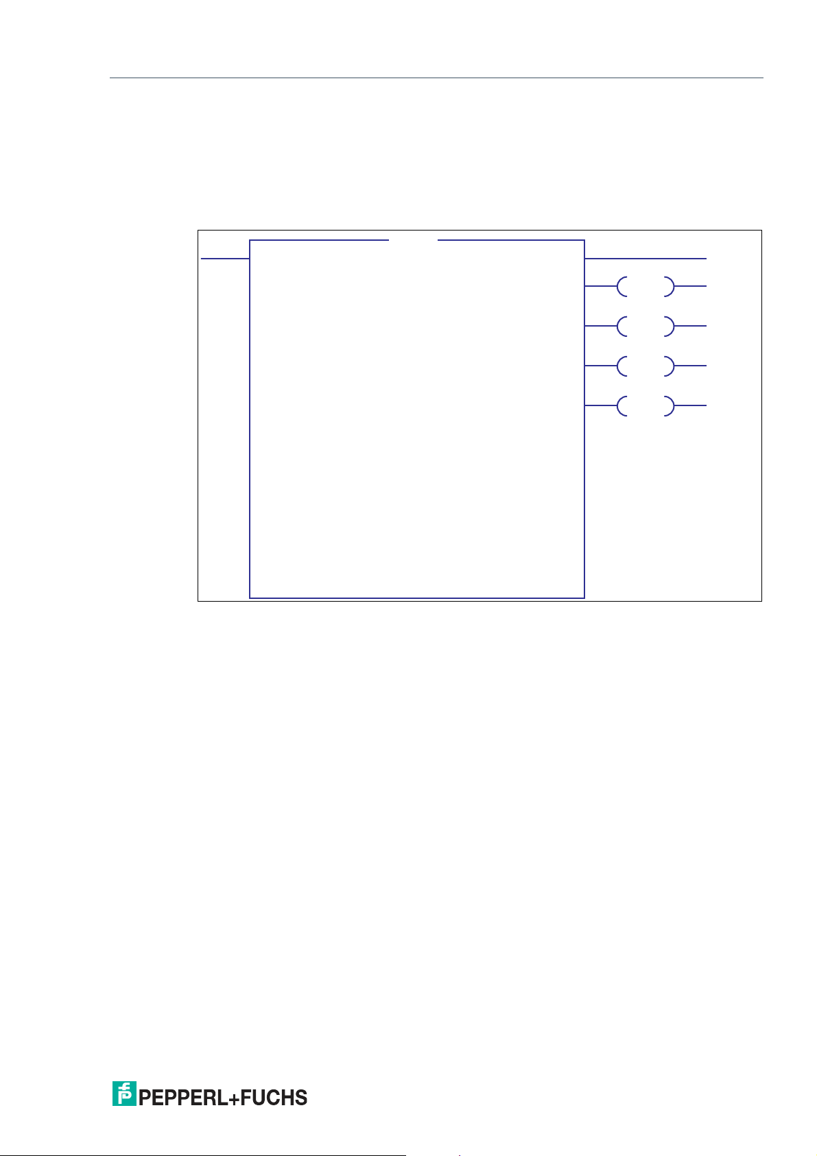
6.1 Software Tool for RSLogix 5000, V15, and V17
This small tool divides the 4 or 6 byte long messages of each WCS read head into the position
values, the speed values, and diagnostic information.
• Position: position data of the read head
• Speed: speed of the read head = speed value x 0.1 m/s
• Last Error: If an error bit is active, it will appear here. It can be reset by the user.
• SST: Status bit speed, usually "0". "1" when an invalid speed value occurs.
• Out: Code rail outside of read head range.
• ERR: An error has occurred. Check "Last Error" for details
• DB: dir ty lens system. Please clean the scanning system with a soft, damp cloth without
cleaning additives.
2020-03
23
Page 27
WCS-EIG310
Reading head
Interface or control
(PLC)
Appendix
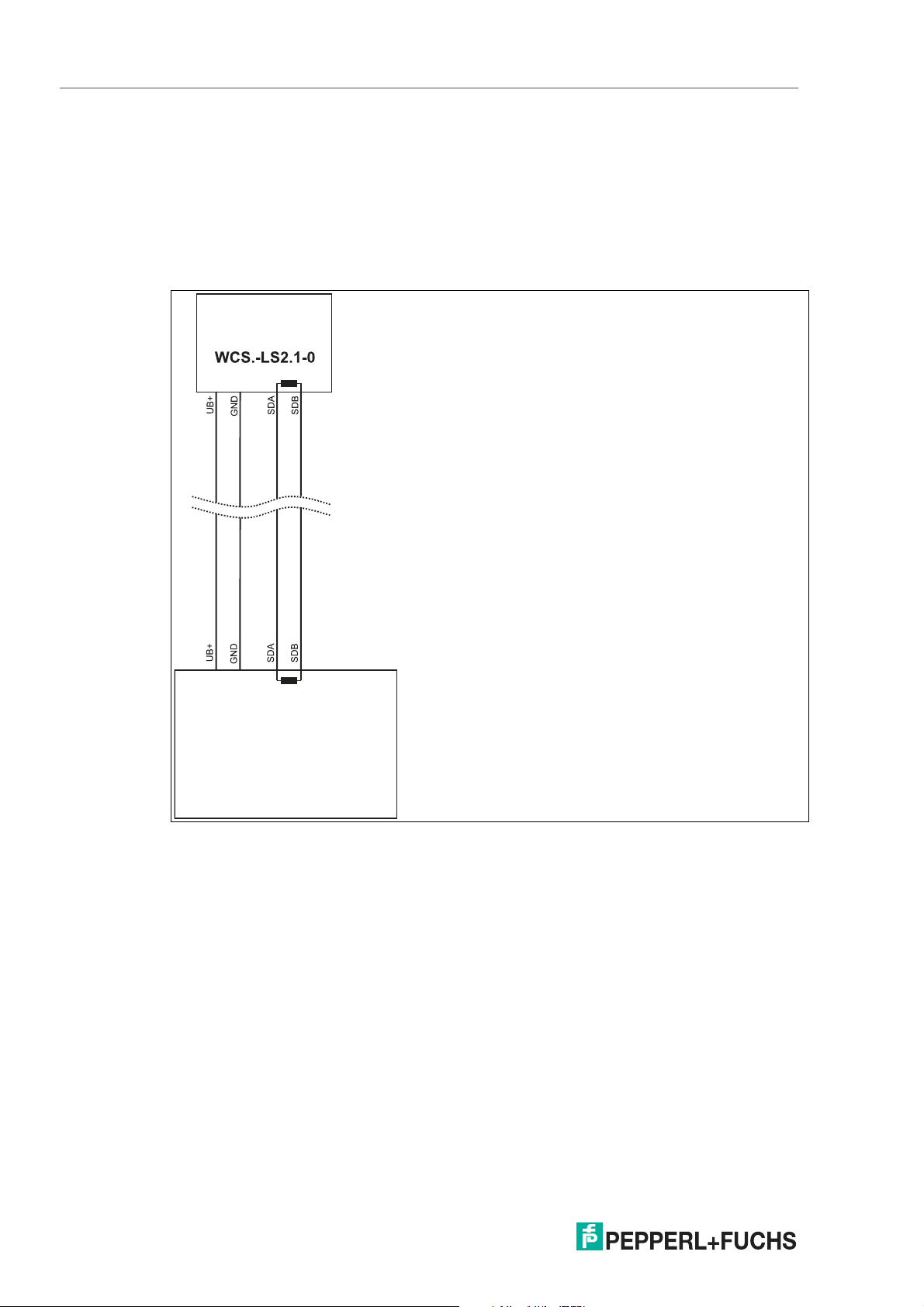
6.2 Cable Routing in the RS-485 Bus
The data cables must always form an in-line connection between the first and the last node.
This in-line connection must end with a terminator.
The RS-485 terminators are integrated in the WCS readers and can be switched on and off
with the interface module.
If only one WCS reader is connected, one device is connected at the beginning and one
device is connected at the end of the data line.
24
Figure 6.1 Connection of on e reading head
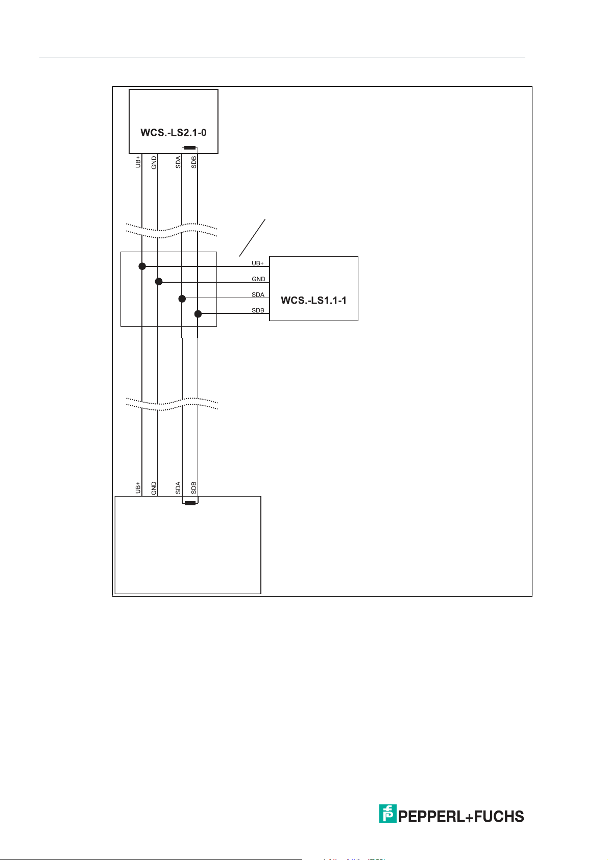
If two WCS readers are connected to one interface module, there are two wiring versions:
• Version A:
One WCS reader is located at the beginning and one WCS reader at the end of the data
line. For both WCS readers, the RS-485 terminator is activated. The interface module is
located between these two readers and does not have an RS-485 terminator. Each WCS
reader is connected to the interface module by a separate data cable.
2020-03
Page 28

WCS-EIG310
Interface or control
(PLC)
Reading head
Reading head
Appendix
Figure 6.2 Connection of two reading heads, Version A
• Version B:
The interface module is located at the beginning of the data line; one WCS reader is
located at the end of the data line. Both need the RS-485 terminator. The second WCS
reader is connected to the line connection between the interface module and the first
WCS reader through a short spur (length <1 m). Use a bus terminal to connect the spur.
2020-03
25
Page 29
WCS-EIG310
Reading head
Reading head
Interface or control
(PLC)
Spur line (max. 1 m)
Bus terminal
Appendix
Figure 6.3 Connection of two reading heads, Version B
The wiring version used depends on which is best suited for the application. If three or four
WCS readers are used on the same interface m odule, connect these using spurs as shown in
variant B.
26
2020-03
Page 30

WCS-EIG310
Appendix
6.3 Data Cable
A shielded data cable with twisted-pair cores is used for the electrical connection. Pepperl+Fuchs can supply suitable preassembled M12 single-ended female cordsets () or fieldattachable M12 female connectors and data cables.
Data Cable WCS-DC*
There are two types of data cable available:
• WCS-DCS for stationary cable routing
• WCS-DCF for routing trailing cables and drag chains.
The data cables are twisted pairs and have a tinned copper braided shield. The braided shield
surrounds all wire pairs. The parameters of the data cables suitable for RS-485, SSI, and
CANopen data transfer are listed in the table below.
Capacitance (core-core) 120 pF/m 60 pF/m
Cross section
Number of cores 6 (3 x 2) 6 (3 x 2)
External diameter 5.8 mm 7.5 m m
Temperature range -40 ... 80 °C -40 ... 70 °C
WCS-DCS WCS-DCF
0.14 mm
2
0.25 mm
2
Cable Routing
The basic prerequisite for uninterrupted data transfer is that the data cables are routed in such
a way that any coupling of electromagnetic fields and interference is excluded. For EMC-compliant cable routing, it is necessary to divide the cables into cable groups and route these
groups separately.
Group A
• Shielded data cable (including analog)
• Unshielded cable for DC and AC voltages 0 ... 60 V
• Shielded cable for DC and AC voltages 0 ... 230 V
• Coaxial cables for monitors
Group B
• Unshielded cable for DC and AC voltages 60 ... 400 V
Group C
• Unshielded cable for DC and AC voltages greater than 400 V
Shielding Cables
The shielding of cables is required to suppress electromagnetic interference. Establishing a
low resistance or low impedance connection with the protective conductor is a particularly
important factor in ensuring that these interference currents do not become a source of interference themselves.
The WCSB2B and WCS3B read heads have no connection option for the cable shield. The
cable shield is connected to the plant potential in the switch cabinet with low resistance (large
area). In the case of high electromagnetic interference, it is advisable to connect the shield of
the data cable to the plant potential in the immediate vicinity of the read head with low resistance using a grounding clip.
2020-03
27
Page 31
WCS-EIG310
Appendix
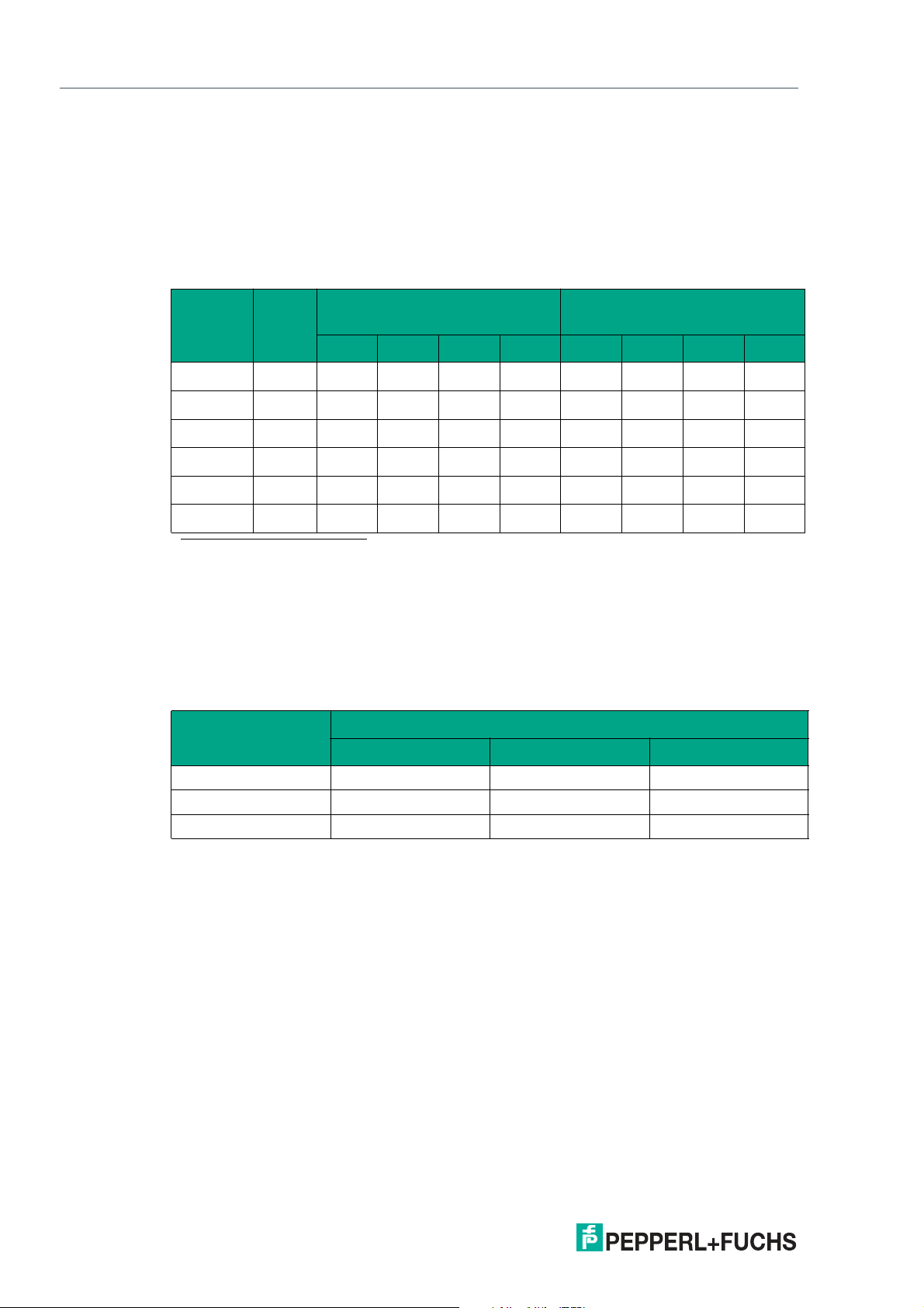
Cable Length
For the RS-485 data transfer path, a four-wire, shielded, twisted pair data cable must be used.
One core pair is used for the supply voltage, and one pair for the RS-485 data connection. The
maximum length of the cable depends on the capacitance of the data cable— core-core—for
data transfer, and on the cross section of the cables for voltage supply to the read heads. For
data transfer, a small core cross section and thus a small cable capacitance is an advantage,
whereas for the voltage supply, the largest possible cross section is required. The table below
shows the possible cable lengths depending on the cable cross section.
Cable
cross
section AWG
2
0.14 mm
0.22 mm
0.25 mm
0.28 mm
0.34 mm
0.50 mm
1. American Wire Gauge, a system commonly used in North America for the specification of wire diameters in electrical
engin eering .
~ 26 200 m 110 m 70 m 50 m 15 m 10 m 7 m 5 m
2
~ 24 320 m 170 m 110 m 80 m 30 m 15 m 10 m 7 m
2
- 350 m 190 m 130 m 90 m 35 m 17 m 12 m 8 m
2
- 400 m 220 m 150 m 110 m 40 m 20 m 15 m 10 m
2
~ 22 500 m 250 m 180 m 140 m 50 m 25 m 17 m 12 m
2
~ 20 500 m 400 m 270 m 200 m 70 m 35 m 25 m 17 m
Number of read heads without
heater
1
1 2 3 4 1 2 3 4
Number of read heads with
heater
In the calculations, the worst-case scenario was assum ed: All read heads are located at the
end of the data cable. In the case of large cable lengths, and when connecting multiple WCS2
read heads with a heater, 6-wire data cables (3 x 2) can be used. These data cables use two
pairs for the voltage supply (doubling the cable cross section), and one pair for the RS-485 data
line. The table below shows the possible cable lengths depending on the cable capacitance
(core-core). The number of connected read heads is of no significance.
Capacitance
(core-core)
RS-485 interface
19.2 kb 62.5 kb 187.5 kb
60 pF 500 m 500 m 300 m
90 pF 500 m 450 m 275 m
120 pF 500 m 400 m 250 m
28
2020-03
Page 32

WCS-EIG310
Appendix
Cable Overview
The cable types listed below represent a selection of the types available from Pepperl+Fuchs.
You can find additional cable types on our website.
Note
For customizable cables, observe the cable length restrictions specified by the interface
specifications. Refer to the relevant interface chapters for m aximum cable length
recommendations.
RS-485 (LS1xx*, LS2xx*)
Cable Description
Field attachable cable
V15-G-2M-PUR-ABG M12 single-ended female cordset, 5-pin, straight, 2 m PUR cable,
shielded
V15-G-5M-PUR-ABG M12 single-ended female cordset, 5-pin, straight, 5 m PUR cable,
shielded
V15-G-10M-PURABG
Field attachable single-ended female cordsets and available by the meter
V15-G-ABG-PG9 M12 single-ended female cordset, 5-pin, straight, field attachable,
V15-G-ABG-PG9-FE M12 single-ended female cordset, 5-pin, straight, field attachable,
V15-G-PG9 M12 single-ended female cordset, 5-pin, straight, field attachable
V15-W-PG9 M12 single-ended female cordset, 5-pin, angled, field a ttachable
WCS-DCS
WCS-DCF
M12 single-ended female cordset, 5-pin, straight, 10 m PUR cable,
shielded
shielded
shielded with grounding terminal
Available by the meter, 6-pin data cable + shield, 0.14 mm
3 x 2 twisted core pair
Available by the meter, 6-pin data cable + shield, 0.25 mm
3 x 2 twisted core-pair, suitable for drag chains
2
2
2020-03
29
Page 33

Pepperl+Fuchs Quality
Download our latest policy here:
www.pepperl-fuchs.com/qualit y
© Pepperl+Fuchs · Subject to modifications
www.pepperl-fuchs.com
Printed in Germany / DOCT-6396
 Loading...