

Page 1

FACTORY AUTOMATION
MANUAL
WCS
position encoding system
Mechanics
Page 2

WCS position encoding system
With regard to the supply of products, the current issue of the following document is ap-
plicable: The General Terms of Delivery for Products and Services of the Electrical Indus-
try, published by the Central Association of the Electrical Industry (Zentralverband
Elektrotechnik und Elektroindustrie (ZVEI) e.V.) in its most recent version as well as the
supplementary clause: "Expanded reservation of proprietorship"
Page 3

WCS position encoding system
1 Introduction................................................................................. 5
2 Declaration of conformity .......................................................... 6
2.1 CE conformity....................................................................................... 6
3 Safety........................................................................................... 7
3.1 Symbols relevant to safety.................................................................. 7
3.2 General safety instructions ................................................................. 7
4 Product Description ................................................................... 8
4.1 Functional Description ........................................................................ 8
4.2 Application areas ............................................................................... 10
5 Readers ..................................................................................... 13
5.1 Mounting ............................................................................................. 16
5.2 Plastic Lenses .................................................................................... 18
6 Code Rail ................................................................................... 20
6.1 Grounding the Code Rail................................................................... 21
6.2 Clamping Fixture for the Stainless Steel Code Rail ........................ 21
6.3 Identification....................................................................................... 22
7 Mounting the Code Rail............................................................ 24
7.1 Mounting the Code Rail with Mounting Brackets............................ 26
7.1.1 Mounting the Code Rail on a Straight Route .................................... 29
7.1.2 Mounting the Code Rail on Curves .................................................. 30
7.2 Mounting WCS2 Code Rail with the Aluminum Profile System ..... 31
7.3 Rail Holders ........................................................................................ 35
7.3.1 Adapter Plates for Profile Rails......................................................... 36
7.3.2 Mounting the Code Rail ................................................................... 39
7.3.3 Fixed Points ..................................................................................... 41
7.3.4 The Guide Trolley............................................................................. 42
7.3.5 Grounding the Aluminum Profile System.......................................... 44
3
Page 4

WCS position encoding system
7.4 Mounting WCS3 Code Rail with the Aluminum Profile System .....45
7.4.1 Rail Holders......................................................................................48
7.4.2 Adapter Plates for Profile Rails ......................................................... 49
7.4.3 Mounting the Code Rail....................................................................51
7.4.4 Fixed Points...................................................................................... 52
7.4.5 Vertical Curves .................................................................................54
7.4.6 Interruptions in the Profile Rail..........................................................55
7.4.7 Suspended Mounting with Stainless Steel Code Rail ....................... 55
7.4.8 Grounding the Aluminum Profile System .......................................... 56
7.4.9 Integration of the WCS Code Rail in Conductor Lines ......................56
4
Page 5
WCS position encoding system
Introduction
1 Introduction
Congratulations
You have chosen a device manufactured by Pepperl+Fuchs. Pepperl+Fuchs develops,
produces and distributes electronic sensors and interface modules for the market of
automation technology on a worldwide scale.
Symbols used
The following symbols are used in this manual:
Note!
This symbol draws your attention to important information.
Handling instructions
You will find handling instructions beside this symbol
Contact
If you have any questions about the device, its functions, or accessories, please contact us at:
Pepperl+Fuchs GmbH
Lilienthalstraße 200
68307 Mannheim
Telephone: +49 621 776-4411
Fax: +49 621 776-274411
E-Mail: fa-info@pepperl-fuchs.com
2014-10
5
Page 6

WCS position encoding system
Declaration of conformity
2 Declaration of conformity
2.1 CE conformity
This product was developed and manufactured under observance of the applicable European
standards and guidelines.
Note!
A declaration of conformity can be requested from the manufacturer.
2014-10
6
Page 7
WCS position encoding system
Safety
3 Safety
3.1 Symbols relevant to safety
Danger!
This symbol indicates an imminent danger.
Non-observance will result in personal injury or death.
Warning!
This symbol indicates a possible fault or danger.
Non-observance may cause personal injury or serious property damage.
Caution!
This symbol indicates a possible fault.
Non-observance could interrupt devices and any connected facilities or systems, or result in
their complete failure.
3.2 General safety instructions
Responsibility for planning, assembly, commissioning, operation, maintenance, and
dismounting lies with the system operator.
Installation and commissioning of all devices must be performed by a trained professional only.
User modification and or repair are dangerous and will void the warranty and exclude the
manufacturer from any liability. If serious faults occur, stop using the device. Secure the device
against inadvertent operation. In the event of repairs, return the device to your local
Pepperl+Fuchs representative or sales office.
Note!
Disposal
Electronic waste is hazardous waste. When disposing of the equipment, observe the current
statutory requirements in the respective country of use, as well as local regulations.
2014-10
7
Page 8

WCS position encoding system
Product Description
4 Product Description
4.1 Functional Description
The WCS position encoding system consists of two main components:
1. The code rail
The code rail carries information for the absolute code. The code rail is routed parallel to
the track for the material handling equipment and assigns a unique position to every point
on the track. It is possible to route the code rail only at points where positioning is required.
The system allows the code rail to be routed along curves and allows branches to be created. The code rail is built to order and delivered in a bundle. Unless otherwise ordered,
the code rail always starts w ith the position value 0. The maximum length of the code rail
is 327 m (WCS2) or 314.5 m (WCS3). Brackets are available for mounting the code rail.
2. The reader
The U-shaped reader scans the code rail photoelectronically without touching it. Every
0.833 mm (WCS2) or 0.8 mm (WCS3), the reader detects a new position value. After insertion into the code rail, the reader determines the position value without reference or delay. The code rail can be scanned at very high speeds. The scanning is reproducible,
reliable, and independent of temperature fluctuations. The position value can be transferred directly from the reader to the controller via a serial RS485 interface. For connection
to standard interfaces, there is a wide range of interface modules available:
• Parallel
• SSI
• PROFIBUS DP
• DeviceNet
• CANopen
• Ethernet
• InterBus-S
• PROFINET
• MODBUS RTU
Up to four readers can be connected simultaneously to all interface modules with the exception of the SSI interface module.
2014-10
8
Page 9
WCS position encoding system
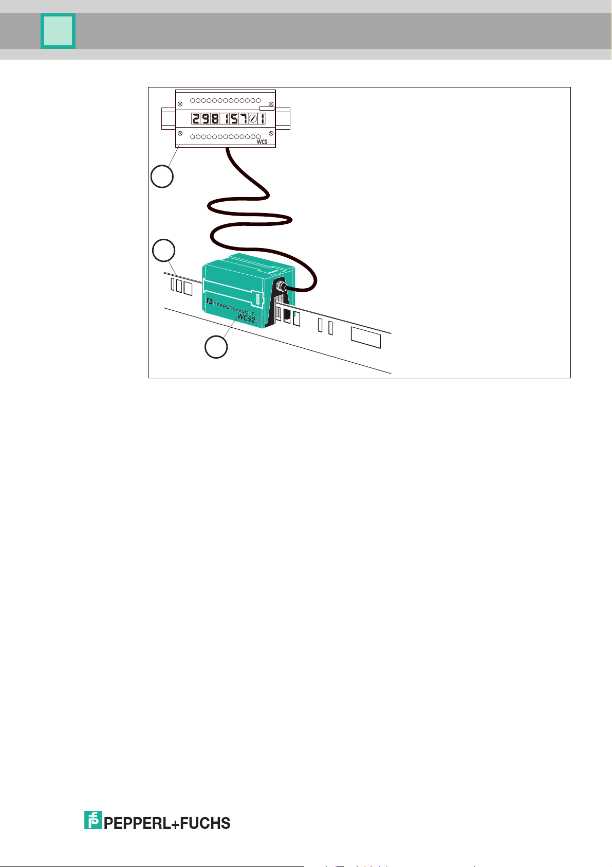
1
2
3
Product Description
1. Interface module
2. Code rail
3. Reader
Properties of the WCS
■
Absolute position encoding system
■
Photoelectric principle (infrared range)
■
Proven and robust
■
Easy to maintain
■
No reference points required
■
No calibration and adjustment work necessary
■
Resistant to power failure
■
Millimeter-precise positioning with absolute repeat accuracy
■
Determination of position value in real time and regardless of temperature fluctuations
■
Guaranteed reading up to a speed of 12.5 m/s
■
High resolution = ±0.4 mm
■
Variable route length: 0.1 m to 327 m
■
Coding system also suitable for curves with up to 0.5 m radius
■
A wide variety of applications, such as stock feeders, trolleys, monorail conveyors,
galvanic plants, automatic and slewing cranes, as well as elevators
■
Various mounting systems available for installing the code rail
■
Connection to any controller possible, either directly or via interface module
■
Connectivity to many fieldbus systems available
■
Support during commissioning and maintenance with extensive system diagnostics
options
2014-10
9
Page 10
WCS position encoding system
Product Description
■
High functional reliability as a result of permanent self-diagnostics
■
Contamination warning
■
Optional heating for ambient temperatures down to -40 °C
■
Digital output of an adjustable limit speed (optional)
4.2 Application areas
The WCS can be used anywhere where material handling equipment has to be positioned
precisely. The functional principle of the WCS enables it to be used in a diverse range of
applications, such as:
■
Interruptions in the code rail (lane changes, track switches)
■
Applications with curves and circular paths
■
Use of multiple vehicles in a row
Due to the larger tolerances of the reader in relation to the code rail, in most applications the
WCS3 system can be used. In some circumstances, however, it is advantageous to use the
WCS2 in conjunction with the aluminum profile system. Here are some exam ples from the
variety of application options:
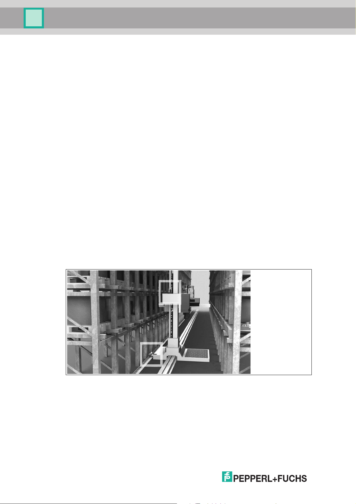
Stock Feeders (High-Bay Warehouse)
Trolleys, lifting gear, and transversing carriages are each positioned with one reader. The
positioning is independent of the length of the code rail and always absolutely reproducible. For
new high-bay warehouses we recommend the WCS3 system. For retrofits in older warehouses,
it may be beneficial to use the WCS2 in conjunction with the aluminum profile system:
■
Easy to retrofit
■
High mechanical tolerances between the measuring system and moving carriages
possible
■
Decoupling of vehicle vibrations
10
Figure 4.1 Stock feeder (high-bay warehouse)
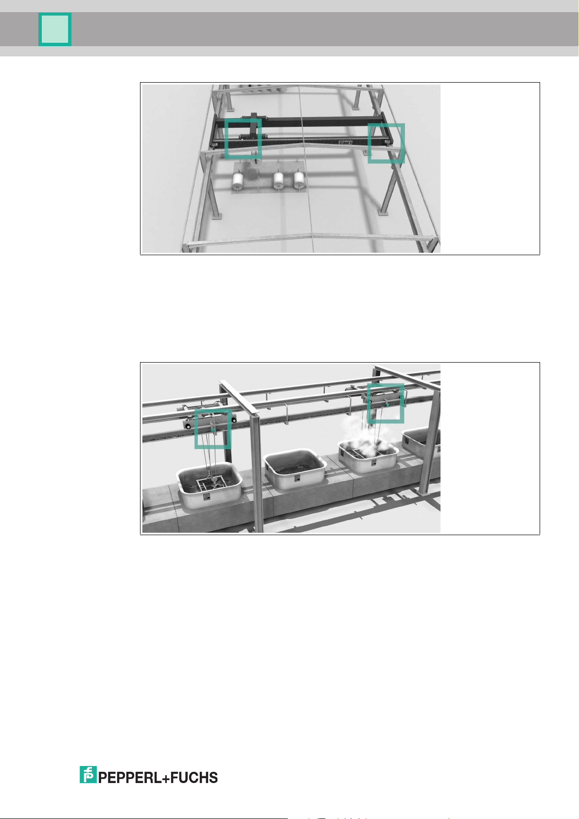
Automatic Cranes
Automatic cranes are a typical application for the WCS2 in conjunction with the aluminum
profile system. The crane is positioned using one reader each for the crane and the trolley
movement. At each point, the guide trolley ensures the optimum position of the reader in
relation to the code rail and decouples any vibrations from the crane track. Optional cleaning
brushes for the code rail can be attached to the guide trolley. This means that the WCS2 can be
used in a very dusty environment, su ch as in cement works or foundries.
2014-10
Page 11
WCS position encoding system
Product Description
Figure 4.2 Automati c crane
Galvanic plants
One or more vehicles moving in a line along a straight route. The vehicles bring the material to
be galvanized into the corresponding bath automatically. The high and adaptable light output of
the readers has enabled the WCS position encoding system to perform extremely well even
under these difficult conditions. In addition to the WCS3 system, the WCS2 with the aluminum
profile system, which is also available powder-coated, can be used.
Figure 4.3 Ga lvanic plant
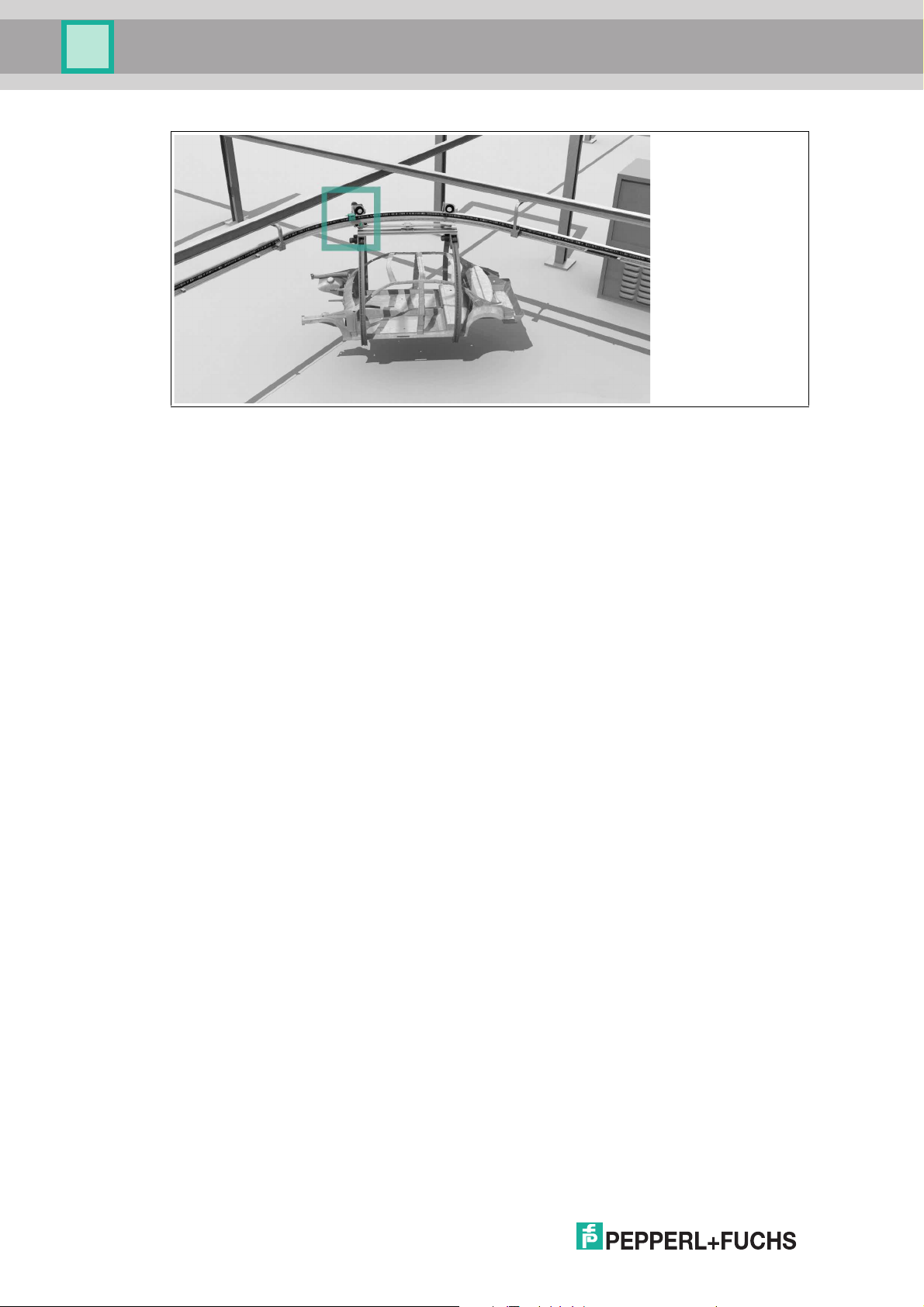
Overhead Conveyors
Many vehicles have to be positioned on a circular track— the WCS offers the optimal solution
for this. Branches (track switches) and curves can be created. The WCS3 is particularly wellsuited for this task. After a power failure, the current position of the vehicle is transferred to the
controller immediately; the vehicle does not have to be moved. The WCS can also be used for
distances longer than 314 m.
2014-10
11
Page 12
WCS position encoding system
Product Description
Figure 4.4 Overhea d conveyor
12
2014-10
Page 13
WCS position encoding system
129
10
75
40
38
33
75
115
57
M12 x 1
Readers
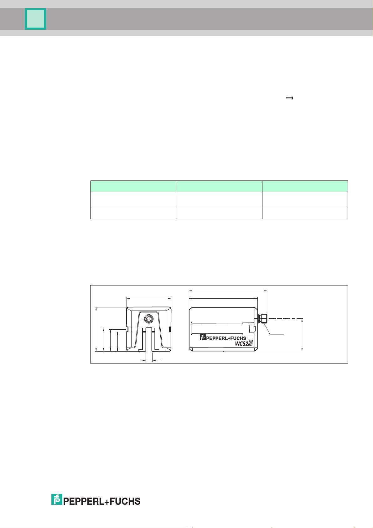
5 Readers
The reader housing is m ade from a robust plastic and has IP54 protection. The product
contents include the mounting bracket for mounting the reader. On the inside of the reader
there are easily rem ovable, transparent plastic lenses that protect the reading area against dirt
and damage. Identification notches can be found on these lenses. The notches are used for
adjustment of the zero point for the vertical play of the reader (= Z-axis). see image on page
14. The reference point is the top edge of the code rail. Within specified tolerances, the reader
may move around this reference point: if the vertical play on the Z-axis is exceeded, the reader
repor ts "OUT" to the controller (reader outside the code rail). The tolerances for the lateral play
on the Y-axis result from the gap width of the reader. The positions are reliably determined up
to a minimum of 500 m m for both an inclined position in the vertical direction and in the
horizontal direction, as well as in curves. If the position value cannot be determined, for
example due to contamination of the optical system, the reader reports a unique error code.
From a technological point of view, the WCS2B and WCS3B readers are very similar. The
resolution and the signals to the interface are almost identical. However, there are differences
in the mechanical systems and in the accessories.
Resolution ± 0.42 mm
v
max
WCS2B WCS3B
± 0.40 mm
1200 pos./m
1250 pos./m
12.5 m/s 12.5 m/s
WCS2B
WCS2B readers have a gap width of only 10 mm. This close proximity between the emitter and
receiver provides high contaminate burn-through power. This makes the WCS2B reader
suitable for ver y dirty environments such as galvanizing plants, foundries, and steel mills. An
optional guide trolley and the WCS2B rail system are specially designed for operation with
imprecise mechanical connections and w here vibrations occur, for example, with automatic
cranes.
Figure 5.1 WCS2B dimen sional drawing
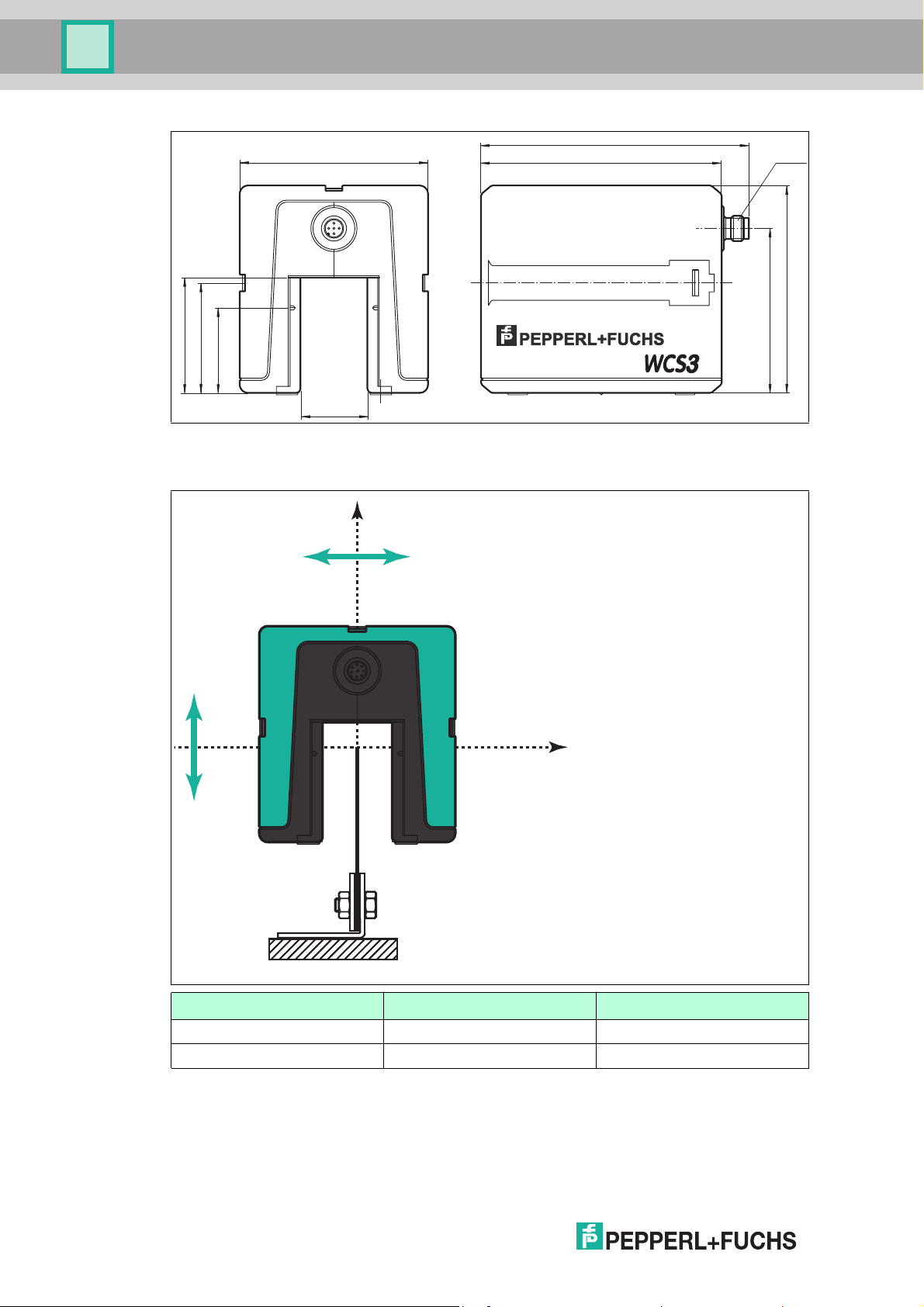
WCS3B
WCS3B readers have a gap width of 31 mm. This results in a greater tolerance when mounting
the reader and aligning it in relation to the code rail. WCS3B systems are ideal for monitoring
conveyor belts and automated warehouse and lifting systems.
Special features of the WCS3B readers include the status LEDs for the alignment and
performance display, an optional "overspeed" output, and an optional 7-segment display for
position and diagnostic data.
2014-10
13
Page 14
WCS position encoding system
53
40.5
99
78.5
55
90
128
115
31
M12 x 1
B
Y
Z
Readers
Figure 5.2 WCS3B dimen sional drawing
Tolerance for Y- and Z-axis
WCS2B WCS3B
Y-axis ± 5 m m ± 15.5 mm
Z-axis ± 5 m m ± 14 mm
14
2014-10
Page 15
WCS position encoding system
Y
Z
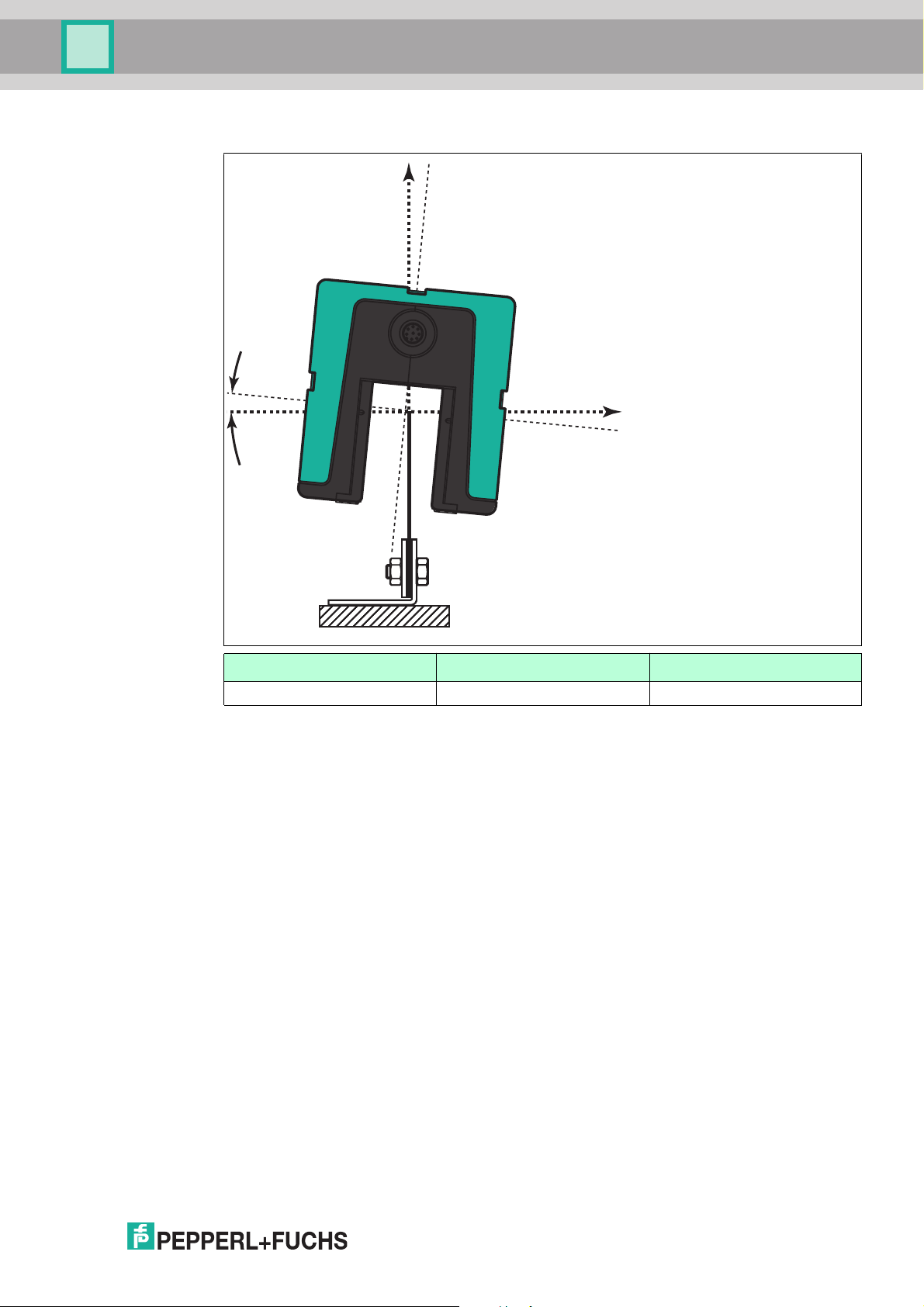
Readers
Tolerance for inclined position α
WCS2B WCS3B
α ±10° ±10°
2014-10
15
Page 16
WCS position encoding system
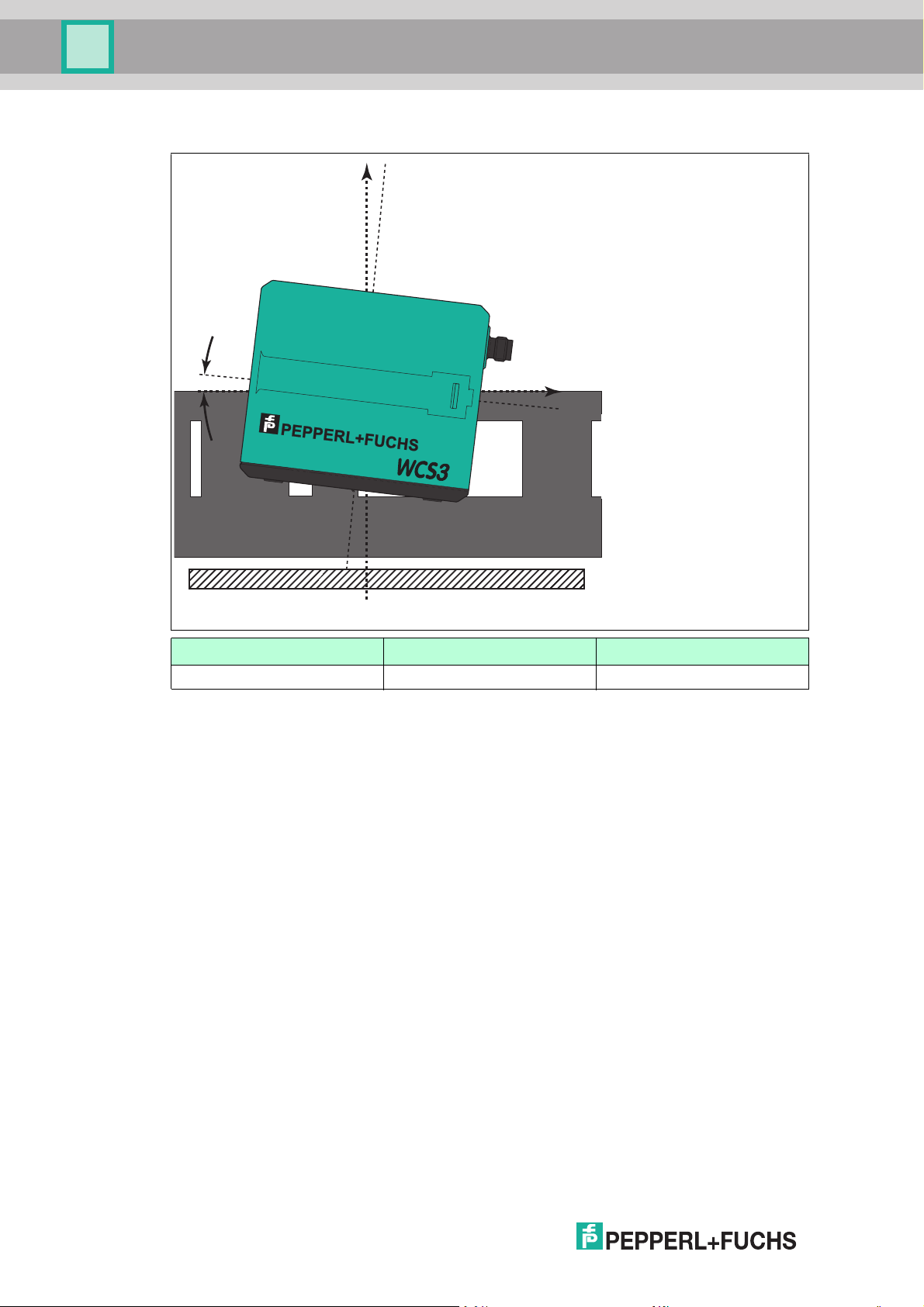
X
Z
β
B
Readers
Tolerance for inclined position β
5.1 Mounting
WCS2B WCS3B
β ±5° ±5°
As a rule, the reader is mounted on the vehicle. However, the reader can also be mounted
stationary. A code rail unit can also be mounted on the carriage (vehicle identification).
A special mounting bracket is supplied with the reader. This is mounted on the carriage. If the
WCS2 is used with an aluminum profile rail system and guide trolley, the mounting bracket is
already installed in the guide trolley. On three sides of the reader housing, dovetail grooves are
integrated with a quick-action lock. If required, the reader is pushed onto the base module of
the mounting bracket via one of these grooves and engaged w ith a spring tongue. This quickaction lock makes it easy to m ount and quickly replace the reader when necessary without any
adjustment work. The installation location of the reader is arbitrary. The reader is not sensitive
to extraneous light.
16
2014-10
Page 17
WCS position encoding system
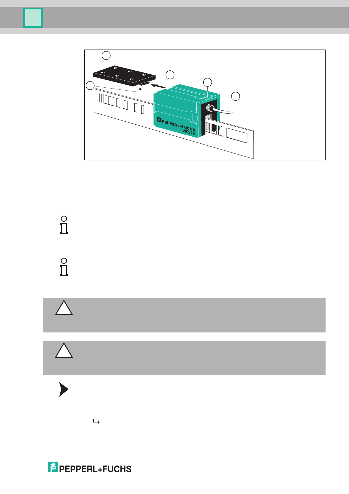
1
2
3
4
5
Readers
1. Reader
2. Quick-action lock
3. Groove
4. Mounting base
5. Base module with spring tongue
Note!
Mounting Direction
Mount the reader so that the electrical connecting plug points in the direction of the ascending
position values on the code rail.
Tip
Securing the Mounting Bracket
Plan elongated holes in the design of the end stop on the carriage. These allow you to correct
the position of the mounting bracket and the reader during mounting.
Caution!
Interference from strong sunlight
When planning the plant, make sure that no strong sunlight can shine directly into the reader
gap.
Caution!
Interference from contamination
When installing the reader, make sure that the reader gap is protected against dirt and any
vapors. This allows for long-term, trouble-free function.
2014-10
1. Secure the mounting bracket to the carriage with size M4 screws.
2. Slide the dovetail groove on the reader onto the base module of the mounting bracket. In the
end position, the spring tongue engages audibly in the quick-action lock.
The reader is mounted.
3. For dismounting, unlock the spring tongue with a screwdriver.
4. Push the reader off the base module of the mounting bracket.
17
Mounting and Dismounting with the Mounting Bracket
Page 18
WCS position encoding system
12.5 40 40
105
40
58
3
6
9.5
ø 4.5
3
6
9.5
ø 8
Readers
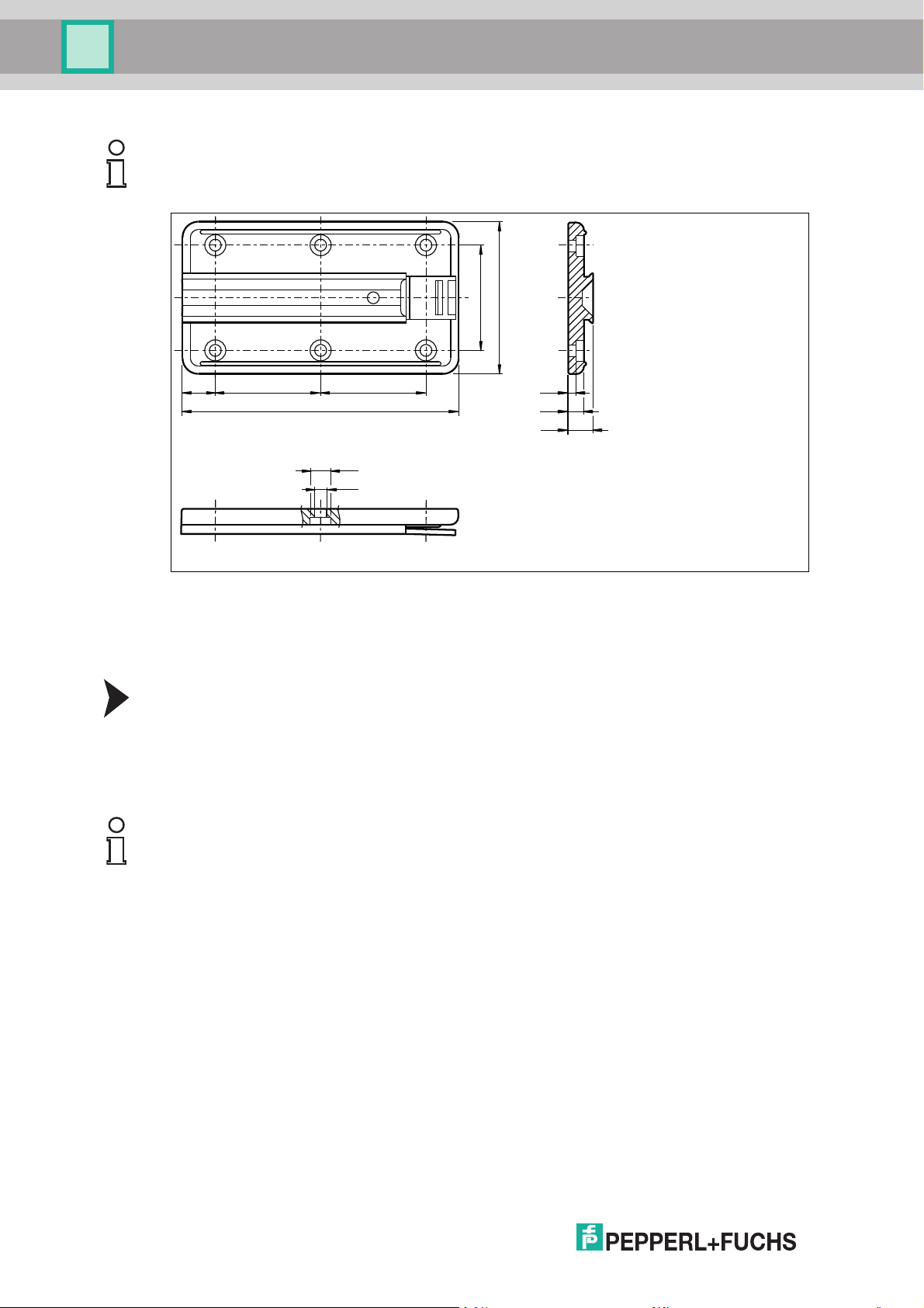
Note!
The mounting bracket is identical for all readers.
Figure 5.3 WCS-MP1 mounting bracket
5.2 Plastic Lenses
In the event of damage or contamination, you can replace the reader's plastic lenses.
Replacing the Plastic Lenses
1. Loosen two cross-head screws on each lens.
2. Remove the lens.
3. Slide the new lens into the intended position on the inside of the reader gap.
4. Secure the lens with the cross-head screws. The maximum torque is 0.8 Nm.
Tip
Always replace the lenses in pairs and also replace the seals.
The plastic lenses are available in pairs as spare parts.
18
2014-10
Page 19

WCS position encoding system
Readers
Model number for two lenses
with seals
WCS2B WCS3B
WCS2-PL2 WCS3B-PL2
2014-10
19
Page 20

WCS position encoding system
Code Rail
6 Code Rail
The absolute code rail is different for the WCS2 system and WCS3 system Therefore, the code
rails are not interchangeable. For WCS3, the height of the code rail is always 70 mm; for
WCS2, the rail can be su pplied at a height of 55 mm or 70 mm. Two different materials that
have proven successful in practice are available for the code rail: plastic laminate and stainless
steel. The code rail is delivered in a coil. Unless otherwise ordered, the code rail always starts
with the position value 0.
Laminate Code Rail
The black laminate code rail consists of a special polyester laminate. It is characterized by
good physical and chemical properties and has a low weight. The material has a high tensile
strength and behaves neutrally to oils, greases, and solvents. Because of its good resistance to
acids, alkalis, and aggressive gases, the laminate code rail is suitable for use in electroplating.
The laminate code rail is delivered with mounting holes as standard (WCS3-CS70-L1, see also
the drawing below). If you use a bracket system to mount the code rail, use of a code rail
without mounting holes is recommended (WCS3-CS70-L0).
The laminate code rail can be used in a temperature range from -40 °C ... 60 °C. Temperatures
above 70 °C lead to material deformation.
The specific thermal expansion coefficient is approximately 2.8 x 10⁻⁵ K-1.
Due to its material properties, the laminate code rail must not be mounted at temperatures
below 10 °C. In applications with large temperature fluctuations (> 50 K), we recomm end the
use of the stainless steel code rail.
Warning!
Sanding dust
When mounting the laminate code rail, make sure that sanding dust from current collectors
cannot fall directly onto the surface of the code rail. When mounting the laminate code rail on
the side, mount it above the sanding lines.
Stainless Steel Code Rail
The stainless steel code rail is m ade from corrosion-resistant spring steel. It is rust-free and is
characterized by high mechanical stability and low thermal expansion.
The stainless steel code rail can be used in the temperature range -40 °C ... 80 °C.
The specific thermal expansion coefficient is 1.6 x 10⁻⁵ K-1.
Caution!
Risk of injury
Wear protective gloves when mounting the stainless steel code rail.
20
2014-10
Page 21

WCS position encoding system
1
1
Code Rail
WCS2B code rail
1. 6-digit position identifier
Dimensions [mm] a b c
Code rail 55 x 0.5 55 7.5 25
Code rail 70 x 0.5 70 15 41
WCS3B code rail
1. 6-digit position identifier
6.1 Grounding the Code Rail
When installing the WCS code rail made from lam inate or stainless steel, make sure that the
code rail is connected with the plant potential ever y 30 m with low resistance.
6.2 Clamping Fixture for the Stainless Steel Code Rail
Using the clamping fixture prevents the stainless steel code rail from warping due to
temperature fluctuations after mounting. It also makes mounting easier.
Note!
Pretensioning of the stainless steel code rail is not necessary for system function.
Pretensioning is useful only if large temperature fluctuations can occur within a short time.
The clamping fixture can only be used together with the stainless steel code rail.
Three mounting holes are stamped in a row at the beginning and end of the stainless steel rail.
They are used for screwing on the clamping fixture. There are two options for installing the
clamping fixture:
1. The code rail is fastened at one end and tensioned at the other end with the clamping fixture.
2. The code rail is fastened in the middle and tensioned with the clamping fixture at both
ends. This method is advantageous for longer distances (> 50 m).
2014-10
21
Page 22

WCS position encoding system
Code Rail
WCS-MT1 clamping fixture
Stainless steel code rail Tightening torque
WCS2B, 55 m m 6 Nm
WCS2B, 70 m m 9 Nm
WCS3B, 70 m m 7 Nm
6.3 Identification
In applications where the vehicle num ber is recognized in the plant, special code rail units
known as ID pads are available for the WCS3 system. In these applications, the reader is
generally mounted in a fixed position. The ID pads mounted on the chassis pass through the
reader at certain points in the plant. The controller can use the position value read by the reader
to calculate the integer vehicle number based on a formula. In total, 1260 different ID pads are
available.
Vehicle number = INT((WCS position value - 30) / 312) + 1
In addition to the calculation of the vehicle number, the position value determined by the reader
enables fine positioning of the ID pad in the reader gap and thus exact positioning of the
vehicle.
22
2014-10
Page 23

WCS position encoding system
70
7.5
6.5
12
240 ... 264
19.2 192 19.2
57.5
25.5
XXXX
Code Rail
ID pad WCS3-ID70-M1
Figure 6.1 XXXX = 0001 - 1260
Designation Part number Material
WCS3-ID70-M1
WCS3-ID70-L1
Table 6.1
1)
1)
1)
: When ordering, please specify the desired ID pad number
184073 Stainless steel
184761 Laminate
2014-10
23
Page 24

WCS position encoding system
Mounting the Code Rail
7 Mounting the Code Rail
With continuous position measurement for a route, you have to mount the code rail in one
piece. Depending on the usage conditions, there are various options for securing the code rail:
■
Mounting bracket
■
Aluminum profile rails
Installation position
The installation position of the code rail is arbitrary. When m ounting the code rail, make sure
that all mounting brackets or rail holders of the profile system are at one level. The area on
which the m ounting bracket or rail holders are mounted must be level.
Note!
The following examples show the installation positions with mounting brackets. The installation
positions are equally valid for mounting with the aluminum profile system.
Figure 7.1 Horizontal install ation
24
2014-10
Page 25

WCS position encoding system
Mounting the Code Rail
Figure 7.2 Vertical installation
2014-10
25
Page 26

WCS position encoding system
Mounting the Code Rail
Figure 7.3 Installation on a wall
Figure 7.4 Installation on a ceiling
7.1 Mounting the Code Rail with Mounting Brackets
The bracket system is an easy way to mount laminate or stainless steel code rails. It consists of
brackets for routing the code rail in straight sections, as well as brackets for routing the code rail
on curves and circular paths. The brackets are made from galvanized sheet steel and are
supplied pre-assembled. The mounting brackets for installation of the WCS code rail can be
delivered in three different versions:
26
■
Without fastening screws
■
With fastening screws
■
With fastening screws for mounting in C profile rails
2014-10
Page 27

WCS position encoding system
70
38
26
M6 x 12
6
16
26
6
20
60
90
M4 x 12 3.5 x 6.5
40
24
20
40
ø 6
16
Mounting the Code Rail
Mounting brackets without fastening screws
WCS-MB/WCS-MB-C WCS-MB-B
Designation Part num ber Function/use Support distance
WCS-MB 184236 Bracket for straight
1.25 m
sections
WCS-MB-C 184099 Bracket for straight
1.25 m
sections,
powder coated, stainless
steel clamping screws
WCS-MB-B 184237 Bracket for curve 0.5 m – max. 0.7 m
WCS-MB-R1 215230 End mounting -
WCS-MB-R2 215231 Guide brackets -
2014-10
27
Page 28

WCS position encoding system
M6 x 12
M6 x 12
38
26
83
70
6
16
26
10 x 6
20
206
60
90
Mounting the Code Rail
Mounting bracket with fastening screws
WCS-MB1
Designation Part number Function/use Support distance
WCS-MB1 184098 Bracket for straight
1.25 m
sections
WCS-MB1-B 184100 Bracket for curve 0.5 m – 0.7 m
28
2014-10
Page 29

WCS position encoding system
20
5
20
40
25
M6
M6 x 12
M6 x 12
38
26
83
70
6
60
90
6
16
26
10 x 6
24
83
20
40
5
M6 x 20
20
40
40
M4 x 12 3.5 x 6.2
25
Mounting the Code Rail
Mounting bracket with fastening screws for mounting in C profile rails
30 mm x 32 mm
WCS-MB2/WCS-MB2-C WCS-MB2-B
Designation Part num ber Function/use Suppor t distance
WCS-MB2 184101 Bracket for straight
WCS-MB2-C 184102 Bracket for straight
WCS-MB2-B 184103 Bracket for curve 0.5 m – 0.7 m
7.1.1 Mounting the Code Rail on a Straight Route
Mounting the Code Rail — Straight Route
1. Mount the mounting brackets at an offset of max. 1.25 m along the route on the substructure.
2. Align the mounting brackets.
3. Slide the code rail up to the stop in each bracket.
4. Tension the code rail by pulling gently on the free end.
5. C lamp the code rail securely into the bracket by tightening the two M6 x 12 hexagonal
screws.
Tightening torque:
For laminate code rail: max. 8 Nm
For stainless steel code rail: max. 5 Nm
When mounted correctly, the tensioning force on the brackets is so great that the code
rail can no longer be pulled out of the bracket.
1.25 m
sections
1.25 m
sections,
powder coated,
stainless steel
clamping screws
2014-10
29
Page 30

WCS position encoding system
max. 1.25 m
max. 1.25 m
70
83
Mounting the Code Rail
Tip
In addition to clamping, you can screw the code rail to the bracket. To do so, use the top two
free holes (M6) of the bracket. Screwing the rail to the bracket creates a fixed point between the
code rail and the substructure.
The screws for the fixed point are not included in the product contents.
The use of C profiles is advantageous for bracket mounting. They are arranged lengthwise or
crosswise to the intended route. The brackets for mounting in C profile can be easily secured to
them and aligned.
Example
Figure 7.5 Application exam ple: mountin g brackets, straight
7.1.2 Mounting the Code Rail on Curves
To create curves, the m ounting brackets for curves are used together with a special WCS-SP2
stabilizing profile. The stabilizing profile is delivered in a bundle in the length ordered.
Note!
The curve brackets are designed so that there is no height or transverse offset of the code rail
in the transition from the straight section into the curve.
Mounting the Code Rail — Curve
1. Mount the curve brackets tangentially along the bend of the arc or curve at an offset of max.
0.7 mm.
2. Cut the WCS-SP2 stabilizing profile to the length of the arc or curve.
3. Insert the stabilizing profile into the curve bracket.
4. Press the code rail completely into the groove of the stabilizing profile.
5. Using the M4 hexagon socket head clamping screws, securely clamp the code rail together
with the stabilizing profile into the curve brackets.
6. Lock the code rail together with the stabilizing profile using the self-tapping screws
supplied.
2014-10
30
Page 31

WCS position encoding system
Mounting the Code Rail
Note!
Circular Path
Note the following special features of a closed route (circular path, oval, etc.): due to the
operating mode of the WCS, you cannot route the code rail continuously along the entire
circuit.
Maintain an offset of at least 85 mm between the beginning and the end of the code rail. Where
the code rail is interrupted, the controller receives the value "OUT"— reader outside the code
rail—from the reader. Using two consecutive staggered heads enables continuous route
information at all points of the circular path. In this case, when it receives the "O UT" message,
the controller switches to the position value of the second reader.
Example
Figure 7.6 Application example: mounting brackets, straight section and curve
7.2 Mounting the WCS2 Code Rail with the Aluminum Profile System
A special aluminum profile system has been developed for quick mounting of the 55 mm WCS2
code rail made from plastic laminate or stainless steel. The alum inum profile is designed to
support the code rail and the guide trolley. The guide trolley safeguards the optimum position of
the reader in relation to the code rail at all times and compensates for running tolerances
between the vehicle and the WCS system. At the same time, the reader is decoupled from
vehicle vibrations. The aluminum profile system can be mounted in any location. The profile
rails are supplied in 5 m long pieces and are sawed with a 45° miter at the ends. The aluminum
profile rail is powder-coated and can be supplied in bend segm ents on request.
Tip
For normal industrial applications, using the laminate code rail has proven successful. With its
low weight and cost advantages, the benefits of the code rail include installation, in particular
when installing longer sections.
For extreme operating conditions, we recommend the stainless steel code rail:
■
Flying sparks in a welding shop
■
Heavy contamination during operation (e.g., waste incineration)
■
Use of the cleaning brushes on the guide trolley
2014-10
31
Page 32

WCS position encoding system
1
2
3
5
4
6
1
2
3
4
5
6
Mounting the Code Rail
Fixing cord
Reader
Guide trolley
Aluminum profile rail
Rail holder
Code rail
Mounting the Profile Rail
Rail holders are available for mounting the aluminum profile rail quickly. The profile rail snaps
into the rail holders. The rail holder is available in three different versions:
■
Without fastening screws
■
With fastening screws
■
With fastening technology for mounting in C profile rails
The support distance for the profile rail must not exceed 1.5 m for perpendicular and
suspended mounting. This corresponds to three rail holders for each 5 m rail. If the WCS2
aluminum profile system is mounted laterally, a support distance of 1.25 m is recommended.
This corresponds to four rail holders for each 5 m rail.
2014-10
32
Page 33

WCS position encoding system
79
24
32
68
118.5
147
2
65.3
92.2
68
59.332.7
92
Mounting the Code Rail
Figure 7.7 WCS2 profile system with rail holder mounted on C profile rail, with reader in the guide
trolley
Rail Holder without Fastening Screws
Figure 7.8 WCS2-MH
2014-10
33
Page 34

WCS position encoding system
59.332.7
92
115.5
68
Mounting the Code Rail
Designation Part number Function/use Support distance
WCS2-MH 184641 Rail holder Perpendicular/suspended
Rail Holder with Fastening Screws
mounting: 1.5 m
Lateral mounting: 1.25 m
Figure 7.9 WCS2-MH1
Designation Part number Function/use Support distance
WCS2-MH1 184052 Rail holder with screw
connection
Perpendicular/suspended
mounting: 1.5 m
Lateral mounting: 1.25 m
34
2014-10
Page 35

WCS position encoding system
59.332.7
92
124.5
68
Mounting the Code Rail
Rail holder with fastening screws for mounting in C profile rails 30 mm x
32 mm
Figure 7.10 WCS2-MH2
Designation Part num ber Function/use Support distance
WCS2-MH2 184053 Rail holder with screw
Mounting the Rail Holders
1. Mount the rail holders at an offset of 1.25 m along the route on the substructure for a lateral
mounting and 1.5 m for a perpendicular or suspended mounting.
2. Align the rail holders along a taut cord.
7.2.1 Rail Holders
2014-10
connection for C
profile rails
Perpendicular/suspended
mounting: 1.5 m
Lateral mounting: 1.25 m
35
Page 36

WCS position encoding system
21
16
25
25
10
20
120
20
10
45.0
Mounting the Code Rail
Figure 7.11 Aligning the rail holders (example for WCS2-MH2)
3. Snap the profile rail into the rail holder by pressing lightly.
7.2.2 Adapter Plates for Profile Rails
Adapter plates are required for connecting aluminum profile rails. The WCS2-MC* adapter
plate consists of two flat pieces and four self-tapping screws.
36
Figure 7.12 WCS2-MC1/WCS2-MC2
2014-10
Page 37

WCS position encoding system
Mounting the Code Rail
Designation Part num ber Function/use Material/mounting
WCS2-MC1 184050 Adapter plate for
WCS2-MC2 184051 Adapter plate for
Assembling the Adapter Plate
1. Slide the two flat pieces into the bottom grooves of the two profile rails that you want to connect. The end of the flat pieces that has the holes should be pushed in first.
aluminum profile rails
powder-coated
aluminum profile rails
Aluminum/steel self-tapping
screws M3 x 4.5 m m
Stainless steel/stainless steel
self-tapping screws M3 x 4.5
mm
2. Screw the self-tapping screws into the 1.8 mm diameter holes in the flat pieces.
2014-10
37
Page 38

WCS position encoding system
Mounting the Code Rail
38
The tips of the screws press into the aluminum profile and fix the adapter plate in place.
3. Slide the profile rails together with the adapter plates.
2014-10
Page 39

WCS position encoding system
Mounting the Code Rail
Note!
When you slide the aluminum profile rails together with the butt connectors, make sure there is
a gap to compensate for thermal expansion. A gap is necessar y if the maximum possible
operating temperature is greater than the temperature during the assembly.
Calculate the necessary gap width as follows:
Gap width in m m = 0.11 * ∆ϑ
∆ϑ = ϑ
max . operating temp.
Examples:
∆ϑ = 10 K, gap width = 1.1 m m
∆ϑ = 20 K, gap width = 2.2 m m
∆ϑ = 30 K, gap width = 3.3 m m
- ϑ
assem bly temp.
7.2.3 Mounting the Code Rail
Mounting the Code Rail in the Profile Rail
1. Insert the code rail into the groove of the profile rail.
2014-10
39
Page 40

WCS position encoding system
Mounting the Code Rail
2. Fix the code rail in place by pressing the plastic fixing cord into the groove of the profile rail
and simultaneously pressing on the code rail.
Caution!
Operational safety
Pressing the cord in correctly is important for the operational safety of the aluminum profile
system, particularly if it is mounted suspended.
Mounting Tool
A special mounting tool is available for fixing the code rail in place securely and quickly. The
mounting tool is recommended if the aluminum profile system is installed suspended. The tool
consists of a housing with casters, similar to the guide trolley.
Mounting the Code Rail with the Mounting Tool
1. Insert the code rail into the groove of the profile rail.
2. Place the plastic fixing cord on the groove of the profile rail.
3. Pull the mounting tool over the profile rail.
The code rail is held in position by the guide roller and contact pressure roller.
The fixing cord is pressed into the groove of the profile rail by the pressing wheel.
4. Move the mounting tool back and forth on the profile rail.
40
2014-10
Page 41

WCS position encoding system
Mounting the Code Rail
This ensures that the fixing cord sits correctly in the groove.
The contact pressure of the fixing cord is so great that the code rail cannot slip out of the
profile rail even when it is mounted suspended.
Note!
As part of regular plant maintenance, check that the fixing cord and code rail are securely in
place, especially if the profile rail is mounted suspended.
7.2.4 Fixed Points
When the rails are mounted horizontally, a locking bracket is required to prevent the aluminum
profile rails from slipping in the rail holders.
Designation Part num ber Function/use Material
WCS2-LB1 184048 Locking bracket for
WCS2-LB1-C 184049 Locking bracket for
Mounting the Locking Bracket
1. Mount the locking bracket around a rail holder in the middle of the section that you want to
fix in place.
2. Pierce the profile rail with a metal drill, Ø 7 mm. The drill hole m ust be aligned with the hole
in the locking bracket.
3. C onnect the profile rail and the locking bracket with the screw provided.
aluminum profile rails
powder-coated
aluminum profile rails
Sheet steel, galvanized
Sheet steel, galvanized,
powder coated
2014-10
41
Page 42

WCS position encoding system
Mounting the Code Rail
Tip
For vertical mounting, secure the aluminum profile with a suitable support bracket (on site).
To ensure that the code rail does not slip in the aluminum profile rail, you can fix the code rail in
place by using a spring dowel pin or a self-tapping screw in the middle of the section.
Figure 7.13 Code rail fixed point
7.2.5 The Guide Trolley
42
The guide trolley for the reader always guarantees the optimal position between the reader and
the code rail.
2014-10
Page 43

WCS position encoding system
Mounting the Code Rail
Designation Part number Function/use Material Max. speed
WCS2-GT09-P1 184046 Guide trolley for reader
WCS2-GT09-P1-C184047 Guide trolley for reader
WCS2-GT09-M1 184480 Guide trolley for reader
WCS2-GT-BR 184057 Cleaning brushes Polyamide (PA) -
Table 7.1
1)
: In dusty applications, such as in foundries or in the building materials industry, use th e
guide trolley with metal rollers.
for aluminum profile
rails
for powder-coated
aluminum profile rails
for aluminum profile
rails
Plastic rollers
Sheet steel,
galvanized
Plastic rollers
Sheet steel,
galvanized, powder
coated
Metallic rollers
Sheet steel,
galvanized
1)
8 m/s
8 m/s
8 m/s
If the WCS2 aluminum profile system is mounted laterally, you can use the extended WCS2GT09-P2 or WCS2-GT09-M2 guide rails.
Tip
The guide trolley housing has holes for mounting cleaning brushes for the code rail. The
cleaning brushes (optional) are only necessary if the code holes in the WCS code rail can
become clogged as a result of the application, e.g., with bird feathers or leaves. The brushes
can also be retrofitted.
Mounting the Reader in the Guide Trolley
The mounting bracket for the reader is pre-assembled in the guide trolley, which means that the
reader only has to be pushed on:
1. Slide the dovetail groove on the reader onto the base module of the mounting bracket. In the
end position, the spring tongue engages audibly in the quick-action lock.
The reader is mounted.
2. For dismounting, unlock the spring tongue with a screwdriver.
3. Push the reader off the base module of the mounting bracket.
Connect the guide trolley on the profile rail with the vehicle via a free-running tappet of diameter
8 mm and a slot. This decouples the movement between the vehicle and the reader and
compensates for mechanical running tolerances.
2014-10
43
Page 44

WCS position encoding system
ø 8 mm
Mounting the Code Rail
Figure 7.14 WCS2 guide trolley and tappet
Caution!
When mounting and using the tappet, make sure that the guide trolley is not subjected to any
forces.
There must be no rigid connection between the vehicle and the guide trolley.
Note!
Slide the guide trolley with the reader into the profile rail such that the electrical connector
points in the direction of the ascending position values.
7.2.6 Grounding the Aluminum Profile System
Connect the aluminum profile with the plant potential at low resistance at least every 30 m.
44
2014-10
Page 45

WCS position encoding system
Mounting the Code Rail
Figure 7.15 Grounding
7.3 Mounting the WCS3 Code Rail with the Aluminum Profile System
A special aluminum profile system has been developed for quick mounting of the 70 mm WCS3
code rail made from plastic laminate or stainless steel. The alum inum profile is designed to
support the code rail and the guide trolley. The guide trolley safeguards the optimum position of
the reader in relation to the code rail at all times and compensates for running tolerances
between the vehicle and the WCS system. At the same time, the reader is decoupled from
vehicle vibrations. The aluminum profile system can be mounted in any location. The profile
rails are supplied in 6 m long pieces. The aluminum profile rail is powder-coated and can be
supplied in bend segments on request.
Tip
For normal industrial applications, using the laminate code rail has proven successful. With its
low weight and cost advantages, the benefits of the code rail include installation, in particular
when installing longer sections.
For extreme operating conditions, we recommend the stainless steel code rail:
■
Flying sparks in a welding shop
■
Heavy contamination during operation (e.g., waste incineration)
2014-10
45
Page 46

WCS position encoding system
1
2
3
5
4
6
7
1
2
3
4
5
6
7
Mounting the Code Rail
Fixing cord
Rail holder
Aluminum profile rail
Reader
Mounting base
End stop to the vehicle
Code rail
Mounting the Profile Rail
Rail holders are available for mounting the aluminum profile rail quickly. The profile rail snaps
into the rail holders. The rail holder is available in three different versions:
■
Without fastening screws
■
With fastening screws
■
With fastening technology for mounting in C profile rails
The support distance for the profile rail must not exceed 2.5 m for perpendicular and
suspended mounting. This corresponds to two to three rail holders for each 6 m rail. If the
WCS3 aluminum profile system is mounted laterally, a support distance of 2 m is
recommended. This corresponds to three rail holders for each 6 m rail.
2014-10
46
Page 47

WCS position encoding system
M12
90
17.1 5517.128
70
1183
138
32
32
28
6
13
Mounting the Code Rail
Figure 7.16 WCS3 profile system with rail holder mounted on C profile rail, with reader
Rail Holder without Fastening Screws
Figure 7.17 WCS3-MH
Designation Part num ber Function/use Support distance
WCS3-MH 184711 Rail holder Perpendicular/suspended
mounting: 2.5 m
Lateral mounting: 2 m
2014-10
47
Page 48

WCS position encoding system
32
28
6
13
32
28
6
13
Mounting the Code Rail
Rail Holder with Fastening Screws
Figure 7.18 WCS3-MH1
Designation Part number Function/use Support distance
WCS3-MH1 184075 Rail holder with screw
Rail holder with fastening screws for mounting in C profile rails 30 mm x
32 mm
connection
Perpendicular/suspended
mounting: 2.5 m
Lateral mounting: 2 m
Figure 7.19 WCS3-MH2
Designation Part number Function/use Support distance
WCS3-MH2 184076 Rail holder with screw
7.3.1 Rail Holders
Mounting the Rail Holders
1. Mount the rail holders at an offset of 2 m along the route on the substructure for a lateral
mounting and 2.5 m for a perpendicular or suspended mounting.
2. Align the rail holders a long a taut cord.
connection for C
profile rails
Perpendicular/suspended
mounting: 2.5 m
Lateral mounting: 2 m
48
2014-10
Page 49

WCS position encoding system
Mounting the Code Rail
Figu re 7.20 Aligning the rail holders (example for WCS3-MH2)
3. Snap the profile rail into the rail holder by pressing lightly.
7.3.2 Adapter Plates for Profile Rails
Adapter plates are required for connecting aluminum profile rails. The WCS3-MC1 connector
consists of a 170 mm long extruded aluminum profile and two self-tapping screws.
Designation Part num ber Function/use Material/mounting
WCS3-MC1 184074 Adapter plate for
Assembling the Adapter Plate
1. Slide the adapter plate into the bottom grooves of the two profile rails that you want to connect. The end of the connector that has the holes should be pushed in first.
aluminum profile rails
Aluminum/steel selftapping screws M3 x 4.5
mm
2014-10
49
Page 50

WCS position encoding system
Mounting the Code Rail
2. Screw the self-tapping screws into the 1.8 mm diameter holes in the flat pieces.
50
The tips of the screws press into the aluminum profile and fix the adapter plate in place.
3. Slide the profile rails together with the adapter plates.
2014-10
Page 51

WCS position encoding system
Mounting the Code Rail
Note!
When you slide the aluminum profile rails together with the adapter plates, make sure there is a
gap to compensate for thermal expansion. A gap is necessary if the maximum possible
operating temperature is greater than the temperature during the assembly.
Calculate the necessary gap width as follows:
Gap width in m m = 0.12 * ∆ϑ
∆ϑ = ϑ
max . operating temp.
Examples:
∆ϑ = 10 K, gap width = 1.2 m m
∆ϑ = 20 K, gap width = 2.4 m m
∆ϑ = 30 K, gap width = 3.6 m m
- ϑ
assem bly temp.
7.3.3 Mounting the Code Rail
Mounting the Code Rail in the Profile Rail
1. Insert the code rail into the groove of the profile rail.
2014-10
51
Page 52

WCS position encoding system
Mounting the Code Rail
2. Fix the code rail in place by pressing the plastic fixing cord into the groove of the profile rail
and simultaneously pressing on the code rail.
Caution!
Operational safety
Pressing the cord in correctly is important for the operational safety of the aluminum profile
system, particularly if it is mounted suspended.
Mounting Tool
A special mounting tool is available for fixing the code rail in place securely and quickly. The
mounting tool is recommended if the aluminum profile system is installed suspended. The tool
consists of a housing with casters, similar to the guide trolley.
Mounting the Code Rail with the Mounting Tool
1. Insert the code rail into the groove of the profile rail.
2. Place the plastic fixing cord on the groove of the profile rail.
3. Pull the mounting tool over the profile rail.
The code rail is held in position by the guide roller and contact pressure roller.
The fixing cord is pressed into the groove of the profile rail by the pressing wheel.
4. Move the mounting tool back and forth on the profile rail.
This ensures that the fixing cord sits correctly in the groove.
The contact pressure of the fixing cord is so great that the code rail cannot slip out of the
profile rail even when it is mounted suspended.
Note!
As part of regular plant maintenance, check that the fixing cord and code rail are securely in
place, especially if the profile rail is mounted suspended.
7.3.4 Fixed Points
To prevent the aluminum profile rails from slipping in the rail holders when mounted horizontally,
the profile m ust be securely connected to the substructure.
Mounting Fixed Points
1. Mount a fixed point in the middle of the section that you want to fix in place.
2. Pierce the rail holder on both sides with a metal drill with 1.8 mm diameter.
52
2014-10
Page 53

WCS position encoding system
Mounting the Code Rail
Figu re 7.21
3. Drill two 3 x 6 mm self-tapping screws into these holes. The self-tapping screws are not
included in the product contents.
The screws press into the aluminum profile, establishing a tight-fitting connection
between the rail holder and the aluminum profile.
Figu re 7.22
Tip
We recommend that you fix the aluminum profile in place at multiple points along a route using
the method described. Make sure that there are sufficient expansion gaps between the
aluminum profiles. (see chapter 7.3.2)
Tip
For vertical mounting, secure the aluminum profile with a suitable support bracket (on site).
2014-10
53
Page 54

WCS position encoding system
Mounting the Code Rail
7.3.5 Vertical Curves
In addition to horizontal curves, vertical curves are required to create inclines/declines.
Figure 7.23
Vertical curves up to a minimum radius of 4 m can be created with the alum inum profile in
conjunction with the laminate code rail.
Routing Vertical Curves
1. Mount the required rail holder along the desired route.
2. Carefully bend the required aluminum profiles into the corresponding radius > 4 m.
3. Engage the aluminum profiles in the rail holders.
4. Cut into the required code rail from the beginning to the end of the curve at intervals of
approximately 50 mm
Make sure that you cut into the code rail from below, i.e., from the wider side up into the
code window. Cut a small triangle off from each cut to prevent the code rail from overlapping
in the aluminum profile.
54
5. Insert the code rail into the aluminum profile together with the fixing cord. Secure the code
rail with the fixing cord using the mounting tool in the aluminum profile rail. See chapter
7.3.3.
2014-10
Page 55

WCS position encoding system
Mounting the Code Rail
7.3.6 Interruptions in the Profile Rail
In some applications, it is necessary to interrupt the course of the code rail, e.g., for crane
crossings, for fire protection gates, or for large expansion joints in buildings.
Caution!
Make sure that interruptions in the code rail are at least 85 mm and the two code rail parts are
aligned.
The maximum distance from one end of an aluminum profile rail to the next rail holder must not
be larger than 0.5 m.
7.3.7 Suspended Mounting with Stainless Steel Code Rail
If you want to mount the stainless steel code rail suspended, you have to secure the code rail
against falling down. This applies in particular when there are frequent changes in temperature.
For lengths up to 25 m, using the clamping fixture (see chapter 6.2) is sufficient.
For lengths beyond this, we recommend further securing the stainless steel code rail every 12
m with a self-tapping screw or a spring dowel pin in the aluminum profile.
Securing the Code Rail
1. Pierce the aluminum and the code rail from the side.
2. Screw a suitable self-tapping screw into the hole. Alternatively, you can use a suitable spring
dowel pin.
The self-tapping screw or spring dowel pin is not included in the product contents.
2014-10
55
Page 56

WCS position encoding system
Mounting the Code Rail
7.3.8 Grounding the Aluminum Profile System
Connect the aluminum profile with the plant potential at low resistance at least every 30 m.
Figure 7.24 Grounding
7.3.9 Integration of the WCS Code Rail in Conductor Lines
56
In many applications, electrical energy is transferred to the carriage via conductor lines.
Pepperl+Fuchs offers an integrated solution of power transmission and position measurement.
This requirement was taken into account in the development of the new Vahle VKS 10
conductor line. The VKS 10 is flexible in terms of the number of conductors and cross-sections
and facilitates cost-effective integration of the WCS code rail in the plastic base body of the
conductor line.
2014-10
Page 57

WCS position encoding system
WCS3B-Lesekopf
WCS3-CS70-L2
Mounting the Code Rail
Figure 7.25 Integration of the WCS3-CS70-L2 code rail in the Vahle VKS 10 power rail
To mount the WCS3 code rail in the VKS 10 system, a special mounting hole and a special
code rail are required. The laminate code rail is characterized by a high degree of flexibility and
tear resistance. Using the code rail guarantees the reproducibility of the local coordinates
regardless of the prevailing ambient conditions. Due to the light transmission method used with
the WCS, reliable system function is guaranteed even in very harsh industrial environments.
Designation Part num ber Function/use Material
WCS3-CS70-L2 184070 Code rail with Vahle
Polyester laminate
VKS hole
For product information on the VKS 10 see www.vahle.de.
2014-10
57
Page 58

FACTORY AUTOMATION –
SENSING YOUR NEEDS
Worldwide Headquarters
Pepperl+Fuchs GmbH
68307 Mannheim · Germany
Tel. +49 621 776-0
E-mail: info@de.pepperl-fuchs.com
USA Headquarters
Pepperl+Fuchs Inc.
Twinsburg, Ohio 44087 · USA
Tel. +1 330 4253555
E-mail: sales@us.pepperl-fuchs.com
Asia Pacific Headquarters
Pepperl+Fuchs Pte Ltd.
Company Registration No. 199003130E
Singapore 139942
Tel. +65 67799091
E-mail: sales@sg.pepperl-fuchs.com
www.pepperl-fuchs.com
Subject to modifications
Copyright PEPPERL+FUCHS • Printed in Germany
/ DOCT3785
10/2014
 Loading...